WO2015092981A1 - Image processing apparatus, image processing method, and program - Google Patents
Image processing apparatus, image processing method, and program Download PDFInfo
- Publication number
- WO2015092981A1 WO2015092981A1 PCT/JP2014/005932 JP2014005932W WO2015092981A1 WO 2015092981 A1 WO2015092981 A1 WO 2015092981A1 JP 2014005932 W JP2014005932 W JP 2014005932W WO 2015092981 A1 WO2015092981 A1 WO 2015092981A1
- Authority
- WO
- WIPO (PCT)
- Prior art keywords
- image
- image data
- junction region
- automobile
- strip
- Prior art date
Links
- 238000012545 processing Methods 0.000 title claims abstract description 118
- 238000003672 processing method Methods 0.000 title description 7
- 239000002131 composite material Substances 0.000 claims abstract description 32
- 230000015572 biosynthetic process Effects 0.000 claims description 167
- 238000003786 synthesis reaction Methods 0.000 claims description 166
- 230000008859 change Effects 0.000 claims description 70
- 238000012544 monitoring process Methods 0.000 claims description 7
- 238000000034 method Methods 0.000 description 191
- 230000008569 process Effects 0.000 description 186
- 238000006243 chemical reaction Methods 0.000 description 60
- 238000010586 diagram Methods 0.000 description 47
- 238000012937 correction Methods 0.000 description 21
- 230000002194 synthesizing effect Effects 0.000 description 17
- 238000003702 image correction Methods 0.000 description 13
- 230000006870 function Effects 0.000 description 5
- 230000004397 blinking Effects 0.000 description 4
- 230000003068 static effect Effects 0.000 description 4
- 230000003252 repetitive effect Effects 0.000 description 3
- 238000003384 imaging method Methods 0.000 description 2
- 238000012986 modification Methods 0.000 description 2
- 230000004048 modification Effects 0.000 description 2
- 230000008447 perception Effects 0.000 description 2
- 239000007787 solid Substances 0.000 description 2
- 230000002730 additional effect Effects 0.000 description 1
- 230000004075 alteration Effects 0.000 description 1
- 230000008901 benefit Effects 0.000 description 1
- 238000004891 communication Methods 0.000 description 1
- RKTYLMNFRDHKIL-UHFFFAOYSA-N copper;5,10,15,20-tetraphenylporphyrin-22,24-diide Chemical compound [Cu+2].C1=CC(C(=C2C=CC([N-]2)=C(C=2C=CC=CC=2)C=2C=CC(N=2)=C(C=2C=CC=CC=2)C2=CC=C3[N-]2)C=2C=CC=CC=2)=NC1=C3C1=CC=CC=C1 RKTYLMNFRDHKIL-UHFFFAOYSA-N 0.000 description 1
- 238000013461 design Methods 0.000 description 1
- 238000001514 detection method Methods 0.000 description 1
- 230000008034 disappearance Effects 0.000 description 1
- 230000000694 effects Effects 0.000 description 1
- 238000009434 installation Methods 0.000 description 1
- PWPJGUXAGUPAHP-UHFFFAOYSA-N lufenuron Chemical compound C1=C(Cl)C(OC(F)(F)C(C(F)(F)F)F)=CC(Cl)=C1NC(=O)NC(=O)C1=C(F)C=CC=C1F PWPJGUXAGUPAHP-UHFFFAOYSA-N 0.000 description 1
- 210000005036 nerve Anatomy 0.000 description 1
- 230000002093 peripheral effect Effects 0.000 description 1
- 230000001953 sensory effect Effects 0.000 description 1
- 230000004936 stimulating effect Effects 0.000 description 1
- 230000000638 stimulation Effects 0.000 description 1
- 230000007704 transition Effects 0.000 description 1
- 230000000007 visual effect Effects 0.000 description 1
Images


Classifications
-
- H—ELECTRICITY
- H04—ELECTRIC COMMUNICATION TECHNIQUE
- H04N—PICTORIAL COMMUNICATION, e.g. TELEVISION
- H04N7/00—Television systems
- H04N7/18—Closed-circuit television [CCTV] systems, i.e. systems in which the video signal is not broadcast
- H04N7/181—Closed-circuit television [CCTV] systems, i.e. systems in which the video signal is not broadcast for receiving images from a plurality of remote sources
-
- B—PERFORMING OPERATIONS; TRANSPORTING
- B60—VEHICLES IN GENERAL
- B60R—VEHICLES, VEHICLE FITTINGS, OR VEHICLE PARTS, NOT OTHERWISE PROVIDED FOR
- B60R1/00—Optical viewing arrangements; Real-time viewing arrangements for drivers or passengers using optical image capturing systems, e.g. cameras or video systems specially adapted for use in or on vehicles
- B60R1/02—Rear-view mirror arrangements
- B60R1/06—Rear-view mirror arrangements mounted on vehicle exterior
-
- G—PHYSICS
- G06—COMPUTING; CALCULATING OR COUNTING
- G06T—IMAGE DATA PROCESSING OR GENERATION, IN GENERAL
- G06T19/00—Manipulating 3D models or images for computer graphics
- G06T19/20—Editing of 3D images, e.g. changing shapes or colours, aligning objects or positioning parts
-
- B—PERFORMING OPERATIONS; TRANSPORTING
- B60—VEHICLES IN GENERAL
- B60R—VEHICLES, VEHICLE FITTINGS, OR VEHICLE PARTS, NOT OTHERWISE PROVIDED FOR
- B60R1/00—Optical viewing arrangements; Real-time viewing arrangements for drivers or passengers using optical image capturing systems, e.g. cameras or video systems specially adapted for use in or on vehicles
- B60R1/20—Real-time viewing arrangements for drivers or passengers using optical image capturing systems, e.g. cameras or video systems specially adapted for use in or on vehicles
- B60R1/22—Real-time viewing arrangements for drivers or passengers using optical image capturing systems, e.g. cameras or video systems specially adapted for use in or on vehicles for viewing an area outside the vehicle, e.g. the exterior of the vehicle
- B60R1/23—Real-time viewing arrangements for drivers or passengers using optical image capturing systems, e.g. cameras or video systems specially adapted for use in or on vehicles for viewing an area outside the vehicle, e.g. the exterior of the vehicle with a predetermined field of view
- B60R1/27—Real-time viewing arrangements for drivers or passengers using optical image capturing systems, e.g. cameras or video systems specially adapted for use in or on vehicles for viewing an area outside the vehicle, e.g. the exterior of the vehicle with a predetermined field of view providing all-round vision, e.g. using omnidirectional cameras
-
- G—PHYSICS
- G06—COMPUTING; CALCULATING OR COUNTING
- G06T—IMAGE DATA PROCESSING OR GENERATION, IN GENERAL
- G06T1/00—General purpose image data processing
-
- G—PHYSICS
- G06—COMPUTING; CALCULATING OR COUNTING
- G06T—IMAGE DATA PROCESSING OR GENERATION, IN GENERAL
- G06T3/00—Geometric image transformations in the plane of the image
- G06T3/40—Scaling of whole images or parts thereof, e.g. expanding or contracting
-
- G—PHYSICS
- G06—COMPUTING; CALCULATING OR COUNTING
- G06T—IMAGE DATA PROCESSING OR GENERATION, IN GENERAL
- G06T3/00—Geometric image transformations in the plane of the image
- G06T3/40—Scaling of whole images or parts thereof, e.g. expanding or contracting
- G06T3/4038—Image mosaicing, e.g. composing plane images from plane sub-images
-
- G—PHYSICS
- G08—SIGNALLING
- G08G—TRAFFIC CONTROL SYSTEMS
- G08G1/00—Traffic control systems for road vehicles
- G08G1/16—Anti-collision systems
-
- B—PERFORMING OPERATIONS; TRANSPORTING
- B60—VEHICLES IN GENERAL
- B60R—VEHICLES, VEHICLE FITTINGS, OR VEHICLE PARTS, NOT OTHERWISE PROVIDED FOR
- B60R2300/00—Details of viewing arrangements using cameras and displays, specially adapted for use in a vehicle
- B60R2300/10—Details of viewing arrangements using cameras and displays, specially adapted for use in a vehicle characterised by the type of camera system used
- B60R2300/107—Details of viewing arrangements using cameras and displays, specially adapted for use in a vehicle characterised by the type of camera system used using stereoscopic cameras
-
- B—PERFORMING OPERATIONS; TRANSPORTING
- B60—VEHICLES IN GENERAL
- B60R—VEHICLES, VEHICLE FITTINGS, OR VEHICLE PARTS, NOT OTHERWISE PROVIDED FOR
- B60R2300/00—Details of viewing arrangements using cameras and displays, specially adapted for use in a vehicle
- B60R2300/30—Details of viewing arrangements using cameras and displays, specially adapted for use in a vehicle characterised by the type of image processing
- B60R2300/303—Details of viewing arrangements using cameras and displays, specially adapted for use in a vehicle characterised by the type of image processing using joined images, e.g. multiple camera images
-
- B—PERFORMING OPERATIONS; TRANSPORTING
- B60—VEHICLES IN GENERAL
- B60R—VEHICLES, VEHICLE FITTINGS, OR VEHICLE PARTS, NOT OTHERWISE PROVIDED FOR
- B60R2300/00—Details of viewing arrangements using cameras and displays, specially adapted for use in a vehicle
- B60R2300/60—Details of viewing arrangements using cameras and displays, specially adapted for use in a vehicle characterised by monitoring and displaying vehicle exterior scenes from a transformed perspective
- B60R2300/607—Details of viewing arrangements using cameras and displays, specially adapted for use in a vehicle characterised by monitoring and displaying vehicle exterior scenes from a transformed perspective from a bird's eye viewpoint
-
- G—PHYSICS
- G06—COMPUTING; CALCULATING OR COUNTING
- G06T—IMAGE DATA PROCESSING OR GENERATION, IN GENERAL
- G06T2207/00—Indexing scheme for image analysis or image enhancement
- G06T2207/10—Image acquisition modality
- G06T2207/10016—Video; Image sequence
- G06T2207/10021—Stereoscopic video; Stereoscopic image sequence
-
- G—PHYSICS
- G06—COMPUTING; CALCULATING OR COUNTING
- G06T—IMAGE DATA PROCESSING OR GENERATION, IN GENERAL
- G06T2207/00—Indexing scheme for image analysis or image enhancement
- G06T2207/20—Special algorithmic details
- G06T2207/20212—Image combination
- G06T2207/20221—Image fusion; Image merging
-
- G—PHYSICS
- G06—COMPUTING; CALCULATING OR COUNTING
- G06T—IMAGE DATA PROCESSING OR GENERATION, IN GENERAL
- G06T2207/00—Indexing scheme for image analysis or image enhancement
- G06T2207/30—Subject of image; Context of image processing
- G06T2207/30248—Vehicle exterior or interior
- G06T2207/30252—Vehicle exterior; Vicinity of vehicle
Definitions
- the present disclosure relates to an image processing apparatus, an image processing method, and a program. Specifically, for example, the present disclosure relates to an image processing apparatus that synthesizes images captured by a plurality of cameras mounted on a vehicle and generates the same images as observed from above the vehicle, and an image processing method and a program.
- a system for avoiding such a danger includes a driving assistance system that synthesizes images captured by a plurality of wide-angle cameras mounted on the front, back, and lateral sides of a vehicle, generates a virtual image observed from above the vehicle, and displays the image on a display unit provided at a driver's seat.
- the image observed from above the vehicle is referred to as an "around-view image", an "overhead image”, a “birds-eye image”, or the like.
- an “overhead image” the image observed from above the vehicle is an “overhead image”.
- the camera installed in the vicinity of the vehicle is desired to capture an image having a region as wide as possible at close range, and thus includes a wide-angle lens such as, for example, a fish-eye lens.
- the camera can capture an image having a wide region by using the wide-angle lens.
- image distortion occurs in the image captured using the wide-angle lens.
- a general driving assistance system of the related art is configured to execute distortion correction of a captured image, to generate an "overhead image" viewed from above a vehicle as a corrected image, and to output the generated image to a display unit.
- overhead conversion an image correction process for generating the overhead image
- positions at which cameras are mounted on a vehicle include a front, a rear, sides, and the like of the vehicle.
- a range in which each camera is capable of capturing an image is limited to any one region of front, back, right, and left regions of the vehicle. Accordingly, in order to generate an overhead image including an all-around image of the vehicle, it is necessary to execute a synthesis process of joining the overhead images which are generated on the basis of images captured by a plurality of cameras located at different positions.
- a stereoscopic object X extending upwards from the ground which is equivalent to the reference plane in the overhead conversion, is captured in the vicinity of substantially a boundary of each of two of an image A and an image B which are objects to be synthesized.
- a junction region between the image A and the image B is subjected to a joining process in which a correspondence position of the ground which is the reference plane of the overhead conversion is set to a junction line.
- the process of joining the images A and B is performed by cutting off an image outside the junction line between the images A and B.
- the stereoscopic object X captured in the image A is set to the outside of the junction line of the image A, that is, the region cut off from the image A.
- the stereoscopic object X captured in the image B is also set to the outside of the junction line of the image B, that is, the region cut off from the image B.
- the stereoscopic object X in the vicinity of the boundary between the images A and B does not remain in the synthesis image. That is, it is not possible to confirm if the stereoscopic object X, which is an originally-existing subject, is in the synthesis image.
- PTL 1 Japanese Unexamined Patent Application Publication No. 2007-109166.
- PTL 1 discloses a configuration in which images captured by imaging devices mounted on the periphery of a vehicle are synthesized by overhead conversion so that a synthesis image viewed from above the vehicle is generated and displayed.
- PTL 1 discloses a configuration in which two corrected images are alternately displayed in a comb shape in a region where two overhead images as objects to be synthesized overlap each other.
- a subject pressed out of the image by overhead conversion accompanied by distortion correction is displayed in the comb-shaped display region.
- a driver who is an image observer can confirm that some kind of object is present in the region, and can pay attention to the object.
- PTL 1 discloses a configuration in which a region having two overhead images overlapping each other is displayed in a fixed pattern in which the two overhead images are alternately set in a comb shape.
- the conversion is not correctly performed on a stereoscopic object displayed in the comb-shaped display region.
- distortion remains, and the original shape is not restored.
- the display since the display is disconnected due to the two images being displayed in a comb shape, it may be difficult to cause an observer (driver) to recognize the presence of a stereoscopic object having a possibility of collision.
- An image processing apparatus having circuitry that receives first image data from a first image capture device of an area adjacent to an automobile and also receives second image data from a second image capture device of the adjacent area.
- the circuitry combines the first image data with the second image data to form composite image data of a junction region of the at least a portion of the adjacent area.
- the circuitry changes over time respective image areas taken from the first image capture device and second image capture device to form the composite image data of the junction region.
- an automobile image processing system including: a first image capture device mounted to a front of an automobile and configured to capture first image data with a forward looking perspective with respect to a driver seat in the automobile; a second image device mounted to a side of the automobile and configured to capture second image data with a side looking perspective with respect to the driver seat in the automobile, and circuitry configured to receive the first image data, receive the second image data, combine the first image data with the second image data to form composite image data of a junction region between the first image data and the second image data, and change over time respective image areas taken from the first image capture device and second image capture device to form the composite image data of the junction region, wherein the composite image data of the junction region provides at least a portion of an overhead view of the automobile.
- a vehicle monitoring system comprising: a first image capture device mounted to a front of the automobile and configured to capture first image data with a forward looking perspective with respect to a driver seat in the automobile; a second image device mounted to a side of the automobile and configured to capture second image data with a side looking perspective with respect to the driver seat in the automobile; circuitry configured to receive the first image data, receive the second image data, combine the first image data with the second image data to form composite image data of a junction region between the first image data and the second image data, and change over time respective image areas taken from the first image capture device and second image capture device to form the composite image data of the junction region, wherein the composite image data of the junction region provides at least a portion of an overhead view of the automobile; and a display that is mounted to an interior of the automobile and is configured to display the overhead view of the automobile including the junction region.
- a plurality of overhead images are generated by individually correcting images captured by a plurality of cameras disposed at different positions of a vehicle such as front, back, right, and left sides, and a synthesis image is generated by joining the plurality of generated overhead images to each other.
- An image processing unit generates a synthesis image having a junction region which is set such that display regions of a plurality of overhead images to be joined change with a change in time. For example, a first image and a second image, which are to be joined to each other, are alternately set in a strip shape, and a synthesis image is generated having a junction region which is set such that the position of a strip changes with a change in time.
- Fig. 1 is a diagram illustrating an example in which cameras are mounted on a vehicle.
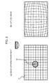
- Fig. 2 is a diagram illustrating an example of an image captured using a wide-angle lens.
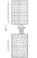
- Fig. 3 is a diagram illustrating overhead conversion which is an example of correction of an image captured using a wide-angle lens.
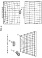
- Fig. 4 is a diagram illustrating overhead conversion which is an example of correction of an image captured using a wide-angle lens.
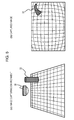
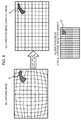
- Fig. 5 is a diagram illustrating an example of an image captured using a wide-angle lens in a case where the image includes a stereoscopic object as a subject.
- Fig. 1 is a diagram illustrating an example in which cameras are mounted on a vehicle.
- Fig. 2 is a diagram illustrating an example of an image captured using a wide-angle lens.
- Fig. 3 is a diagram illustrating overhead conversion which is an example of correction of an image captured using a wide-angle lens.
- Fig. 4 is a diagram illustrating overhead conversion which
- FIG. 6 is an example of correction of an image captured using a wide-angle lens, and is a diagram illustrating overhead conversion in a case where the image includes a stereoscopic object as a subject.
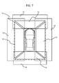
- Fig. 7 is a diagram illustrating an example of a process of synthesizing a plurality of overhead images.
- Fig. 8 is a diagram illustrating an example of a synthesis image.
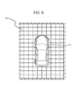
- Fig. 9 is a diagram illustrating an example in which a stereoscopic object disappears from a synthesis image based on overhead images.
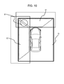
- Fig. 10 is a diagram illustrating an example in which a stereoscopic object disappears from a synthesis image based on overhead images.
- Fig. 10 is a diagram illustrating an example in which a stereoscopic object disappears from a synthesis image based on overhead images.
- FIG. 11 shows a synthesis image generated according to an embodiment of the present disclosure, and is a diagram illustrating an example of a synthesis image which is displayed on a display unit provided at a driver's seat of a vehicle.
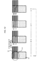
- Fig. 12 is a diagram illustrating an example in which a display mode changes with a change in time in a junction region of a synthesis image according to an embodiment of the present disclosure.
- Fig. 13 is a diagram illustrating an embodiment in which a stereoscopic object is displayed in a junction region of a synthesis image according to an example of the present disclosure.
- Fig. 14 is a diagram illustrating parameters applied to a display control of a synthesis image according to an embodiment of the present disclosure.
- Fig. 12 is a diagram illustrating an example of a synthesis image which is displayed on a display unit provided at a driver's seat of a vehicle.
- Fig. 12 is a diagram illustrating an example in which a display mode changes with a change in time in a junction region
- Fig. 15 is a diagram illustrating parameters applied to a display control of a synthesis image according to an embodiment of the present disclosure.
- Fig. 16 is a diagram illustrating parameters applied to a display control of a synthesis image according to an embodiment of the present disclosure.
- Fig. 17 is a flow chart illustrating a display control sequence of a synthesis image according to an embodiment of the present disclosure.
- Fig. 18 is a diagram illustrating an example in which a stereoscopic object is displayed in a junction region of a synthesis image according to an embodiment of the present disclosure.
- Fig. 19 shows a synthesis image generated according to an embodiment of the present disclosure, and is a diagram illustrating an example of a synthesis image which is displayed on a display unit provided at a driver's seat of a vehicle.
- Fig. 20 is a diagram illustrating an embodiment in which a display mode changes with a change in time in a junction region of a synthesis image according to an example of the present disclosure.
- Fig. 21 is a diagram illustrating an embodiment in which a stereoscopic object is displayed in a junction region of a synthesis image according to an example of the present disclosure.
- Fig. 22 is a diagram illustrating an embodiment in which a stereoscopic object is displayed in a junction region of a synthesis image according to an example of the present disclosure.
- Fig. 23 shows a synthesis image generated according to an embodiment of the present disclosure, and is a diagram illustrating an example of a synthesis image displayed on a display unit provided at a driver's seat of a vehicle.
- Fig. 21 is a diagram illustrating an embodiment in which a stereoscopic object is displayed in a junction region of a synthesis image according to an example of the present disclosure.
- Fig. 22 is a diagram illustrating an embodiment in which a
- Fig. 24 is a diagram illustrating an example in which a display mode changes with a change in time in a junction region of a synthesis image according to an embodiment of the present disclosure.
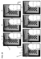
- Fig. 25 is a diagram illustrating an example in which a stereoscopic object is displayed in a junction region of a synthesis image according to an embodiment of the present disclosure.
- Fig. 26 is a diagram illustrating an example in which a stereoscopic object is displayed in a junction region of a synthesis image according to an embodiment of the present disclosure.
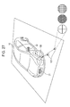
- Fig. 27 is a diagram illustrating laser irradiation patterns which are auxiliary information used when generating a synthesis image.
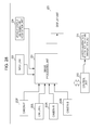
- Fig. 28 is a diagram illustrating an example of a hardware configuration of an image processing apparatus of the present disclosure.
- Fig. 29 is a diagram illustrating an example of a hardware configuration of an image processing apparatus of the present disclosure.
- Fig. 1 is a diagram illustrating an example in which cameras are mounted on a vehicle.
- a camera F21, a camera L22, a camera R23, and a camera B24 are mounted on the front, left, right, and back of the vehicle 10, respectively.
- each of the cameras F21 to R24 is configured to include a wide-angle lens such as, for example, a fish-eye lens and to capture images of the ground and a stereoscopic object on the ground over a wide range by setting an imaging direction to a downward direction (ground direction).
- a wide-angle lens such as, for example, a fish-eye lens
- Fig. 2(a) shows an image capturing environment.
- a subject 31 is the ground on which a grid pattern is drawn.
- a wide-angle camera 30 is set on the top center of the subject 31 to perform image capturing.
- the camera 30 is a camera having a wide-angle lens such as, for example, a fish-eye lens mounted thereon.
- An example of an image captured in the image capturing environment shown in Fig. 2(a) is a captured image shown in Fig. 2(b).
- the grid pattern of the ground on the captured image has curved distortion.
- the distortion is distortion of an image which occurs due to image capturing using a wide-angle lens.
- Fig. 3 shows a captured image which is the same as that in Fig. 2(b) and a corrected image (overhead image) generated by a correction process (overhead conversion) of the captured image, respectively.
- an image observed from above is referred to as an "overhead image”, and an image correction process of performing conversion to an “overhead image” is referred to as “overhead conversion”.
- the corrected image shown in Fig. 3(c) is an "overhead image”, and a correction process of generating the corrected image from the captured image of Fig. 3(b) is equivalent to "overhead conversion”.
- the corrected image (overhead image) of Fig. 3(c) is an image having the same grid pattern as that of the subject 31 in the above-described image capturing environment of Fig. 2(a) and is a correct overhead image viewed from above the ground, and the grid pattern of the ground is a pattern in which the shape of a real subject is restored.
- Fig. 4 is a diagram illustrating an example of a process of correcting an image captured by a wide-angle camera, such as a fish-eye camera, which is mounted toward an obliquely downward direction.
- a wide-angle camera such as a fish-eye camera
- FIG. 4(a) an image of the ground on which a grid pattern is drawn is captured as the subject 31 by the wide-angle camera 30 mounted toward the obliquely downward direction.
- Figs. 4(b) and 4(c) show a captured image captured in an image capturing environment shown in Fig. 4(a) and a corrected image, respectively.
- a so-called distortion-corrected image which is converted to a center captured image by removing fish-eye distortion of the image shown in Fig. 4(b), is the corrected image shown in Fig. 4(c).
- a trapezoid of the subject 31 (ground on which a tetragonal grid pattern is drawn) is obtained from a series of images, shown in Fig. 4(b), captured from an oblique position of the wide-angle camera 30, reflecting a perspective by performing a fish-eye distortion correction process.
- a trapezoid image shown in Fig. 4(c) is obtained in which curved distortion of the captured image is removed and a perspective remains.
- the above-described integrated conversion process in which the distortion conversion of the image viewed from the oblique direction is combined with the overhead conversion will be collectively referred to as "overhead conversion".
- the overhead conversion serves as a process including a process of converting an image viewed obliquely from above to an image viewed from above.
- a description of the process in which the image is viewed from the oblique direction will be omitted below.
- Fig. 3 shows the example of a conversion process performed using the ground on which a grid pattern is drawn, as a reference plane, and the grid pattern drawn on the ground is restored with a high level of accuracy.
- Fig. 5 shows an image capturing environment and a captured image, respectively.
- the image capturing environment of Fig. 2(a) includes the ground on which a grid pattern is drawn.
- a stereoscopic object 32 extending upwards from the ground is set.
- the wide-angle camera 30 is installed at a finite distance on the ground, and is set toward the ground. Similarly to the above description given with reference to Fig. 2(b), in the captured image of Fig. 2(b), distortion occurs in the grid pattern of the ground. Further, an image of the stereoscopic object 32 is also captured in a distorted state.
- Fig. 6 is a diagram showing an example of a process of correcting a captured image of Fig. 6(b), that is, an overhead conversion process in which a ground plane is used as a reference plane.
- FIG. 6(d) A reference image shown in Fig. 6(d) is an example of an overhead image which is ideally observed from infinity. In this image, the stereoscopic object 32 is observed from directly above. Meanwhile, Fig. 6 is a schematic diagram, and distortion remaining in the stereoscopic object 32 by overhead conversion changes in various ways depending on the position and height thereof.
- Figs. 7 and 8 describe a process of generating a synthesis image by connecting images captured by a plurality of wide-angle cameras mounted on a vehicle.
- Fig. 7 is a diagram illustrating an example of image regions captured by four cameras mounted on four faces of front, rear, right, and left faces of the vehicle which are described above with reference to Fig. 1, and synthesis regions applied to generate a synthesis image.
- a front image capturing region 51 shown in Fig. 7 shows a region captured by the camera F21 shown in Fig. 1.
- a left side image capturing region 52 shows a region captured by the camera L22
- a right side image capturing region 53 shows a region captured by the camera R23
- a rear image capturing region 54 shows a region captured by the camera B24.
- overhead images are generated by performing overhead conversion on these four captured images, and then the overhead images are joined to each other to form one synthesis image.
- dotted-line trapezoid regions shown in Fig. 7 are regions (synthesis region) which are selected as components of a synthesis image 70 from the respective captured images.
- the synthesis image 70 is generated by connecting the following four synthesis regions.
- a front image synthesis region 61 which is a portion of the front image capturing region 51
- a left side image synthesis region 62 which is a portion of the left side image capturing region 52
- a right side image synthesis region 63 which is a portion of the right side image capturing region 53
- a rear image synthesis region 64 which is a portion of the rear image capturing region 54
- overhead conversion is performed on the images before the synthesis process. That is, four overhead images generated by performing the overhead conversion process are synthesized.
- One synthesis image 70 is generated by the synthesis process.
- Fig. 8 shows an example of the synthesis image 70.
- the synthesis image 70 is equivalent to an image in which the ground in the vicinity of a vehicle is observed from above centering on a vehicle image 71.
- the vehicle image 71 is not an image captured by a camera, but is a pseudo image of a vehicle mounted on this system which is provided in advance.
- a data processing unit generating an image to be output to a display unit provided at a driver's seat of the vehicle executes a process of attaching the vehicle image 71 to an image (overhead image) of the vehicle surroundings which is generated by performing overhead conversion and a synthesis process on an image captured by a camera to generate the images to be output and displays the image on the display unit.
- a driver observes the image to ascertain a situation of the surroundings of the vehicle and to drive safely.
- a synthesis image in which a plurality of overhead images are connected to each other is generated, there is a problem in that subjects standing on the ground on a boundary between adjacent cameras are joined to each other and thus disappear from the overhead images.
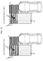
- Fig. 9 is a diagram showing an example of a process of synthesizing the front image synthesis region 61 and the left side image synthesis region 62.
- Fig. 9(a) shows the position of the stereoscopic object 32 on an image obtained by performing overhead conversion on an image captured in the left side image capturing region 52 and the left side image synthesis region 62.
- the overhead conversion image is equivalent to, for example, the corrected image (overhead image) which is described above with reference to Fig. 6(c).
- the stereoscopic object 32 is converted and projected onto a position shifted from the left side image synthesis region 62 having a trapezoid shape.
- Fig. 9(b) shows the position of the stereoscopic object 32 on an image obtained by performing overhead conversion on an image captured in the front image capturing region 51 and the front image synthesis region 61.
- the stereoscopic object 32 is also converted and projected onto a position shifted from the front image synthesis region 61 having a trapezoid shape.
- the left side image synthesis region 62 having a trapezoid shape and the front image synthesis region 61 having a trapezoid shape are joined to each other, and thus a final synthesis image is generated.
- the resulting synthesis image does not include an image of the stereoscopic object 32 and disappears. That is, as shown in Fig. 10, the stereoscopic object 32 is not included in a junction region 81 between a left side image and a front image of the synthesis image 70, and the synthesis image 70 in which the stereoscopic object 32 disappears is generated.
- a stereoscopic object is not displayed in the synthesis image displayed on the display unit at the driver's seat.
- the driver is not able to recognize an obstacle, which results in a possibility of the driver driving dangerously.
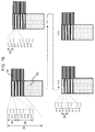
- a process is performed of dynamically changing display regions of images to be synthesized in a junction region between the images. This embodiment will be described below with reference to Fig. 11 and the subsequent drawings.
- Fig. 11 is a diagram showing a portion of a synthesis image displayed on a display unit provided at a driver's seat of a vehicle.
- Fig. 11 shows the vicinity of a junction region 103 between a front image 101 and a left side image 102 which are images constituting the synthesis image.
- both the front image 101 and the left side image 102 shown in Fig. 11 are images after an overhead conversion process is performed thereon.
- the front image 101 is an image obtained by performing overhead conversion on an image captured by a front camera (equivalent to the camera F shown in Fig. 1) which is mounted on the front of the vehicle.
- the left side image 102 is an image obtained by performing overhead conversion on an image captured by a left side camera (equivalent to the camera L shown in Fig. 1) which is mounted on the left side of the vehicle.
- the junction region 103 between the front image 101 and the left side image 102 has the following configuration.
- Display regions of the front image 101 and the left side image 102 are alternately set in units of rectangular strip regions, and the strip positions are sequentially moved with a change in time.
- a process of changing the display regions of the front image 101 and the left side image 102 within the junction region 103 with a change in time that is, a dynamic changing process of the display regions is executed.
- Fig. 12 is a diagram showing an example of a process of changing the junction region 103 between the front image 101 and the left side image 102 with a change in time.
- Time changes in the order of t1, t2, t3, and t4, and states of changes in the display mode of the junction region at the respective times are shown.
- the strip region of the front image 101 is sequentially moved upwards with a change in time (t1->t2->t3->t4).
- the time t4 and the subsequent times have the same strip position as that of the time t1. Further, t6, t7, and t8 are set in the same manner as t2, t3, and t4, respectively, and then the same movement of the strip is repeated.
- junction region 103 between the front image 101 and the left side image 102 is a rectangular region. In the rectangular region, some portions correspond to the display region of the front image 101, and the other portions correspond to the display region of the left side image 102.
- the display regions are sequentially changed with a change in time.
- the display period of the front image 101 and the display period of the left side image 102 are alternately set in all the rectangular regions constituting the junction region 103.
- the entire region of the junction region 103 corresponds to a region in which two of the front image 101 and the left side image 102 can be confirmed.
- the displays of the display regions of the respective overhead images are dynamically changed, that is, the displays of the display regions of the respective overhead images are sequentially changed with a change in time, thereby solving the problem, described above with reference to Figs. 9 and 10, that the stereoscopic object disappears from the synthesis image.
- a boundary line of a stereoscopic object dynamically runs on a screen by sequentially and variably moving the boundaries of the images in time series.
- the entire region of the junction region 103 is set to a region in which two of the front image 101 and the left side image 102 can be confirmed, the display region of the stereoscopic object is not completely cut off, and the dynamic boundary line moves, thereby allowing a certain stereoscopic object to be recognized.
- junction region a stereoscopic object looks like it is moving along a boundary as compared with the other region (static region) in the synthesis image, and thus the junction region functions as an attention-drawing region.
- Such an attention-drawing region serves as effective means for detecting a stereoscopic object which is present in the junction region for an observer (driver).
- a configuration is preferably given in which a strip width of the front image 101 and a strip width of the left side image 102, which are set in the junction region 103, are not equal to each other and any one of the strip widths is set to be larger than the other.
- an observer can preferentially and visually confirm any one image of the front image 101 and the left side image 102 within the junction region 103, that is, an image which is set to have a larger strip width, which makes it easier to more exactly confirm situations in association with the dynamic movement of the boundary of the stereoscopic object.
- Fig. 13 shows an example in which a stereoscopic object is displayed in two display modes at the time t1 and the time t3 among the display modes, described above with reference to Fig. 12, of the junction region at the time t1 to the time t4. That is, examples are shown in which the following two synthesis images are displayed.
- a display region of a stereoscopic object is included in each of a front image region and a left side image region which have a strip shape and are set to a junction region.
- a stereoscopic object 111 within the front image is displayed in the front image display region of the junction region in which a strip is set.
- a stereoscopic object 112 within the left side image is displayed in the left side image display region of the junction region in which a strip is set.
- the stereoscopic object is equivalent to a subject (stereoscopic object) which is cut off in the above-described synthesis image of Fig. 9 and disappears from the synthesis image.
- this process example is configured such that all of two overhead images to be joined can be observed in a junction region between the overhead images without cutting off ends of the overhead images, and thus it is possible to observe all subjects included in the overhead images.
- Fig. 13 shows display modes of synthesis images at two different timings, respectively.
- a display region of a front image is different from a display region of a left side image with a change in time, and display regions of a stereoscopic object within the respective images are different from each other with a change in time.
- the observer's (driver's) attention has a tendency to face an image region where display information changes, rather than a static region having no change.
- the observer's (driver's) eyes have a tendency to face a junction region where display information dynamically changes, and thus it is possible to increase the probability of a stereoscopic object displayed in the junction region being confirmed without being overlooked.
- a process sequence to be described below is a sequence of a display control process of setting an image junction region in which two overhead images are alternately disposed in a strip shape, and executing a display control for sequentially moving strip regions of the images disposed in the image junction region with the lapse of the time.
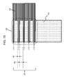
- Figs. 15 and 16 are diagrams illustrating a configuration example of the junction region 103 between the front image 101 and the left side image 102 and the setting of the parameters.
- Both the front image 101 and the left side image 102 which are shown in Figs. 15 and 16 are overhead images after overhead conversion as a correction process is performed thereon.
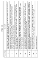
- parameters to be used in the display control process of the junction region 103 are as follows.
- ZN strip number specification value, maximum value of strip identifier (i) capable of being set in junction region of image (in this example, front [f] image) in which strip identifier i is set
- Wf strip width specification value, maximum value of line identifier (j) which is equivalent to width of one strip of image (in this example, front [f] image) in which strip identifier i is set
- Ws strip width specification value, the number of lines equivalent to strip width of the other image (in this example, left side [s] image) which is image (in this example, a front [f] image) in which strip identifier i is not set
- Wf+Ws alternate display strip interval specification value in junction region, the number of lines equivalent to strip interval of image (in this example, front [f] image) in which strip identifier i is set
- SW strip shift width specification value, the number of strip shift lines per unit frame of image (in this example, front [f] image) in which strip identifier i is set
- the display control of the junction region 103 is executed using these parameters.
- the strip identifier i is a strip identifier of any one image (in this example, the front [f] image) of the junction region.
- identifiers i, i+1, and i+2 are set in order from the top.
- the strip identifier i is set as 0, 1, 2, 3..., using 0 as a first strip identifier.
- the line identifier j is an identifier indicating the number of lines from each strip starting position of any one image (in this example, a front [f] image) of a junction region.
- a configuration is preferably given in which a strip width of the front image 101 and a strip width of the left side image 102, which are set in the junction region 103, are not equal to each other and in which any one of the strip widths, which is more effective by being shown to a driver more, is set to be larger than the other.
- an observer can preferentially confirm the left side image 102 which is set to have a larger strip width within the junction region 103, and thus confirms a stereoscopic object more easily.
- the strip number specification value ZN is the maximum value of the strip identifier (i) which can be set in a junction region of an image (in this example, the front [f] image) in which the strip identifier i is set.
- the strip with specification value Wf is the maximum value of the line identifier (j) which is equivalent to a width of one strip of an image (in this example, a front [f] image) in which the strip identifier i is set.
- the strip width specification value Ws is a strip width specification value, and is the number of lines equivalent to a strip width of the other image (in this example, a left side [s] image) which is an image (in this example, a front [f] image) in which the strip identifier i is not set.
- the alternate display strip interval specification value Wf+Ws is an alternate display strip interval specification value in a junction region, and is the number of lines equivalent to a strip interval of an image (in this example, a front [f] image) in which the strip identifier i is set.
- the strip shift width specification value SW is the number of strip shift lines per unit frame of an image (in this example, a front [f] image) in which the strip identifier i is set.
- the display frame identifier f is an identifier indicating a display frame number.
- a shift process of a strip of a junction region is sequentially executed in units of one frame in the order of a frame f, a frame f+1, a frame f+2, and a frame f+3.
- the strip is moved in any one direction of an upward direction and a downward direction.
- the shift process is executed in units of one frame in this example, but is not limited thereto.
- the process may be set to be executed in units of ten frames.
- the moving speed of the strip is set to be lower.
- the display control of the junction region 103 is executed using these parameters.
- a processing flow shown in Fig. 17 is a flow illustrating a display control process sequence of a partial region of a synthesis image generated from a plurality of overhead images.
- the display control process sequence is equivalent to a control sequence of a display process of the junction region 103 shown in Fig. 15 and the image region of the left side image 102 below the junction region.
- a data processing unit that executes a display control of a display unit mounted on a vehicle.
- the data processing unit includes a CPU having a function of executing a program, and controls a process based on a program in which the process sequence according to the flow shown in Fig. 16 is recorded.
- the program is stored in a memory, a storage medium, or the like, which is a storage unit accessible by the data processing unit (control unit).
- a configuration may be given in which the program is acquired from an external server or the like through a communication unit.
- step S101 and the subsequent processes are executed.
- step S101 a j-th line of a front image is output as a line constituting a junction region of a synthesis image.
- step S101 is equivalent to a process of generating a strip region constituted by the front image 101 shown in Figs. 15 and 16.
- a 0-th line of the front image is output.
- step S102 a process of comparing the line identifier j with the strip width specification value Wf is executed.
- the strip width specification value Wf is the maximum value of the line identifier (j) which is equivalent to the width of one strip of an image (in this example, a front [f] image) in which the strip identifier i is set.
- step S102 it is determined whether the line identifier j is equal to or greater than the strip width specification value Wf. That is, it is determined whether a determination expression of "j is equal to or greater than Wf" is established.
- This determination expression is a process for determining whether the number of lines of the front image which is output in step S101, that is, the number of lines constituting the strip of the front image 101 reaches the strip width specification value Wf.
- step S102 determines whether the process is Yes, and thus the process proceeds to step S104.
- step S101 After the parameter is updated in step S103, a process corresponding to the updated line identifier j is executed in step S101.
- the first line of the front image is output as a line constituting the junction region of the synthesis image.
- step S101 A loop from step S101 to step S103 is repeated until the determination expression of step S102, that is, a determination expression of "j is equal to or greater than Wf" is established. That is, the line constituting the front image 101 is output to the junction region 103 until the line identifier j reaches the strip width specification value Wf.
- step S105 the j-th line of the left side image is output as a line constituting the junction region of the synthesis image.
- step S105 is executed.
- step S106 a process is performed of comparing the line identifier: j with a value obtained by adding the strip width specification value Wf of the front [f] image and the strip width specification value Ws of the left side [s] image (Wf+Ws: alternate display strip interval specification value).
- the strip width specification value Wf is the maximum value of the line identifier (j) which is equivalent to the width of one strip of an image (in this example, the front [f] image) in which the strip identifier i is set.
- the strip width specification value Ws is the number of lines equivalent to a strip width of the other image (in this example, the left side [s] image) which is an image (in this example, the front [f] image) in which the strip identifier i is not set.
- step S106 it is determined whether the line identifier j is equal to or greater than the value obtained by adding the strip width specification value Wf and the strip width specification value Ws (Wf+Ws: alternate display strip interval specification value). That is, it is determined whether a determination expression of "j is equal to or greater than (Wf+Ws)" is established.
- This determination expression is a process for determining whether the sum of the number of lines constituting the strips which have been already generated by a non-repetitive process of step S101 and the number of lines constituting the strips being generated in step S105 reaches the sum of the strip interval specification values Wf and the strip width specification values Ws of two images in the junction region (Wf+Ws: alternate display strip interval specification value).
- step S106 determines whether the process returns to step S104.
- step S105 is repeatedly executed.
- step S106 A loop from step S104 to step S106 is repeated until the determination expression of step S106, that is, a determination expression of "j is equal to or greater than (Wf+Ws)" is established. That is, for example, as shown in Fig. 16, the line constituting the left side image 102 is output to the junction region 103 until the line identifier j reaches the sum of the strip width specification value Wf and the strip width specification value Ws (Wf+Ws: alternate display strip interval specification value).
- step S104 to S106 When the repetitive loop of step S104 to S106 is terminated, one region between the strips of the junction region is completed.
- step S107 a process of comparing the strip identifier i with the strip number specification value ZN is executed.
- the strip identifier i is a strip identifier of any one image (in this example, the front [f] image) of the junction region.
- the identifiers i, i+1, and i+2 are set in order from the top.
- the strip identifier i is set as 0, 1, 2, 3..., using 0 as a first strip identifier.
- the strip number specification value ZN is the maximum value of the strip identifier (i) which can be set in a junction region of an image (in this example, the front [f] image) in which the strip identifier i is set.
- step S107 it is determined whether the strip identifier i is set to be equal to or greater than the strip number specification value ZN. That is, it is determined whether a determination expression of "i is equal to or greater than ZN" is established.
- step S107 determines whether the strip identifier i by one and resetting the line identifier j to 0. Then, the processes of step S101 to step S106 are repeated.
- one strip region is generated by outputting three lines of the front image 101, and a region between the strips is generated by outputting five lines of the left side image 102.
- This process is repeated a specified number of times, that is, until the determination expression of "i is equal to or greater than ZN" in step S107 is satisfied.
- This process is repeated, thereby completing, for example, a configuration in which the image within the junction region 103 shown in Fig. 15 is output. That is, an image is completed of the junction region which is constituted by a repetitive configuration including three lines of strip images of the front image 101 and five lines of images between the strips of the left side image.
- step S109 a process is executed of sequentially attaching the lines of the left side image to a continuous region of the junction region of the synthesis image.
- this process is equivalent to the process of outputting the left side image 102 below the junction region 103 shown in Fig. 15.
- step S110 it is determined whether the output of the image for one frame is terminated.
- step S109 When the output is not terminated, the process returns to step S109 to sequentially output the lines constituting the left side image 102.
- step S110 When it is determined in step S110 that the output of the image for one frame is terminated, the process proceeds to step S111.
- the flow shown in Fig. 17 is a flow in which a display control is executed of a portion of the synthesis image, that is, regions to be output of the junction region 103 shown in Fig. 15 and the left side image 102 below the junction region.
- this process is equivalent to a process of performing transition from the frame f to the frame f+1 shown in Fig. 16.
- step S112 a process is performed of shifting a j-th line in which a display is started, by a predetermined number of lines (SW).
- SW is a strip shift width specification value, and is the number of strip shift lines per unit frame of an image (in this example, the front [f] image) in which the strip identifier i is set.
- step S101 and the subsequent processes are executed.
- the strips in the junction region are sequentially shifted, and the display regions of the front image 101 and the left side image are changed and displayed with a change in time.
- the amount of shift (SW) per one frame can be variously set, and it is possible to change a moving speed of the strip in various ways in accordance with the setting of the amount of shift (SW).
- the shift process is executed in units of one frame in this example, but is not limited thereto.
- the process may be executed in units of any number of frames or in units of n frames.
- n is an integer equal to or greater than 1.
- n may be increased, and n may be set to 10 or 20. With such a configuration, the moving speed of the strip is set to be lower.
- the above-described embodiment is configured to change display regions of two overhead conversion images with a change in time in a junction region between the overhead conversion images.
- Fig. 18 shows a display example in which a stereoscopic object displayed in the junction region 103 between the front image 101 and the left side image 102.
- the stereoscopic object is displayed as a stereoscopic object 111 within the front image in the strip region which is the display region of the front image 101, and is displayed as a stereoscopic object 112 within the left side image in the region between strips which is the display region of the left side image.
- the display of the stereoscopic objects is highlighted. Specifically, highlighting is performed in a conspicuous display mode by a blinking display or by changing color, brightness, and the like.
- the degree of highlighting in the junction region is set in any one of the following manners.
- a difference between pixel values of the front image 101 and the left side image 102 is calculated, and the region having a larger difference between the pixel values is determined to be a display region of the stereoscopic object.
- overhead conversion is a conversion process performed on the basis of one reference plane.
- the reference plane is the ground. Since distortion of the front image 101 and the left side image 102 is removed with respect to the ground, subjects located on the same ground are displayed on the positions of the corresponding pixels of the respective images. Accordingly, pixel values of the positions of the corresponding pixels of the respective images are substantially the same, and a difference therebetween hardly occurs.
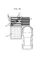
- Fig. 19 is a diagram showing a portion of a synthesis image which is displayed on a display unit provided at a driver's seat of a vehicle. That is, Fig. 19 is a diagram showing the vicinity of a junction region 103 between a front image 101 and a left side image 102 which are images constituting the synthesis image.
- both the front image 101 and the left side image 102 shown in Fig. 19 are images after an overhead conversion process is performed thereon.
- the front image 101 is an image obtained by performing overhead conversion on an image captured by a front camera (equivalent to the camera F shown in Fig. 1) which is mounted on the front of a vehicle.
- the left side image 102 is an image obtained by performing overhead conversion on an image captured by a left side camera (equivalent to the camera L shown in Fig. 1) which is mounted on the left side of the vehicle.
- This embodiment is configured such that display regions of the front image 101 and the left side image 102 are alternately set in units of curved strip type display regions in the junction region 103 between the front image 101 and the left side image 102. Further, thess strip positions are sequentially moved with a change in time.
- the display regions of the front image 101 and the left side image 102 in the junction region 103 are set to change with a change in time.
- Fig. 20 is a diagram showing a change in the junction region 103 between the front image 101 and the left side image 102 with a change in time. Time changes in the order of t1, t2, and t3, and states of changes in the junction region at the respective times are shown.
- the strip region having a curved shape of the front image 101 is sequentially moved obliquely in an upper left direction with a change in time (t1->t2->t3). Meanwhile, at the time t4, the time t3 and the subsequent times have the same strip position as that of the time t1. Further, t5 and t6 are set in the same manner as t2 and t3, respectively, and then the same movement of the strip is repeated.
- the display regions of the front image 101 and the left side image 102 are alternately set in units of curved strips within the junction region 103. However, the display regions are sequentially changed with a change in time.
- the display period of the front image 101 and the display period of the left side image 102 are alternately set in the entirety of the junction region 103, and an observer can confirm two of the front image 101 and the left side image 102 in the entirety of the junction region 103.
- the entirety of the junction region 103 is set to a region where two of the front image 101 and the left side image 102 can be confirmed, the display region of the stereoscopic object can be confirmed without being cut off.
- the junction region serves as a display region changing with a change in time, and thus serves as a region drawing an observer's attention. That is, the junction region serves as a region which further draws attention, that is, an attention-drawing region as compared with the other regions (static regions) in the synthesis image.
- the observer driver
- an observer can preferentially and visually confirm any one image of the front image 101 and the left side image 102 within the junction region 103, that is, an image which is set to have a larger strip width, which makes it easier to confirm the stereoscopic object.
- Fig. 21 is a diagram showing an example in which the synthesis image according to this embodiment is actually displayed.
- Fig. 21 shows changes in display information of a junction region with a change in time. The position of a fan-shaped strip is gradually moved. A stereoscopic object can be observed in the junction region.
- a stereoscopic object 151 within a front image which is shown in the drawing is a stereoscopic object displayed in a front image display region.
- a stereoscopic object 152 within a left side image is a stereoscopic object displayed in a left side image display region.
- the stereoscopic objects are subjects (stereoscopic objects) included in the image region which is cut off in the above-described process of Fig. 9.
- This process example is configured such that all of two overhead images to be joined can be observed in a junction region between the overhead images without cutting off ends of the overhead images, and thus it is possible to observe all subjects included in the overhead images.
- Fig. 22 shows a display example in which a stereoscopic object displayed in the junction region 103 between the front image 101 and the left side image 102.
- the stereoscopic object is displayed as the stereoscopic object 151 within the front image in the strip region which is the display region of the front image 101, and is displayed as the stereoscopic object 152 within the left side image in the region between strips which is the display region of the left side image.
- the display of the stereoscopic objects is highlighted. Specifically, highlighting is performed in a conspicuous display mode by a blinking display or by changing color, brightness, and the like.
- SAD sum of absolute differences
- Fig. 23 is a diagram showing a portion of a synthesis image which is displayed on a display unit provided at a driver's seat of a vehicle. That is, Fig. 23 is a diagram showing the vicinity of a junction region 103 between a front image 101 and a left side image 102 which are images constituting the synthesis image.
- both the front image 101 and the left side image 102 shown in Fig. 23 are images after an overhead conversion process is performed thereon.
- the front image 101 is an image obtained by performing overhead conversion on an image captured by a front camera (equivalent to the camera F shown in Fig. 1) which is mounted on the front of a vehicle.
- the left side image 102 is an image obtained by performing overhead conversion on an image captured by a left side camera (equivalent to the camera L shown in Fig. 1) which is mounted on the left side of the vehicle.
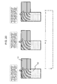
- This embodiment is configured such that display regions of the front image 101 and the left side image 102 are partitioned by one image boundary 161 in the junction region 103 between the front image 101 and the left side image 102.
- the image boundary 161 is moved with a change in time.
- Fig. 24 is a diagram showing the movement of the image boundary 161 between the front image 101 and the left side image 102, which is set within the junction region 103 between the front image 101 and the left side image 102, with a change in time. Time changes in the order of t1, t2, and t3, and states of changes in the position of the image boundary 161 within the junction region at the respective times are shown.
- the image boundary 161 is rotated clockwise centering on the lower left end of the junction region 103.
- the entirety of the junction region 103 is set to the display region of the front image 101. Thereafter, the image boundary 161 is rotated clockwise from the time t1 to the time t4, and the display region of the front image 101 in the junction region 103 is sequentially switched to the display region of the left side image 102 from the lower left side thereof.
- the entirety of the junction region 103 is set to the display region of the left side image 102. Thereafter, the image boundary 161 is rotated counterclockwise from the time t4 to the time t7, and the display region of the left side image 102 in the junction region 103 is sequentially switched to the display region of the front image 101 from the upper right side thereof.
- the entirety of the junction region 103 is set to the display region of the front image 101 at the time t7.
- the image boundary 161 repeats the same movement, that is, the right rotation and left rotation thereof. That is, the image boundary reciprocates in the same manner as a windshield wiper of a vehicle.
- the synthesis image of this embodiment has a junction region which is set such that a boundary position repeats the right rotation and left rotation thereof centering on a predetermined point.
- a configuration is preferably given in which the speed of the right rotation is not the same as the speed of the left rotation and the rotation speed in any one direction is set to be lower than the rotation speed in the other direction.
- the rotation speeds are set to be different from each other, for example, at a ratio of 1 to 2 or more.
- an observer can preferentially observe an image in a case of slow rotation, and thus easily confirm the entire image of a stereoscopic object at that time.
- display periods of the front image 101 and the left side image 102 are set in the entirety of the junction region 103, and the observer can confirm two of the front image 101 and the left side image 102 in the entirety of the junction region 103.
- the entirety of the junction region 103 is set to a region where two of the front image 101 and the left side image 102 can be confirmed, the display region of the stereoscopic object can be confirmed without being cut off.
- Fig. 25 is a diagram showing an example in which the synthesis image according to this embodiment is actually displayed.
- Fig. 25 shows changes in display information of a junction region with a change in time.
- the image boundary 161 is gradually moved. A stereoscopic object can be observed in the junction region.
- a stereoscopic object 172 within a left side image which is shown in the drawing is a stereoscopic object displayed in a left side image display region.
- a stereoscopic object 171 within a front image is a stereoscopic object displayed in a front image display region.
- the stereoscopic objects are subjects (stereoscopic objects) included in the image region which is cut off in the above-described process of Fig. 9.
- This process example is configured such that all of two overhead images to be joined can be observed in a junction region between the overhead images without cutting off ends of the overhead images, and thus it is possible to observe all subjects included in the overhead images.
- the junction region serves as a display region changing with a change in time, and thus serves as a region drawing an observer's attention. That is, the junction region serves as a region which further draws attention, that is, an attention-drawing region as compared with the other regions (static regions) in the synthesis image.
- the observer driver
- Fig. 26 shows a display example in which a stereoscopic object displayed in the junction region 103 between the front image 101 and the left side image 102.
- the stereoscopic object is displayed as the stereoscopic object 171 within a front image in the display region of the front image 101, and is displayed as the stereoscopic object 172 within a left side image in the region between strips which is the display region of the left side image.
- the display of the stereoscopic objects is highlighted. Specifically, highlighting is performed in a conspicuous display mode by a blinking display or by changing color, brightness, and the like.
- SAD sum of absolute differences
- All the above-described embodiments desire a process of generating one synthesis image by synthesizing images captured by a plurality of cameras mounted at different positions.
- positions where the plurality of cameras capturing images are capable of performing image capturing are irradiated with a specific pattern, and then the cameras perform image capturing. It is possible to generate a synthesis image having a small positional deviation by executing positioning using the irradiation patterns included in the images captured by the respective cameras.
- a laser calibration reference pattern irradiation unit 180 shown in Fig. 27 irradiates the ground with a calibration reference pattern 181 having a certain image pattern as shown in the drawing.
- the irradiation with the calibration reference pattern 181 is performed on a position where the camera F21 on the front of the vehicle 10 and the camera L22 on the left side of the vehicle 10 are capable of image capturing.
- the calibration reference pattern 181 has a specific pattern such as, for example, a cross and a grid-shaped pattern.
- the laser calibration reference pattern irradiation unit 180 is constituted by, for example, a solid laser light source and a pattern generating holographic filter.
- the calibration reference pattern 181 is captured in the images captured by the camera F21 on the front of the vehicle 10 and the camera L22 on the left side of the vehicle 10.
- the laser calibration reference pattern irradiation unit 180 shown in Fig. 27 may be configured to execute irradiation with a calibration reference pattern in accordance with image capturing timings of image capturing frames at which the cameras capture images, rather than to continuously execute laser irradiation.
- the plurality of cameras perform image capturing in association with an irradiation timing of the calibration reference pattern.
- An image processing unit detects the calibration reference pattern from differences between a plurality of continuous captured image frames, and executes an image synthesis process in which regions irradiated with the calibration reference pattern are applied to image positioning at the time of generating a synthesis image.
- an image processing apparatus may be configured to execute calibration, as a camera adjustment process to which a captured image including a calibration reference pattern is applied, at fixed intervals or at the time of generating a synthesis image.
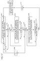
- Fig. 28 is a diagram showing a configuration example of the entirety of an image processing apparatus including an image processing unit 201 that executes the image display process according to the above-described embodiments and a plurality of cameras that capture images to be processed.
- a camera F 202F is equivalent to the camera F21, shown in Fig. 1, which is provided on the front of the vehicle 10.
- a camera L 202L is equivalent to the camera L22, shown in Fig. 1, which is provided on the left side of the vehicle 10.
- a camera R 202R is equivalent to the camera R23, shown in Fig. 1, which is provided on the right side of the vehicle 10.
- a camera B 202B is equivalent to the camera B24, shown in Fig. 1, which is provided on the back of the vehicle 10.
- Each of the cameras which is a camera including a wide-angle lens such as, for example, a fish-eye lens, executes movie capturing at a predetermined frame rate and outputs the captured movie to the image processing unit 201.
- a wide-angle lens such as, for example, a fish-eye lens
- the image processing unit 201 inputs images captured by the camera F 202F to the camera B 202B, generates a synthesis image to be displayed on a display unit 205, and outputs the generated synthesis image.
- the generated synthesis image is an overhead image observed from above centering on a vehicle having, for example, the camera F 202F to the camera B 202B mounted thereon.
- the image processing unit 201 generates four overhead images by performing overhead conversion on the respective images captured by the camera F 202F to the camera B 202B, and generates the synthesis image having a junction region of any one pattern of the above-described embodiments and outputs the generated image to the display unit 205.
- An input unit 203 is used to input various pieces of setting information by a user. Specifically, the input unit is used for various inputs such as, for example, the switching of an image displayed on the display unit 205 and the setting of a display mode.
- the image processing unit 201 performs the switching and control of display information on the display unit 205 in accordance with information input from the input unit 203.
- a vehicle status information acquisition unit 204 acquires information on the status of a vehicle, specifically, information such as, for example, the direction, angle, tilt, and height of the vehicle.
- a vehicle body is tilted on, for example, a hill, and image capturing directions of the respective cameras are also set to directions different from a vertical direction according to the tilt of the vehicle body.
- Such information is applied to the correction of images captured by the cameras, and thus is input to the image processing unit 201.
- a laser calibration reference pattern irradiation unit 211 performs the laser irradiation described above with reference to Fig. 27.
- a control unit 210 controls the execution of a process with respect to each component, and controls data input and output between the components.
- control unit 210 includes a processor having a function of executing a program, and controls a process in accordance with a program stored in a memory not shown in the drawing.
- an input image F 210F which is an image captured by the camera F 202F provided on the front of the vehicle
- an input image L 210L which is an image captured by the camera L 202L provided on the left side of the vehicle
- an input image R 210R which is an image captured by the camera R 202R provided on the right side of the vehicle
- an input image B 210B which is an image captured by the camera B 202B provided on the back of the vehicle are input.
- the images are movies captured using a wide-angle lens such as a fish-eye lens.
- the image processing unit 201 includes a corrected image generation unit F 220F to a corrected image generation unit B 220B that correct the respective input images and generate overhead images corresponding to the respective images.
- the corrected image generation unit F 220F to the corrected image generation unit B 220B have the same configuration and process.
- the configuration of the corrected image generation unit F 220F which performs a process for the input image F 210F which is an image captured by the camera F 202F mounted on the front of the vehicle, is shown, and the internal configurations of the other corrected image generation units L 220L to B 220B are omitted.
- the configuration and process of the corrected image generation unit F 220F will be representatively described below.
- the corrected image generation unit F 220F performs a process for the input image F 210F which is an image captured by the camera F 202F mounted on the front of the vehicle.
- a correction parameter calculation unit 221 calculates a parameter applied to generate an overhead image from the input image F 210F which is an image captured by a camera including a wide-angle lens.
- the parameter includes a camera internal parameter and a camera external parameter.
- the camera internal parameter refers to specific information, such as a focal length of a camera lens, a distortion characteristic of a lens, and a positional error of lens mounting, which is determined independent of the status of a vehicle.
- the camera external parameter refers to specific information capable of assuming the fluctuation of a mounting position and direction of a camera, the fluctuation of a vehicle height with respect to a road surface, and the fluctuation depending on driving situations.
- the correction parameter calculation unit 221 calculates a parameter desired for the image correction.
- An image correction unit 222 generates an overhead image by performing an image correction process to which the parameter calculated by the correction parameter calculation unit 221 is applied. Meanwhile, the image correction process performed by the image correction unit 222 includes a distortion correction process of removing distortion included in the input image F 210F, a scaling process which is a process of enlarging and reducing an image, and an overhead conversion process accompanied by viewpoint correction of performing conversion to an image viewed from above a vehicle which is an assumed viewpoint.
- the image correction unit 222 of the corrected image generation unit F 220F outputs an overhead image generated, that is, an overhead image of the front region of the vehicle which is generated on the basis of the input image F 210F as an image captured by the camera F 202F on the front of the vehicle, to an image synthesizing unit 251.
- the corrected image generation unit L 220L generates an overhead image of the left side region of the vehicle on the basis of the input image L 210L which is an image captured by the camera L 202L on the left side of the vehicle, and outputs the generated image to the image synthesizing unit 251.
- the corrected image generation unit R 220R generates an overhead image of the right side region of the vehicle on the basis of the input image R 210R which is an image captured by the camera R 202R on the right side of the vehicle, and outputs the generated image to the image synthesizing unit 251.
- the corrected image generation unit B 220B generates an overhead image of the back region of the vehicle on the basis of the input image B 210B as an image captured by the camera B 202B on the back of the vehicle, and outputs the generated image to the image synthesizing unit 251.
- the image synthesizing unit 251 inputs the four overhead images to generate a synthesis image to be displayed on the display unit 205, and outputs the generated image to the display unit 205.
- the image synthesizing unit 251 generates a synthesis image configured such that a junction region between overhead images has a boundary region in which an image to be displayed is changed and moved with a change in time, and outputs the generated image to the display unit 205.
- the image synthesizing unit generates any one synthesis image having a junction region, in the following synthesis images, that is, (a) a synthesis image that has the rectangular strip region described above with reference to Fig. 12 and the like, and has a junction region configured such that the rectangular strip region is moved with a change in time, (b) a synthesis image that has the curved strip region described above with reference to Fig. 20 and the like, and has a junction region configured such that the curved strip region is moved with a change in time, and (c) a synthesis image that has a junction region configured such that a boundary region of the image, described above with reference to Fig. 24 and the like, alternately repeats the right rotation and the left rotation with a change in time.
- the image synthesizing unit 251 when the image synthesizing unit 251 generates a synthesis image, the laser irradiation pattern described above with reference to Fig. 27 is detected from each image to perform a positioning process to which the detected laser irradiation pattern is applied. It is possible to perform positioning of an image with a high level of accuracy by performing the process.
- the image synthesizing unit 251 may be configured to perform highlighting on an image of a stereoscopic object, which is displayed within a junction region in a synthesis image, so that the image easily draws an observer's attention. This process is the process described above with reference to Fig. 13, Fig. 18, and Fig. 25.
- a difference between pixel values of the positions of the corresponding pixels of images to be joined for example, the sum of absolute differences (SAD) for performing calculation in units of a plurality of pixels of predetermined unit regions of images can be applied to the detection of a stereoscopic object.
- SAD sum of absolute differences
- the display unit 205 displays a synthesis image generated by the image synthesizing unit 251.
- the synthesis image displayed on the display unit 205 is equivalent to any one synthesis image having a junction region, in the following synthesis images, that is, (a) a synthesis image that has the rectangular strip region described above with reference to Fig. 12 and the like, and has a junction region configured such that the rectangular strip region is moved with a change in time, (b) a synthesis image that has the curved strip region described above with reference to Fig. 20 and the like, and has a junction region configured such that the curved strip region is moved with a change in time, and (c) a synthesis image that has a junction region configured such that a boundary region of the image, described above with reference to Fig. 24 and the like, alternately repeats the right rotation and the left rotation with a change in time.
- Any one synthesis image, having a junction region, of the synthesis images (a) to (c) described above is displayed on the display unit 205.
- An image processing apparatus comprising: circuitry configured to receive first image data from a first image capture device of an area adjacent to an automobile; receive second image data from a second image capture device of at least a portion of the area adjacent to the automobile; combine the first image data with the second image data to form composite image data of a junction region of the at least a portion of the area adjacent to the automobile; and change over time respective image areas taken from the first image capture device and second image capture device to form the composite image data of the junction region.
- the image processing apparatus of (1) wherein the first image data from the first image capture device is from a first perspective with respect to the automobile, the second image data from the second image capture device is from a second perspective with respect to the automobile, and the composite image data of the junction region provides at least a portion of an overhead view of the automobile.
- the junction region is at respective field of view edges of the first image capture device and the second image capture device.
- the circuitry is configured to take an image area from the first image capture device in a strip shape having a plurality of strips, and the circuitry is configured to change a position of at least one of the plurality of strips over time.
- the image processing apparatus of (4) wherein the circuitry combines the first image data with the second image data to form a synthesis image that includes an observable a stereoscopic object when located in the junction region.
- an image of the second image data includes strips that are interleaved with the plurality of strips of the first image data.
- the circuitry is configured to form a portion of the composite image by identifying a predetermined number of lines from the first image as a first strip having a predetermined width, and append another predetermined number of lines from the second image having another predetermined width.
- the image processing apparatus of (4) wherein the plurality of strips in the strip shape are arranged rectangularly in the junction region. (13) The image processing apparatus of (4), wherein the plurality of strips in the strip shape are arranged as curves in the junction region. (14) The image processing apparatus of (4), wherein the plurality of strips in the strip shape are arranged in a fan-shape in the junction region. (15) The image processing apparatus of (3), wherein the circuitry is configured to change the respective field of view edges of the first image capture device and the second image capture device as a function of time.
- An automobile image processing system comprising: a first image capture device mounted to a front of an automobile and configured to capture first image data with a forward looking perspective with respect to a driver seat in the automobile; a second image device mounted to a side of the automobile and configured to capture second image data with a side looking perspective with respect to the driver seat in the automobile, and circuitry configured to receive the first image data, receive the second image data, combine the first image data with the second image data to form composite image data of a junction region between the first image data and the second image data, and change over time respective image areas taken from the first image capture device and second image capture device to form the composite image data of the junction region, wherein the composite image data of the junction region provides at least a portion of an overhead view of the automobile.
- a vehicle monitoring system comprising: a first image capture device mounted to a front of the automobile and configured to capture first image data with a forward looking perspective with respect to a driver seat in the automobile; a second image device mounted to a side of the automobile and configured to capture second image data with a side looking perspective with respect to the driver seat in the automobile; circuitry configured to receive the first image data, receive the second image data, combine the first image data with the second image data to form composite image data of a junction region between the first image data and the second image data, and change over time respective image areas taken from the first image capture device and second image capture device to form the composite image data of the junction region, wherein the composite image data of the junction region provides at least a portion of an overhead view of the automobile; and a display that is mounted to an interior of the automobile and is configured to display the overhead view of the automobile including the junction region.
- circuitry is further configured to include a simulated image of a top of the automobile in the overhead view that is displayed on the display.
- circuitry is configured to include in the overhead view an image of a stereoscopic object that is captured in the junction region by the first image capture device and the second image capture device.
- An image processing apparatus including: an image processing unit that generates a plurality of overhead images by individually correcting images captured by a plurality of cameras disposed at different positions, and generates a synthesis image by joining the plurality of generated overhead images to each other, wherein the image processing unit generates a synthesis image having a junction region which is set such that display regions of the plurality of overhead images to be joined change with a change in time.
- the image processing unit alternately sets a first image and a second image, which are to be joined to each other, in a strip shape, and generates a synthesis image having a junction region which is set such that a strip position changes with a change in time.
- (A03) The image processing apparatus according to (A02) described above, wherein the image processing unit alternately sets the first image and the second image, which are to be joined to each other, in a rectangular or curved strip shape.
- (A04) The image processing apparatus according to (A02) or (A03), wherein the image processing unit sets strip widths of the first image and the second image, which are to be joined to each other, to different widths.
- (A05) The image processing apparatus according to any one of (A01) to (A04) described above, wherein the image processing unit generates a synthesis image having a junction region which is set such that a boundary position between the first image and the second image, which are to be joined to each other, changes with a change in time.
- (A08) The image processing apparatus according to any one of (A01) to (A07) described above, wherein when a stereoscopic object is included in display information of the junction region, the image processing unit generates a synthesis image in which the stereoscopic object is partially or entirely highlighted.
- the highlighting is a blinking display or a process of changing and displaying at least one of brightness and color.
- (A10) The image processing apparatus according to (A09) described above, wherein the image processing unit detects a stereoscopic object by applying a sum of absolute differences (SAD) of pixel values in units of predetermined regions of a plurality of images to be joined to each other in the junction region.
- SAD sum of absolute differences
- (A11) The image processing apparatus according to any one of (A01) to (A10) described above, wherein the image processing apparatus includes a calibration reference pattern irradiation unit that irradiates an image capturing region of the camera with a calibration reference pattern having a specific pattern, wherein the plurality of cameras generate captured images including a calibration reference pattern irradiation region, and wherein the image processing unit performs an image synthesis process in which the calibration reference pattern irradiation region is applied to image positioning at the time of generating the synthesis image.
- the calibration reference pattern irradiation unit of the image processing unit is constituted by a solid laser light source and a pattern generating holographic filter.
- (A13) The image processing apparatus according to any one of (A01) to (A12) described above, wherein the image processing apparatus includes a calibration reference pattern irradiation unit that irradiates an image capturing region with a calibration reference pattern in accordance with image capturing timings of frames captured by the cameras, wherein the plurality of cameras captures images in association with an irradiation timing of the calibration reference pattern, and wherein the image processing unit detects the calibration reference pattern from a difference between a plurality of continuous captured image frames, and performs an image synthesis process in which the calibration reference pattern irradiation region is applied to image positioning at the time of generating the synthesis image.
- the image processing apparatus includes a calibration reference pattern irradiation unit that irradiates an image capturing region with a calibration reference pattern in accordance with image capturing timings of frames captured by the cameras, wherein the plurality of cameras captures images in association with an irradiation timing of the calibration reference pattern, and wherein the image processing unit detects the calibration
- (A14) The image processing apparatus according to any one of (A01) to (A13) described above, wherein the image processing apparatus performs calibration, as a camera adjustment process to which a captured image including the calibration reference pattern is applied, at fixed intervals or at the time of generating the synthesis image.
- (A15) The image processing apparatus according to any one of (A01) to (A14) described above, wherein the cameras are disposed on front, back, right, and left sides of a vehicle, and wherein the image processing unit generates an overhead image, as the synthesis image, in which a surrounding region of the vehicle is observed from above the vehicle.
- (A16) The image processing apparatus according to (A15) described above, wherein the camera includes a wide-angle lens.
- An image processing method which is performed in an image processing apparatus, the method including: causing an image processing unit to generate a plurality of overhead images by individually correcting images captured by a plurality of cameras disposed at different positions, and generating a synthesis image by joining the plurality of generated overhead images to each other, wherein in the generating of synthesis image, the image processing unit generates a synthesis image having a junction region which is set such that display regions of the plurality of overhead images to be joined change with a change in time.
- the series of processing described herein can be executed by hardware, software, or a combined configuration of both.
- the program with a processing sequence recorded therein can be installed in a memory within a computer embedded in dedicated hardware and executed, or a program can be installed in a general-purpose computer which can execute various pieces of processing and execution.
- the program can be recorded in advance in a recording medium, for example.
- the program can not only be installed from the recording medium to the computer but can also be received via a network such as a local area network (LAN) or the Internet and installed in a recording medium such as a built-in hard disk.
- LAN local area network
- the Internet installed in a recording medium such as a built-in hard disk.
- system used in this specification is a logical complex configuration of a plurality of devices, and devices with various configurations are not necessarily provided in the same housing.
- an image it is possible to generate an image, it is possible to generate and display an image viewed from above a vehicle, the image making it easy to recognize a stereoscopic object.
- a plurality of overhead images are generated by individually correcting images captured by a plurality of cameras disposed at different positions of a vehicle such as front, back, right, and left sides, and a synthesis image is generated by joining the plurality of generated overhead images to each other.
- An image processing unit generates a synthesis image having a junction region which is set such that display regions of a plurality of overhead images to be joined change with a change in time. For example, a first image and a second image, which are to be joined, are alternately set in a strip shape, and a synthesis image is generated having a junction region which is set such that the position of a strip changes with a change in time.
Landscapes
- Engineering & Computer Science (AREA)
- Multimedia (AREA)
- Physics & Mathematics (AREA)
- General Physics & Mathematics (AREA)
- Theoretical Computer Science (AREA)
- Mechanical Engineering (AREA)
- Architecture (AREA)
- Computer Graphics (AREA)
- Computer Hardware Design (AREA)
- General Engineering & Computer Science (AREA)
- Software Systems (AREA)
- Signal Processing (AREA)
- Image Processing (AREA)
- Closed-Circuit Television Systems (AREA)
- Testing, Inspecting, Measuring Of Stereoscopic Televisions And Televisions (AREA)
Priority Applications (5)
| Application Number | Priority Date | Filing Date | Title |
|---|---|---|---|
| EP14812308.6A EP3039644B1 (en) | 2013-12-16 | 2014-11-27 | Image processing apparatus, image processing method, and program |
| US14/917,711 US10140775B2 (en) | 2013-12-16 | 2014-11-27 | Image processing apparatus, image processing method, and program |
| BR112016013307A BR112016013307A2 (pt) | 2013-12-16 | 2014-11-27 | Aparelho de processamento de imagem, e, sistemas de processamento de imagem em automóvel e de monitoramento de veículo |
| RU2016122956A RU2679987C2 (ru) | 2013-12-16 | 2014-11-27 | Устройство обработки изображений, способ обработки изображений и программа |
| CN201480067077.9A CN105814886B (zh) | 2013-12-16 | 2014-11-27 | 图像处理设备、图像处理方法和程序 |
Applications Claiming Priority (2)
| Application Number | Priority Date | Filing Date | Title |
|---|---|---|---|
| JP2013259593A JP6232994B2 (ja) | 2013-12-16 | 2013-12-16 | 画像処理装置、および画像処理方法、並びにプログラム |
| JP2013-259593 | 2013-12-16 |
Publications (1)
| Publication Number | Publication Date |
|---|---|
| WO2015092981A1 true WO2015092981A1 (en) | 2015-06-25 |
Family
ID=52101553
Family Applications (1)
| Application Number | Title | Priority Date | Filing Date |
|---|---|---|---|
| PCT/JP2014/005932 WO2015092981A1 (en) | 2013-12-16 | 2014-11-27 | Image processing apparatus, image processing method, and program |
Country Status (7)
| Country | Link |
|---|---|
| US (1) | US10140775B2 (zh) |
| EP (1) | EP3039644B1 (zh) |
| JP (1) | JP6232994B2 (zh) |
| CN (1) | CN105814886B (zh) |
| BR (1) | BR112016013307A2 (zh) |
| RU (1) | RU2679987C2 (zh) |
| WO (1) | WO2015092981A1 (zh) |
Cited By (3)
| Publication number | Priority date | Publication date | Assignee | Title |
|---|---|---|---|---|
| CN108353147A (zh) * | 2015-10-15 | 2018-07-31 | 株式会社电装 | 显示控制装置以及储存有显示控制程序的非暂时性计算机可读存储介质 |
| EP3654280A4 (en) * | 2017-09-12 | 2020-08-05 | JVCKenwood Corporation | VEHICLE DEVICE, SYSTEM FOR DETERMINING CALIBRATION RESULTS, METHOD FOR DETERMINING CALIBRATION RESULTS AND PROGRAM |
| TWI733808B (zh) * | 2016-06-28 | 2021-07-21 | 美商英特爾股份有限公司 | 用於虛擬實境和多視角系統之交錯光柵化和像素著色的架構 |
Families Citing this family (22)
| Publication number | Priority date | Publication date | Assignee | Title |
|---|---|---|---|---|
| US9902341B2 (en) * | 2014-02-26 | 2018-02-27 | Kyocera Corporation | Image processing apparatus and image processing method including area setting and perspective conversion |
| US10891736B1 (en) * | 2015-06-23 | 2021-01-12 | Amazon Technologies, Inc. | Associating an agent with an event using motion analysis |
| JP6413974B2 (ja) * | 2015-08-05 | 2018-10-31 | 株式会社デンソー | キャリブレーション装置、キャリブレーション方法、及びプログラム |
| US10157452B1 (en) * | 2015-09-28 | 2018-12-18 | Amazon Technologies, Inc. | Image processing system for image rectification |
| JP6512449B2 (ja) * | 2016-01-20 | 2019-05-15 | パナソニックIpマネジメント株式会社 | 表示装置 |
| KR102371588B1 (ko) * | 2016-05-02 | 2022-03-07 | 현대자동차주식회사 | 영상기반 장애물 인식 시스템 및 방법 |
| KR101844885B1 (ko) * | 2016-07-11 | 2018-05-18 | 엘지전자 주식회사 | 차량 운전 보조장치 및 이를 포함하는 차량 |
| CN109691088B (zh) | 2016-08-22 | 2022-04-15 | 索尼公司 | 图像处理设备、图像处理方法、以及程序 |
| JP2018085008A (ja) | 2016-11-25 | 2018-05-31 | 株式会社ジャパンディスプレイ | 画像処理装置および画像処理装置の画像処理方法 |
| KR102433824B1 (ko) * | 2017-01-12 | 2022-08-17 | 현대모비스 주식회사 | Avm 자동 공차 보정 시스템 및 그 방법 |
| KR102466305B1 (ko) * | 2017-01-12 | 2022-11-10 | 현대모비스 주식회사 | Avm 자동 공차 보정 시스템 및 그 방법 |
| DE102017214545A1 (de) * | 2017-08-21 | 2019-02-21 | Bayerische Motoren Werke Aktiengesellschaft | Verfahren und Vorrichtung zur Ermittlung einer Wahrscheinlichkeit, mit der sich ein Objekt in einem Sichtfeld eines Fahrers eines Fahrzeugs befindet |
| CN111052735B (zh) * | 2017-09-07 | 2022-01-04 | 索尼公司 | 图像处理装置、图像处理方法以及图像显示系统 |
| JP7013751B2 (ja) * | 2017-09-15 | 2022-02-01 | 株式会社アイシン | 画像処理装置 |
| DE102017216822A1 (de) * | 2017-09-22 | 2019-03-28 | Continental Automotive Gmbh | Vorrichtung und Verfahren zum Anpassen einer Bildverarbeitung basierend auf einer Form einer Anzeigeneinrichtung für ein Kraftfahrzeug |
| JP6472864B1 (ja) * | 2017-11-29 | 2019-02-20 | 株式会社近江デジタルファブリケーションズ | 画像配信システム、及び配信画像生成方法 |
| US20210243367A1 (en) * | 2018-04-26 | 2021-08-05 | Tenntwo Co., Ltd. | Wide-angle image providing system |
| US11024012B2 (en) * | 2018-08-02 | 2021-06-01 | Apple Inc. | Directional scaling systems and methods |
| CN108995592B (zh) * | 2018-08-02 | 2021-06-15 | 张士文 | 汽车影像系统 |
| CN113170084A (zh) * | 2018-12-11 | 2021-07-23 | 索尼集团公司 | 图像处理装置、图像处理方法和图像处理系统 |
| DE102019205440A1 (de) * | 2019-04-16 | 2020-10-22 | Zf Friedrichshafen Ag | Lern-Verfahren zur winkelunabhängigen Objekterkennung für bewegliche und orts-feste Systeme |
| JP7225079B2 (ja) | 2019-11-29 | 2023-02-20 | 日立Astemo株式会社 | 障害物認識装置 |
Citations (5)
| Publication number | Priority date | Publication date | Assignee | Title |
|---|---|---|---|---|
| EP1291668A2 (en) * | 2001-09-07 | 2003-03-12 | Matsushita Electric Industrial Co., Ltd. | Vehicle surroundings display device and image providing system |
| EP1775952A2 (en) * | 2005-10-17 | 2007-04-18 | Sanyo Electric Co., Ltd. | Vehicle drive assistance system |
| US20100220190A1 (en) * | 2009-02-27 | 2010-09-02 | Hyundai Motor Japan R&D Center, Inc. | Apparatus and method for displaying bird's eye view image of around vehicle |
| US20100259372A1 (en) * | 2009-04-14 | 2010-10-14 | Hyundai Motor Japan R&D Center, Inc. | System for displaying views of vehicle and its surroundings |
| JP2013030833A (ja) * | 2011-07-26 | 2013-02-07 | Aisin Seiki Co Ltd | 車両周辺監視システム |
Family Cites Families (15)
| Publication number | Priority date | Publication date | Assignee | Title |
|---|---|---|---|---|
| JP4508319B2 (ja) * | 1999-09-16 | 2010-07-21 | 大日本印刷株式会社 | モニタのコントラスト調整方法 |
| JP2003030833A (ja) | 2001-07-13 | 2003-01-31 | Matsushita Electric Ind Co Ltd | 光記録媒体、光記録媒体の記録方法及び光記録媒体の記録装置 |
| JP4744823B2 (ja) * | 2004-08-05 | 2011-08-10 | 株式会社東芝 | 周辺監視装置および俯瞰画像表示方法 |
| JP4639753B2 (ja) * | 2004-10-25 | 2011-02-23 | 日産自動車株式会社 | 運転支援装置 |
| DE602005010112D1 (de) * | 2004-10-25 | 2008-11-13 | Koninkl Philips Electronics Nv | Anzeigevorrichtung |
| US7512262B2 (en) * | 2005-02-25 | 2009-03-31 | Microsoft Corporation | Stereo-based image processing |
| JP4861034B2 (ja) * | 2006-03-29 | 2012-01-25 | クラリオン株式会社 | 車載カメラのキャリブレーションシステム |
| CN101438590B (zh) * | 2006-05-09 | 2011-07-13 | 日产自动车株式会社 | 车辆周围图像提供装置和车辆周围图像提供方法 |
| JP2009077022A (ja) * | 2007-09-19 | 2009-04-09 | Sanyo Electric Co Ltd | 運転支援システム及び車両 |
| JP2012147149A (ja) * | 2011-01-11 | 2012-08-02 | Aisin Seiki Co Ltd | 画像生成装置 |
| TWM407861U (en) * | 2011-03-17 | 2011-07-21 | Acard Technology Corp | Panorama motor vehicle auxiliary recorder |
| JP5870608B2 (ja) * | 2011-10-13 | 2016-03-01 | アイシン精機株式会社 | 画像生成装置 |
| WO2013074604A2 (en) * | 2011-11-15 | 2013-05-23 | Magna Electronics, Inc. | Calibration system and method for vehicular surround vision system |
| US9139133B2 (en) * | 2012-05-31 | 2015-09-22 | GM Global Technology Operations LLC | Vehicle collision warning system and method |
| CN103338325A (zh) * | 2013-06-14 | 2013-10-02 | 杭州普维光电技术有限公司 | 基于全景摄像机的车底盘图像采集方法 |
-
2013
- 2013-12-16 JP JP2013259593A patent/JP6232994B2/ja not_active Expired - Fee Related
-
2014
- 2014-11-27 EP EP14812308.6A patent/EP3039644B1/en not_active Not-in-force
- 2014-11-27 WO PCT/JP2014/005932 patent/WO2015092981A1/en active Application Filing
- 2014-11-27 CN CN201480067077.9A patent/CN105814886B/zh not_active Expired - Fee Related
- 2014-11-27 RU RU2016122956A patent/RU2679987C2/ru not_active IP Right Cessation
- 2014-11-27 BR BR112016013307A patent/BR112016013307A2/pt not_active IP Right Cessation
- 2014-11-27 US US14/917,711 patent/US10140775B2/en active Active
Patent Citations (5)
| Publication number | Priority date | Publication date | Assignee | Title |
|---|---|---|---|---|
| EP1291668A2 (en) * | 2001-09-07 | 2003-03-12 | Matsushita Electric Industrial Co., Ltd. | Vehicle surroundings display device and image providing system |
| EP1775952A2 (en) * | 2005-10-17 | 2007-04-18 | Sanyo Electric Co., Ltd. | Vehicle drive assistance system |
| US20100220190A1 (en) * | 2009-02-27 | 2010-09-02 | Hyundai Motor Japan R&D Center, Inc. | Apparatus and method for displaying bird's eye view image of around vehicle |
| US20100259372A1 (en) * | 2009-04-14 | 2010-10-14 | Hyundai Motor Japan R&D Center, Inc. | System for displaying views of vehicle and its surroundings |
| JP2013030833A (ja) * | 2011-07-26 | 2013-02-07 | Aisin Seiki Co Ltd | 車両周辺監視システム |
Cited By (3)
| Publication number | Priority date | Publication date | Assignee | Title |
|---|---|---|---|---|
| CN108353147A (zh) * | 2015-10-15 | 2018-07-31 | 株式会社电装 | 显示控制装置以及储存有显示控制程序的非暂时性计算机可读存储介质 |
| TWI733808B (zh) * | 2016-06-28 | 2021-07-21 | 美商英特爾股份有限公司 | 用於虛擬實境和多視角系統之交錯光柵化和像素著色的架構 |
| EP3654280A4 (en) * | 2017-09-12 | 2020-08-05 | JVCKenwood Corporation | VEHICLE DEVICE, SYSTEM FOR DETERMINING CALIBRATION RESULTS, METHOD FOR DETERMINING CALIBRATION RESULTS AND PROGRAM |
Also Published As
| Publication number | Publication date |
|---|---|
| RU2016122956A (ru) | 2017-12-12 |
| US10140775B2 (en) | 2018-11-27 |
| CN105814886B (zh) | 2020-09-15 |
| BR112016013307A2 (pt) | 2022-07-19 |
| RU2016122956A3 (zh) | 2018-07-16 |
| JP2015119225A (ja) | 2015-06-25 |
| EP3039644A1 (en) | 2016-07-06 |
| EP3039644B1 (en) | 2019-11-27 |
| US20160217625A1 (en) | 2016-07-28 |
| JP6232994B2 (ja) | 2017-11-22 |
| CN105814886A (zh) | 2016-07-27 |
| RU2679987C2 (ru) | 2019-02-14 |
Similar Documents
| Publication | Publication Date | Title |
|---|---|---|
| US10140775B2 (en) | Image processing apparatus, image processing method, and program | |
| US20220210344A1 (en) | Image display apparatus | |
| KR101077584B1 (ko) | 복수개의 카메라로부터 획득한 영상을 정합하는 영상 처리 장치 및 방법 | |
| KR101339121B1 (ko) | 다중 룩업 테이블을 이용한 차량 어라운드 뷰 영상 생성장치 | |
| EP2629506A1 (en) | Two-step brightness adjustment in around-view systems | |
| EP2254334A1 (en) | Image processing device and method, driving support system, and vehicle | |
| WO2016204942A1 (en) | Vehicle vision system | |
| WO2018016119A1 (ja) | 表示制御装置、方法、プログラム及びシステム | |
| US11283995B2 (en) | Image display apparatus | |
| US11140364B2 (en) | Sensor fusion based perceptually enhanced surround view | |
| EP3633598B1 (en) | Image processing device, image processing method, and program | |
| JP5178454B2 (ja) | 車両周囲監視装置及び車両周囲監視方法 | |
| US11146740B2 (en) | Image display apparatus | |
| US20220222947A1 (en) | Method for generating an image of vehicle surroundings, and apparatus for generating an image of vehicle surroundings | |
| JP2014236415A (ja) | 車両表示装置 | |
| EP3086279A1 (en) | Image synthesizer for a driver assisting system | |
| KR20110082873A (ko) | 복수개의 영상을 합성한 합성 영상에서 거리 정보를 제공하는 기능을 구비하는 영상 처리 장치 및 방법 | |
| JP6664082B2 (ja) | 画像処理システム、画像処理装置および画像処理方法 | |
| JP6855254B2 (ja) | 画像処理装置、画像処理システム、及び、画像処理方法 | |
| JP2020520563A (ja) | 車両用サラウンドビューシステム | |
| KR20140118115A (ko) | 차량 주위 영상 보정 시스템 및 차량 주위 영상 보정 방법 | |
| JP6565674B2 (ja) | 車両用表示装置および車両用表示方法 | |
| JP2015041788A (ja) | 2次元3次元表示装置 | |
| JP2022083001A (ja) | 表示制御装置、表示制御方法およびプログラム | |
| JP2020092387A (ja) | 画像合成装置、及び、制御方法 |
Legal Events
| Date | Code | Title | Description |
|---|---|---|---|
| 121 | Ep: the epo has been informed by wipo that ep was designated in this application |
Ref document number: 14812308 Country of ref document: EP Kind code of ref document: A1 |
|
| WWE | Wipo information: entry into national phase |
Ref document number: 14917711 Country of ref document: US |
|
| REEP | Request for entry into the european phase |
Ref document number: 2014812308 Country of ref document: EP |
|
| WWE | Wipo information: entry into national phase |
Ref document number: 2014812308 Country of ref document: EP |
|
| ENP | Entry into the national phase |
Ref document number: 2016122956 Country of ref document: RU Kind code of ref document: A |
|
| NENP | Non-entry into the national phase |
Ref country code: DE |
|
| REG | Reference to national code |
Ref country code: BR Ref legal event code: B01A Ref document number: 112016013307 Country of ref document: BR |
|
| ENP | Entry into the national phase |
Ref document number: 112016013307 Country of ref document: BR Kind code of ref document: A2 Effective date: 20160609 |
|
| ENPC | Correction to former announcement of entry into national phase, pct application did not enter into the national phase |
Ref country code: BR Free format text: ANULADA A PUBLICACAO CODIGO 1.3 NA RPI NO 2431 DE 08/08/2017 POR TER SIDO INDEVIDA. |
|
| REG | Reference to national code |
Ref country code: BR Ref legal event code: B01E Ref document number: 112016013307 Country of ref document: BR Kind code of ref document: A2 Free format text: REAPRESENTE A DECLARACAO REFERENTE AO DOCUMENTO DE PRIORIDADE DEVIDAMENTE ASSINADA, CONFORME ART. 408 C/C ART. 410, II, DO CODIGO DE PROCESSO CIVIL. |
|
| ENP | Entry into the national phase |
Ref document number: 112016013307 Country of ref document: BR Kind code of ref document: A2 Effective date: 20160609 |