WO2015088049A1 - ホイール系作業車両の状態情報表示装置、ホイール系作業車両の保守点検用画面の表示方法、及びホイール系作業車両の保守点検用画面表示プログラム - Google Patents
ホイール系作業車両の状態情報表示装置、ホイール系作業車両の保守点検用画面の表示方法、及びホイール系作業車両の保守点検用画面表示プログラム Download PDFInfo
- Publication number
- WO2015088049A1 WO2015088049A1 PCT/JP2014/084676 JP2014084676W WO2015088049A1 WO 2015088049 A1 WO2015088049 A1 WO 2015088049A1 JP 2014084676 W JP2014084676 W JP 2014084676W WO 2015088049 A1 WO2015088049 A1 WO 2015088049A1
- Authority
- WO
- WIPO (PCT)
- Prior art keywords
- work vehicle
- screen
- maintenance
- wheel
- state information
- Prior art date
- Legal status (The legal status is an assumption and is not a legal conclusion. Google has not performed a legal analysis and makes no representation as to the accuracy of the status listed.)
- Ceased
Links
Images






Classifications
-
- G—PHYSICS
- G07—CHECKING-DEVICES
- G07C—TIME OR ATTENDANCE REGISTERS; REGISTERING OR INDICATING THE WORKING OF MACHINES; GENERATING RANDOM NUMBERS; VOTING OR LOTTERY APPARATUS; ARRANGEMENTS, SYSTEMS OR APPARATUS FOR CHECKING NOT PROVIDED FOR ELSEWHERE
- G07C5/00—Registering or indicating the working of vehicles
- G07C5/08—Registering or indicating performance data other than driving, working, idle, or waiting time, with or without registering driving, working, idle or waiting time
- G07C5/0816—Indicating performance data, e.g. occurrence of a malfunction
- G07C5/0825—Indicating performance data, e.g. occurrence of a malfunction using optical means
-
- E—FIXED CONSTRUCTIONS
- E02—HYDRAULIC ENGINEERING; FOUNDATIONS; SOIL SHIFTING
- E02F—DREDGING; SOIL-SHIFTING
- E02F9/00—Component parts of dredgers or soil-shifting machines, not restricted to one of the kinds covered by groups E02F3/00 - E02F7/00
- E02F9/26—Indicating devices
- E02F9/267—Diagnosing or detecting failure of vehicles
-
- B—PERFORMING OPERATIONS; TRANSPORTING
- B60—VEHICLES IN GENERAL
- B60K—ARRANGEMENT OR MOUNTING OF PROPULSION UNITS OR OF TRANSMISSIONS IN VEHICLES; ARRANGEMENT OR MOUNTING OF PLURAL DIVERSE PRIME-MOVERS IN VEHICLES; AUXILIARY DRIVES FOR VEHICLES; INSTRUMENTATION OR DASHBOARDS FOR VEHICLES; ARRANGEMENTS IN CONNECTION WITH COOLING, AIR INTAKE, GAS EXHAUST OR FUEL SUPPLY OF PROPULSION UNITS IN VEHICLES
- B60K35/00—Instruments specially adapted for vehicles; Arrangement of instruments in or on vehicles
- B60K35/10—Input arrangements, i.e. from user to vehicle, associated with vehicle functions or specially adapted therefor
-
- B—PERFORMING OPERATIONS; TRANSPORTING
- B60—VEHICLES IN GENERAL
- B60K—ARRANGEMENT OR MOUNTING OF PROPULSION UNITS OR OF TRANSMISSIONS IN VEHICLES; ARRANGEMENT OR MOUNTING OF PLURAL DIVERSE PRIME-MOVERS IN VEHICLES; AUXILIARY DRIVES FOR VEHICLES; INSTRUMENTATION OR DASHBOARDS FOR VEHICLES; ARRANGEMENTS IN CONNECTION WITH COOLING, AIR INTAKE, GAS EXHAUST OR FUEL SUPPLY OF PROPULSION UNITS IN VEHICLES
- B60K35/00—Instruments specially adapted for vehicles; Arrangement of instruments in or on vehicles
- B60K35/20—Output arrangements, i.e. from vehicle to user, associated with vehicle functions or specially adapted therefor
- B60K35/28—Output arrangements, i.e. from vehicle to user, associated with vehicle functions or specially adapted therefor characterised by the type of the output information, e.g. video entertainment or vehicle dynamics information; characterised by the purpose of the output information, e.g. for attracting the attention of the driver
-
- B—PERFORMING OPERATIONS; TRANSPORTING
- B60—VEHICLES IN GENERAL
- B60K—ARRANGEMENT OR MOUNTING OF PROPULSION UNITS OR OF TRANSMISSIONS IN VEHICLES; ARRANGEMENT OR MOUNTING OF PLURAL DIVERSE PRIME-MOVERS IN VEHICLES; AUXILIARY DRIVES FOR VEHICLES; INSTRUMENTATION OR DASHBOARDS FOR VEHICLES; ARRANGEMENTS IN CONNECTION WITH COOLING, AIR INTAKE, GAS EXHAUST OR FUEL SUPPLY OF PROPULSION UNITS IN VEHICLES
- B60K35/00—Instruments specially adapted for vehicles; Arrangement of instruments in or on vehicles
- B60K35/60—Instruments characterised by their location or relative disposition in or on vehicles
-
- B—PERFORMING OPERATIONS; TRANSPORTING
- B60—VEHICLES IN GENERAL
- B60K—ARRANGEMENT OR MOUNTING OF PROPULSION UNITS OR OF TRANSMISSIONS IN VEHICLES; ARRANGEMENT OR MOUNTING OF PLURAL DIVERSE PRIME-MOVERS IN VEHICLES; AUXILIARY DRIVES FOR VEHICLES; INSTRUMENTATION OR DASHBOARDS FOR VEHICLES; ARRANGEMENTS IN CONNECTION WITH COOLING, AIR INTAKE, GAS EXHAUST OR FUEL SUPPLY OF PROPULSION UNITS IN VEHICLES
- B60K35/00—Instruments specially adapted for vehicles; Arrangement of instruments in or on vehicles
- B60K35/80—Arrangements for controlling instruments
- B60K35/81—Arrangements for controlling instruments for controlling displays
-
- B—PERFORMING OPERATIONS; TRANSPORTING
- B60—VEHICLES IN GENERAL
- B60K—ARRANGEMENT OR MOUNTING OF PROPULSION UNITS OR OF TRANSMISSIONS IN VEHICLES; ARRANGEMENT OR MOUNTING OF PLURAL DIVERSE PRIME-MOVERS IN VEHICLES; AUXILIARY DRIVES FOR VEHICLES; INSTRUMENTATION OR DASHBOARDS FOR VEHICLES; ARRANGEMENTS IN CONNECTION WITH COOLING, AIR INTAKE, GAS EXHAUST OR FUEL SUPPLY OF PROPULSION UNITS IN VEHICLES
- B60K2360/00—Indexing scheme associated with groups B60K35/00 or B60K37/00 relating to details of instruments or dashboards
- B60K2360/20—Optical features of instruments
- B60K2360/21—Optical features of instruments using cameras
Definitions
- the present invention relates to a state information display device for a wheel system work vehicle that is mounted on a wheel system work vehicle and displays a plurality of state information of the work vehicle, a method for displaying a maintenance inspection screen for the wheel system work vehicle, and wheel system work.
- the present invention relates to a vehicle maintenance inspection screen display program.
- a display device such as a liquid crystal display device has been mounted in the cab of a wheel work vehicle such as a wheel loader or a motor grader, and on the display screen of the display device, for example, traveling speed, engine speed, hydraulic oil temperature, etc.
- a technique for displaying a plurality of state information of a work machine such as a torque converter oil temperature and a fuel amount is known (see, for example, Patent Document 1). The operator of the work machine operates the work machine while observing the display screen.
- a service person of the wheel system work vehicle may perform maintenance inspection work.
- the display screen of the state information display device is switched to a maintenance and inspection mode, and various state information such as engine speed, engine water temperature, hydraulic oil temperature, and torque converter oil temperature are displayed. By displaying them together on the display screen, it is easy to identify the cause of a failure or the like.
- the maintenance inspection mode includes not only the above-mentioned screens for failure diagnosis, but also screens for adjusting sensors and other important settings. By inputting a dedicated command to the status information display device, the mode can be switched to a maintenance / inspection mode, and a normal operator cannot be switched to the mode for maintenance / inspection.
- An object of the present invention is to provide a state information display device for a wheel system work vehicle capable of performing a maintenance inspection work while confirming the speed of the wheel system work vehicle, a display method for a maintenance inspection screen of the wheel system work vehicle, and a wheel.
- the object is to provide a screen display program for maintenance inspection of a work vehicle.
- the state information display device for a wheel work vehicle State information display means for displaying a plurality of state information of the wheel work vehicle; Display control means for performing display control of the state information display means,
- the display control means includes During operation of the wheel work vehicle, a standard screen display unit that displays the plurality of state information as a standard screen; Transition from the standard screen by a predetermined dedicated operation, a maintenance inspection screen transition unit for displaying a maintenance inspection screen of the wheel work vehicle, A speed information display unit that displays speed information of the wheel work vehicle is provided in any area of the maintenance inspection screen.
- the speed information display unit since the speed information display unit is provided, the speed information of the wheel work vehicle can be displayed at the time of transition of the maintenance inspection screen. Maintenance and inspection work can be performed safely while running the wheel system work vehicle and checking the speed information.
- the wheel system work vehicle state information display device in the first aspect, operates in a high-load work mode that emphasizes work load, and a light-load work mode that emphasizes fuel consumption,
- the maintenance / inspection operation can be performed while checking the operation mode information of the wheel work vehicle on the maintenance / inspection screen at the time of transition of the maintenance / inspection screen. It is possible to grasp the state in more detail and easily identify the cause of failure.
- the wheel system work vehicle state information display device is the first aspect or the second aspect,
- the wheel system work vehicle is an engine-driven work vehicle,
- a speed stage information display unit for displaying a speed stage in any region of the maintenance / inspection screen at the time of screen transition by the maintenance / inspection screen transition unit is provided.
- the maintenance / inspection work can be performed while checking the speed stage information on the maintenance / inspection screen in addition to the wheel system work vehicle speed information. Therefore, it is possible to easily identify the cause of failure by grasping the operating state in more detail.
- the maintenance inspection screen transition unit includes a state information display screen for displaying a plurality of state information different from the state information to be displayed on the standard screen, and a sensor related to any one of the plurality of state information. It is possible to switch and display the sensor adjustment screen for adjustment,
- the speed information display unit displays speed information on both the state information display screen and the sensor adjustment screen. According to the fourth aspect of the present invention, since the speed information is displayed on both the state information display screen and the sensor adjustment screen, the speed information and the like can always be confirmed during the maintenance inspection, and the wheel system work vehicle can be safely The sensor can be adjusted while running.
- the display method of the maintenance inspection screen for the wheel system work vehicle includes: A display method for a maintenance / inspection screen of a wheel work vehicle, comprising: state information display means for displaying a plurality of state information of the wheel work vehicle; and display control means for performing display control of the state information display means.
- the display control means is configured to transition from the standard screen by a standard screen display unit that displays the plurality of state information as a standard screen and a predetermined dedicated operation during the operation of the wheel work vehicle, and the wheel A maintenance inspection screen transition section for displaying a maintenance inspection screen of the work vehicle, A procedure for displaying speed information of the wheel work vehicle in any area of the maintenance inspection screen is performed.
- a screen display program for maintenance inspection of a wheel work vehicle comprising: state information display means for displaying a plurality of state information of the wheel system work vehicle; and display control means for performing display control of the state information display means.
- a screen display program for maintenance and inspection of a computer-readable wheel system work vehicle to be executed by the display control means In the display control means, A procedure for displaying the plurality of state information as a standard screen during operation of the wheel work vehicle; Transition from the standard screen by a predetermined dedicated operation, a procedure for displaying a maintenance inspection screen of the wheel work vehicle, And a procedure for displaying speed information of the wheel-related work vehicle in any area of the maintenance / inspection screen when the screen transitions to the maintenance / inspection screen.
- FIGS. 1 and 2 show a wheel loader 1 as a work vehicle according to an embodiment of the present invention.
- the wheel loader 1 includes a vehicle main body 2, a work implement 3, a cab 4, a traveling device 5, and a power unit 6.
- the vehicle main body 2 is composed of a steel frame body that supports the work machine 3, the cab 4, and the power unit 6.
- a structure 21 is provided on the front side of the vehicle body 2 so as to be rotatable in the left-right direction with respect to the vehicle body 2, and a work implement 3 is provided further on the front side of the structure 21.
- the work implement 3 includes a boom 31 pivoted on the structure 21, a bucket 32 pivoted up and down on the boom 31, and a bell crank 33 pivoted on the boom 31 at an intermediate portion of the boom 31. .
- a pair of booms 31 are arranged in the vehicle width direction, and pivotally pivoted up and down with respect to the structure 21.
- a lift cylinder (not shown) is pivoted at an intermediate portion of the boom 31, and a base end portion of the lift cylinder is pivoted by the structure 21.
- the boom 31 is rotated up and down by expanding and contracting the lift cylinder by hydraulic pressure.
- the bucket 32 is a portion for loading excavated soil and the like.
- a link (not shown) is pivoted above the pivot position with respect to the boom 31, and the other end side of the link is pivoted on the lower end portion of the bell crank 33.
- the bell crank 33 is pivoted between the pair of booms 31 and the lower end is connected to the base end portion of the link.
- a tilt cylinder 36 is pivoted on the upper end of the bell crank 33, and a base end portion of the tilt cylinder 36 is pivoted on the structure 21.
- the boom 31 is loaded with the excavated soil in the bucket 32.
- the tilt cylinder 36 is contracted in a state where the bucket 32 is positioned above, the upper end portion of the bell crank 33 rotates toward the vehicle main body 2 and the lower end portion of the bell crank 33 rotates toward the vehicle front side. Then, the upper part of the bucket 32 is pushed to the front side of the vehicle by the link, whereby the bucket 32 is rotated, and the excavated soil loaded in the bucket 32 can be lowered onto a loading platform such as a dump truck.
- the traveling device 5 includes driving wheels 5A provided at four positions on the side surface of the vehicle body 2 and axles that are not shown in FIGS. 1 and 2 but support the driving wheels 5A with respect to the vehicle body 2 so as to be rotatable. And a drive shaft connected via a differential at a substantially central portion in the width direction of the vehicle body 2.
- the drive shaft is connected to an engine installed in the power unit 6 via a torque converter, and when the engine rotates, the rotation speed is converted by the transmission via the torque converter, the drive shaft rotates, and the differential and axle
- the wheel loader 1 travels to the drive wheel 5A.
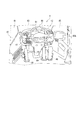
- FIG. 3 shows the structure of the cockpit in the cab 4.
- the cab 4 includes a housing 41 that forms an outer shell, and a front console unit 42 provided in front of the housing 41.
- the housing 41 is provided with a front window 43 at the center, a front left window 44 on the front left side, and a front right window 45 on the front right side to ensure the forward vision of the driver of the wheel loader 1.
- a rear monitor 45A is provided on the right side of the front console unit. Although not shown in the drawings, the rear monitor 45A displays an image of a camera attached to the rear end of the vehicle main body 2 to secure the rear view of the operator of the wheel loader 1.
- the front console unit 42 constitutes a front inner wall of the wheel loader 1 and various devices for operating the wheel loader 1 are provided.
- a steering wheel 46 is rotatably provided at the approximate center of the front console unit 42. When an operator turns the steering wheel 46, the front side of the vehicle body 2 is rotated and the wheel loader 1 can be turned. .
- An operation switch panel 47 is provided on the left side of the steering wheel 46, and by operating the operation switch, the work mode of the wheel loader 1 is changed to a high load work mode in which work load is emphasized, or light load work in which fuel consumption is emphasized. You can switch to mode.
- a state information display device 51 of the wheel loader 1 is provided in front of the steering wheel 46.
- the operator may advance the wheel loader 1 with the bucket 32 of the work machine 3 positioned in the vicinity of the ground, so that the front lower view of the wheel loader 1 is sufficiently secured. Is preferable for safety.
- the size of the front console unit 42 is preferably as small as possible, and accordingly, the size of the status information display device 51 is preferably as small as possible. In particular, in the case of the small and medium wheel loader 1, the size is reduced. It becomes important.
- FIG. 4 shows a front view of the status information display device 51 provided in the cab 4.
- the state information display device 51 is connected to the vehicle controller 52 and the engine controller 53 by electrical wiring.
- the vehicle controller 52 controls the vehicle based on detection values from sensors (not shown) such as a temperature sensor and a pressure sensor provided in a drive circuit such as the transmission 54 and a hydraulic circuit system such as a hydraulic pump.
- the engine controller 53 controls the rotational speed of the engine 55 based on sensor (not shown) values such as a rotational speed sensor and a temperature sensor. Detection values of sensors provided in the vehicle controller 52 and the engine controller 53 are output to the state information display device 51 via electric wiring.
- the status information display device 51 includes an operation switch panel 56, an LED indicator panel 57, and a display panel 58.
- the operation switch panel 56, the LED indicator panel 57, and the display panel 58 may be configured integrally or may be configured separately. Further, the operation switch panel 56 and the LED indicator panel 57 are not necessarily required.
- the operation switch panel 56 is provided with various operation switches.
- the operation switch panel 56 is provided with a wiper switch, an air conditioner switch, a changeover switch for the display panel 58, and the like. Can be switched to a desired state such as an in-vehicle state or a display state of the display panel 58.
- the operation switch panel 56 is provided with a dedicated command that is not normally known to the user.
- a maintenance inspection screen is displayed. It is displayed on the display panel 58.
- the dedicated command is used when performing maintenance and inspection, and is a manufacturer-specific command that is not normally disclosed to the operator of the wheel loader 1.
- the LED indicator panel 57 includes a parking lamp, a right / left turn lamp, a light lighting lamp, etc., and displays a part of the operating state of the wheel loader 1, and when a failure occurs in any part of the wheel loader 1 Turn on the red caution display.
- the display panel 58 is composed of a liquid crystal display panel or the like, and displays a plurality of more detailed statuses than the LED indicator panel 57.
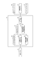
- FIG. 5 shows a functional block diagram of the state information display device 51.
- the status information display device 51 includes a display panel 58 as status information display means and display control means 59.
- the display control unit 59 performs display control of various state information of the wheel loader 1 displayed on the display panel 58 based on detection values of various sensors output from the vehicle controller 52 and the engine controller 53.
- the display control means 59 includes a data transmission / reception unit 60, a standard screen display unit 61, a maintenance inspection screen transition unit 62, a speed information display unit 63, a work mode information display unit 64, and a speed stage information display unit 65. Is provided.
- the data transmission / reception unit 60 receives detection values of various sensors from the vehicle control controller 52 and the engine controller 53, and sends operation switch setting signals performed by the operator through the operation switch panel 56 to the vehicle control controller 52, It outputs to the engine controller 53, and the setting in the vehicle controller 52 and the engine controller 53 is changed.
- the data transmission / reception unit 60 switches the display screen of the display panel 58 based on the switch setting signal set on the operation switch panel 56.
- the standard screen display unit 61 is a part that displays a standard screen representing various state information during the operation of the wheel loader 1, and is based on the information of various sensors received by the data transmission / reception unit 60.
- Display status information Specifically, as shown in FIG. 6, the following status information is displayed on the display panel 58 as a standard screen.
- the hydraulic oil temperature of the hydraulic circuit of the work machine 3 is displayed, and in the area 67 on the lower right, the remaining amount of fuel of the engine is displayed. Further, an engine water temperature is displayed in the upper left area 68, and a torque converter oil temperature is displayed in the lower left area 69.
- the vehicle speed of the wheel loader 1 is displayed, and in the area 71 below it, the time is displayed.
- the actual speed stage of the wheel loader 1 is displayed, and in the area 73 below it is the set speed of the speed change lever (not shown in FIG. 3) provided in the cab 4.
- a column is displayed.
- the area 74 adjacent to the right side displays the remaining amount of urea water in the urea SCR (Selective Catalytic Reduction) system.
- a fuel consumption during operation of the wheel loader 1 is displayed in an area 75 below the area 75. In the region 75, the display information can be changed by operating the operation switch.
- the fuel consumption, the travel distance, the clock, and the service meter are switched and displayed. can do. Further, a service meter is displayed in the left side area 76. Similarly to the area 75, a plurality of pieces of information such as a travel distance, a time, and a service meter can be switched and displayed in this area 76.
- an eco gauge that displays whether or not the wheel loader 1 is operated with energy saving is displayed.
- the setting condition of the air conditioner is displayed, in the area 79, whether or not the seat belt is worn is displayed, and in the area 80, whether the wheel loader 1 is operating in the high load work mode (P mode),
- a pilot lamp corresponding to various settings such as a pilot lamp indicating which of the low-load work mode (E mode) is operating is displayed.
- the maintenance inspection screen transition unit 62 makes a transition from the above-described standard screen to the maintenance inspection screen.
- the trigger for the screen transition is that a special service command (such as operating a plurality of specific switches at the same time) is input using the operation switch panel 56 by a manufacturer serviceman.
- the speed information display unit 63 displays speed information in any area of the maintenance / inspection screen when the maintenance / inspection screen transition unit 62 makes a transition to the maintenance / inspection screen.
- the speed information means a vehicle speed based on a detection value detected by the rotation sensor of the drive wheel 5 ⁇ / b> A and output from the engine controller 53.
- the work mode information display unit 64 indicates whether the wheel loader 1 is operating in the high load work mode (P mode) or the low load work mode (E mode). Display in the area.
- the speed stage information display unit 65 displays the actual speed stage information of the torque converter connected to the engine of the power unit 6 when the maintenance inspection screen transition unit 62 transits to the maintenance inspection screen.
- the speed information display unit 63, the work mode information display unit 64, and the speed stage information display unit 65 have a function of displaying each information not only on the maintenance inspection screen but also on the standard screen.
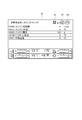
- the maintenance / inspection screen transition unit 62 starts from the standard screen and displays status information in the maintenance / inspection screen shown in FIG. A transition is made to the display screen G1 (step S3). If it determines with having changed to the status information display screen G1 of FIG. 8, the speed information display part 63 will display the speed information 81 on the area
- the maintenance / inspection screen transition unit 62 transitions to the maintenance / inspection sensor adjustment screen G2 shown in FIG. 9 (step S7). If it determines with having changed to the sensor adjustment screen G2 of FIG. 9, the speed information display part 63 will display the speed information 84 on the lower part of the sensor adjustment screen G2 (procedure S4). Further, the work mode information display unit 64 displays the work mode information 85 in the upper right area of the sensor adjustment screen G2 (step S5). Further, the speed stage information display unit 65 displays speed stage information 86 on the right side of the work mode information 85 (step S6). The manufacturer's service person adjusts each part of the wheel loader 1 while checking the speed information 84, the work mode information 85, and the speed stage information 86 on the sensor adjustment screen G2.
- the speed information display unit 63 Since the speed information display unit 63 is provided, the speed information 81 and 84 of the wheel loader 1 can be displayed at the time of transition of the maintenance inspection screens G1 and G2. It is possible to safely perform maintenance and inspection work while checking the speed information. Maintenance inspection work can be performed while checking the operation mode information 82, 85 of the wheel loader 1 on the maintenance inspection screens G1, G2 at the time of transition of the maintenance inspection screens G1, G2. By grasping in detail, the cause of failure can be easily identified.
- Maintenance inspection can be performed while checking the actual speed stage information 83, 86 of the wheel loader 1 on the maintenance inspection screen at the time of transition of the maintenance inspection screen G1, G2. It can be assumed that the speed will be about a certain level, and maintenance inspection work can be performed safely.
- Speed information 81 and 84, work mode information 82 and 85, and actual speed stage information 83 and 86 are displayed on both the state information display screen G1 and the sensor adjustment screen G2, so these information and the like are always checked during maintenance inspection. It is possible to adjust the sensor while driving the wheel loader 1 safely.
- the present invention is not limited to the above-described embodiments, but includes modifications and improvements as long as the object of the present invention can be achieved.
- the wheel-type work vehicle is the wheel loader 1, but the present invention is not limited to this and can be used for various wheel-type work vehicles such as a motor grader, a forklift, and a dump truck.
- the working machine using HST Hydro Static Transmission
- HST Hydro Static Transmission
- the speed information 81 and 84, the work mode information 82 and 85, and the actual speed stage information 83 and 86 are displayed at the corners of the display panel 58, but the information display regarding maintenance and inspection is not hidden. If it is a position, these pieces of information may be displayed at an arbitrary position.
- a dedicated command is input as a predetermined dedicated operation.
- the present invention is not limited to this, and other operations (such as a hidden switch that is not noticed by the operator, an operation using a dedicated terminal or a computer, etc.) ).
Landscapes
- Engineering & Computer Science (AREA)
- Chemical & Material Sciences (AREA)
- Combustion & Propulsion (AREA)
- Transportation (AREA)
- Mechanical Engineering (AREA)
- Civil Engineering (AREA)
- Mining & Mineral Resources (AREA)
- General Engineering & Computer Science (AREA)
- Structural Engineering (AREA)
- Physics & Mathematics (AREA)
- General Physics & Mathematics (AREA)
- Component Parts Of Construction Machinery (AREA)
- Instrument Panels (AREA)
Abstract
Description
なお、保守点検用のモードの中には、上記のような故障診断のための画面だけでなくセンサ等の調整やその他重要な設定を切り替えるための画面も存在するため、サービスマンのみが把握している専用コマンドを状態情報表示装置に入力することにより、保守点検用のモードに切り替えられるようになっており、通常の操作者には保守点検用のモードに切り替えることができないようにしている。
前記ホイール系作業車両の複数の状態情報を表示する状態情報表示手段と、
前記状態情報表示手段の表示制御を行う表示制御手段とを備え、
前記表示制御手段は、
前記ホイール系作業車両の操作中に、前記複数の状態情報を標準画面として表示させる標準画面表示部と、
所定の専用操作によって、前記標準画面から遷移して、前記ホイール系作業車両の保守点検用画面を表示させる保守点検用画面遷移部と、
前記保守点検用画面のいずれかの領域に、前記ホイール系作業車両の速度情報を表示させる速度情報表示部とを備えていることを特徴とする。
前記ホイール系作業車両は、作業負荷を重視した高負荷作業モード、及び燃費を重視した軽負荷作業モードで動作し、
前記保守点検用画面遷移部による画面遷移時に、前記保守点検用画面のいずれかの領域に、前記ホイール系作業車両がいずれの作業モードで動作しているかを表示させる作業モード情報表示部を備えていることを特徴とする。
本発明の第2の態様によれば、保守点検用画面の遷移時に、ホイール系作業車両の作業モード情報を、保守点検用画面上で確認しながら、保守点検作業を行うことができるので、稼働状態をより詳しく把握して、故障原因等の特定を容易に行うことができる。
前記ホイール系作業車両は、エンジン駆動式の作業車両であり、
前記保守点検用画面遷移部による画面遷移時に、前記保守点検用画面のいずれかの領域に、速度段を表示させる速度段情報表示部を備えていることを特徴とする。
本発明の第3の態様によれば、保守点検用画面の遷移時に、ホイール系作業車両速度情報に加えて速度段情報を保守点検用画面上で確認しながら保守点検作業を行うことができるので、稼働状態をより詳しく把握して故障原因等の特定を容易に行うことができる。また、アクセル調整等においても、どの程度の速度となるかを想定することができ、安全に保守点検作業を行うことができる。
前記保守点検用画面遷移部は、前記標準画面に表示させる状態情報とは異なる複数の状態情報を表示する状態情報表示画面と、当該複数の状態情報のうち、いずれかの状態情報に係るセンサの調整を行うためのセンサ調整画面とを切り替え表示可能とし、
前記速度情報表示部は、前記状態情報表示画面及びセンサ調整画面のいずれにも速度情報を表示させることを特徴とする。
本発明の第4の態様によれば、状態情報表示画面及びセンサ調整画面のいずれでも速度情報が表示されるので、保守点検中常に速度情報等を確認することができ、安全にホイール系作業車両を走行させつつ、センサの調整作業を行うことができる。
ホイール系作業車両の複数の状態情報を表示する状態情報表示手段と、前記状態情報表示手段の表示制御を行う表示制御手段と、を備えたホイール系作業車両の保守点検用画面の表示方法であって、
前記表示制御手段は、前記ホイール系作業車両の操作中に、前記複数の状態情報を、標準画面として表示する標準画面表示部と、所定の専用操作によって、前記標準画面から遷移して、前記ホイール系作業車両の保守点検用画面を表示する保守点検用画面遷移部とを備え、
前記保守点検用画面のいずれかの領域に、前記ホイール系作業車両の速度情報を表示する手順を実施することを特徴とする。
ホイール系作業車両の複数の状態情報を表示する状態情報表示手段と、前記状態情報表示手段の表示制御を行う表示制御手段と、を備えたホイール系作業車両の保守点検用画面の表示方法を、前記表示制御手段に実施させるコンピュータ読み取り可能なホイール系作業車両の保守点検用画面表示プログラムであって、
前記表示制御手段に、
前記ホイール系作業車両の操作中に、前記複数の状態情報を、標準画面として表示する手順と、
所定の専用操作によって、前記標準画面から遷移して、前記ホイール系作業車両の保守点検用画面を表示する手順と、
前記保守点検用画面への画面遷移時に、前記保守点検用画面のいずれかの領域に、前記ホイール系作業車両の速度情報を表示する手順とを実施させることを特徴とする。
本発明の第5の態様及び第6の態様によっても、前述と同一の作用及び効果を享受できる。
図1及び図2には、本発明の実施形態に係る作業車両としてのホイールローダー1が示されている。このホイールローダー1は、車両本体2、作業機3、キャブ4、走行装置5、及び動力部6、を備える。
車両本体2は、作業機3、キャブ4、および動力部6を支持する鋼製フレーム体から構成されている。この車両本体2の前方側には、車両本体2に対して左右方向に回転自在に構造体21が設けられ、この構造体21のさらに前方側には、作業機3が設けられている。
ブーム31は、車幅方向に一対配置され、構造体21に対して上下に回動自在に枢軸されている。このブーム31の中間部には、リフトシリンダ(図示略)が枢軸され、リフトシリンダの基端部分は、構造体21に枢軸されている。そして、このリフトシリンダを油圧によって伸縮させることにより、ブーム31が上下に回動するようになっている。
ベルクランク33は、一対のブーム31の間に枢軸され、下端は前記リンクの基端部分が接続されている。ベルクランク33の上端には、チルトシリンダ36が枢軸され、このチルトシリンダ36の基端部分は、前記構造体21に枢軸されている。
図3には、キャブ4内の操縦席の構造が示されている。
キャブ4は、外郭を構成する筐体41と、筐体41内の前方に設けられたフロントコンソールユニット42とを備える。
筐体41には、中央に前窓43、前方左側に前左窓44、前方右側に前右窓45が取り付けられ、ホイールローダー1の操縦者の前方視覚を確保している。また、フロントコンソールユニット42の右側には、後方モニター45Aが設けられている。この後方モニター45Aには、図示を略したが、車両本体2の後端に取り付けられたカメラの映像を映し出し、ホイールローダー1の操縦者の後方視界を確保する。
フロントコンソールユニット42の略中央には、ステアリングホイール46が回動自在に設けられ、操作者がステアリングホイール46を回すと、車両本体2の前方側が回動し、ホイールローダー1を旋回させることができる。
ステアリングホイール46の左側には、操作スイッチパネル47が設けられ、操作スイッチを操作することにより、ホイールローダー1の作業モードを、作業負荷を重視した高負荷作業モード、又は燃費を重視した軽負荷作業モードに切り替え設定することができる。
そして、ステアリングホイール46の前方には、ホイールローダー1の状態情報表示装置51が設けられている。
このようなキャブ4では、操作者が作業機3のバケット32を地上近傍に位置させた状態でホイールローダー1を前進させることがあるので、ホイールローダー1の前下方視界を十分確保されているのが安全上好ましい。従って、フロントコンソールユニット42の大きさは、なるべく小さい方が好ましく、これに伴い、状態情報表示装置51の大きさもなるべく小さくした方がよく、特に中小型のホイールローダー1の場合は、小型化することが重要となる。
図4には、キャブ4内に設けられた状態情報表示装置51の正面図が示されている。
状態情報表示装置51は、車両制御コントローラ52及びエンジンコントローラ53と電気的配線によって接続されている。車両制御コントローラ52は、トランスミッション54といった駆動系や油圧ポンプといった油圧回路系に設けられた温度センサや圧力センサ等のセンサ類(図示略)からの検出値に基づいて、車両の制御を行う。エンジンコントローラ53は、回転速度センサ、温度センサ等のセンサ類(図示略)値に基づいて、エンジン55の回転数を制御する。
車両制御コントローラ52及びエンジンコントローラ53に設けられたセンサ類の検出値は、電気配線を介して状態情報表示装置51に出力される。
操作スイッチパネル56には種々の操作スイッチが設けられ、操作スイッチパネル56には、ワイパースイッチや、エアコンスイッチ、表示パネル58の切替スイッチ等が設けられ、操作者はこの操作スイッチパネル56の操作スイッチを操作することにより、車内の状態、表示パネル58の表示状態等所望の状態に切り替えることができる。
尚、操作スイッチパネル56には、通常ユーザーには知らされない専用コマンドが設けられており、詳しくは後述するが、メーカーのサービスマンである保守点検者が、隠しコマンドを打ち込むと保守点検用画面が表示パネル58に表示されるようになっている。専用コマンドは保守点検を行う際に用いられるものであり、ホイールローダー1の操作者には通常開示されないメーカー独自のものである。
表示パネル58は、液晶表示パネル等から構成され、LEDインジケータパネル57よりもより詳細な複数の状態表示を行う。
表示制御手段59は、データ送受信部60と、標準画面表示部61と、保守点検用画面遷移部62と、速度情報表示部63と、作業モード情報表示部64と、速度段情報表示部65とを備える。
具体的には、図6に示すように、表示パネル58には、次のような状態情報が標準画面として表示される。
まず、表示パネル58の四隅には、エンジンや駆動系、ポンプの温度に関する情報が表示される。表示パネル58の右上にある領域66には、作業機3の油圧回路の作動油温が表示され、右下にある領域67には、エンジンの燃料残量が表示される。
また、左上にある領域68には、エンジン水温が表示され、左下領域69には、トルクコンバータ油温が表示される。
車速表示の右側にある領域72には、ホイールローダー1の実速度段が表示され、その下にある領域73には、キャブ4内に設けられた変速レバー(図3では図示略)の設定速度段が表示される。さらに、その右側に隣接する領域74には、尿素SCR(Selective Catalytic Reduction)システムの尿素水残量が表示される。
その下部にある領域75には、ホイールローダー1の稼働中の燃費が表示される。尚、領域75は操作スイッチを操作することにより、表示情報を変更させることができるようになっており、本実施形態では、燃費、走行距離、時計、サービスメーター(エンジン稼働時間)を切り替えて表示することができる。また、その左側領域76には、サービスメーターが表示されるが、この領域76も、領域75と同様に複数の情報、例えば走行距離、時刻、サービスメーターを切替表示できるようになっている。
領域78には、エアーコンディショナーの設定状態が表示され、領域79にはシートベルト装着の有無が表示され、領域80には、ホイールローダー1が高負荷作業モード(Pモード)で動作しているか、低負荷作業モード(Eモード)のいずれで動作しているかを示すパイロットランプ等、種々の設定に応じたパイロットランプが表示される。
速度情報表示部63は、保守点検用画面遷移部62で保守点検用画面に遷移した際に、保守点検用画面のいずれかの領域に速度情報を表示させる。速度情報は、駆動輪5Aの回転センサで検出され、エンジンコントローラ53から出力された検出値に基づく車速を意味する。
速度段情報表示部65は、保守点検用画面遷移部62で保守点検用画面に遷移した際に、動力部6のエンジンに接続されたトルクコンバータの実速度段情報を表示させる。
なお、速度情報表示部63、作業モード情報表示部64および速度段情報表示部65は、保守点検用画面だけでなく、標準画面においても各情報を表示させる機能を果たしている。
次に、本実施形態の作用を図7に示されるフローチャートに基づいて説明する。尚、図7に示されるフローチャートは、コンピュータ等のプログラムとして構成され、表示制御手段59上で実行される。
ホイールローダー1の稼働中、標準画面表示部61は、前述した図6に示される標準画面を表示して、操作者にホイールローダー1の各種状態情報を視認させる(手順S1)。
標準画面表示部61は、データ送受信部60を介して、操作スイッチパネル56から専用コマンドが入力されたか否かを監視する(手順S2)。
図8の状態情報表示画面G1に遷移したと判定されたら、速度情報表示部63は、右上の領域に速度情報81を表示させる(手順S4)。
同時に作業モード情報表示部64は、速度情報81の右に作業モード情報82を表示させる(手順S5)。
さらに、速度段情報表示部65は、作業モード情報82の右に実速度段情報83を表示させる(手順S6)。
図9のセンサ調整画面G2に遷移したと判定されたら、速度情報表示部63は、センサ調整画面G2の下部に速度情報84を表示させる(手順S4)。
また、作業モード情報表示部64は、センサ調整画面G2の右上の領域に作業モード情報85を表示させる(手順S5)。
さらに、速度段情報表示部65は、作業モード情報85の右に速度段情報86を表示させる(手順S6)
メーカーのサービスマンは、センサ調整画面G2上で、速度情報84、作業モード情報85、速度段情報86を確認しながら、ホイールローダー1の各部位の調整を行う。
速度情報表示部63を備えていることにより、保守点検用画面G1、G2の遷移時に、ホイールローダー1の速度情報81、84を表示させることができるので、メーカーのサービスマンは、ホイール系作業車両を走行させ、速度情報を確認しながら、安全に保守点検作業を行うことができる。
保守点検用画面G1、G2の遷移時に、ホイールローダー1の作業モード情報82、85を、保守点検用画面G1、G2上で確認しながら、保守点検作業を行うことができるので、稼働状態をより詳しく把握して、故障原因等の特定を容易に行うことができる。
状態情報表示画面G1及びセンサ調整画面G2のいずれでも速度情報81、84、作業モード情報82、85、実速度段情報83、86が表示されるので、保守点検中常にこれらの情報等を確認することができ、安全にホイールローダー1を走行させつつ、センサの調整作業を行うことができる。
なお、本発明は前述の実施形態に限定されるものではなく、本発明の目的を達成できる範囲での変形、改良等は本発明に含まれるものである。
例えば、前記実施形態では、ホイール式作業車両をホイールローダー1としていたが、本発明はこれに限らず、モーターグレーダー、フォークリフト、ダンプトラック等種々のホイール系作業車両に利用することができる。
さらに、前記実施形態では、トルクコンバータを用いた作業機械としていたが、HST(Hydro Static Transmission)を用いた作業機械であってもよい。
また、前記実施形態では、表示パネル58の角隅部に速度情報81、84、作業モード情報82、85、実速度段情報83、86を表示していたが、保守点検に関する情報表示を隠蔽しない位置であれば、任意の位置にこれらの情報を表示させるようにしてもよい。
また、前記実施形態では、所定の専用操作として専用コマンドを入力していたが、本発明はこれに限らず、その他の操作(オペレータに気づかれない隠しスイッチ、専用端末やコンピュータを用いた操作等)であってもよい。
Claims (6)
- ホイール系作業車両の複数の状態情報を表示する状態情報表示手段と、
前記状態情報表示手段の表示制御を行う表示制御手段とを備え、
前記表示制御手段は、
前記ホイール系作業車両の操作中に、前記複数の状態情報を標準画面として表示させる標準画面表示部と、
所定の専用操作によって、前記標準画面から遷移して、前記ホイール系作業車両の保守点検用画面を表示させる保守点検用画面遷移部と、
前記保守点検用画面のいずれかの領域に、前記ホイール系作業車両の速度情報を表示させる速度情報表示部とを備えていることを特徴とするホイール系作業車両の状態情報表示装置。 - 請求項1に記載のホイール系作業車両の状態情報表示装置において、
前記ホイール系作業車両は、作業負荷を重視した高負荷作業モード、及び燃費を重視した軽負荷作業モードで動作し、
前記保守点検用画面遷移部による画面遷移時に、前記保守点検用画面のいずれかの領域に、前記ホイール系作業車両がいずれの作業モードで動作しているかを表示させる作業モード情報表示部を備えていることを特徴とする状態情報表示装置。 - 請求項1又は請求項2に記載のホイール系作業車両の状態情報表示装置において、
前記ホイール系作業車両は、エンジン駆動式の作業車両であり、
前記保守点検用画面遷移部による画面遷移時に、前記保守点検用画面のいずれかの領域に、速度段を表示させる速度段情報表示部を備えていることを特徴とするホイール系作業車両の状態情報表示装置。 - 請求項1乃至請求項3のいずれか一項に記載のホイール系作業車両の状態情報表示装置において、
前記保守点検用画面遷移部は、前記標準画面に表示させる状態情報とは異なる複数の状態情報を表示する状態情報表示画面と、当該複数の状態情報のうち、いずれかの状態情報に係るセンサの調整を行うためのセンサ調整画面とを切替表示可能とし、
前記速度情報表示部は、前記状態情報表示画面及びセンサ調整画面のいずれにも速度情報を表示させることを特徴とするホイール系作業車両の状態情報表示装置。 - ホイール系作業車両の複数の状態情報を表示する状態情報表示手段と、前記状態情報表示手段の表示制御を行う表示制御手段と、を備えたホイール系作業車両の保守点検用画面の表示方法であって、
前記表示制御手段は、
前記ホイール系作業車両の操作中に、前記複数の状態情報を、標準画面として表示する標準画面表示部と、
所定の専用操作によって、前記標準画面から遷移して、前記ホイール系作業車両の保守点検用画面を表示する保守点検用画面遷移部とを備え、
前記保守点検用画面のいずれかの領域に、前記ホイール系作業車両の速度情報を表示する手順を実施することを特徴とするホイール系作業車両の保守点検用画面の表示方法。 - ホイール系作業車両の複数の状態情報を表示する状態情報表示手段と、前記状態情報表示手段の表示制御を行う表示制御手段と、を備えたホイール系作業車両の保守点検用画面の表示方法を、前記表示制御手段に実施させるコンピュータ読み取り可能なホイール系作業車両の保守点検用画面表示プログラムであって、
前記表示制御手段に、
前記ホイール系作業車両の操作中に、前記複数の状態情報を、標準画面として表示する手順と、
所定の専用操作によって、前記標準画面から遷移して、前記ホイール系作業車両の保守点検用画面を表示する手順と、
前記保守点検用画面への画面遷移時に、前記保守点検用画面のいずれかの領域に、前記ホイール系作業車両の速度情報を表示する手順とを実施させることを特徴とするホイール系作業車両の保守点検用画面表示プログラム。
Priority Applications (4)
| Application Number | Priority Date | Filing Date | Title |
|---|---|---|---|
| JP2015531384A JP6022694B2 (ja) | 2014-12-26 | 2014-12-26 | ホイール系作業車両の状態情報表示装置、ホイール系作業車両の保守点検用画面の表示方法、及びホイール系作業車両の保守点検用画面表示プログラム |
| PCT/JP2014/084676 WO2015088049A1 (ja) | 2014-12-26 | 2014-12-26 | ホイール系作業車両の状態情報表示装置、ホイール系作業車両の保守点検用画面の表示方法、及びホイール系作業車両の保守点検用画面表示プログラム |
| CN201480010616.5A CN105026655B (zh) | 2014-12-26 | 2014-12-26 | 轮式作业车辆的状态信息显示装置、维护用画面的显示方法 |
| US14/763,256 US10026242B2 (en) | 2014-12-26 | 2014-12-26 | Status information display device for wheeled work vehicle, maintenance-screen display method for wheeled work vehicle, and maintenance-screen display program for wheeled work vehicle |
Applications Claiming Priority (1)
| Application Number | Priority Date | Filing Date | Title |
|---|---|---|---|
| PCT/JP2014/084676 WO2015088049A1 (ja) | 2014-12-26 | 2014-12-26 | ホイール系作業車両の状態情報表示装置、ホイール系作業車両の保守点検用画面の表示方法、及びホイール系作業車両の保守点検用画面表示プログラム |
Publications (1)
| Publication Number | Publication Date |
|---|---|
| WO2015088049A1 true WO2015088049A1 (ja) | 2015-06-18 |
Family
ID=53371341
Family Applications (1)
| Application Number | Title | Priority Date | Filing Date |
|---|---|---|---|
| PCT/JP2014/084676 Ceased WO2015088049A1 (ja) | 2014-12-26 | 2014-12-26 | ホイール系作業車両の状態情報表示装置、ホイール系作業車両の保守点検用画面の表示方法、及びホイール系作業車両の保守点検用画面表示プログラム |
Country Status (4)
| Country | Link |
|---|---|
| US (1) | US10026242B2 (ja) |
| JP (1) | JP6022694B2 (ja) |
| CN (1) | CN105026655B (ja) |
| WO (1) | WO2015088049A1 (ja) |
Cited By (1)
| Publication number | Priority date | Publication date | Assignee | Title |
|---|---|---|---|---|
| JP2018035558A (ja) * | 2016-08-31 | 2018-03-08 | 株式会社小松製作所 | ホイールローダ及びアダプタ |
Families Citing this family (2)
| Publication number | Priority date | Publication date | Assignee | Title |
|---|---|---|---|---|
| WO2020003948A1 (ja) * | 2018-06-29 | 2020-01-02 | 株式会社クボタ | 作業機 |
| EP3961221B1 (en) * | 2019-04-24 | 2025-05-28 | Hitachi High-Tech Corporation | Automatic analysis device and maintenance guide method in automatic analysis device |
Citations (2)
| Publication number | Priority date | Publication date | Assignee | Title |
|---|---|---|---|---|
| JP2002327467A (ja) * | 2001-05-02 | 2002-11-15 | Komatsu Ltd | 作業機械の表示装置 |
| JP2014190091A (ja) * | 2013-03-27 | 2014-10-06 | Sumitomo (Shi) Construction Machinery Co Ltd | ショベル |
Family Cites Families (22)
| Publication number | Priority date | Publication date | Assignee | Title |
|---|---|---|---|---|
| US7489303B1 (en) * | 2001-02-22 | 2009-02-10 | Pryor Timothy R | Reconfigurable instrument panels |
| JP5162782B2 (ja) | 2000-08-07 | 2013-03-13 | 株式会社小松製作所 | 作業機械の表示装置 |
| CN2559688Y (zh) | 2002-04-15 | 2003-07-09 | 广西柳工机械股份有限公司 | 组合式智能化仪表板 |
| US20050038579A1 (en) * | 2003-08-15 | 2005-02-17 | Lewis Michael W. | Interactive maintenance management alarm handling |
| JP4758087B2 (ja) * | 2004-09-27 | 2011-08-24 | アルパイン株式会社 | 表示装置 |
| CN2784469Y (zh) | 2005-04-29 | 2006-05-31 | 上海三一科技有限公司 | 挖掘装载机仪表板总成 |
| JP4498302B2 (ja) | 2006-04-05 | 2010-07-07 | 日立建機株式会社 | ホイール式作業機械の表示装置 |
| US20100169821A1 (en) * | 2007-05-29 | 2010-07-01 | Teruhisa Masui | Layout switching device, screen generating device for moving object,information display system for moving object,moving object,and control method |
| JP2009154647A (ja) * | 2007-12-26 | 2009-07-16 | Aisin Aw Co Ltd | マルチ画面表示装置及びそのプログラム |
| JP4769265B2 (ja) * | 2008-03-31 | 2011-09-07 | 株式会社クボタ | 作業車の作業条件表示構造 |
| JP4768057B2 (ja) * | 2009-08-06 | 2011-09-07 | シャープ株式会社 | コンテンツ視聴装置及びコンテンツ表示装置 |
| CN102656324B (zh) | 2009-12-18 | 2013-03-27 | 株式会社小松制作所 | 作业车辆的监控装置 |
| JP5363407B2 (ja) | 2010-04-26 | 2013-12-11 | 日立建機株式会社 | 建設機械の表示装置 |
| US20130166998A1 (en) * | 2011-12-23 | 2013-06-27 | Patrick Sutherland | Geographically-referenced Video Asset Mapping |
| JP5963571B2 (ja) * | 2012-06-28 | 2016-08-03 | キヤノン株式会社 | 画像表示装置及び監視カメラシステム |
| JP5805692B2 (ja) | 2013-03-21 | 2015-11-04 | 日立建機株式会社 | ホイール式作業機械 |
| JP6197524B2 (ja) * | 2013-09-19 | 2017-09-20 | トヨタ自動車株式会社 | 4輪駆動車両の制御装置 |
| JP6295924B2 (ja) * | 2014-03-18 | 2018-03-20 | 株式会社デンソー | 車両用報知制御装置、及び車両用報知制御システム |
| US20170108702A1 (en) * | 2014-07-14 | 2017-04-20 | Cinema2Go Ltd. | Near-eye display system |
| US9930308B2 (en) * | 2014-07-26 | 2018-03-27 | Clipchamp Ip Pty Ltd | Platform-agnostic video player for mobile computing devices and desktop computers |
| CN104598111B (zh) * | 2015-01-15 | 2018-10-02 | 小米科技有限责任公司 | 切换显示模式的方法及装置 |
| JP6700775B2 (ja) * | 2015-12-22 | 2020-05-27 | キヤノン株式会社 | 電子機器及びその制御方法 |
-
2014
- 2014-12-26 WO PCT/JP2014/084676 patent/WO2015088049A1/ja not_active Ceased
- 2014-12-26 JP JP2015531384A patent/JP6022694B2/ja active Active
- 2014-12-26 CN CN201480010616.5A patent/CN105026655B/zh active Active
- 2014-12-26 US US14/763,256 patent/US10026242B2/en active Active
Patent Citations (2)
| Publication number | Priority date | Publication date | Assignee | Title |
|---|---|---|---|---|
| JP2002327467A (ja) * | 2001-05-02 | 2002-11-15 | Komatsu Ltd | 作業機械の表示装置 |
| JP2014190091A (ja) * | 2013-03-27 | 2014-10-06 | Sumitomo (Shi) Construction Machinery Co Ltd | ショベル |
Cited By (1)
| Publication number | Priority date | Publication date | Assignee | Title |
|---|---|---|---|---|
| JP2018035558A (ja) * | 2016-08-31 | 2018-03-08 | 株式会社小松製作所 | ホイールローダ及びアダプタ |
Also Published As
| Publication number | Publication date |
|---|---|
| CN105026655B (zh) | 2017-09-29 |
| CN105026655A (zh) | 2015-11-04 |
| JP6022694B2 (ja) | 2016-11-09 |
| JPWO2015088049A1 (ja) | 2017-03-16 |
| US20160189448A1 (en) | 2016-06-30 |
| US10026242B2 (en) | 2018-07-17 |
Similar Documents
| Publication | Publication Date | Title |
|---|---|---|
| JP5337220B2 (ja) | 作業機械の表示装置および表示装置を搭載した作業機械 | |
| JP6067858B2 (ja) | 作業機械の状態情報表示装置、作業機械の警告表示方法、及び作業機械の警告表示プログラム | |
| CN103210154B (zh) | 建筑机械的信息显示装置、建筑机械的信息显示方法 | |
| CN102180428B (zh) | 小型多功能越野叉车 | |
| CN111788360A (zh) | 作业车辆 | |
| JP2015040422A (ja) | 建設機械の表示装置 | |
| US20160060847A1 (en) | Operator assistance system for machine | |
| JP2014240205A (ja) | ジョイスティック操舵車両 | |
| JP6022694B2 (ja) | ホイール系作業車両の状態情報表示装置、ホイール系作業車両の保守点検用画面の表示方法、及びホイール系作業車両の保守点検用画面表示プログラム | |
| KR101747274B1 (ko) | 휠식 작업 기계 | |
| CA3099784C (en) | Hydraulic drive control | |
| JPWO2018179113A1 (ja) | 作業車両 | |
| WO2016067986A1 (ja) | 作業車両 | |
| JP2019206873A (ja) | ホイール式作業機械 | |
| JP2011157751A (ja) | 油圧作業機 | |
| JP6789880B2 (ja) | 作業機の状態管理システム | |
| CN105189155B (zh) | 用于操作移动式挖掘机的行车制动器并锁定其摆动轴的装置 | |
| WO2016189634A1 (ja) | 作業機械の出力装置及び作業機械の出力方法 | |
| KR102461072B1 (ko) | 건설기계의 오토 아이들 제어 장치 및 방법 | |
| JP6807289B2 (ja) | 建設機械 | |
| KR20170077537A (ko) | 작업기계의 유압모터 제어 시스템 및 방법 | |
| US10415656B2 (en) | Work-machine erroneous forward/backward travelling operation notifying device | |
| CN111055682A (zh) | 一种操纵室控制车辆行驶装置 | |
| JP2010220448A (ja) | 四輪駆動式産業用車両 | |
| JP2014199079A (ja) | ホイールローダ |
Legal Events
| Date | Code | Title | Description |
|---|---|---|---|
| WWE | Wipo information: entry into national phase |
Ref document number: 201480010616.5 Country of ref document: CN |
|
| ENP | Entry into the national phase |
Ref document number: 2015531384 Country of ref document: JP Kind code of ref document: A |
|
| WWE | Wipo information: entry into national phase |
Ref document number: 14763256 Country of ref document: US |
|
| 121 | Ep: the epo has been informed by wipo that ep was designated in this application |
Ref document number: 14870408 Country of ref document: EP Kind code of ref document: A1 |
|
| NENP | Non-entry into the national phase |
Ref country code: DE |
|
| 122 | Ep: pct application non-entry in european phase |
Ref document number: 14870408 Country of ref document: EP Kind code of ref document: A1 |