WO2015087908A1 - スクロール型流体機械 - Google Patents
スクロール型流体機械 Download PDFInfo
- Publication number
- WO2015087908A1 WO2015087908A1 PCT/JP2014/082668 JP2014082668W WO2015087908A1 WO 2015087908 A1 WO2015087908 A1 WO 2015087908A1 JP 2014082668 W JP2014082668 W JP 2014082668W WO 2015087908 A1 WO2015087908 A1 WO 2015087908A1
- Authority
- WO
- WIPO (PCT)
- Prior art keywords
- scroll
- expansion
- movable scroll
- back pressure
- chamber
- Prior art date
- Legal status (The legal status is an assumption and is not a legal conclusion. Google has not performed a legal analysis and makes no representation as to the accuracy of the status listed.)
- Ceased
Links
Images










Classifications
-
- F—MECHANICAL ENGINEERING; LIGHTING; HEATING; WEAPONS; BLASTING
- F04—POSITIVE - DISPLACEMENT MACHINES FOR LIQUIDS; PUMPS FOR LIQUIDS OR ELASTIC FLUIDS
- F04C—ROTARY-PISTON, OR OSCILLATING-PISTON, POSITIVE-DISPLACEMENT MACHINES FOR LIQUIDS; ROTARY-PISTON, OR OSCILLATING-PISTON, POSITIVE-DISPLACEMENT PUMPS
- F04C18/00—Rotary-piston pumps specially adapted for elastic fluids
- F04C18/02—Rotary-piston pumps specially adapted for elastic fluids of arcuate-engagement type, i.e. with circular translatory movement of co-operating members, each member having the same number of teeth or tooth-equivalents
- F04C18/0207—Rotary-piston pumps specially adapted for elastic fluids of arcuate-engagement type, i.e. with circular translatory movement of co-operating members, each member having the same number of teeth or tooth-equivalents both members having co-operating elements in spiral form
- F04C18/0215—Rotary-piston pumps specially adapted for elastic fluids of arcuate-engagement type, i.e. with circular translatory movement of co-operating members, each member having the same number of teeth or tooth-equivalents both members having co-operating elements in spiral form where only one member is moving
-
- F—MECHANICAL ENGINEERING; LIGHTING; HEATING; WEAPONS; BLASTING
- F01—MACHINES OR ENGINES IN GENERAL; ENGINE PLANTS IN GENERAL; STEAM ENGINES
- F01C—ROTARY-PISTON OR OSCILLATING-PISTON MACHINES OR ENGINES
- F01C1/00—Rotary-piston machines or engines
- F01C1/02—Rotary-piston machines or engines of arcuate-engagement type, i.e. with circular translatory movement of co-operating members, each member having the same number of teeth or tooth-equivalents
- F01C1/0207—Rotary-piston machines or engines of arcuate-engagement type, i.e. with circular translatory movement of co-operating members, each member having the same number of teeth or tooth-equivalents both members having co-operating elements in spiral form
- F01C1/0215—Rotary-piston machines or engines of arcuate-engagement type, i.e. with circular translatory movement of co-operating members, each member having the same number of teeth or tooth-equivalents both members having co-operating elements in spiral form where only one member is moving
-
- F—MECHANICAL ENGINEERING; LIGHTING; HEATING; WEAPONS; BLASTING
- F01—MACHINES OR ENGINES IN GENERAL; ENGINE PLANTS IN GENERAL; STEAM ENGINES
- F01C—ROTARY-PISTON OR OSCILLATING-PISTON MACHINES OR ENGINES
- F01C1/00—Rotary-piston machines or engines
- F01C1/02—Rotary-piston machines or engines of arcuate-engagement type, i.e. with circular translatory movement of co-operating members, each member having the same number of teeth or tooth-equivalents
- F01C1/0207—Rotary-piston machines or engines of arcuate-engagement type, i.e. with circular translatory movement of co-operating members, each member having the same number of teeth or tooth-equivalents both members having co-operating elements in spiral form
- F01C1/0246—Details concerning the involute wraps or their base, e.g. geometry
- F01C1/0253—Details concerning the base
-
- F—MECHANICAL ENGINEERING; LIGHTING; HEATING; WEAPONS; BLASTING
- F01—MACHINES OR ENGINES IN GENERAL; ENGINE PLANTS IN GENERAL; STEAM ENGINES
- F01C—ROTARY-PISTON OR OSCILLATING-PISTON MACHINES OR ENGINES
- F01C1/00—Rotary-piston machines or engines
- F01C1/02—Rotary-piston machines or engines of arcuate-engagement type, i.e. with circular translatory movement of co-operating members, each member having the same number of teeth or tooth-equivalents
- F01C1/0207—Rotary-piston machines or engines of arcuate-engagement type, i.e. with circular translatory movement of co-operating members, each member having the same number of teeth or tooth-equivalents both members having co-operating elements in spiral form
- F01C1/0246—Details concerning the involute wraps or their base, e.g. geometry
- F01C1/0269—Details concerning the involute wraps
- F01C1/0276—Different wall heights
-
- F—MECHANICAL ENGINEERING; LIGHTING; HEATING; WEAPONS; BLASTING
- F01—MACHINES OR ENGINES IN GENERAL; ENGINE PLANTS IN GENERAL; STEAM ENGINES
- F01C—ROTARY-PISTON OR OSCILLATING-PISTON MACHINES OR ENGINES
- F01C11/00—Combinations of two or more machines or engines, each being of rotary-piston or oscillating-piston type
- F01C11/002—Combinations of two or more machines or engines, each being of rotary-piston or oscillating-piston type of similar working principle
-
- F—MECHANICAL ENGINEERING; LIGHTING; HEATING; WEAPONS; BLASTING
- F01—MACHINES OR ENGINES IN GENERAL; ENGINE PLANTS IN GENERAL; STEAM ENGINES
- F01C—ROTARY-PISTON OR OSCILLATING-PISTON MACHINES OR ENGINES
- F01C19/00—Sealing arrangements in rotary-piston machines or engines
- F01C19/08—Axially-movable sealings for working fluids
-
- F—MECHANICAL ENGINEERING; LIGHTING; HEATING; WEAPONS; BLASTING
- F04—POSITIVE - DISPLACEMENT MACHINES FOR LIQUIDS; PUMPS FOR LIQUIDS OR ELASTIC FLUIDS
- F04C—ROTARY-PISTON, OR OSCILLATING-PISTON, POSITIVE-DISPLACEMENT MACHINES FOR LIQUIDS; ROTARY-PISTON, OR OSCILLATING-PISTON, POSITIVE-DISPLACEMENT PUMPS
- F04C23/00—Combinations of two or more pumps, each being of rotary-piston or oscillating-piston type, specially adapted for elastic fluids; Pumping installations specially adapted for elastic fluids; Multi-stage pumps specially adapted for elastic fluids
- F04C23/001—Combinations of two or more pumps, each being of rotary-piston or oscillating-piston type, specially adapted for elastic fluids; Pumping installations specially adapted for elastic fluids; Multi-stage pumps specially adapted for elastic fluids of similar working principle
- F04C23/003—Combinations of two or more pumps, each being of rotary-piston or oscillating-piston type, specially adapted for elastic fluids; Pumping installations specially adapted for elastic fluids; Multi-stage pumps specially adapted for elastic fluids of similar working principle having complementary function
-
- F—MECHANICAL ENGINEERING; LIGHTING; HEATING; WEAPONS; BLASTING
- F04—POSITIVE - DISPLACEMENT MACHINES FOR LIQUIDS; PUMPS FOR LIQUIDS OR ELASTIC FLUIDS
- F04C—ROTARY-PISTON, OR OSCILLATING-PISTON, POSITIVE-DISPLACEMENT MACHINES FOR LIQUIDS; ROTARY-PISTON, OR OSCILLATING-PISTON, POSITIVE-DISPLACEMENT PUMPS
- F04C23/00—Combinations of two or more pumps, each being of rotary-piston or oscillating-piston type, specially adapted for elastic fluids; Pumping installations specially adapted for elastic fluids; Multi-stage pumps specially adapted for elastic fluids
- F04C23/02—Pumps characterised by combination with, or adaptation to, specific driving engines or motors
-
- F—MECHANICAL ENGINEERING; LIGHTING; HEATING; WEAPONS; BLASTING
- F04—POSITIVE - DISPLACEMENT MACHINES FOR LIQUIDS; PUMPS FOR LIQUIDS OR ELASTIC FLUIDS
- F04C—ROTARY-PISTON, OR OSCILLATING-PISTON, POSITIVE-DISPLACEMENT MACHINES FOR LIQUIDS; ROTARY-PISTON, OR OSCILLATING-PISTON, POSITIVE-DISPLACEMENT PUMPS
- F04C27/00—Sealing arrangements in rotary-piston pumps specially adapted for elastic fluids
- F04C27/005—Axial sealings for working fluid
-
- F—MECHANICAL ENGINEERING; LIGHTING; HEATING; WEAPONS; BLASTING
- F04—POSITIVE - DISPLACEMENT MACHINES FOR LIQUIDS; PUMPS FOR LIQUIDS OR ELASTIC FLUIDS
- F04C—ROTARY-PISTON, OR OSCILLATING-PISTON, POSITIVE-DISPLACEMENT MACHINES FOR LIQUIDS; ROTARY-PISTON, OR OSCILLATING-PISTON, POSITIVE-DISPLACEMENT PUMPS
- F04C2240/00—Components
- F04C2240/80—Other components
- F04C2240/806—Pipes for fluids; Fittings therefor
-
- F—MECHANICAL ENGINEERING; LIGHTING; HEATING; WEAPONS; BLASTING
- F25—REFRIGERATION OR COOLING; COMBINED HEATING AND REFRIGERATION SYSTEMS; HEAT PUMP SYSTEMS; MANUFACTURE OR STORAGE OF ICE; LIQUEFACTION SOLIDIFICATION OF GASES
- F25B—REFRIGERATION MACHINES, PLANTS OR SYSTEMS; COMBINED HEATING AND REFRIGERATION SYSTEMS; HEAT PUMP SYSTEMS
- F25B2400/00—Component parts or details not otherwise provided for in this subclass
- F25B2400/14—Power generation using energy from the expansion of the refrigerant
Definitions
- the present invention relates to a scroll type fluid machine having an inflating portion composed of fixed and movable scrolls.
- This type of scroll type fluid machine includes a scroll unit including a movable scroll provided with a lap on the base surface and a fixed scroll provided with a wrap meshing with the lap of the movable scroll on the base surface.
- a single plate type compressor-integrated expander in which a working chamber of a unit is divided into a compression chamber and an expansion chamber by a partition wall to form a compression portion and an expansion portion is known (for example, see Patent Document 1).
- FIG. 15 is an enlarged view of the scroll unit 100 portion of Patent Document 1.
- An annular intermediate partition wall (annular wall) 152 and an annular outer partition wall 154 are erected on the base surface of the fixed scroll 108, and a spiral shape is formed between the intermediate partition wall 152 and the outer partition wall 154.
- a spiral inner fixed scroll wrap (wrap) 158 is erected on the center side of the outer fixed scroll wrap (wrap) 156 and the intermediate partition wall 52.
- a compression side suction chamber 138 is formed at the outer peripheral end of the compression portion 104 inside the outer partition wall 154, and the compression side discharge is discharged at the inner peripheral end of the compression portion 104 outside the intermediate partition wall 152.
- a hole 144 is formed.
- the expansion side discharge chamber 132 is formed on the outer peripheral end of the expansion portion 102 inside the intermediate partition wall 152, and the expansion side suction chamber 130 is formed in the central portion that is the inner peripheral end of the expansion portion 102 on the substrate 108 ⁇ / b> A. ing.
- a spiral outer movable scroll wrap (wrap) 164 that meshes with the outer fixed scroll wrap 156 and a spiral inner movable scroll wrap (wrap) that meshes with the inner fixed scroll wrap 158. It is erected in the direction of the spiral opposite to 166.
- the expansion portion 102 is formed inside the intermediate partition wall 152, and the compression portion 104 is formed between the intermediate partition wall 152 and the outer partition wall 154.
- the working fluid maintained at a high pressure compressed by a high-stage compressor (not shown) is sucked from the expansion-side suction chamber 130, and is expanded in the expansion chamber formed between the wraps 158 and 166 of the expansion portion 102.
- a high-stage compressor By expanding, the movable scroll 110 is revolved and the power is recovered. With this power, the working fluid is compressed in a compression chamber formed between the wraps 156 and 164 of the compression unit 104.
- the compression unit 104 is on the low stage side, and the working fluid compressed by the compression unit 104 is sucked into the high stage side compressor.
- a back pressure chamber 168 is formed on the back side of the movable scroll 110.
- the back pressure chamber 168 is supplied with the working fluid maintained at the discharge pressure of the compression unit 104, and the movable scroll 110 is pressed against the fixed scroll 108 by the pressure.
- JP 2012-52527 A Japanese Patent No. 4940630
- the back pressure chamber 168 of the movable scroll 110 (the whole corresponding to the expansion portion 102 and the compression portion 104) is set as the discharge pressure of the compression portion 104.
- the discharge pressure of the high-stage compressor is applied to the center of the base surface of the movable scroll 110.
- the magnitude relationship between the pressures is indicated by arrows in FIG. In this figure, the length of the arrow indicates the magnitude of pressure (hereinafter the same).
- the back pressure chamber 168 is partitioned into a central part and an outer peripheral part by a sealing member as in Patent Document 2, and the suction pressure (high pressure) of the expansion part 102 is supplied to the central part.
- a structure for supplying the discharge pressure of the expansion portion 102 has been proposed.
- FIG. 17 shows the pressure change in the expansion process when the temperature of the working fluid at the inlet of the expansion section 102 is + 40 ° C.
- FIG. 18 shows the expansion process when the temperature of the working fluid at the inlet of the expansion section 102 is + 20 ° C.
- the pressure change of is shown.
- the vertical axis represents pressure
- the horizontal axis represents the crank angle at which the movable scroll 110 revolves.
- 19 shows the magnitude relationship between the pressure applied to the base surface of the movable scroll 110 and the back pressure in the case of FIG. 17, and
- FIG. 20 shows the pressure applied to the base surface of the movable scroll 110 and the back pressure in the case of FIG. Indicates the size relationship.
- the back pressure chamber 168 is formed between the central portion and the outer peripheral portion by the seal member as in Patent Document 2.
- the suction pressure (high pressure) of the expansion part 102 is supplied to the central part and the discharge pressure of the expansion part 102 is supplied to the outer peripheral part, even if the temperature of a certain working fluid is optimal, When the temperature rises, the back pressure becomes excessive and the sliding loss increases. On the other hand, when the temperature falls, the back pressure becomes insufficient and leakage occurs. In either case, the efficiency is lowered. For this reason, there is a problem that an adjustment means corresponding to the working fluid temperature at the inlet of the expansion section 102 must be provided separately.
- the present invention has been made to solve the conventional technical problem, and it is possible to apply an appropriate back pressure to the movable scroll even when the temperature of the working fluid at the inlet of the expansion portion changes. It is an object of the present invention to provide a scroll-type fluid machine that can be used.
- a scroll type fluid machine is composed of a fixed scroll and a movable scroll each having a spiral wrap formed on each base surface of each substrate so as to face each other.
- the movable scroll revolves and revolves to recover the power, and the lower stage side compresses the working fluid with the power recovered by the expansion portion.
- a sealing member is provided to partition the pressure chamber into a central portion and an outer peripheral portion, supplying a working fluid maintained at a high pressure to the central portion of the back pressure chamber, and maintaining the discharge pressure of the compression portion in the outer peripheral portion of the back pressure chamber. Supplying a drained working fluid And features.
- a scroll type fluid machine is characterized in that, in the above invention, the compression section compresses the working fluid in a compression chamber formed between the wraps of both scrolls outside the expansion section.
- a scroll type fluid machine wherein the boss projects from the back side of the movable scroll, the crankshaft, and the end of the crankshaft.
- a working fluid maintained at a high pressure by a through-hole formed in the movable scroll, the seal member being provided on the end surface of the eccentric shaft portion and slidably contacting the back surface of the movable scroll. Is supplied to the center of the back pressure chamber.
- the scroll type fluid machine of the invention of claim 4 is characterized in that, in the above invention, the inlet of the through hole is opened and closed by the wrap of the fixed scroll in accordance with the turning motion of the movable scroll.
- the scroll type fluid machine of the invention of claim 5 is characterized in that, in the above invention, the inlet of the through hole is configured to be closed after the working fluid in the expansion chamber exceeds the liquidus and becomes a wet steam region. .
- the scroll type fluid machine includes a pressure relief passage that communicates the center portion and the outer peripheral portion of the back pressure chamber when the inlet of the through hole is closed in the fourth or fifth aspect of the invention. It is characterized by that.
- a scroll type fluid machine in which the pressure relief path is constituted by the groove formed on the back surface of the movable scroll in the above invention, and the center of the back pressure chamber is in a state where the seal member closes the end of the groove.
- the portion and the outer peripheral portion are in a non-communication state, and both ends of the groove are opened when the seal member straddles the groove, and the center portion and the outer peripheral portion of the back pressure chamber are communicated with each other.
- the scroll type fluid machine of the invention of claim 8 is characterized in that, in the invention of claims 3 to 7, the seal member has a ring shape and is eccentrically arranged on the end face of the eccentric shaft portion.
- a scroll type fluid machine provides the center portion of the back pressure chamber partitioned by the seal member in the third to eighth aspects of the invention from the turning center of the movable scroll in the eccentric direction of the eccentric shaft portion. It is characterized by being shifted by a half of the turning radius of the movable scroll.
- the scroll type fluid machine of the invention of claim 10 is characterized in that carbon dioxide is used as the working fluid in each of the above inventions.
- the working fluid is inflated in the expansion chamber formed between the scrolls of the scrolls, each of which is composed of a fixed scroll and a movable scroll each having a spiral lap formed on each base surface of each substrate.
- an expansion unit that revolves the movable scroll to collect power
- a low-stage compression unit that compresses the working fluid with the power collected by the expansion unit is provided.
- a scroll type fluid machine that sucks compressed high-pressure working fluid from the center of the expansion section, when the temperature of the working fluid at the inlet of the expansion section is high, the pressure drop during the expansion process slows down.
- the force for pulling the button away from the fixed scroll increases, the power due to expansion also increases, so the work amount in the compression section also increases.
- the back pressure chamber formed on the back side of the movable scroll is divided into a central portion and an outer peripheral portion by a sealing member, and the high pressure compressed by a high-stage compressor is formed in the central portion of the back pressure chamber.
- the temperature of the working fluid at the inlet of the expansion unit is When the pressure is high, the work of the compression section increases, the discharge pressure increases, the pressure supplied to the outer periphery of the back pressure chamber increases, and when the temperature of the working fluid at the inlet of the expansion section is low, the compression section The amount of work decreases, the discharge pressure decreases, and the pressure supplied to the outer periphery of the back pressure chamber also decreases.
- a seal member is provided on the end surface of the eccentric shaft portion so as to slidably contact the back surface of the movable scroll, and the working fluid maintained at a high pressure by the through-hole formed in the movable scroll is supplied to the back pressure chamber.
- the center portion of the movable scroll is pulled away from the fixed scroll by opening and closing the inlet of the through-hole by the fixed scroll wrap according to the orbiting movement of the movable scroll.
- the inlet of the through-hole is opened to supply high pressure to the central part of the back pressure chamber, to counteract the force to separate the central part of the movable scroll, and in the state where the pulling force is small
- the high-pressure supply can be stopped by closing the inlet of the through hole with a fixed scroll wrap.
- the inlet of the through hole is closed after the working fluid in the expansion chamber has exceeded the liquidus and has become the wet steam region as in the invention of claim 5, so that the center of the movable scroll can be surely reached.
- the back pressure at the center can be lowered, and the application of high pressure to the center of the back pressure chamber can be stopped at an appropriate timing.
- the inlet of the through hole is closed as in the sixth aspect of the present invention, if a pressure relief passage is provided to connect the center portion of the back pressure chamber and the outer peripheral portion, a high pressure is applied to the center portion of the back pressure chamber.
- the center portion and the outer peripheral portion can be communicated with each other in accordance with the stopping of the operation.
- the pressure in the back pressure chamber is made uniform between the central portion and the outer peripheral portion as the pulling force of the central portion rapidly decreases, and generation of excessive pressing force can be surely prevented.
- the pressure relief path is constituted by the groove formed on the back surface of the movable scroll as in the invention of claim 7 and the seal member closes the end of the groove, the central portion and the outer peripheral portion of the back pressure chamber are formed. Is in a non-communication state, and both ends of the groove are opened when the seal member straddles the groove, and the central portion and the outer peripheral portion of the back pressure chamber communicate with each other, so that the structure can be significantly simplified. It becomes possible.
- the seal member is ring-shaped as in the invention of claim 8
- the seal member is moved to the same ring-shaped position of the movable scroll as the eccentric shaft portion rotates. The contact is eliminated, and the degree to which the movable scroll is worn by the seal member can be reduced.
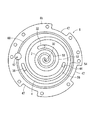
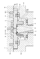
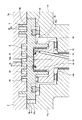
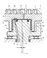
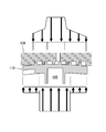
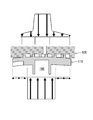
- FIG. 2 is a longitudinal side view of the scroll unit portion of FIG. 1 in the final stage of a working fluid suction process. It is a top view of the eccentric shaft part which saw through the movable scroll of FIG. It is another vertical side view of the scroll unit part of FIG. 1 when expansion
- FIG. 5 is another vertical side view of the scroll unit portion illustrating the operation of the scroll type fluid machine of FIG. 1.
- FIG. 6 is still another longitudinal side view of the scroll unit portion for explaining the operation of the scroll type fluid machine of FIG. 1.
- FIG. 11 is a ph diagram of the refrigeration cycle of FIG. 10. It is a vertical side view of the scroll unit part of the conventional scroll type fluid machine.
- FIG. 1 has shown the vertical side view of the scroll type fluid machine 1 of an Example.
- the scroll type fluid machine 1 according to the embodiment is, for example, a vertically installed single-plate type compressor-integrated expander, and a refrigeration cycle such as a heat pump using carbon dioxide having a high pressure side as a supercritical pressure as a refrigerant (working fluid). Used for RC (shown in FIG. 10).
- a refrigeration cycle such as a heat pump using carbon dioxide having a high pressure side as a supercritical pressure as a refrigerant (working fluid).
- RC used for RC (shown in FIG. 10).
- the scroll fluid machine 1 according to the embodiment is incorporated in an air conditioner, a heat pump type hot water heater, or the like (not shown), and the expansion unit described later performs an expansion operation by the pressure of the refrigerant. 2 and a compression section 4 (lower stage side) which performs a compression operation by the expansion operation of the expansion section 2 (described later) (FIG. 2).
- the scroll fluid machine 1 includes a housing 6.
- a scroll unit 12 mainly composed of a fixed scroll 8 and a movable scroll 10 revolving around the fixed scroll 8, and a main frame (supporting the revolving orbiting motion) Frame) 14 and a crankshaft 16 rotatably supported by a lower bearing portion 14c of the main frame 14 via a bearing member 18.
- the housing 6 includes an outer peripheral portion 14 a of the main frame 14, a cap-shaped top shell 20 that covers the upper portion of the main frame 14, and a cap-shaped bottom shell 22 that covers the lower portion of the main frame 14.
- the housing 6 is assembled by fastening the top shell 20 and the bottom shell 22 together with bolts 25 so as to sandwich the outer peripheral portion 14a via an O-ring 23, and the inside is sealed from the outside.
- a pressure obtained by compressing the refrigerant (carbon dioxide) taken in from the refrigeration cycle RC as the working fluid of the scroll type fluid machine 1 by the compression unit 4 is acting.
- the top shell 20 includes an expansion side suction pipe 24 that sucks the refrigerant taken in from the refrigeration cycle RC into the expansion section 2, and an expansion side discharge pipe 26 that discharges the refrigerant expanded in the expansion section 2 toward the refrigeration cycle RC.
- the compression side discharge pipe 28 which discharges the refrigerant
- the ends of the expansion side suction pipe 24 and the expansion side discharge pipe 26 are opened and communicated with an expansion side suction chamber 30 and an expansion side discharge chamber 32 formed in the substrate 8a of the fixed scroll 8, respectively.
- An end portion of the pipe 28 is opened and communicated with a compression side discharge chamber 34 formed inside the top shell 20.
- the outer peripheral portion 14 a of the main frame 14 is connected to a compression side suction pipe 36 that sucks the refrigerant taken in from the refrigeration cycle RC into the compression section 4, and an end portion of the compression side suction pipe 36 is a substrate of the fixed scroll 8.
- the compression side suction chamber 38 formed in 8a is opened and communicated.
- a lubricating oil chamber 40 is formed inside the bottom shell 22, and lubricating oil for lubricating the scroll unit 12 is stored in the lubricating oil chamber 40.
- an oil feed hole 62 (FIG. 2) penetrating the substrate 8a and the main frame 14 of the fixed scroll 8 is opened, and the lubricating oil in the lubricating oil chamber 40 is compressed through the oil feed hole 62 on the compression side. Oil is supplied to the suction chamber 38.
- An oil supply passage 42 is formed in the crankshaft 16 along the axial direction of the crankshaft 16.
- the lower end of the oil supply passage 42 opens into the lubricating oil chamber 40, and the upper end is the upper end of the crankshaft 16.
- the upper end of the oil supply passage 42 is a back pressure chamber 68 (described later) partitioned by a seal ring 48 as a ring-shaped seal member that is fitted and inserted into the upper surface (end surface in the embodiment) of the eccentric shaft portion 35.
- the opening is made on the outer peripheral portion 68a side (outside of the seal ring 48).
- the seal ring 48 is slidably brought into contact with the back surface 10c, which is the surface opposite to the base surface 10b of the substrate 10a, along with the revolution turning motion of the movable scroll 10.
- the fixed scroll 8 is fixed to the inner side of the outer peripheral portion 14a of the main frame 14, and a compression side discharge hole 44, which will be described later, is slightly in the radial direction of the fixed scroll 8 with respect to the compression side suction chamber 38 of the substrate 8a of the fixed scroll 8. Is formed through.
- An oil separator 45 that separates the lubricating oil in the refrigerant is attached to the opening of the compression side discharge hole 44 with respect to the compression side discharge chamber 34.
- the movable scroll 10 is supported on the pedestal portion 14b of the main frame 14 through a rotation prevention mechanism 46 such as an Oldham ring so as to be capable of revolving without rotating.
- the rotation prevention mechanism 46 is inserted into the pedestal portion 14b, and is slidably connected to the back surface 10c, which is the surface opposite to the base surface 10b of the substrate 10a, along with the revolving turning motion of the movable scroll 10.
- the above-described cylindrical boss 50 into which the eccentric shaft portion 35 is slidably inserted via a bearing member 59 is provided on the back surface 10c of the movable scroll 10.
- the eccentric shaft portion 35 is integrally formed with a balance weight 80 positioned outside the boss 50.
- the scroll unit 12 of the embodiment can form both the compression unit 4 and the expansion unit 2 as a refrigerant working chamber by a set of the fixed scroll 8 and the movable scroll 10 in the compressor-integrated expander.
- the crankshaft 16 supports the movable scroll 10 together with the main frame 14 so as to be capable of revolving motion, and the crankshaft 16 itself is also rotationally driven.
- annular intermediate partition wall (annular wall) 52 and an annular outer partition wall 54 are erected on the base surface 8 b of the fixed scroll 8.
- a spiral outer fixed scroll wrap (wrap) 56 is provided between the outer partition wall 54 and a spiral inner fixed scroll wrap (wrap) 58 on the center side of the intermediate partition wall 52.
- the aforementioned compression side suction chamber 38 is formed at the outer peripheral end of the compression portion 4 slightly inside the outer partition wall 54, and the inner peripheral end of the compression portion 4 slightly outside the intermediate partition wall 52.
- a compression-side discharge hole 44 is formed in the upper part.
- the expansion side discharge chamber 32 described above is formed on the outer peripheral end of the expansion portion 2 slightly inside the intermediate partition wall 52 on the substrate 8a, and the expansion side suction chamber 30 described above is the inner peripheral end of the expansion portion 2. It is formed at the center.
- an annular oil groove 60 is formed on the substrate 8a slightly outside the outer partition wall 54, and is countersunk at a predetermined depth with a diameter larger than the groove width provided on the oil groove 60.
- the oil feed hole 62 described above is formed in the bottom surface of the formed recess.
- a spiral outer movable scroll wrap (wrap) 64 that meshes with the outer fixed scroll wrap 56 and a spiral that meshes with the inner fixed scroll wrap 58.
- the inner movable scroll wrap (wrap) 66 is erected in the direction of the opposite spiral.
- a through hole 61 is formed in the substrate 10 a of the movable scroll 10 on the inner side of the center side portion of the inner movable scroll wrap (wrap) 66.
- the inlet at the upper end (one end) of the through hole 61 opens at the base surface 10 b and communicates with the expansion side suction chamber 30.
- the outlet of the lower end (the other end) of the through-hole 61 is a center portion 68b side (the inside of the seal ring 48) of a back pressure chamber 68 (described later) that is always partitioned by the seal ring 48 during the revolving turning motion of the movable scroll 10. Open at.
- the expansion part 2 is formed inside the intermediate partition wall 52, and the compression part 4 is formed between the intermediate partition wall 52 and the outer partition wall 54.
- the refrigerant sucked from the expansion side suction pipe 24 is taken into the expansion unit 2 through the expansion side suction chamber 30, and the scrolls 8, 10 cooperate with each other.
- it is expanded in an expansion chamber E (FIG. 4, working chamber) formed between the laps 58 and 66.
- the volume of the expansion chamber E is increased while moving toward the outer peripheral side of each scroll 8, 10, and accordingly, the movable scroll 10 is revolved around the axis of the fixed scroll 8.
- the refrigerant used for the revolving orbiting motion of the movable scroll 10 is discharged toward the refrigeration cycle RC outside the housing 6 through the expansion side discharge chamber 26 via the expansion side discharge chamber 32.
- the refrigerant sucked from the compression side suction pipe 36 is taken into the compression unit 4 through the compression side suction chamber 38, and the movable scroll 10 is axially centered on the fixed scroll 8 as the refrigerant expands in the expansion chamber E described above.
- the scrolls 8 and 10 are compressed in a compression chamber P (FIG. 4, working chamber) formed between the laps 56 and 64 by cooperating with each other.
- the volume of the compression chamber P is reduced while moving toward the center of each scroll 8, 10 in accordance with the revolving turning motion of the movable scroll 10.
- the high pressure refrigerant passes through the compression side discharge hole 44 and the compression side discharge chamber 34 and is discharged toward the refrigeration cycle RC outside the housing 6. Is done.
- the refrigerant discharged from the compression side discharge hole 44 to the compression side discharge chamber 34 has the lubricating oil in the refrigerant passing through the oil separator 45.
- the lubricating oil separated from the refrigerant enters the lubricating oil chamber 40 through an oil return path 63 formed between the notch 47 formed on the outer peripheral surface of the substrate 8 a of the fixed scroll 8 and the inner peripheral surface of the main frame 14. Stored.
- the lubricating oil stored in the lubricating oil chamber 40 rises in the oil supply passage 42 by centrifugal force and is discharged from the upper surface of the eccentric shaft portion 35 at the upper end of the crankshaft 16 outside the seal ring 48, and the eccentric shaft portion 35 and the boss 50. After being lubricated, the pressure reaches the back pressure chamber 68 formed between the base portion 14b of the main frame 14 and the back surface 10c of the movable scroll 10.
- the refrigerant sucked into the expansion side suction chamber 30 from the expansion side suction pipe 24 (refrigerant maintained at a high pressure compressed by a high-stage side compressor 70 described later). It is supplied to the inside of the seal ring 48, that is, to the center portion 68 b of the back pressure chamber 68. Therefore, the movable scroll 10 is pressed and urged against the fixed scroll 8 by the high pressure compressed by the high-stage compressor 70 from the center portion 68b of the back pressure chamber 68.
- the scroll unit 12 Due to the back pressure from the back pressure chamber 68, a smooth revolving motion of the movable scroll 10 with respect to the fixed scroll 8 becomes possible.
- the scroll unit 12 is driven by the expansion energy of the refrigerant in the expansion unit 2, and the refrigerant is compressed in the compression unit 4 by the driving force of the scroll unit 12.
- FIGS. 4 and 6 are vertical side views of the scroll unit 12 enlarged to explain the structure of the eccentric shaft portion 35
- FIG. 8 is an enlarged vertical side view of the eccentric shaft portion 35.
- FIG. 5 and 7 show a plan view of the eccentric shaft portion 35 as seen through the movable scroll 10 (the through hole 61 is indicated by a solid line).
- FIG. 9 is a plan sectional view of the center portion of the fixed scroll 8 and the movable scroll 10 (viewed from the eccentric shaft portion 35 side (lower side)).
- the inlet at the upper end of the through-hole 61 is opened at the base surface 10 b, and this inlet is connected to the inner fixed scroll wrap (wrap) of the fixed scroll 8 according to the revolution turning motion of the movable scroll 10. It is arranged at a position opened and closed by the front end of 58. 4 shows a state where the wrap 58 is opened, and FIG. 6 shows a closed state.
- the seal ring 48 revolves around the movable scroll 10, the position of the through hole 61 with respect to the seal ring 48 also changes during the revolving swivel movement of the movable scroll 10.
- the outlet at the lower end is always arranged so as to correspond to the central portion 68 b of the back pressure chamber 68 partitioned by the seal ring 48.
- FIG. 5 shows the groove 78 through the movable scroll 10, but the end of the inner side (the axial center side of the eccentric shaft portion 35) of the groove 78 is caused by the revolution rotation of the seal ring 48 as described above. It changes into the state (FIGS. 4 and 5) closed by the state (FIGS. 4 and 5) and the state where the seal ring 48 straddles the groove 78 (FIGS. 6 and 7).
- the positional relationship between the through hole 61 and the groove 78 extends in the eccentric direction of the seal ring 48 (center X1) with respect to the eccentric shaft portion 35 (axis X2). Further, in the state where the inlet of the through hole 61 is opened by the tip of the inner fixed scroll wrap (wrap) 58 of the fixed scroll 8 as shown in FIG. 7 is closed by the seal ring 48, the central portion 68b of the back pressure chamber 68 and the outer peripheral portion 68a are not in communication, and the inlet of the through hole 61 is closed by the tip of the wrap 58. As described above, the seal ring 47 straddles the groove 78, and the center part 68b and the outer peripheral part 68a of the back pressure chamber 68 are communicated with each other by the pressure relief path 81.
- X3 is the turning center of the movable scroll 10, and the axis of the crankshaft 16
- the center and the inner fixed scroll wrap (wrap) 58 of the fixed scroll 8 are located at the center of the spiral base circle.
- X4 is the center of the spiral base circle of the inner movable scroll wrap (wrap) 66 of the movable scroll 10, and is offset from the turning center X3 in the eccentric direction of the eccentric shaft portion 35.
- the distance between the turning center X3 and the center circle center X4 of the spiral of the wrap 66 of the movable scroll 10 is the turning radius R1 of the movable scroll 10.
- the center position X5 of the center portion 68b of the back pressure chamber 68 partitioned by the seal ring 48 (that is, the area gravity center position of the center portion 68) is set to the turning center X3 of the movable scroll 10 as shown in FIG. Therefore, the turning radius R1 of the movable scroll 10 is shifted by 1 ⁇ 2 in the eccentric direction of the eccentric shaft portion 35.
- the area gravity center position G1 of the expansion chamber (the central chamber E1, the working chamber E2, the working chamber E3) of the expansion section 2 and the area gravity center position X5 of the central portion 68b of the back pressure chamber 68 coincide with each other. Thereby, generation
- FIG. 10 shows a refrigerant circuit diagram of a refrigeration cycle RC (Example) using the scroll type fluid machine 1 of the present invention.
- the compression unit 4 driven by the power recovered by the expansion unit 2 of the scroll type fluid machine 1 constitutes a low-stage compressor (low-stage compression unit) in the refrigeration cycle RC.
- the above-described compression-side discharge pipe 28 of the compression unit 4 is connected to a high-stage side compression unit 70 a that is driven by an electric motor 70 b of a high-stage side compressor 70 that is located downstream of the compression unit 4.
- a gas cooler 71 for cooling the refrigerant is connected to the subsequent stage of the compression unit 70a. Between the outlet of the gas cooler 71 and the inlet of the evaporator 73, the expansion unit 2 and the expansion valve 72 of the scroll type fluid machine 1 are connected in parallel. It is connected. The refrigerant from the gas cooler 71 is taken into the expansion side suction chamber 30 of the expansion unit 2 from the expansion side suction pipe 24 described above. Further, the refrigerant is sent from the expansion section 2 of the scroll type fluid machine 1 to the evaporator 73 via the expansion side discharge pipe 26. The refrigerant discharged from the evaporator 73 is sucked into the compression unit 4 of the scroll fluid machine 1 from the compression side suction pipe 36.
- the expansion valve 72 is provided for adjusting the flow rate of the refrigerant passing through the expansion portion 2 of the scroll type fluid machine 1 and ensuring the differential pressure at the time of startup.
- the movable scroll 10 revolves and the power is recovered.
- the revolving orbiting motion of the movable scroll 10 causes the compression unit 4 to operate as a low-stage compressor.
- the refrigerant expanded in the expansion unit 2 is heated by the evaporator 73 (or the object is thereby cooled), and is again sucked into the compression unit 4 of the scroll type fluid machine 1 through the compression side suction pipe 36.
- FIG. 14 shows a ph diagram of the refrigeration cycle RC.
- the refrigerant cooled from the point D to the point C by exchanging heat with the gas cooler 71 expands isentropically in the expansion part 2 of the scroll type fluid machine 1, thereby causing a liquidus line. It enters the wet steam region beyond LL and becomes point B.
- the heat exchanged by the evaporator 73 and the refrigerant heated from the point B to the point A is compressed from the point A to the point A1 by the compression unit 4 of the scroll type fluid machine 1 and then the high-stage compressor.
- the compression is performed from point A1 to point D by the compression unit 70a.
- the compression unit 70a of the high-stage side compressor 70 bears a part of the compression process of the refrigeration cycle RC (high-stage side), and the compression unit 4 of the scroll fluid machine 1 has the rest of the compression process (low-stage side). Side).
- the compression power for the enthalpy difference hA1 ⁇ hA in the compression unit 4 is covered by the recovery power in the expansion unit 2.
- the movable scroll 10 is moved against the fixed scroll 8 by the discharge pressure of the compression portion 4 from the outer peripheral portion 68a of the back pressure chamber 68 and by the high pressure compressed by the high-stage compressor 70 from the central portion 68b. And pressed.
- the discharge pressure of the high-stage compressor 70 is applied to the central portion of the base surface 10b of the movable scroll 10, and the pressure decreases and expands toward the outside.
- This pressure is indicated by an arrow in FIG. 11 (in this figure, the length of the arrow similarly indicates the magnitude of the pressure).
- the refrigerant maintained at the discharge pressure (high pressure) of the high-stage compressor 70 is supplied to the central portion 68b, and the discharge pressure (intermediate pressure) of the compression section 4 is supplied to the outer peripheral portion 68a.
- the refrigerant kept at is supplied.
- a force (the force applied to the base surface 10 b shown in the upper side of FIG. 11) that pulls the movable scroll 10 away from the fixed scroll 8, and the movable scroll 10 is pressed against the fixed scroll 8.
- the force (back pressure shown in the lower side of FIG. 11) is substantially the same in almost the entire area of the movable scroll 10, and the problem that the substrate 10a of the movable scroll 10 bends is solved while preventing a decrease in efficiency. Will be able to.
- the back pressure chamber 68 formed on the back side of the movable scroll 01 is divided into a center portion 68b and an outer peripheral portion 68a by the seal ring 48, and a high-stage compressor is provided in the center portion 68b of the back pressure chamber 68.
- the refrigerant maintained at the high pressure compressed at 70 is supplied, and the refrigerant maintained at the discharge pressure of the compression unit 4 on the lower stage side is supplied to the outer peripheral portion 68a of the back pressure chamber 68.
- the seal ring 48 is provided on the upper surface (end surface) of the eccentric shaft portion 35 and is slidably contacted with the back surface of the movable scroll 10, and the high pressure is maintained by the through hole 61 formed in the movable scroll 10. Since the leaning refrigerant is supplied to the central portion 68b of the back pressure chamber 68, the structure for supplying high pressure to the back pressure chamber 68 can be remarkably simplified.
- FIG. 9 shows a position where the movable scroll 10 is turned to an angle of about 150 ° crank angle in one expansion process.
- the expansion chamber E at the center (the central chamber E1 in FIG. 9) is sucked into the expansion side suction chamber 30 from the expansion side suction pipe 24.
- the refrigerant that has been compressed by the high-stage compressor 70 and maintained at a high pressure flows in.
- the volume of the central chamber E1 increases, and the outer expansion chamber E (the working chambers E2 and E3 in FIG. 9) is separated at a crank angle of about 0 °.
- the volumes of the working chambers E2 and E3 are further expanded, so that the refrigerant in the working chambers E2 and E3 expands and the pressure rapidly decreases.
- the high pressure portion in FIGS. 17 and 18 described above is the pressure in the central chamber E1, and the pressure sharply decreases from around the crank angle of 0 ° is the pressure in the working chambers E2 and E3 after being separated from the central chamber. Show.
- the wrap 58 opens the through-hole 61 at a stage before the working chambers E2 and E3 are separated from the central chamber E1 in a certain expansion process. Then, the working chambers E2 and E3 are separated from the central chamber E1 in the vicinity of the crank angle of 0 °, and the refrigerant inside them starts to expand and exceeds the liquidus line LL of FIG. Then, the through-hole 61 is arranged so that the lap 58 closes the inlet of the through-hole 61 at around 24 ° and then reopens at around the crank angle of 230 °.
- L2 in FIG. 21 indicates a change in the axial force applied to the movable scroll 10 with respect to the turning angle (crank angle) of the movable scroll 10, and this means that the center of the movable scroll 10 is separated from the fixed scroll 8. It is a pulling force to try.
- This pulling-off force rapidly decreases from the maximum crank angle of 0 ° to 11 °, then gradually increases, and shows a maximum change at 360 ° (next 0 °). Since this is the total force generated from the pressure of the refrigerant in the central chamber E1 and each of the working chambers E2, E3, it changes in this way.
- the lap 58 opens the inlet of the through hole 61 until the crank angle is close to 24 °, and the pressure relief path 81 does not communicate with the central portion 68b of the back pressure chamber 68 and the outer peripheral portion 68a. Therefore, high-pressure refrigerant flows into the center portion 68b from the through hole 61, and the pressing force that presses the center portion of the movable scroll 10 against the fixed scroll 8 becomes high pressure. Thereafter, after the refrigerant exceeds the liquidus line LL and becomes a wet steam region, the inlet of the through hole 61 is closed with a wrap 58 and the seal ring 48 straddles the groove 78, so that the pressure relief path 81 is formed in the back pressure chamber 68. The central portion 68b and the outer peripheral portion 68a communicate with each other.
- the inlet of the through hole 61 is opened and high pressure is supplied to the central portion 68b of the back pressure chamber 68, and the central portion 68b and the outer peripheral portion 68a.
- the inlet of the through-hole 61 is closed by the inner fixed scroll wrap 58 of the fixed scroll 8 to increase the pressure. Can be stopped and the central portion 68b and the outer peripheral portion 68a can be communicated to reduce the back pressure to the discharge pressure of the compression portion 4 in the entire movable scroll 10.
- the inlet of the through hole 61 is closed after the refrigerant in the expansion chamber E reaches the wet vapor region beyond the liquidus line LL, so that the pulling force L2 toward the center of the movable scroll 10 is ensured.
- the back pressure at the center can be lowered, and the application of high pressure to the center 68b of the back pressure chamber 68 can be stopped at an appropriate timing.
- the seal ring 48 straddles the groove 78, so that the pressure relief path 81 communicates the center portion 68 b and the outer peripheral portion 68 a of the back pressure chamber 68.
- the central portion 68b and the outer peripheral portion 68a are communicated with each other in accordance with the stop of the application of the high pressure to the central portion 68b.
- the discharge pressure is lowered.
- the pressure in the back pressure chamber 68 is made uniform at the center 68b and the outer periphery 68a to ensure that excessive pressing force is generated. Can be prevented.
- a pressure relief path 81 is formed in the groove 78 formed on the back surface 10 c of the movable scroll 10, and the center of the back pressure chamber 68 is in a state where the seal ring 48 closes the inner end of the groove 78.
- the part 68b and the outer peripheral part 68a are brought into a non-communication state, and the seal ring 48 straddles the groove 78 to open both end parts of the groove 78. Since it is configured to communicate, the structure can be significantly simplified.
- the present invention is applied by taking a so-called single-plate compressor-integrated scroll expander as an example of a scroll type fluid machine, but the invention of claim 1 is not limited thereto, and the expansion portion and the compression portion are not limited thereto.
- the present invention is also effective for a scroll type fluid machine connected by a drive shaft.
Landscapes
- Engineering & Computer Science (AREA)
- Mechanical Engineering (AREA)
- General Engineering & Computer Science (AREA)
- Physics & Mathematics (AREA)
- Geometry (AREA)
- Rotary Pumps (AREA)
- Applications Or Details Of Rotary Compressors (AREA)
Abstract
【課題】膨張部の入口における作動流体の温度が変化した場合にも、可動スクロールに適切な背圧を印加することが可能なスクロール型流体機械を提供する。 【解決手段】固定スクロール8と可動スクロール10の各ラップ58、66間に形成された膨張室Eで冷媒を膨張させ、可動スクロールを公転旋回運動させる膨張部2と、膨張部で回収した動力で冷媒を圧縮する低段側の圧縮部4を備え、高段側の圧縮機で圧縮された高圧の冷媒を膨張部の中心部より吸入する。可動スクロール背面の背圧室68を中心部68bと外周部68aに仕切るシールリング48を備える。背圧室の中心部に高圧に保たれた冷媒を供給し、背圧室の外周部には圧縮部の吐出圧力に保たれた冷媒を供給する。
Description
本発明は、固定及び可動スクロールから成る膨張部を備えたスクロール型流体機械に関するものである。
この種のスクロール型流体機械としては、基面にラップを設けた可動スクロールと、基面にこの可動スクロールのラップと噛合うラップを設けた固定スクロールとから構成されるスクロールユニットを備え、このスクロールユニットの作動室を仕切り壁により圧縮室と膨張室とに仕切って、圧縮部と膨張部とを形成した単板式の圧縮機一体型膨張機が知られている(例えば、特許文献1参照)。
図15は上記特許文献1のスクロールユニット100部分を拡大して示している。固定スクロール108の基面には、環状の中間仕切壁(環状壁)152と、環状の外側仕切壁154とが立設され、中間仕切壁152と外側仕切壁154との間には渦巻き状の外側固定スクロールラップ(ラップ)156、中間仕切壁52よりも中心側には渦巻状の内側固定スクロールラップ(ラップ)158がそれぞれ立設されている。
固定スクロール108の基板108Aには、圧縮側吸入室138が外側仕切壁154の内側の圧縮部104の外周端に形成され、中間仕切壁152の外側の圧縮部104の内周端に圧縮側吐出孔144が形成されている。また、基板108Aには、膨張側吐出室132が中間仕切壁152の内側の膨張部102の外周端に形成され、膨張側吸入室130が膨張部102の内周端である中心部に形成されている。
一方、可動スクロール110の基面には、外側固定スクロールラップ156に噛合う渦巻き状の外側可動スクロールラップ(ラップ)164と、内側固定スクロールラップ158に噛合う渦巻き状の内側可動スクロールラップ(ラップ)166とが相反する渦巻の方向で立設されている。このスクロールユニット100では、中間仕切壁152よりも内側に膨張部102が形成され、中間仕切壁152と外側仕切壁154との間に圧縮部104が形成される。
そして、膨張側吸入室130から高段側の圧縮機(図示せず)で圧縮された高圧に保たれた作動流体が吸入され、膨張部102のラップ158と166間に形成された膨張室で膨張することで可動スクロール110が公転旋回運動され、動力が回収される。この動力により、圧縮部104のラップ156と164間に形成された圧縮室で作動流体を圧縮する。この圧縮部104は低段側となり、圧縮部104で圧縮された作動流体が高段側の圧縮機に吸い込まれることになる。
また、可動スクロール110の背面側には背圧室168が構成されている。この背圧室168には、圧縮部104の吐出圧力に保たれた作動流体が供給され、その圧力によって可動スクロール110が固定スクロール108に対して押圧付勢されるものであった。
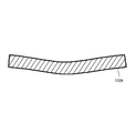
このように従来では、可動スクロール110の背圧室168(膨張部102と圧縮部104に対応する全体)が圧縮部104の吐出圧力とされていた。一方、可動スクロール110の基面の中心部には、高段側の圧縮機の吐出圧力が加わる。この圧力の大小関係を図15に矢印で示す。この図において、矢印の長さは圧力の大きさを示している(以下、同じ)。このように、可動スクロール110に加わる背圧室168からの圧力は全体に比較的低く、基面に加わる圧力は中心部が極めて高い状況となるため、作動流体の漏れが発生し易い可動スクロール110の基板110Aの中央部が、図16のように撓んでしまう。
これを解消するために背圧室168全体に高段側の圧縮機の吐出圧力を供給すると、今度は固定スクロール108と可動スクロール110の基面間の摺動抵抗が増大し、効率が著しく低下してしまう問題があった。
これを防止するために、前記特許文献2の如く背圧室168をシール部材で中心部と外周部とに仕切り、中心部に膨張部102の吸込圧力(高圧)を供給し、外周部には膨張部102の吐出圧力を供給する構造が提案されている。
しかしながら、膨張部102における膨張過程での圧力変化の特性は、膨張部102に吸い込まれる作動流体の温度によって大きく異なる。図17は膨張部102の入口における作動流体の温度が+40℃の場合の膨張過程での圧力変化を示し、図18は膨張部102の入口における作動流体の温度が+20℃の場合の膨張過程での圧力変化を示す。尚、各図において縦軸は圧力、横軸は可動スクロール110が公転旋回するクランク角を示す。また、図19は図17の場合の可動スクロール110の基面に加わる圧力と背圧との大小関係を示し、図20は図18の場合の可動スクロール110の基面に加わる圧力と背圧との大小関係を示す。
これらの図から明らかな如く、膨張部102の入口における作動流体の温度が高い場合(図17、図19)、膨張過程の圧力の低下が緩慢となるため、可動スクロール110を固定スクロール108から引き離そうとする力は大きくなる。但し、膨張による動力も大きくなるため、圧縮部104における仕事量は増大する。
一方、膨張部102の入口における作動流体の温度が低い場合(図18、図20)、膨張過程の圧力は膨張初期に急激に低下するため、可動スクロール110を固定スクロール108から引き離そうとする力は小さくなる。そして、膨張による動力も小さくなるため、圧縮部104における仕事量も減少する。
このように、膨張部102における膨張過程での圧力変化の特性が、膨張部の入口における作動流体の温度によって大きく異なるため、特許文献2の如くシール部材により背圧室168を中心部と外周部とに仕切り、中心部に膨張部102の吸込圧力(高圧)を供給し、外周部に膨張部102の吐出圧力を供給するようにした場合、或る作動流体の温度では最適であっても、温度が上昇した場合には背圧が過剰となって摺動損が増大し、逆に低下した場合には背圧が不足して漏れが生じ、何れの場合にも効率の低下を招く。そのため、膨張部102の入口の作動流体温度に対応する調整手段を別途設けなければならなくなる問題があった。
本発明は、係る従来の技術的課題を解決するために成されたものであり、膨張部の入口における作動流体の温度が変化した場合にも、可動スクロールに適切な背圧を印加することが可能なスクロール型流体機械を提供することを目的とする。
上記課題を解決するために、本発明のスクロール型流体機械は、各基板の各基面にそれぞれ渦巻き状のラップが対向して形成された固定スクロール及び可動スクロールから構成され、両スクロールの各ラップ間に形成された膨張室で作動流体を膨張させることにより、可動スクロールを公転旋回運動させて動力を回収する膨張部と、この膨張部で回収された動力で作動流体を圧縮する低段側の圧縮部とを備え、高段側の圧縮機で圧縮された高圧の作動流体を膨張部の中心部より吸入するものであって、可動スクロールの背面側に形成された背圧室と、この背圧室を中心部と外周部とに仕切るシール部材とを備え、背圧室の中心部に高圧に保たれた作動流体を供給し、背圧室の外周部には圧縮部の吐出圧力に保たれた作動流体を供給することを特徴とする。
請求項2の発明のスクロール型流体機械は、上記発明において圧縮部は、膨張部の外側における両スクロールの各ラップ間に形成された圧縮室で作動流体を圧縮することを特徴とする。
請求項3の発明のスクロール型流体機械は、上記各発明において可動スクロールの背面側より突出するボスと、クランク軸と、このクランク軸の端部に形成され、ボスに摺動且つ回転可能に嵌挿された偏心軸部とを備え、シール部材を偏心軸部の端面に設けて可動スクロールの背面に摺動可能に当接させ、この可動スクロールに形成した貫通孔により高圧に保たれた作動流体を背圧室の中心部に供給することを特徴とする。
請求項4の発明のスクロール型流体機械は、上記発明において可動スクロールの旋回運動に応じて、固定スクロールのラップにより貫通孔の入口が開閉されることを特徴とする。
請求項5の発明のスクロール型流体機械は、上記発明において貫通孔の入口は、膨張室内の作動流体が液相線を越えて湿り蒸気領域となった後に閉じられるよう構成したことを特徴とする。
請求項6の発明のスクロール型流体機械は、請求項4又は請求項5の発明において貫通孔の入口が閉じられたとき、背圧室の中心部と外周部とを連通する圧力逃がし路を備えたことを特徴とする。
請求項7の発明のスクロール型流体機械は、上記発明において可動スクロールの背面に形成された溝により圧力逃がし路を構成し、シール部材が溝の端部を塞いでいる状態では背圧室の中心部と外周部は非連通状態となり、シール部材が溝を跨ぐことで溝の両端部が開放され、背圧室の中心部と外周部が連通されるよう構成したことを特徴とする。
請求項8の発明のスクロール型流体機械は、請求項3乃至請求項7の発明においてシール部材はリング状を成し、偏心軸部の端面に偏心配置されていることを特徴とする。
請求項9の発明のスクロール型流体機械は、請求項3乃至請求項8の発明においてシール部材で仕切られる背圧室の中心部を、可動スクロールの旋回中心から、偏心軸部の偏心方向に、可動スクロールの旋回半径の1/2ずらしたことを特徴とする。
請求項10の発明のスクロール型流体機械は、上記各発明において作動流体としては二酸化炭素を使用したことを特徴とする。
前述した如く、各基板の各基面にそれぞれ渦巻き状のラップが対向して形成された固定スクロール及び可動スクロールから構成され、両スクロールの各ラップ間に形成された膨張室で作動流体を膨張させることにより、可動スクロールを公転旋回運動させて動力を回収する膨張部と、この膨張部で回収された動力で作動流体を圧縮する低段側の圧縮部とを備え、高段側の圧縮機で圧縮された高圧の作動流体を膨張部の中心部より吸入するスクロール型流体機械においては、膨張部の入口における作動流体の温度が高い場合、膨張過程の圧力の低下が緩慢となるため、可動スクロールを固定スクロールから引き離そうとする力は大きくなるが、膨張による動力も大きくなるため、圧縮部における仕事量も増大する。逆に、膨張部の入口における作動流体の温度が低い場合は、膨張過程の圧力は膨張初期に急激に低下するため、可動スクロールを固定スクロールから引き離そうとする力は小さくなるが、膨張による動力も小さくなるため、圧縮部における仕事量も減少する。
そこで本発明では、可動スクロールの背面側に形成された背圧室を、シール部材により中心部と外周部とに仕切り、背圧室の中心部に高段側の圧縮機で圧縮された高圧に保たれた作動流体を供給し、背圧室の外周部には低段側の圧縮部の吐出圧力に保たれた作動流体を供給するようにしたので、膨張部の入口における作動流体の温度が高い場合は圧縮部の仕事量が増大し、その吐出圧力も高くなって背圧室の外周部に供給される圧力は上昇し、膨張部の入口における作動流体の温度が低い場合は圧縮部の仕事量が減少し、その吐出圧力も低くなって背圧室の外周部に供給される圧力も低下する。
即ち、膨張部の入口における作動流体の温度が高く、可動スクロールを固定スクロールから引き離そうとする力が大きくなるときは、背圧室の外周部に供給される圧力が上昇し、膨張部の入口における作動流体の温度が低く、可動スクロールを固定スクロールから引き離そうとする力が小さくなるときは、背圧室の外周部に供給される圧力も低下するようになり、自動的に両者をバランスさせることが可能となる。これにより、別途複雑な調整手段を設けることなく、可動スクロールに背圧を適切に印加して高効率な運転を実現することが可能となる。
これは請求項2のような膨張部と圧縮部とが一体化された単板式のスクロール型流体機械において、請求項10の如き二酸化炭素を作動流体として使用する場合に特に有効である。
この場合、請求項3の発明の如く、可動スクロールの背面側より突出するボスと、クランク軸と、このクランク軸の端部に形成され、ボスに摺動且つ回転可能に嵌挿された偏心軸部とを備え、シール部材を偏心軸部の端面に設けて可動スクロールの背面に摺動可能に当接させ、この可動スクロールに形成した貫通孔により高圧に保たれた作動流体を背圧室の中心部に供給することにより、背圧室に高圧を供給する構造を著しく簡素化することが可能となる。
また、請求項4の発明の如く、可動スクロールの旋回運動に応じて、固定スクロールのラップにより貫通孔の入口が開閉されるようにすることで、可動スクロールの中心部を固定スクロールから引き離そうとする引き離し力が大きくなる状態では、貫通孔の入口を開放して背圧室の中心部に高圧を供給し、可動スクロールの中心部を引き離そうとする力に対抗すると共に、引き離し力が小さくなる状態では、貫通孔の入口を固定スクロールのラップにより閉じて、高圧の供給を停止することが可能となる。
これにより、中心部への過剰な背圧印加による固定スクロールへの可動スクロールの過剰な押し付け力の発生を回避し、運転効率の低下を防止することが可能となる。
この場合、請求項5の発明の如く貫通孔の入口を、膨張室内の作動流体が液相線を越えて湿り蒸気領域となった後に閉じるようにすることにより、確実に可動スクロールの中心部への引き離し力が小さくなった後に、中心部の背圧を下げることができるようになり、的確なタイミングで背圧室の中心部への高圧印加を停止することが可能となる。
また、請求項6の発明の如く貫通孔の入口が閉じられたとき、背圧室の中心部と外周部とを連通する圧力逃がし路を設ければ、背圧室の中心部への高圧印加を停止したことに合わせて中心部と外周部を連通することができるようになる。これにより、中心部の引き離し力が急激に低下するのに合わせて、背圧室の圧力を中心部と外周部で均一化し、過剰な押し付け力の発生を確実に防止することができるようになる。
この場合も、請求項7の発明の如く可動スクロールの背面に形成された溝により圧力逃がし路を構成し、シール部材が溝の端部を塞いでいる状態では背圧室の中心部と外周部は非連通状態となり、シール部材が溝を跨ぐことで溝の両端部が開放され、背圧室の中心部と外周部が連通されるよう構成することで、構造の著しい簡素化を図ることが可能となる。
また、請求項8の発明の如くシール部材をリング状とした場合に、偏心軸部の端面に偏心配置すれば、偏心軸部の回転に伴ってシール部材が可動スクロールの同じリング状の位置に当接することがなくなり、可動スクロールがシール部材によって摩耗する度合いを低減することができるようになる。
更に、請求項9の発明の如くシール部材で仕切られる背圧室の中心部を、可動スクロールの旋回中心から、偏心軸部の偏心方向に、可動スクロールの旋回半径の1/2ずらすことにより、膨張部の膨張室の面積重心位置と、背圧室の中心部の面積重心位置とを合致させることができるようになる。これにより、可動スクロールを転覆させようとするモーメントの発生を効果的に防止することができるようになるものである。
以下、本発明の実施の形態について、詳細に説明する。
(1)スクロール型流体機械1の構造
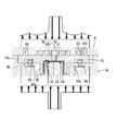
図1は、実施例のスクロール型流体機械1の縦断側面図を示している。実施例のスクロール型流体機械1は、例えば、縦置き型単板式の圧縮機一体型膨張機であり、高圧側が超臨界圧力となる二酸化炭素を冷媒(作動流体)として使用したヒートポンプ等の冷凍サイクルRCに用いられる(図10に示す)。この冷凍サイクルRCの構成については後に詳述するが、図示しない空気調和機やヒートポンプ式給湯機等に組み込まれ、実施例のスクロール型流体機械1は冷媒の圧力によって膨張動作を行う後述する膨張部2と、この膨張部2の膨張動作によって圧縮動作を行う後述する圧縮部4(低段側)とを備えている(図2)。
図1は、実施例のスクロール型流体機械1の縦断側面図を示している。実施例のスクロール型流体機械1は、例えば、縦置き型単板式の圧縮機一体型膨張機であり、高圧側が超臨界圧力となる二酸化炭素を冷媒(作動流体)として使用したヒートポンプ等の冷凍サイクルRCに用いられる(図10に示す)。この冷凍サイクルRCの構成については後に詳述するが、図示しない空気調和機やヒートポンプ式給湯機等に組み込まれ、実施例のスクロール型流体機械1は冷媒の圧力によって膨張動作を行う後述する膨張部2と、この膨張部2の膨張動作によって圧縮動作を行う後述する圧縮部4(低段側)とを備えている(図2)。
スクロール型流体機械1はハウジング6を備えている。このハウジング6内には、主として固定スクロール8とこの固定スクロール8に対し公転旋回運動される可動スクロール10とから構成されるスクロールユニット12と、可動スクロール10を公転旋回運動可能に支持するメインフレーム(フレーム)14と、このメインフレーム14の下部軸受部14cに軸受部材18を介して回転可能に軸支されたクランク軸16とが配設されている。
ハウジング6は、メインフレーム14の外周部14aと、メインフレーム14の上部を覆うキャップ状のトップシェル20と、メインフレーム14の下部を覆うキャップ状のボトムシェル22とから構成されている。ハウジング6は、トップシェル20とボトムシェル22を、Oリング23を介し、外周部14aを挟み込むようにしてボルト25で互いに締結することにより組み立てられ、外部から内部が密閉されている。密閉されたハウジング6内には、スクロール型流体機械1の作動流体として冷凍サイクルRCから取り込んだ冷媒(二酸化炭素)を圧縮部4にて圧縮した圧力が作用している。
トップシェル20には、冷凍サイクルRCから取り込んだ冷媒を膨張部2に吸入する膨張側吸入管24と、膨張部2にて膨張された冷媒を冷凍サイクルRCに向けて吐出する膨張側吐出管26と、圧縮部4にて圧縮された冷媒を冷凍サイクルRCに向けて吐出する圧縮側吐出管28が接続されている。膨張側吸入管24と膨張側吐出管26の端部は、固定スクロール8の基板8a内に形成された膨張側吸入室30と膨張側吐出室32とにそれぞれ開口して連通され、圧縮側吐出管28の端部は、トップシェル20の内側に形成された圧縮側吐出室34に開口して連通されている。
また、メインフレーム14の外周部14aには、冷凍サイクルRCから取り込んだ冷媒を圧縮部4に吸入する圧縮側吸入管36が接続され、圧縮側吸入管36の端部は、固定スクロール8の基板8a内に形成された圧縮側吸入室38に開口され、連通されている。
一方、ボトムシェル22の内側には潤滑油室40が形成され、この潤滑油室40にはスクロールユニット12を潤滑するための潤滑油が貯留される。圧縮側吸入室38には、固定スクロール8の基板8a及びメインフレーム14を貫通する送油孔62(図2)が開口され、送油孔62を介して潤滑油室40の潤滑油が圧縮側吸入室38に送油される。
また、クランク軸16内には、クランク軸16の軸方向に沿って給油路42が穿設されており、この給油路42の下端は潤滑油室40に開口し、上端はクランク軸16の上端(実施例における端部)の偏心軸部35の上面(実施例における端面)にて、可動スクロール10の後述するボス50内の空間に開口している。但し、この給油路42の上端は、偏心軸部35の上面(実施例における端面)に嵌挿して設けられたリング状のシール部材としてのシールリング48により仕切られた後述する背圧室68の外周部68a側(シールリング48の外側)にて開口しているものとする。このシールリング48は可動スクロール10の公転旋回運動に伴い、基板10aの基面10bとは反対側の面である背面10cに摺動可能に当接する。
固定スクロール8はメインフレーム14の外周部14aの内側に固定され、固定スクロール8の基板8aの圧縮側吸入室38よりも固定スクロール8の径方向で若干中心側には後述する圧縮側吐出孔44が貫通して形成されている。圧縮側吐出孔44の圧縮側吐出室34に対する開口部には、冷媒中の潤滑油を分離するオイルセパレータ45が装着されている。
可動スクロール10は、メインフレーム14の台座部14bにオルダムリング等の自転阻止機構46を介して自転することなく公転旋回運動可能に支持されている。この自転阻止機構46は台座部14bに嵌挿され、可動スクロール10の公転旋回運動に伴い基板10aの基面10bとは反対側の面である背面10cに摺動可能に通接される。更に、可動スクロール10の背面10cには、偏心軸部35が軸受部材59を介して摺動且つ回動可能に嵌挿される円筒状の前述したボス50が突設されている。尚、偏心軸部35にはボス50の外側に位置するバランスウエイト80が一体に形成されている。
ここで、実施形態のスクロールユニット12は、圧縮機一体型膨張機において、一組の固定スクロール8及び可動スクロール10によって冷媒の作動室としての圧縮部4と膨張部2との両方を形成可能な、いわゆる単板式スクロールユニットであり、クランク軸16は、メインフレーム14と共に可動スクロール10を公転旋回運動可能に支持し、このクランク軸16自体も回転駆動される。
詳しくは、図2に示されるように、固定スクロール8の基面8bには、環状の中間仕切り壁(環状壁)52と、環状の外側仕切り壁54とが立設され、中間仕切り壁52と外側仕切り壁54との間には渦巻状の外側固定スクロールラップ(ラップ)56、中間仕切り壁52よりも中心側には渦巻状の内側固定スクロールラップ(ラップ)58がそれぞれ立設されている。
固定スクロール8の基板8aには、前述した圧縮側吸入室38が外側仕切り壁54の若干内側の圧縮部4の外周端に形成され、中間仕切り壁52の若干外側の圧縮部4の内周端に圧縮側吐出孔44が形成されている。また、基板8aには、前述した膨張側吐出室32が中間仕切り壁52の若干内側の膨張部2の外周端に形成され、前述した膨張側吸入室30が膨張部2の内周端である中心部に形成されている。更に、基板8aには、外側仕切り壁54の若干外側に環状の油溝60が形成され、油溝60上に設けられた溝幅よりも大きい直径で所定の深さで座ぐり加工を施して形成した凹部の底面に前述した送油孔62が形成されている。
一方、図3に示されるように、可動スクロール10の基面10bには、外側固定スクロールラップ56に噛合う渦巻状の外側可動スクロールラップ(ラップ)64と、内側固定スクロールラップ58に噛合う渦巻状の内側可動スクロールラップ(ラップ)66とが相反する渦巻の方向で立設されている。また、可動スクロール10の基板10aには、内側可動スクロールラップ(ラップ)66の中心側の部分の内側には貫通孔61が形成されている。この貫通孔61の上端(一端)の入口は基面10bにて開口し、膨張側吸入室30に連通する。また、貫通孔61の下端(他端)の出口は可動スクロール10の公転旋回運動中、常に前記シールリング48により仕切られた後述する背圧室68の中心部68b側(シールリング48の内側)にて開口する。
上述したスクロールユニット12によれば、中間仕切り壁52よりも内側に膨張部2が形成され、中間仕切り壁52と外側仕切り壁54との間に圧縮部4が形成される。詳しくは、図1中にて実線矢印で示されるように、膨張側吸入管24から吸入された冷媒は、膨張側吸入室30を経て膨張部2に取り込まれ、各スクロール8、10が互いに協働することによって各ラップ58、66間に形成された膨張室E(図4。作動室)にて膨張される。膨張室Eは、各スクロール8、10の外周側に向けて移動しながらその容積が増大され、これに伴い可動スクロール10が固定スクロール8の軸心周りに公転旋回運動される。可動スクロール10の公転旋回運動に供した冷媒は、膨張側吐出室32を経て膨張側吐出管26を介しハウジング6外の冷凍サイクルRCに向けて吐出される。
一方、圧縮側吸入管36から吸入された冷媒は、圧縮側吸入室38を経て圧縮部4に取り込まれ、上述した膨張室Eでの冷媒の膨張に伴い可動スクロール10が固定スクロール8の軸心周りに公転旋回運動することにより、各スクロール8、10が互いに協働することによって各ラップ56、64間に形成された圧縮室P(図4。作動室)にて圧縮される。圧縮室Pは、可動スクロール10の公転旋回運動に伴い各スクロール8、10の中心に向けて移動しながらその容積が減少される。そして、圧縮室Pの容積の減少に伴い、高圧にされた冷媒は圧縮側吐出孔44、圧縮側吐出室34を経て圧縮側吐出管28を介し、ハウジング6外の冷凍サイクルRCに向けて吐出される。
更に、この過程において図1中にて点線矢印で示されるように、圧縮側吐出孔44から圧縮側吐出室34に吐出される冷媒は、オイルセパレータ45を通過する際に冷媒中の潤滑油が分離される。冷媒から分離された潤滑油は固定スクロール8の基板8aの外周面に形成される切欠部47とメインフレーム14の内周面との間に形成された油戻路63を経て潤滑油室40に貯留される。潤滑油室40に貯留された潤滑油は、遠心力によって給油路42を上昇し、シールリング48外側のクランク軸16の上端の偏心軸部35の上面から吐出され、偏心軸部35とボス50を潤滑した後に、メインフレーム14の台座部14bと可動スクロール10の背面10cとの間に形成される背圧室68に至る。
(1-1)可動スクロール10の背圧
背圧室68では、潤滑油によって自転阻止機構46と台座部14b及び可動スクロール10の背面10cとの摺動部などが潤滑される。また、ハウジング6内は前述した如く圧縮側吐出孔44から圧縮側吐出室34に吐出された圧縮部4の吐出圧力に保たれているので、給油路42を経てシールリング48より外側、即ち、背圧室68の外周部68aにはこの圧縮部4の吐出圧力に保たれた冷媒(作動流体)が潤滑油と共に供給される。従って、背圧室68の外周部68aから可動スクロール10は、圧縮部4の吐出圧力で固定スクロール8に対して押圧付勢されることになる。
背圧室68では、潤滑油によって自転阻止機構46と台座部14b及び可動スクロール10の背面10cとの摺動部などが潤滑される。また、ハウジング6内は前述した如く圧縮側吐出孔44から圧縮側吐出室34に吐出された圧縮部4の吐出圧力に保たれているので、給油路42を経てシールリング48より外側、即ち、背圧室68の外周部68aにはこの圧縮部4の吐出圧力に保たれた冷媒(作動流体)が潤滑油と共に供給される。従って、背圧室68の外周部68aから可動スクロール10は、圧縮部4の吐出圧力で固定スクロール8に対して押圧付勢されることになる。
一方、可動スクロール10の貫通孔61からは、膨張側吸入管24から膨張側吸入室30に吸入された冷媒(後述する高段側の圧縮機70で圧縮された高圧に保たれた冷媒)がシールリング48より内側、即ち、背圧室68の中心部68bに供給される。従って、背圧室68の中心部68bから可動スクロール10は、高段側の圧縮機70で圧縮された高圧で固定スクロール8に対して押圧付勢されることになる。
係る背圧室68からの背圧により、固定スクロール8に対する可動スクロール10の円滑な公転旋回運動が可能となる。そして、スクロール型流体機械1では、膨張部2における冷媒の膨張エネルギーによってスクロールユニット12が駆動され、このスクロールユニット12の駆動力により、圧縮部4において冷媒を圧縮する。
(1-2)貫通孔61の開閉
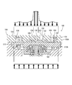
図4、図6は偏心軸部35部分の構造を説明するために拡大したスクロールユニット12部分の縦断側面図、図8は偏心軸部35の拡大縦断側面図である。また、図5、図7は可動スクロール10を透視した(貫通孔61を実線で表示)偏心軸部35の平面図を示している。また、図9は固定スクロール8及び可動スクロール10の中心部の平断面図である(偏心軸部35側(下側)から見た図)。
図4、図6は偏心軸部35部分の構造を説明するために拡大したスクロールユニット12部分の縦断側面図、図8は偏心軸部35の拡大縦断側面図である。また、図5、図7は可動スクロール10を透視した(貫通孔61を実線で表示)偏心軸部35の平面図を示している。また、図9は固定スクロール8及び可動スクロール10の中心部の平断面図である(偏心軸部35側(下側)から見た図)。
前述したように、貫通孔61の上端の入口は基面10bにて開口しているが、この入口は、可動スクロール10の公転旋回運動に応じて、固定スクロール8の内側固定スクロールラップ(ラップ)58の先端により開閉される位置に配置されている。図4はラップ58により開放された状態、図6は閉鎖された状態である。
(1-3)シールリング48の偏心配置
一方、貫通孔61の下端の出口は、シールリング48で仕切られた背圧室68の中心部68bに対応して開口している。この場合、図5に示すシールリング48の円(リング)の中心X1は、偏心軸部35の軸心X2に一致しておらず、偏心配置されている。従って、偏心軸部35の回転中、シールリング48は可動スクロール10に対して公転旋回することになる。他方、シールリング48は背圧室68を中心部68bと外周部68aとに仕切るために可動スクロール10の背面10cに摺動可能に当接しているが、公転旋回することで、可動スクロール10の同じリング状の位置にシールリング48が当接することがなくなり、可動スクロール10の背面10cがシールリング48によって摩耗し難くなる。
一方、貫通孔61の下端の出口は、シールリング48で仕切られた背圧室68の中心部68bに対応して開口している。この場合、図5に示すシールリング48の円(リング)の中心X1は、偏心軸部35の軸心X2に一致しておらず、偏心配置されている。従って、偏心軸部35の回転中、シールリング48は可動スクロール10に対して公転旋回することになる。他方、シールリング48は背圧室68を中心部68bと外周部68aとに仕切るために可動スクロール10の背面10cに摺動可能に当接しているが、公転旋回することで、可動スクロール10の同じリング状の位置にシールリング48が当接することがなくなり、可動スクロール10の背面10cがシールリング48によって摩耗し難くなる。
このように、シールリング48は可動スクロール10に対して公転旋回するため、このシールリング48に対する貫通孔61の位置も可動スクロール10の公転旋回運動中、変化することになるが、貫通孔61の下端の出口は、必ずシールリング48で仕切られた背圧室68の中心部68bに対応するように配置されている。
(1-4)圧力逃がし路81による連通
また、偏心軸部35に対応する位置の可動スクロール10の背面10cには、ラジアル方向に延在する溝78が凹陥形成されており、この溝78内に圧力逃がし路81が構成される。図5は可動スクロール10を透視してこの溝78を表しているが、前述したようなシールリング48の公転旋回により、その内側(偏心軸部35の軸心側)の端部がシールリング48により塞がれた状態(図4、図5)と、シールリング48が溝78を跨ぐ状態(図6、図7)とに変化する。
また、偏心軸部35に対応する位置の可動スクロール10の背面10cには、ラジアル方向に延在する溝78が凹陥形成されており、この溝78内に圧力逃がし路81が構成される。図5は可動スクロール10を透視してこの溝78を表しているが、前述したようなシールリング48の公転旋回により、その内側(偏心軸部35の軸心側)の端部がシールリング48により塞がれた状態(図4、図5)と、シールリング48が溝78を跨ぐ状態(図6、図7)とに変化する。
シールリング48が溝78を跨いだ状態では、溝78の内側の端部と外側の端部とが開放されるため、その内部の圧力逃がし路81は背圧室68の中心部68bと外周部68aを連通する(図6、図7)。一方、シールリング48により溝78の内側の端部が塞がれると、圧力逃がし路81は閉じられ、背圧室68の中心部68bと外周部68aとは非連通状態となる(図4、図5)。
また、貫通孔61と溝78(圧力逃がし路81)の位置関係は、図5、図7に示すように偏心軸部35(軸心X2)に対するシールリング48(中心X1)の偏心方向に延在する線L1上に配置されており、更に、固定スクロール8の内側固定スクロールラップ(ラップ)58の先端により貫通孔61の入口が開放された状態では、図5の如く溝78の内側の端部がシールリング48により塞がれ、背圧室68の中心部68bと外周部68aとが非連通状態となっており、ラップ58の先端により貫通孔61の入口が閉じられたとき、図7の如くシールリング47が溝78を跨いで、圧力逃がし路81により背圧室68の中心部68bと外周部68aとが連通されるように構成されている。
(1-5)膨張室Eの面積重心位置と背圧室68の中心部68bの面積重心位置
次に、図8、図9においてX3は可動スクロール10の旋回中心であり、クランク軸16の軸心と固定スクロール8の内側固定スクロールラップ(ラップ)58の渦巻きの基礎円中心に位置している。また、X4は可動スクロール10の内側可動スクロールラップ(ラップ)66の渦巻きの基礎円中心であり、旋回中心X3から偏心軸部35の偏心方向にずれている。そして、旋回中心X3と可動スクロール10のラップ66の渦巻きの基礎円中心X4との間の距離が可動スクロール10の旋回半径R1となる。
次に、図8、図9においてX3は可動スクロール10の旋回中心であり、クランク軸16の軸心と固定スクロール8の内側固定スクロールラップ(ラップ)58の渦巻きの基礎円中心に位置している。また、X4は可動スクロール10の内側可動スクロールラップ(ラップ)66の渦巻きの基礎円中心であり、旋回中心X3から偏心軸部35の偏心方向にずれている。そして、旋回中心X3と可動スクロール10のラップ66の渦巻きの基礎円中心X4との間の距離が可動スクロール10の旋回半径R1となる。
そして、中心部の膨張室(図9にE1で示す中央室)とその外側の膨張室(図9にE2、E3で示す作動室)を合わせた面積重心の位置は、G1で示すように旋回中心X3から偏心軸部35の偏心方向に、旋回半径R1の1/2ずれた位置になる。
そこで、実施例ではシールリング48で仕切られる背圧室68の中心部68bの中心位置X5(即ち、中心部68の面積重心位置)を、図8に示すように、可動スクロール10の旋回中心X3から、偏心軸部35の偏心方向に、可動スクロール10の旋回半径R1の1/2ずらしている。これにより、膨張部2の膨張室(中央室E1、作動室E2、作動室E3)の面積重心位置G1と、背圧室68の中心部68bの面積重心位置X5とが合致する。これにより、可動スクロール10を転覆させようとするモーメントの発生を効果的に防止することができるようになる。
(2)冷凍サイクルRC
次に、図10は本発明のスクロール型流体機械1を用いた冷凍サイクルRC(実施例)の冷媒回路図を示している。尚、この図では説明のため、スクロール型流体機械1の膨張部2と圧縮部4を分離して示している。スクロール型流体機械1の膨張部2で回収された動力で駆動される圧縮部4は、この冷凍サイクルRCにおいて低段側の圧縮機(低段側の圧縮部)を構成する。この圧縮部4の前述した圧縮側吐出管28は、当該圧縮部4の後段に位置する高段側の圧縮機70の電動機70bで駆動される高段側の圧縮部70aに接続されている。
次に、図10は本発明のスクロール型流体機械1を用いた冷凍サイクルRC(実施例)の冷媒回路図を示している。尚、この図では説明のため、スクロール型流体機械1の膨張部2と圧縮部4を分離して示している。スクロール型流体機械1の膨張部2で回収された動力で駆動される圧縮部4は、この冷凍サイクルRCにおいて低段側の圧縮機(低段側の圧縮部)を構成する。この圧縮部4の前述した圧縮側吐出管28は、当該圧縮部4の後段に位置する高段側の圧縮機70の電動機70bで駆動される高段側の圧縮部70aに接続されている。
この圧縮部70aの後段には、冷媒を冷却するガスクーラ71が接続されており、ガスクーラ71の出口と蒸発器73の入口間に、スクロール型流体機械1の膨張部2と膨張弁72が並列に接続されている。このガスクーラ71からの冷媒は前述した膨張側吸入管24から膨張部2の膨張側吸入室30に取り込まれる。また、スクロール型流体機械1の膨張部2からは膨張側吐出管26を介して冷媒が蒸発器73に送られる。そして、この蒸発器73から出た冷媒が圧縮側吸入管36からスクロール型流体機械1の圧縮部4に吸い込まれる構成とされている。
(3)冷凍サイクルRCの動作
以上の構成で、次にスクロール型流体機械1を含む冷凍サイクルRCの動作を説明する。スクロール型流体機械1の膨張部2が駆動する低段側の圧縮部4で昇圧された中間圧の冷媒(二酸化炭素冷媒)は、圧縮側吐出管28から高段側の圧縮機70に送られ、電動機70bで駆動される圧縮部70aによって更に昇圧され、高圧(超臨界)となる。この高圧の冷媒は超臨界状態のままガスクーラ71で冷却された後、一部は膨張側吸入管24からスクロール型流体機械1の膨張部2に取り込まれ、膨張減圧される。
以上の構成で、次にスクロール型流体機械1を含む冷凍サイクルRCの動作を説明する。スクロール型流体機械1の膨張部2が駆動する低段側の圧縮部4で昇圧された中間圧の冷媒(二酸化炭素冷媒)は、圧縮側吐出管28から高段側の圧縮機70に送られ、電動機70bで駆動される圧縮部70aによって更に昇圧され、高圧(超臨界)となる。この高圧の冷媒は超臨界状態のままガスクーラ71で冷却された後、一部は膨張側吸入管24からスクロール型流体機械1の膨張部2に取り込まれ、膨張減圧される。
尚、残りの冷媒は膨張弁72に送られて膨張減圧される。この膨張弁72はスクロール型流体機械1の膨張部2を通過する冷媒の流量の調整、及び、起動時における差圧の確保のために設けられているものである。
膨張部2において冷媒が等エントロピ的に膨張することによって可動スクロール10が公転旋回運動し、動力が回収される。この可動スクロール10の公転旋回運動によって圧縮部4が低段側の圧縮機として作動することになる。膨張部2で膨張した冷媒は、蒸発器73で加熱された後(或いは、それによって対象を冷却)、圧縮側吸入管36より再びスクロール型流体機械1の圧縮部4に吸引される。
図14は、係る冷凍サイクルRCのp-h線図を示している。この図に示すように、ガスクーラ71で熱交換することによって、点Dから点Cまで冷却された冷媒は、スクロール型流体機械1の膨張部2で等エントロピ的に膨張することによって、液相線LLを超えて湿り蒸気領域に入り、点Bとなる。膨張後、蒸発器73で熱交換され、点Bから点Aまで加熱された冷媒は、スクロール型流体機械1の圧縮部4で点Aから点A1まで圧縮された後、高段側の圧縮機70の圧縮部70aで点A1から点Dまで圧縮される。
このように、高段側の圧縮機70の圧縮部70aで冷凍サイクルRCの圧縮過程の一部(高段側)を担い、スクロール型流体機械1の圧縮部4で圧縮過程の残り(低段側)を担う。圧縮部4におけるエンタルピ差hA1-hA分の圧縮動力は、膨張部2における回収動力によって賄われることになる。
(3-1)背圧室68の中心部68bと外周部68aの背圧
次に、図11~図13を参照しながら、スクロール型流体機械1の可動スクロール10の背圧制御について説明する。前述したように、シールリング48によって仕切られた背圧室68の外周部68aには、圧縮部4の吐出圧力(前述した中間圧)に保たれた冷媒が供給される。一方、シールリング48によって仕切られた背圧室68の中心部68bには、高段側の圧縮機70の圧縮部70aで圧縮された高圧に保たれた冷媒が貫通孔61から供給される。これにより、背圧室68の外周部68aから圧縮部4の吐出圧力で、また、中心部68bからは高段側の圧縮機70で圧縮された高圧で、可動スクロール10は固定スクロール8に対して押圧付勢される。
次に、図11~図13を参照しながら、スクロール型流体機械1の可動スクロール10の背圧制御について説明する。前述したように、シールリング48によって仕切られた背圧室68の外周部68aには、圧縮部4の吐出圧力(前述した中間圧)に保たれた冷媒が供給される。一方、シールリング48によって仕切られた背圧室68の中心部68bには、高段側の圧縮機70の圧縮部70aで圧縮された高圧に保たれた冷媒が貫通孔61から供給される。これにより、背圧室68の外周部68aから圧縮部4の吐出圧力で、また、中心部68bからは高段側の圧縮機70で圧縮された高圧で、可動スクロール10は固定スクロール8に対して押圧付勢される。
ここで、前述したように、可動スクロール10の基面10bの中心部には、高段側の圧縮機70の吐出圧力が加わり、外側に向かうに従って圧力が低下し、膨張していく。この圧力を図11に矢印で示す(この図において、矢印の長さは同様に圧力の大きさを示している)。一方、背圧室68においてはその中心部68bに高段側の圧縮機70の吐出圧力(高圧)に保たれた冷媒が供給され、外周部68aには圧縮部4の吐出圧力(中間圧)に保たれた冷媒が供給される。
これにより、図11に示すように可動スクロール10を固定スクロール8から引き離そうとする力(図11の上側に示す基面10bに加わる力)と、それに対抗して可動スクロール10を固定スクロール8に押し付ける力(図11の下側に示す背圧)とが、可動スクロール10の略全域において略一致するかたちとなり、効率の低下を防止しながら、可動スクロール10の基板10aが撓んでしまう不都合を解消することができるようになる。
(3-2)背圧の調整
また、前述したように膨張部2における膨張過程での圧力変化の特性は、膨張部2に吸い込まれる冷媒(作動流体)の温度によって異なって来る。即ち、膨張部2の入口における冷媒の温度が高い場合、図11の上側に示すように膨張過程の圧力の低下が緩慢となるため、可動スクロール10を固定スクロール8から引き離そうとする力は大きくなる。しかしながら、膨張によって回収される動力も大きくなるため、圧縮部4における仕事量も増大するため、圧縮部4の吐出圧力も高くなる。
また、前述したように膨張部2における膨張過程での圧力変化の特性は、膨張部2に吸い込まれる冷媒(作動流体)の温度によって異なって来る。即ち、膨張部2の入口における冷媒の温度が高い場合、図11の上側に示すように膨張過程の圧力の低下が緩慢となるため、可動スクロール10を固定スクロール8から引き離そうとする力は大きくなる。しかしながら、膨張によって回収される動力も大きくなるため、圧縮部4における仕事量も増大するため、圧縮部4の吐出圧力も高くなる。
逆に、膨張部2の入口における冷媒の温度が低い場合には、図12の上側に示すように膨張過程の圧力は膨張初期に急激に低下するため、可動スクロール10を固定スクロール8から引き離そうとする力は小さくなる。そして、膨張によって回収される動力も小さくなるため、圧縮部4における仕事量も減少し、圧縮部4の吐出圧力も低下する。
一方、本発明では可動スクロール01の背面側に形成された背圧室68をシールリング48により中心部68bと外周部68aとに仕切り、背圧室68の中心部68bに高段側の圧縮機70で圧縮された高圧に保たれた冷媒を供給し、背圧室68の外周部68aには低段側の圧縮部4の吐出圧力に保たれた冷媒を供給しているので、膨張部2の入口における冷媒の温度が高い場合は圧縮部4の仕事量が増大し、その吐出圧力も高くなって背圧室68の外周部68aに供給される圧力は上昇し、膨張部2の入口における冷媒の温度が低い場合は圧縮部4の仕事量が減少し、その吐出圧力も低くなって背圧室68の外周部68aに供給される圧力も低下することになる。
即ち、膨張部2の入口における冷媒の温度が高く、可動スクロール10を固定スクロール8から引き離そうとする力が大きくなるときは、背圧室68の外周部68aに供給される圧力が上昇し、膨張部2の入口における冷媒の温度が低く、可動スクロール10を固定スクロール8から引き離そうとする力が小さくなるときは、背圧室68の外周部68aに供給される圧力も低下するようになり、図11、図12の上側と下側の矢印で示す力を、自動的にバランスさせることが可能となる。
これにより、別途複雑な調整装置等を設けることなく、可動スクロール10に背圧を適切に印加して高効率な運転を実現することが可能となる。これは実施例のような膨張部2と圧縮部4とが一体化された単板式のスクロール型流体機械1において、二酸化炭素を冷媒として使用する場合に特に有効である。
また、実施例ではシールリング48を偏心軸部35の上面(端面)に設けて可動スクロール10の背面に摺動可能に当接させ、この可動スクロール10に形成した貫通孔61により、高圧に保たれた冷媒を背圧室68の中心部68bに供給しているので、背圧室68に高圧を供給する構造を著しく簡素化することが可能となる。
(3-3)貫通孔61の閉鎖と圧力逃がし路81の開放
また、前述した如く貫通孔61の上端の入口は、可動スクロール10の公転旋回運動に応じて、固定スクロール8の内側固定スクロールラップ(ラップ)58の先端により開閉される。この開閉のタイミングについて、前述した図9を参照しながら説明する。図9は一回の膨張過程において、可動スクロール10がクランク角150°程の角度に旋回した位置を示している。このとき、各ラップ58、66間に形成される膨張室Eのうち、中心部の膨張室E(図9の中央室E1)には、膨張側吸入管24から膨張側吸入室30に吸入された高段側の圧縮機70で圧縮されて高圧に保たれた冷媒が流入する。
また、前述した如く貫通孔61の上端の入口は、可動スクロール10の公転旋回運動に応じて、固定スクロール8の内側固定スクロールラップ(ラップ)58の先端により開閉される。この開閉のタイミングについて、前述した図9を参照しながら説明する。図9は一回の膨張過程において、可動スクロール10がクランク角150°程の角度に旋回した位置を示している。このとき、各ラップ58、66間に形成される膨張室Eのうち、中心部の膨張室E(図9の中央室E1)には、膨張側吸入管24から膨張側吸入室30に吸入された高段側の圧縮機70で圧縮されて高圧に保たれた冷媒が流入する。
その後、中央室E1の容積が拡大していき、クランク角0°付近で外側の膨張室E(図9の作動室E2、E3)が分離される。分離された後、作動室E2、E3は更に容積が拡大するため、作動室E2、E3内の冷媒は膨張していき、その圧力は急速に低下していく。前述した図17、図18における高圧の部分はこの中央室E1の圧力であり、クランク角0°付近から急激に低下するのは、中央室から分離された後の作動室E2、E3の圧力を示している。
ラップ58は或る膨張過程において、中央室E1から作動室E2、E3が分離される前の段階では、貫通孔61の入口を開放している。そして、クランク角0°付近で中央室E1から作動室E2、E3が分離され、それらの内部の冷媒が膨張し始めて図14の液相線LLを超え、湿り蒸気領域となった後、クランク角とすると24°付近でラップ58が貫通孔61の入口を閉じ、その後、クランク角230°付近で再度開くように、貫通孔61は配置されている。
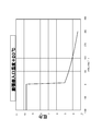
ここで、図21中のL2は可動スクロール10の旋回角度(クランク角)に対する可動スクロール10に加わる軸方向の力の変化を示しており、これは可動スクロール10の中心部を固定スクロール8から引き離そうとする引き離し力である。この引き離し力は、最大となるクランク角0°から11°程にかけて急激に低下し、その後徐々に上昇していって、360°(次の0°)で最大となる変化を示す。これは中央室E1と各作動室E2、E3内の冷媒の圧力から生じる力の合計であるため、このように変化することになる。
これに対して、ラップ58は、クランク角24°付近までは貫通孔61の入口を開いており、圧力逃がし路81は背圧室68の中心部68bと外周部68aを連通しない。従って、中心部68bには貫通孔61から高圧の冷媒が流入し、可動スクロール10の中心部が固定スクロール8に押し付けられる押付力は高圧となる。その後、冷媒が液相線LLを超えて湿り蒸気領域となった後、貫通孔61の入口はラップ58で閉じられ、シールリング48が溝78を跨ぐため、圧力逃がし路81は背圧室68の中心部68bと外周部68aとを連通する。
これにより、図21に実線L3で示すように背圧室68の中心部68bから可動スクロール10の中心部が固定スクロール8に押し付けられる押付力は圧縮部4の吐出圧力まで下げられる。その後、引き離し力L2の上昇に伴い、クランク角230°付近でラップ58は貫通孔61の入口を開き、圧力逃がし路81は中心部68bと外周部68aとを連通しなくなるので、中心部68bからの押付力は高圧に戻される。
これにより、可動スクロール10の中心部に対する引き離し力が大きくなるクランク角では貫通孔61の入口を開放させておいて背圧室68の中心部68bに高圧を供給し、中心部68bと外周部68aを連通させずに、可動スクロール10の中心部を引き離そうとする引き離し力に対抗し、引き離し力が減少するクランク角では、貫通孔61の入口を固定スクロール8の内側固定スクロールラップ58により閉じて高圧の供給を停止し、中心部68bと外周部68aを連通させて、可動スクロール10全体において背圧を圧縮部4の吐出圧力まで下げることができる。
この状態が図13に示されている。このように、可動スクロール10の中心部を引き離そうとする引き離し力L2の低下に合わせて中心部68bへの高圧の供給を停止し、中心部68bと外周部68aを連通することにより、可動スクロール10の中心部への過剰な背圧印加(図21に破線L4で示す)による固定スクロール8への可動スクロール10の過剰な押付力の発生を回避し(L3)、運転効率の低下を防止することが可能となる。
特に、貫通孔61の入口を、膨張室E内の冷媒が液相線LLを越えて湿り蒸気領域となった後に閉じるようにしているので、確実に可動スクロール10の中心部への引き離し力L2が小さくなった後に、中心部の背圧を下げることができるようになり、的確なタイミングで背圧室68の中心部68bへの高圧印加を停止することができるようになる。
また、貫通孔61の入口が閉じられたとき、シールリング48が溝78を跨ぐため、圧力逃がし路81は背圧室68の中心部68bと外周部68aとを連通するので、背圧室68の中心部68bへの高圧印加を停止したことに合わせて中心部68bと外周部68aが連通され、図13の下側の矢印で示すように、背圧は可動スクロール10の全域において圧縮部4の吐出圧力まで下げられる。これにより、可動スクロール10の中心部の引き離し力L2が急激に低下するのに合わせて、背圧室68の圧力を中心部68bと外周部68aで均一化し、過剰な押し付け力の発生を確実に防止することができるようになる。
また、実施例では可動スクロール10の背面10cに形成された溝78内に圧力逃がし路81を構成し、シールリング48が溝78の内側の端部を塞いでいる状態で背圧室68の中心部68bと外周部68aを非連通状態とし、シールリング48が溝78を跨ぐことで溝78の両端部を開放し、圧力逃がし路81によって背圧室68の中心部68bと外周部68aとを連通するように構成したので、構造の著しい簡素化を図ることが可能となる。
尚、実施例では所謂単板式の圧縮機一体型スクロール膨張機をスクロール型流体機械の例に採り上げて本発明を適用したが、請求項1の発明ではそれに限らず、膨張部と圧縮部とが駆動軸によって連結されたかたちのスクロール型流体機械にも本発明は有効である。
1 スクロール型流体機械
2 膨張部
4 圧縮部(低段側)
8 固定スクロール
10 可動スクロール
12 スクロールユニット
16 クランク軸
35 偏心軸部
42 給油路
48 シールリング(シール部材)
50 ボス
58 内側固定スクロールラップ
61 貫通孔
68 背圧室
68a 外周部
68b 中心部
70 圧縮機(高段側)
78 溝
81 圧力逃がし路
E 膨張室
P 圧縮室
RC 冷凍サイクル
2 膨張部
4 圧縮部(低段側)
8 固定スクロール
10 可動スクロール
12 スクロールユニット
16 クランク軸
35 偏心軸部
42 給油路
48 シールリング(シール部材)
50 ボス
58 内側固定スクロールラップ
61 貫通孔
68 背圧室
68a 外周部
68b 中心部
70 圧縮機(高段側)
78 溝
81 圧力逃がし路
E 膨張室
P 圧縮室
RC 冷凍サイクル
Claims (10)
- 各基板の各基面にそれぞれ渦巻き状のラップが対向して形成された固定スクロール及び可動スクロールから構成され、両スクロールの前記各ラップ間に形成された膨張室で作動流体を膨張させることにより、前記可動スクロールを公転旋回運動させて動力を回収する膨張部と、該膨張部で回収された動力で前記作動流体を圧縮する低段側の圧縮部とを備え、高段側の圧縮機で圧縮された高圧の前記作動流体を前記膨張部の中心部より吸入するスクロール流体機械において、
前記可動スクロールの背面側に形成された背圧室と、
該背圧室を中心部と外周部とに仕切るシール部材とを備え、
前記背圧室の中心部に前記高圧に保たれた前記作動流体を供給し、前記背圧室の外周部には前記圧縮部の吐出圧力に保たれた前記作動流体を供給することを特徴とするスクロール型流体機械。 - 前記圧縮部は、前記膨張部の外側における前記両スクロールの前記各ラップ間に形成された圧縮室で前記作動流体を圧縮することを特徴とする請求項1に記載のスクロール型流体機械。
- 可動スクロールの背面側より突出するボスと、クランク軸と、該クランク軸の端部に形成され、前記ボスに摺動且つ回転可能に嵌挿された偏心軸部とを備え、
前記シール部材を前記偏心軸部の端面に設けて前記可動スクロールの背面に摺動可能に当接させ、該可動スクロールに形成した貫通孔により前記高圧に保たれた作動流体を前記背圧室の中心部に供給することを特徴とする請求項1又は請求項2に記載のスクロール型流体機械。 - 前記可動スクロールの旋回運動に応じて、前記固定スクロールのラップにより前記貫通孔の入口が開閉されることを特徴とすることを特徴とする請求項3に記載のスクロール型流体機械。
- 前記貫通孔の入口は、前記膨張室内の作動流体が液相線を越えて湿り蒸気領域となった後に閉じられるよう構成したことを特徴とする請求項4に記載のスクロール型流体機械。
- 前記貫通孔の入口が閉じられたとき、前記背圧室の中心部と外周部とを連通する圧力逃がし路を備えたことを特徴とする請求項4又は請求項5に記載のスクロール型流体機械。
- 前記可動スクロールの背面に形成された溝により前記圧力逃がし路を構成し、前記シール部材が前記溝の端部を塞いでいる状態では前記背圧室の中心部と外周部は非連通状態となり、前記シール部材が前記溝を跨ぐことで前記溝の両端部が開放され、前記背圧室の中心部と外周部が連通されるよう構成したことを特徴とする請求項6に記載のスクロール型流体機械。
- 前記シール部材はリング状を成し、前記偏心軸部の端面に偏心配置されていることを特徴とする請求項3乃至請求項7のうちの何れかに記載のスクロール型流体機械。
- 前記シール部材で仕切られる前記背圧室の中心部を、前記可動スクロールの旋回中心から、前記偏心軸部の偏心方向に、前記可動スクロールの旋回半径の1/2ずらしたことを特徴とする請求項3乃至請求項8のうちの何れかに記載のスクロール型流体機械。
- 前記作動流体として二酸化炭素を使用したことを特徴とする請求項1乃至請求項9のうちの何れかに記載のスクロール型流体機械。
Priority Applications (1)
| Application Number | Priority Date | Filing Date | Title |
|---|---|---|---|
| DE112014005641.3T DE112014005641T5 (de) | 2013-12-11 | 2014-12-10 | Schneckentyp-Fluidmaschine |
Applications Claiming Priority (2)
| Application Number | Priority Date | Filing Date | Title |
|---|---|---|---|
| JP2013256091A JP6241605B2 (ja) | 2013-12-11 | 2013-12-11 | スクロール型流体機械 |
| JP2013-256091 | 2013-12-11 |
Publications (1)
| Publication Number | Publication Date |
|---|---|
| WO2015087908A1 true WO2015087908A1 (ja) | 2015-06-18 |
Family
ID=53371209
Family Applications (1)
| Application Number | Title | Priority Date | Filing Date |
|---|---|---|---|
| PCT/JP2014/082668 Ceased WO2015087908A1 (ja) | 2013-12-11 | 2014-12-10 | スクロール型流体機械 |
Country Status (3)
| Country | Link |
|---|---|
| JP (1) | JP6241605B2 (ja) |
| DE (1) | DE112014005641T5 (ja) |
| WO (1) | WO2015087908A1 (ja) |
Cited By (5)
| Publication number | Priority date | Publication date | Assignee | Title |
|---|---|---|---|---|
| WO2017043471A1 (ja) * | 2015-09-09 | 2017-03-16 | サンデンホールディングス株式会社 | スクロール型流体機械及びそれを用いた冷凍装置 |
| CN108386355A (zh) * | 2018-05-04 | 2018-08-10 | 江西氟斯新能源科技有限公司 | 一种无油涡旋空气压缩机 |
| CN110185615A (zh) * | 2019-04-29 | 2019-08-30 | 苏州为山之环境技术有限公司 | 具有消音结构的密封组件且与横隔板固定的涡旋压缩机 |
| CN112963354A (zh) * | 2021-04-22 | 2021-06-15 | 重庆超力高科技股份有限公司 | 动涡盘、背压结构和二氧化碳压缩机 |
| CN116044753A (zh) * | 2023-01-05 | 2023-05-02 | 珠海格力电器股份有限公司 | 动涡盘组件及具有其的涡旋压缩机 |
Families Citing this family (6)
| Publication number | Priority date | Publication date | Assignee | Title |
|---|---|---|---|---|
| KR101612419B1 (ko) * | 2015-09-18 | 2016-04-19 | 윤진목 | 공전 스크롤 롤링 지지구를 구비한 스크롤 유체기계 |
| CN107575380B (zh) * | 2016-07-05 | 2020-05-05 | 艾默生环境优化技术(苏州)有限公司 | 涡旋压缩机 |
| JP2019023439A (ja) * | 2017-07-24 | 2019-02-14 | サンデン・オートモーティブコンポーネント株式会社 | スクロール型流体機械 |
| JP6711331B2 (ja) * | 2017-08-11 | 2020-06-17 | 株式会社Soken | スクロール圧縮機 |
| JP7233935B2 (ja) * | 2019-01-16 | 2023-03-07 | サンデン株式会社 | スクロール型流体機械 |
| KR102630535B1 (ko) * | 2022-03-03 | 2024-01-29 | 엘지전자 주식회사 | 스크롤 압축기 |
Citations (5)
| Publication number | Priority date | Publication date | Assignee | Title |
|---|---|---|---|---|
| US20030150223A1 (en) * | 2002-02-13 | 2003-08-14 | Yan Tang | Scroll expressor |
| JP2003307188A (ja) * | 2002-04-12 | 2003-10-31 | Anest Iwata Corp | 圧縮部と膨張部を備えたスクロール式流体機械 |
| JP2010133260A (ja) * | 2008-12-02 | 2010-06-17 | Sanden Corp | スクロール型流体機械 |
| WO2012029203A1 (ja) * | 2010-09-02 | 2012-03-08 | 三菱電機株式会社 | 膨張機および冷凍サイクル装置 |
| JP2012052527A (ja) * | 2010-08-04 | 2012-03-15 | Sanden Corp | スクロール型流体機械 |
Family Cites Families (1)
| Publication number | Priority date | Publication date | Assignee | Title |
|---|---|---|---|---|
| EP2522932A1 (en) * | 2010-01-07 | 2012-11-14 | Mitsubishi Electric Corporation | Refrigeration cycling device and expander installed in same |
-
2013
- 2013-12-11 JP JP2013256091A patent/JP6241605B2/ja not_active Expired - Fee Related
-
2014
- 2014-12-10 DE DE112014005641.3T patent/DE112014005641T5/de not_active Withdrawn
- 2014-12-10 WO PCT/JP2014/082668 patent/WO2015087908A1/ja not_active Ceased
Patent Citations (5)
| Publication number | Priority date | Publication date | Assignee | Title |
|---|---|---|---|---|
| US20030150223A1 (en) * | 2002-02-13 | 2003-08-14 | Yan Tang | Scroll expressor |
| JP2003307188A (ja) * | 2002-04-12 | 2003-10-31 | Anest Iwata Corp | 圧縮部と膨張部を備えたスクロール式流体機械 |
| JP2010133260A (ja) * | 2008-12-02 | 2010-06-17 | Sanden Corp | スクロール型流体機械 |
| JP2012052527A (ja) * | 2010-08-04 | 2012-03-15 | Sanden Corp | スクロール型流体機械 |
| WO2012029203A1 (ja) * | 2010-09-02 | 2012-03-08 | 三菱電機株式会社 | 膨張機および冷凍サイクル装置 |
Cited By (6)
| Publication number | Priority date | Publication date | Assignee | Title |
|---|---|---|---|---|
| WO2017043471A1 (ja) * | 2015-09-09 | 2017-03-16 | サンデンホールディングス株式会社 | スクロール型流体機械及びそれを用いた冷凍装置 |
| CN108386355A (zh) * | 2018-05-04 | 2018-08-10 | 江西氟斯新能源科技有限公司 | 一种无油涡旋空气压缩机 |
| CN110185615A (zh) * | 2019-04-29 | 2019-08-30 | 苏州为山之环境技术有限公司 | 具有消音结构的密封组件且与横隔板固定的涡旋压缩机 |
| CN110185615B (zh) * | 2019-04-29 | 2024-05-10 | 苏州为山之环境技术有限公司 | 具有消音结构的密封组件且与横隔板固定的涡旋压缩机 |
| CN112963354A (zh) * | 2021-04-22 | 2021-06-15 | 重庆超力高科技股份有限公司 | 动涡盘、背压结构和二氧化碳压缩机 |
| CN116044753A (zh) * | 2023-01-05 | 2023-05-02 | 珠海格力电器股份有限公司 | 动涡盘组件及具有其的涡旋压缩机 |
Also Published As
| Publication number | Publication date |
|---|---|
| JP6241605B2 (ja) | 2017-12-06 |
| JP2015113760A (ja) | 2015-06-22 |
| DE112014005641T5 (de) | 2016-09-22 |
Similar Documents
| Publication | Publication Date | Title |
|---|---|---|
| JP6241605B2 (ja) | スクロール型流体機械 | |
| KR100840048B1 (ko) | 용적형 유체 기계 | |
| JP6302813B2 (ja) | スクロール圧縮機及びこれを用いた冷凍サイクル装置 | |
| JPWO2008139667A1 (ja) | 冷凍サイクル装置及びそれに用いる流体機械 | |
| JP4866887B2 (ja) | スクロール圧縮機 | |
| JP2012188978A (ja) | スクロール圧縮機 | |
| JP2004190559A (ja) | 容積型膨張機及び流体機械 | |
| WO2011019021A1 (ja) | スクロール型流体機械 | |
| CN114026328A (zh) | 涡旋压缩机及使用了该涡旋压缩机的空调机 | |
| JP4584306B2 (ja) | スクロール膨張機 | |
| US8690555B2 (en) | Two-stage rotary expander, expander-compressor unit, and refrigeration cycle apparatus | |
| KR102565824B1 (ko) | 스크롤 압축기 | |
| WO2017043471A1 (ja) | スクロール型流体機械及びそれを用いた冷凍装置 | |
| JP5771739B2 (ja) | スクロール圧縮機 | |
| CN102395759A (zh) | 流体机械及制冷循环装置 | |
| JP6393115B2 (ja) | スクロール型流体機械 | |
| JP6393116B2 (ja) | スクロール型流体機械 | |
| JP2012241680A (ja) | スクロール圧縮機 | |
| JP2010138749A (ja) | スクロール型流体機械 | |
| JP2015165116A (ja) | スクロール型圧縮機 | |
| JP7702647B2 (ja) | スクロール圧縮機 | |
| JP7486085B2 (ja) | スクロール圧縮機及び機器 | |
| JP4888222B2 (ja) | 流体機械およびそれを備えた冷凍サイクル装置 | |
| WO2016031278A1 (ja) | スクロール型流体機械及びそれを用いた冷凍装置 | |
| JP5270993B2 (ja) | スクロール型流体機械 |
Legal Events
| Date | Code | Title | Description |
|---|---|---|---|
| 121 | Ep: the epo has been informed by wipo that ep was designated in this application |
Ref document number: 14869445 Country of ref document: EP Kind code of ref document: A1 |
|
| WWE | Wipo information: entry into national phase |
Ref document number: 112014005641 Country of ref document: DE |
|
| 122 | Ep: pct application non-entry in european phase |
Ref document number: 14869445 Country of ref document: EP Kind code of ref document: A1 |