WO2015087907A1 - アルミニウム合金製ターボコンプレッサホイール用素形材およびターボコンプレッサホイールの製造方法 - Google Patents
アルミニウム合金製ターボコンプレッサホイール用素形材およびターボコンプレッサホイールの製造方法 Download PDFInfo
- Publication number
- WO2015087907A1 WO2015087907A1 PCT/JP2014/082663 JP2014082663W WO2015087907A1 WO 2015087907 A1 WO2015087907 A1 WO 2015087907A1 JP 2014082663 W JP2014082663 W JP 2014082663W WO 2015087907 A1 WO2015087907 A1 WO 2015087907A1
- Authority
- WO
- WIPO (PCT)
- Prior art keywords
- compressor wheel
- forging
- turbo compressor
- aluminum alloy
- diameter
- Prior art date
- Legal status (The legal status is an assumption and is not a legal conclusion. Google has not performed a legal analysis and makes no representation as to the accuracy of the status listed.)
- Ceased
Links
Images







Classifications
-
- F—MECHANICAL ENGINEERING; LIGHTING; HEATING; WEAPONS; BLASTING
- F04—POSITIVE - DISPLACEMENT MACHINES FOR LIQUIDS; PUMPS FOR LIQUIDS OR ELASTIC FLUIDS
- F04D—NON-POSITIVE-DISPLACEMENT PUMPS
- F04D29/00—Details, component parts, or accessories
- F04D29/02—Selection of particular materials
- F04D29/023—Selection of particular materials especially adapted for elastic fluid pumps
-
- B—PERFORMING OPERATIONS; TRANSPORTING
- B21—MECHANICAL METAL-WORKING WITHOUT ESSENTIALLY REMOVING MATERIAL; PUNCHING METAL
- B21K—MAKING FORGED OR PRESSED METAL PRODUCTS, e.g. HORSE-SHOES, RIVETS, BOLTS OR WHEELS
- B21K3/00—Making engine or like machine parts not covered by sub-groups of B21K1/00; Making propellers or the like
- B21K3/04—Making engine or like machine parts not covered by sub-groups of B21K1/00; Making propellers or the like blades, e.g. for turbines; Upsetting of blade roots
-
- B—PERFORMING OPERATIONS; TRANSPORTING
- B22—CASTING; POWDER METALLURGY
- B22D—CASTING OF METALS; CASTING OF OTHER SUBSTANCES BY THE SAME PROCESSES OR DEVICES
- B22D11/00—Continuous casting of metals, i.e. casting in indefinite lengths
-
- B—PERFORMING OPERATIONS; TRANSPORTING
- B22—CASTING; POWDER METALLURGY
- B22D—CASTING OF METALS; CASTING OF OTHER SUBSTANCES BY THE SAME PROCESSES OR DEVICES
- B22D11/00—Continuous casting of metals, i.e. casting in indefinite lengths
- B22D11/001—Continuous casting of metals, i.e. casting in indefinite lengths of specific alloys
- B22D11/003—Aluminium alloys
-
- B—PERFORMING OPERATIONS; TRANSPORTING
- B23—MACHINE TOOLS; METAL-WORKING NOT OTHERWISE PROVIDED FOR
- B23P—METAL-WORKING NOT OTHERWISE PROVIDED FOR; COMBINED OPERATIONS; UNIVERSAL MACHINE TOOLS
- B23P15/00—Making specific metal objects by operations not covered by a single other subclass or a group in this subclass
- B23P15/02—Making specific metal objects by operations not covered by a single other subclass or a group in this subclass turbine or like blades from one piece
-
- C—CHEMISTRY; METALLURGY
- C22—METALLURGY; FERROUS OR NON-FERROUS ALLOYS; TREATMENT OF ALLOYS OR NON-FERROUS METALS
- C22C—ALLOYS
- C22C21/00—Alloys based on aluminium
-
- C—CHEMISTRY; METALLURGY
- C22—METALLURGY; FERROUS OR NON-FERROUS ALLOYS; TREATMENT OF ALLOYS OR NON-FERROUS METALS
- C22C—ALLOYS
- C22C21/00—Alloys based on aluminium
- C22C21/02—Alloys based on aluminium with silicon as the next major constituent
-
- C—CHEMISTRY; METALLURGY
- C22—METALLURGY; FERROUS OR NON-FERROUS ALLOYS; TREATMENT OF ALLOYS OR NON-FERROUS METALS
- C22C—ALLOYS
- C22C21/00—Alloys based on aluminium
- C22C21/12—Alloys based on aluminium with copper as the next major constituent
- C22C21/16—Alloys based on aluminium with copper as the next major constituent with magnesium
-
- C—CHEMISTRY; METALLURGY
- C22—METALLURGY; FERROUS OR NON-FERROUS ALLOYS; TREATMENT OF ALLOYS OR NON-FERROUS METALS
- C22C—ALLOYS
- C22C21/00—Alloys based on aluminium
- C22C21/12—Alloys based on aluminium with copper as the next major constituent
- C22C21/18—Alloys based on aluminium with copper as the next major constituent with zinc
-
- C—CHEMISTRY; METALLURGY
- C22—METALLURGY; FERROUS OR NON-FERROUS ALLOYS; TREATMENT OF ALLOYS OR NON-FERROUS METALS
- C22F—CHANGING THE PHYSICAL STRUCTURE OF NON-FERROUS METALS AND NON-FERROUS ALLOYS
- C22F1/00—Changing the physical structure of non-ferrous metals or alloys by heat treatment or by hot or cold working
- C22F1/04—Changing the physical structure of non-ferrous metals or alloys by heat treatment or by hot or cold working of aluminium or alloys based thereon
- C22F1/043—Changing the physical structure of non-ferrous metals or alloys by heat treatment or by hot or cold working of aluminium or alloys based thereon of alloys with silicon as the next major constituent
-
- C—CHEMISTRY; METALLURGY
- C22—METALLURGY; FERROUS OR NON-FERROUS ALLOYS; TREATMENT OF ALLOYS OR NON-FERROUS METALS
- C22F—CHANGING THE PHYSICAL STRUCTURE OF NON-FERROUS METALS AND NON-FERROUS ALLOYS
- C22F1/00—Changing the physical structure of non-ferrous metals or alloys by heat treatment or by hot or cold working
- C22F1/04—Changing the physical structure of non-ferrous metals or alloys by heat treatment or by hot or cold working of aluminium or alloys based thereon
- C22F1/057—Changing the physical structure of non-ferrous metals or alloys by heat treatment or by hot or cold working of aluminium or alloys based thereon of alloys with copper as the next major constituent
-
- F—MECHANICAL ENGINEERING; LIGHTING; HEATING; WEAPONS; BLASTING
- F01—MACHINES OR ENGINES IN GENERAL; ENGINE PLANTS IN GENERAL; STEAM ENGINES
- F01D—NON-POSITIVE DISPLACEMENT MACHINES OR ENGINES, e.g. STEAM TURBINES
- F01D5/00—Blades; Blade-carrying members; Heating, heat-insulating, cooling or antivibration means on the blades or the members
- F01D5/02—Blade-carrying members, e.g. rotors
- F01D5/04—Blade-carrying members, e.g. rotors for radial-flow machines or engines
- F01D5/043—Blade-carrying members, e.g. rotors for radial-flow machines or engines of the axial inlet- radial outlet, or vice versa, type
- F01D5/048—Form or construction
-
- F—MECHANICAL ENGINEERING; LIGHTING; HEATING; WEAPONS; BLASTING
- F02—COMBUSTION ENGINES; HOT-GAS OR COMBUSTION-PRODUCT ENGINE PLANTS
- F02B—INTERNAL-COMBUSTION PISTON ENGINES; COMBUSTION ENGINES IN GENERAL
- F02B39/00—Component parts, details, or accessories relating to, driven charging or scavenging pumps, not provided for in groups F02B33/00 - F02B37/00
-
- F—MECHANICAL ENGINEERING; LIGHTING; HEATING; WEAPONS; BLASTING
- F04—POSITIVE - DISPLACEMENT MACHINES FOR LIQUIDS; PUMPS FOR LIQUIDS OR ELASTIC FLUIDS
- F04D—NON-POSITIVE-DISPLACEMENT PUMPS
- F04D29/00—Details, component parts, or accessories
- F04D29/26—Rotors specially for elastic fluids
- F04D29/266—Rotors specially for elastic fluids mounting compressor rotors on shafts
-
- F—MECHANICAL ENGINEERING; LIGHTING; HEATING; WEAPONS; BLASTING
- F04—POSITIVE - DISPLACEMENT MACHINES FOR LIQUIDS; PUMPS FOR LIQUIDS OR ELASTIC FLUIDS
- F04D—NON-POSITIVE-DISPLACEMENT PUMPS
- F04D29/00—Details, component parts, or accessories
- F04D29/26—Rotors specially for elastic fluids
- F04D29/28—Rotors specially for elastic fluids for centrifugal or helico-centrifugal pumps for radial-flow or helico-centrifugal pumps
- F04D29/284—Rotors specially for elastic fluids for centrifugal or helico-centrifugal pumps for radial-flow or helico-centrifugal pumps for compressors
-
- F—MECHANICAL ENGINEERING; LIGHTING; HEATING; WEAPONS; BLASTING
- F05—INDEXING SCHEMES RELATING TO ENGINES OR PUMPS IN VARIOUS SUBCLASSES OF CLASSES F01-F04
- F05D—INDEXING SCHEME FOR ASPECTS RELATING TO NON-POSITIVE-DISPLACEMENT MACHINES OR ENGINES, GAS-TURBINES OR JET-PROPULSION PLANTS
- F05D2220/00—Application
- F05D2220/40—Application in turbochargers
-
- F—MECHANICAL ENGINEERING; LIGHTING; HEATING; WEAPONS; BLASTING
- F05—INDEXING SCHEMES RELATING TO ENGINES OR PUMPS IN VARIOUS SUBCLASSES OF CLASSES F01-F04
- F05D—INDEXING SCHEME FOR ASPECTS RELATING TO NON-POSITIVE-DISPLACEMENT MACHINES OR ENGINES, GAS-TURBINES OR JET-PROPULSION PLANTS
- F05D2230/00—Manufacture
- F05D2230/20—Manufacture essentially without removing material
- F05D2230/21—Manufacture essentially without removing material by casting
-
- F—MECHANICAL ENGINEERING; LIGHTING; HEATING; WEAPONS; BLASTING
- F05—INDEXING SCHEMES RELATING TO ENGINES OR PUMPS IN VARIOUS SUBCLASSES OF CLASSES F01-F04
- F05D—INDEXING SCHEME FOR ASPECTS RELATING TO NON-POSITIVE-DISPLACEMENT MACHINES OR ENGINES, GAS-TURBINES OR JET-PROPULSION PLANTS
- F05D2230/00—Manufacture
- F05D2230/20—Manufacture essentially without removing material
- F05D2230/25—Manufacture essentially without removing material by forging
-
- F—MECHANICAL ENGINEERING; LIGHTING; HEATING; WEAPONS; BLASTING
- F05—INDEXING SCHEMES RELATING TO ENGINES OR PUMPS IN VARIOUS SUBCLASSES OF CLASSES F01-F04
- F05D—INDEXING SCHEME FOR ASPECTS RELATING TO NON-POSITIVE-DISPLACEMENT MACHINES OR ENGINES, GAS-TURBINES OR JET-PROPULSION PLANTS
- F05D2300/00—Materials; Properties thereof
- F05D2300/10—Metals, alloys or intermetallic compounds
- F05D2300/17—Alloys
- F05D2300/173—Aluminium alloys, e.g. AlCuMgPb
-
- F—MECHANICAL ENGINEERING; LIGHTING; HEATING; WEAPONS; BLASTING
- F05—INDEXING SCHEMES RELATING TO ENGINES OR PUMPS IN VARIOUS SUBCLASSES OF CLASSES F01-F04
- F05D—INDEXING SCHEME FOR ASPECTS RELATING TO NON-POSITIVE-DISPLACEMENT MACHINES OR ENGINES, GAS-TURBINES OR JET-PROPULSION PLANTS
- F05D2300/00—Materials; Properties thereof
- F05D2300/50—Intrinsic material properties or characteristics
- F05D2300/502—Thermal properties
-
- F—MECHANICAL ENGINEERING; LIGHTING; HEATING; WEAPONS; BLASTING
- F05—INDEXING SCHEMES RELATING TO ENGINES OR PUMPS IN VARIOUS SUBCLASSES OF CLASSES F01-F04
- F05D—INDEXING SCHEME FOR ASPECTS RELATING TO NON-POSITIVE-DISPLACEMENT MACHINES OR ENGINES, GAS-TURBINES OR JET-PROPULSION PLANTS
- F05D2300/00—Materials; Properties thereof
- F05D2300/50—Intrinsic material properties or characteristics
- F05D2300/518—Ductility
-
- F—MECHANICAL ENGINEERING; LIGHTING; HEATING; WEAPONS; BLASTING
- F05—INDEXING SCHEMES RELATING TO ENGINES OR PUMPS IN VARIOUS SUBCLASSES OF CLASSES F01-F04
- F05D—INDEXING SCHEME FOR ASPECTS RELATING TO NON-POSITIVE-DISPLACEMENT MACHINES OR ENGINES, GAS-TURBINES OR JET-PROPULSION PLANTS
- F05D2300/00—Materials; Properties thereof
- F05D2300/60—Properties or characteristics given to material by treatment or manufacturing
Definitions
- the present invention relates to an aluminum alloy turbo compressor wheel shaped material used for a turbocharger used in an internal combustion engine of a transport device such as an automobile, and a method for manufacturing the turbo compressor wheel.
- This application claims priority based on Japanese Patent Application No. 2013-258638 for which it applied to Japan on December 13, 2013, and uses the content here.
- a turbocharger used in an internal combustion engine for transportation equipment has a compressor wheel (also referred to as an impeller) that is coupled to a turbine that rotates by a pressure of exhaust gas through a connecting shaft. Is sent to the compressor housing to compress the air, and this compressed air is sent into the combustion chamber to improve the combustion efficiency of the internal combustion engine, thereby improving the output of the internal combustion engine and purifying the exhaust gas.
- a turbocharger is usually divided into a turbine side (exhaust gas) and a compressor side (intake side), and a heat insulating bearing is arranged between them.
- a compressor wheel is arranged in the center of the compressor housing.
- the compressor wheel of such a turbocharger device has a plurality of curved thin blade portions (blade portions) for scavenging air radially and one side of a spiral on the outer peripheral side of a rotating shaft portion that is generally conical.
- the structure is formed so as to form a part.
- the compressor wheel is arrange
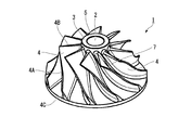
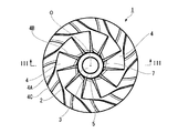
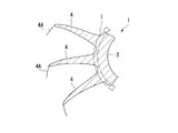
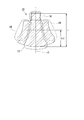
- FIG. 1 to FIG. 3 A typical example of a compressor wheel is shown in FIG. 1 to FIG. 3 as an example of an overall outline of its basic shape, and an enlarged cross-sectional view of the main part is shown in FIG.
- a compressor wheel 1 includes a plurality of blades radially arranged on the outer peripheral side of a substantially conical rotating shaft portion 3 having a shaft hole 2 for press-fitting a shaft connected to a turbine rotor (not shown). It has a structure in which the portion 4 is integrally formed.
- the edge portions of the blade portion 4 it is inclined in a twisted curved shape (relative to the rotation center axis O) between the air intake side edge portion 4B on the air intake side and the air discharge side edge portion 4C.
- the edge portion (edge portion) 4A that is inclined in a twisted manner is an edge portion that forms a gap (so-called tip clearance) with the compressor housing, that is, a portion called a tip edge portion.
- An end portion on the small diameter side of the rotary shaft portion 3 is a boss portion 5 protruding from the end portion of the blade portion 4. Further, from the outer edge portion of the rotating shaft portion 3 (except mainly in the vicinity of the boss portion 5 on one end side of the rotating shaft portion 3), the portion 7 continuing to the blade portion 4, in other words, the outer peripheral portion of the rotating shaft portion 3
- the portion that rises from the blade portion 4 to the blade portion 4 can be referred to as a blade root portion 7.
- a finer shape is given to each part or fine convex parts and concave parts other than the above are formed, but here only basic parts are shown, and details are shown. The shape is omitted.
- the overall dimensions are, for example, a maximum outer diameter of about 30 to 150 mm with reference to the rotation axis O, and a direction along the rotation axis O.
- the maximum length is often about 20 to 100 mm.
- a turbocharger compressor wheel is required to have high temperature, high strength and high rigidity at a high speed exceeding 10,000 rpm at a high temperature of about 150 ° C., and at the same time, it is lightweight to reduce energy loss. It is necessary to be.
- the dynamic balance during high-speed rotation is good, and therefore that it has a uniform density in the circumferential direction (rotation direction).
- the compressor wheel it is effective to increase the efficiency by increasing the temperature of the compressed air, and to transfer the heat from the turbine side to the compressed air, so that the heat dissipation (thermal conductivity) is good. desired.
- the blade part 4 is required to be thin (usually less than 1 mm thick) in order to ensure lightness. Therefore, it is required that the blade portion 4 is not easily deformed by high-speed rotation, and therefore, the high-temperature strength and rigidity of the blade portion 4 are required. Particularly, the tip edge portion 4A in the vicinity of the tip edge portion 4A is extremely extreme. Since it is usually thin, it is desirable that the portion has sufficiently high temperature strength and rigidity.
- the blade root portion (portion continuing from the rotating shaft portion 3 to the blade portion 4) 7 is a portion where stress is concentrated during rotation, and therefore, durability and reliability for continuous use at high speed rotation are ensured. In order to satisfy it, notch fatigue strength is required to be high.
- the rotating shaft portion 3 is a portion that supports a plurality of blade portions 4, and when assembling the turbocharger, the shaft is usually press-fitted into the shaft hole 2 of the rotating shaft portion 3, where the rotating shaft It is desired that the portion 3 is much thicker than the blade portion, and that the boss portion 5 on the one end side of the rotating shaft portion 3 has good strength and elongation so that cracking does not occur when the shaft is press-fitted. .
- the compressor wheel as a whole has high strength and high rigidity at high temperature, excellent dynamic balance and light weight at high speed rotation, and at the same time, the function of each part, different shape and thickness It is desirable that each part has different characteristics depending on the situation.
- an aluminum alloy As a material for the compressor wheel of a conventional turbocharger, an aluminum alloy is generally used from the viewpoints of lightness, thermal conductivity, and workability, among the required characteristics as described above.
- this type of aluminum alloy compressor wheel has been cast directly from a molten aluminum alloy by a casting method called a lost wax method (also called a precision casting method). It has been usual to finish the compressor wheel by appropriately finishing the material such as cutting (for example, Patent Document 1).
- an extruded material (extruded billet) of an aluminum alloy is used as a raw material, and the extruded billet is subjected to a forging process to obtain a forged shape material, followed by a cutting process.
- a method of finishing by adding for example, Patent Document 2.
- Patent Document 3 As in Patent Document 2, it is assumed that a rotating body such as a compressor wheel of a turbocharger is obtained from an aluminum alloy material by forging. In that case, in the forging process, A method has been proposed in which forging is performed uniformly uniformly, that is, forging is performed in three directions to obtain a forged raw material having no dead zone portion and having a metal flow portion substantially uniformly.
- the turbocharger compressor wheel has a thick portion around the shaft hole (rotating shaft portion) and a thin portion radially extending from the thick portion (blade portion) as described above.
- the blade portion is particularly thin with a tip portion (near the chip edge portion) of a very thin thickness of less than 1 mm and a complicated curved surface having a special shape.
- the molten aluminum alloy does not rotate sufficiently in the thin wall part, so internal defects such as porosity and oxide occur in the thin wall part. In many cases, a minute shape portion cannot be formed accurately.
- the extruded material in a compressor wheel obtained by forging using an extruded material as a raw material, the extruded material has a fibrous structure extending long along the extrusion direction. When viewed in a cross section perpendicular to the extrusion direction, it has a substantially uniform structure in the radial direction (structure with a substantially uniform particle diameter in the radial direction).
- the maximum diameter portion that is included usually has a substantially homogeneous structure in the radial direction when viewed in a cross section orthogonal to the central axis of rotation of the compressor wheel. In other words, this means that the different characteristics desired for each part of the compressor wheel cannot be fully satisfied.
- Patent Document 3 even when forging in three directions, a uniform structure is obtained as a whole. Therefore, it is difficult to sufficiently satisfy different characteristics desired for each part of the compressor wheel. It was. In this case, although a generally homogeneous structure can be obtained, the structure is not necessarily uniform in the circumferential direction on the basis of the rotation center position of the compressor wheel because of forging from different directions over three stages. There is a risk that the product will be inferior in dynamic balance during high-speed rotation of the compressor wheel.
- the present invention has been made against the background of the above circumstances, and is generally excellent in high-temperature strength and rigidity, and at the same time excellent in dynamic balance during high-speed rotation, and according to different required characteristics and desired characteristics for each part.
- the present inventors have conducted various experiments and studies on the aluminum alloy turbo compressor wheel shaped material, and as a result, as a material, a thin rod by continuous casting, that is, rapid solidification. It is optimal to use a cast material obtained by continuous casting, and in particular, as the cast structure in the cross-sectional direction perpendicular to the casting direction, the structure of the center part is the coarsest and the outer peripheral part is the densest structure. It has been found that it is optimal to use the continuous cast bar as a raw material. It has also been found that it is effective to use a continuous casting bar with such a small diameter as a raw material, and forging it into a shaped material for a turbo compressor wheel. These findings have led to the invention of the aluminum alloy turbo compressor wheel shaped material and the invention of the turbo compressor wheel manufacturing method.
- the present invention provides each aspect described in the following (1) to (21).
- An aluminum alloy turbo compressor wheel shaped material that has a maximum cast structure at the outer periphery and the casting direction of the material is along the rotation center axis direction of the compressor wheel.
- the “shape material” means a cutting process for forming a blade part, a drilling process for forming a shaft hole, and a whole for finishing a turbo compressor wheel product. It means a member in a stage before performing a finishing process such as a typical polishing process.
- the overall shape is the shape of a rotating body that is an axis subject to the rotation center axis O of the compressor wheel of the product, and has an outer surface shape that is larger than the outer shape of the compressor wheel of the product. Shape corresponding to the outer shape of the wheel (similar to the outer shape of the compressor wheel; however, there are no groove-like recesses between the blades, and the front edge of the blades is included.
- a shape that can be referred to as a truncated truncated cone shape or a bell shape Therefore, when manufacturing the shaped material of the above (1), as described in (13) described later, the raw material (small-diameter continuous cast bar) is subjected to roughing which is machining, Usually, it is processed into a truncated truncated cone shape or a bell shape as described above.
- the central portion of the material includes a portion that is supposed to be a blade root in a final product turbo compressor wheel, and the outer peripheral portion is a blade on the outer peripheral side of the blade root in the final product turbo compressor wheel.
- An aluminum alloy turbo compressor wheel shaped material including a part to be a part.
- the shape of the base material is usually a shape substantially along the outer shape of the compressor wheel of the product, that is, a truncated truncated cone shape or a bell shape. It becomes. Therefore, the “original material” in (4) usually means a member that has been forged by forged closed die forging.
- the continuous cast bar of the material is an aluminum alloy having a cast structure in which the number of transverse average grain boundary crossings seen in a cross section orthogonal to the casting direction is minimum at the center and maximum at the outer periphery. Forming material for turbo compressor wheels.
- the central portion of the continuous cast bar includes a portion that is supposed to be a blade root in a final product turbo compressor wheel, and the outer peripheral portion is outer than the blade root in the final product turbo compressor wheel.
- An aluminum alloy turbo compressor wheel shaped material including a portion that is supposed to be a blade portion on the side.
- the central portion of the forged material includes a portion that is supposed to be a blade root in the final product turbo compressor wheel, and the outer peripheral portion is located on the outer peripheral side of the blade root in the turbo compressor wheel of the final product.
- An aluminum alloy turbo compressor wheel shaped material including a portion that is supposed to be a blade portion.
- the outer diameter of the material is ⁇ 2 with respect to the inner diameter of the portion corresponding to the maximum diameter portion of the compressor wheel or the inner diameter of the portion corresponding to the blade portion minimum diameter side end of the compressor wheel in the closed forging die.
- An aluminum alloy turbo compressor wheel shaped material that is used in a range of 0.0 mm to -0.10 mm.
- the following aspects are aspects relating to a method for manufacturing an aluminum alloy turbo compressor wheel.
- a method for producing a turbo compressor wheel comprising:
- a method for producing a turbo compressor wheel comprising:
- the outer diameter corresponds to the inner diameter of the maximum diameter portion of the compressor wheel product to be obtained in the forging die or the blade portion minimum diameter side end of the compressor wheel product wheel to be obtained.
- the position of the small-diameter material with respect to the forging die is positioned by the inner peripheral wall of the portion corresponding to the maximum diameter portion or the inner peripheral wall of the portion corresponding to the blade portion minimum diameter side end portion in the forging die.
- the base material for an aluminum alloy turbo compressor wheel according to the present invention is excellent in high-temperature strength and rigidity as a whole when a turbocharger compressor wheel is manufactured using the base material, and at the same time, dynamic balance at high speed rotation. In addition, it is possible to obtain a compressor wheel having excellent performance according to different required characteristics and desired characteristics for each part. According to the method for manufacturing a turbo compressor wheel of the present invention, a compressor wheel for an aluminum alloy turbocharger having such excellent performance can be actually manufactured.
- FIG. 3 is a longitudinal sectional view taken along line III-III in FIG. 2.
- FIG. 4 is an enlarged cross-sectional view taken along line IV-IV in FIG. 3.
- It is a longitudinal cross-sectional view which shows an example of the shape material for turbocompressor wheels made from an aluminum alloy by this invention, especially an example of the shape material which consists of a forging up material.
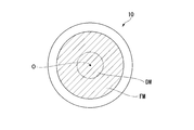
- It is a schematic diagram which shows an example of the structure
- FIG. 14 is a transverse sectional view taken along line XIV-XIV in FIG. 13.
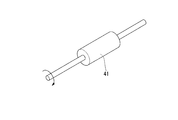
- mold longitudinal cross-section side which shows the 2nd example of the relationship between the raw material for forge in the forge process in the 2nd Embodiment of the manufacturing method of the turbo compressor wheel of this invention, and a forge die. It is a schematic diagram which shows the metal flow by the forging in the 2nd example shown in FIG. It is an approximate solution for showing the measuring method of the dynamic balance at the time of high-speed rotation about the shape material which used the thin diameter continuous cast bar as a raw material. It is a rough solution for showing the measuring method of the dynamic balance at the time of high-speed rotation about the basic shape material which used the forge rising material as a raw material.
- the type and composition of the material alloy is not particularly limited as long as it is an aluminum alloy that can satisfy general characteristics required for a compressor wheel, such as high-temperature strength, rigidity, workability, and machinability.
- T6 treatment solution treatment-artificial aging treatment
- T7 treatment solution treatment-stabilization treatment Therefore, it is preferable to increase the strength, and it is desirable to select an aluminum alloy most suitable for these heat treatments.
- the alloy of the raw material is, for example, an Al—Si eutectic alloy, particularly “AHS” alloy (registered trademark) containing Al—Si—Cu—Mg as a basic component, or a so-called 2000 alloy.
- a known Al—Cu—Mg alloy is optimal.
- the above-mentioned “AHS” is a registered trademark of Showa Denko KK for aluminum alloy for high strength and high wear resistance use.
- the 2000 series alloy means an alloy whose initial number is “2” as a 4-digit alloy number in Japanese JIS standard, US AA standard or German DIN standard. .
- Al—Si eutectic alloy represented by the above-mentioned “AHS” alloy is an alloy in which eutectic Si particles are crystallized in a matrix, and its component composition is Si: 9 to 12% (mass by mass). %, The same applies hereinafter), Cu: 3.5 to 4.5%, Mg: 0.4 to 0.8%, Fe: 0.15 to 0.3%, Mn: 0.05 to 0.25% It is desirable to contain it, and the balance consists of Al and inevitable impurities.
- Such an Al—Si eutectic alloy has a composition close to that of a housing alloy (generally a JIS standard ADC12 alloy) surrounding a compressor wheel in a turbocharger, so that the thermal expansion coefficient of the compressor wheel is equal to the thermal expansion coefficient of the housing. It becomes equivalent. Therefore, the clearance of the narrow gap (so-called tip clearance) between the tip of the blade portion (tip edge portion) of the compressor wheel and the inner surface of the housing can be maintained constant, which is optimal as a material for the compressor wheel.
- a housing alloy generally a JIS standard ADC12 alloy
- such an Al—Si eutectic alloy represented by the “AHS” alloy crystallizes eutectic Si particles in the matrix, but the eutectic Si particles are fine, and in the present invention, the fine eutectic Si particles are fine. Since a continuous cast bar having a diameter is used as a raw material, the cast structure is refined by rapid solidification as will be described later. Therefore, it is excellent in terms of high-temperature strength, rigidity, fatigue strength, notch sensitivity, and the like, and also from these points, it is excellent as a material for the compressor wheel shape material of the present invention.
- Si is distributed as eutectic Si in the matrix, improves the rigidity, and coexists with Mg to precipitate Mg 2 Si particles to improve the strength of the aluminum alloy. Further, the eutectic Si particles are dispersed in the matrix, so that the chip breaking property is improved and the machinability is improved. If Si is less than 9%, these effects cannot be obtained sufficiently. On the other hand, if Si exceeds 12%, primary Si is crystallized and forgeability is lowered. Therefore, Si is preferably in the range of 9 to 12%. The Si amount is preferably within a range of 10 to 11% even within a range of 9 to 12%.
- the eutectic Si particles preferably have an average particle size of 3 ⁇ m or less and a standard deviation of particle size of 1 ⁇ m or less. If the average particle size of the eutectic Si particles exceeds 3 ⁇ m, or if the standard deviation of the particle size exceeds 1 ⁇ m, not only the forgeability is deteriorated, but also desirable high temperature strength, rigidity, fatigue strength, and notch sensitivity are obtained. There is a risk of disappearing.
- the average particle diameter of the eutectic Si particles is more preferably in the range of 1.5 to 2 ⁇ m.
- the particle diameter of the eutectic Si particles is 3 ⁇ m or less” or “in the range of 1.5 to 2 ⁇ m” means that the substantial particle size distribution is in these ranges. It means that 95% or more, preferably 98% or more, of eutectic Si particles of all the eutectic Si particles measured by the image processing method of microscopic microscopic observation photographs are within these ranges.
- Fe precipitates Al-Fe-based and Al-Fe-Si-based particles, refines the recrystallized grains during hot forging, and thins and fines the blades in the subsequent cutting (finishing). It is possible to easily process into a simple shape. If the Fe content is less than 0.15%, this effect is small. On the other hand, if it exceeds 0.3%, Al-Fe and Al-Fe-Si coarse crystals are increased and forgeability is lowered.
- the amount of Fe is preferably in the range of 0.15 to 0.3%.
- the Fe amount is preferably 0.15 to 0.25%.
- Cu If Cu is contained, CuAl 2 particles are precipitated, which contributes to improving the strength of the aluminum alloy. In order to obtain the effect of improving the strength sufficiently, it is desirable to add 3.5% or more of Cu. On the other hand, if the Cu content exceeds 4.5%, the forgeability is lowered. It is preferably in the range of 3.5 to 4.5%. The Cu content is more preferably 3.8 to 4.2%.
- Mg If Mg is contained, it coexists with Si and precipitates Mg 2 Si particles, thereby contributing to improvement of the strength of the aluminum alloy. If the Mg content is less than 0.4%, the effect of improving the strength is small, while if the Mg content exceeds 0.8%, the forgeability decreases. Therefore, the Mg content is preferably within the range of 0.4 to 0.8%. The Mg amount is more preferably in the range of 0.4 to 0.6%.
- Mn If Mn is contained, Al—Mn and Al—Mn—Fe—Si particles are precipitated, and the recrystallized grains are refined during hot forging, and then the second stage forging (cold forging). ) The forging processability of the process is improved, and in the subsequent cutting process (finishing process), it is possible to easily process the blade portion and the like into a thin and fine shape.
- the Mn content is less than 0.05%, this effect is small.
- it exceeds 0.25% Al—Mn and Al—Mn—Fe—Si A coarse crystals are increased, and forgeability is reduced.
- the Mn content is preferably in the range of 0.05 to 0.25%.
- the amount of Mn is more preferably 0.05 to 0.1%.
- each element of Si, Fe, Cu, Mg, and Mn in the Al—Si eutectic alloy may basically be Al and inevitable impurities.
- Cr, Zr , V may be contained in an amount of 0.1% or less, and the total amount with other unavoidable impurities may be 2% or less. If these elements are added, particles such as Al—Cr, Al—Cr—Fe—Si, Al—Zr, and Al—V are precipitated, and the recrystallized grains are refined during hot forging. In the subsequent cutting process (finishing process), the blade portion and the like can be easily processed into a thin and fine shape.
- Ti 0.01 to 0.3% (preferably 0.01 to 0.2%, more preferably 0.002 to 0.1%)
- B 0.0001 to 0.05% (preferably 0.005 to 0.1%)
- Sr 0.001 to 0.2% (preferably 0.005 to 0.1%, more preferably 0.005) Or 0.05%)
- Ti and B are added, the structure of the ingot can be refined, cracking of the ingot during casting can be prevented, and forgeability can be further improved.
- Sr is added, eutectic Si can be refined and forgeability can be improved.
- Al-Cu-Mg alloy 2000 based alloy
- it is in the 2xxx range as defined in the JIS standard, AA standard, DIN standard, or ISO standard. Alloys such as JIS 2014 alloy, JIS 2017 alloy, JIS 2024 alloy, JIS 2218 alloy, JIS 2618 alloy, etc., or alloys similar to these standard alloys (which basically fall within the category of Al-Cu-Mg alloys, It can be selected appropriately from those slightly deviating from the component composition of the standard alloy.
- JIS 2618 alloy is representative as an alloy for forging in applications where high-temperature strength is required, and can be suitably used as a material for a compressor wheel shape material in the present invention.
- an alloy (alloy B2 described later) in which the components (particularly Ni and Cu contents) of the 2618 alloy are changed can be suitably used.
- Specific component compositions of this type of Al—Cu—Mg alloy include: Si: 0.1 to 0.8%, Cu: 1.8 to 4.5%, Mg: 1.2 to 2.0 %, Fe: 0.18 to 1.5%, Mn: 0.05 to 1.2%, Ni: 0.05 to 1.5%, and 0.1% each as other inevitable impurities or additive elements
- Si Si: 0.1 to 0.8%
- Cu 1.8 to 4.5%
- Mg 1.2 to 2.0 %
- Fe 0.18 to 1.5%
- Mn 0.05 to 1.2%
- Ni 0.05 to 1.5%
- 0.1% each as other inevitable impurities or additive elements it is desirable to use an aluminum alloy having a total of 2% or less and the balance being aluminum. Even within this range, it is preferable to adjust the amounts of Cu and Ni so that the total amount of Cu and Ni components (Cu + Ni) is within the range of 3.0 to 4.0%.
- Si is distributed as eutectic Si in the matrix, improves the rigidity, and coexists with Mg to precipitate Mg2Si particles to improve the strength of the aluminum alloy. In order to acquire the effect, it is necessary to contain Si 0.1% or more. On the other hand, if the amount of Si exceeds 0.8%, the elongation is lowered and the forgeability is lowered. Therefore, Si is preferably within the range of 0.1 to 0.8%. Since Si is an element that contributes to dispersion strengthening at about 150 ° C., it is 0 when used at a temperature higher than the operating temperature (about 150 ° C.) in a general turbocharger (for example, a temperature of about 200 ° C. or higher). Desirably, the content is within the range of 1 to 0.25%, while when used at a general use temperature of about 150 ° C., the range of 0.3 to 0.7% is preferable.
- Cu If Cu is contained, CuAl 2 particles are precipitated, which contributes to improving the strength of the aluminum alloy. In order to sufficiently obtain the effect of improving the strength, it is desirable to add Cu by 1.8% or more. On the other hand, if the Cu content exceeds 4.5%, the forgeability deteriorates. It is preferably in the range of 1.8 to 4.5%.
- the Cu content is an element that improves the strength at a use temperature (about 150 ° C.) in a general turbocharger. Therefore, a compressor wheel element used at a general turbo charger use temperature (about 150 ° C.) is used.
- the Cu amount is relatively large, for example, 3.0 to 3.0 in view of balancing the Ni content to a small amount as described later (that is, from the viewpoint of compensating for the strength reduction due to the small amount of Ni). It is desirable to make it contain in 4.0% of range.
- the amount of Cu is relatively small, for example, 1. It is desirable to make it contain in the range of 9 to 2.7%.
- Mg If Mg is contained, it coexists with Si and precipitates Mg 2 Si particles, thereby contributing to improvement of the strength of the aluminum alloy. If the Mg content is less than 1.2%, the effect of improving the strength is small, while if the Mg content exceeds 2.0%, the forgeability is lowered. Therefore, the Mg content is preferably in the range of 1.2 to 2.0%. The amount of Mg is more preferably in the range of 1.3 to 1.8%.
- Fe is a component that contributes to improving high-temperature strength. If the amount is less than 0.18%, sufficient high-temperature strength improvement effect cannot be obtained. If 1.5% or more, brittleness caused by excess Fe is not obtained. Occurs and cracks occur during forging. Therefore, the amount of Fe is set in the range of 0.18% to 1.5%. In order to sufficiently improve the high temperature strength, the Fe content is preferably 0.8% to 1.3%.
- Mn is an element that increases the strength. When the content is 0.05% or less, the effect of improving the strength is small. When the content is 1% or more, Fe—Mn-based crystallized matter is generated, and the toughness is lowered. Therefore, the content is determined to be 0.05 to 1.2%.
- Ni When Ni is contained, the dispersion strengthening of the Al—Ni compound is effective in improving the high temperature strength, particularly in the temperature range around 200 ° C. or higher. If the Ni content is less than 0.05%, the effect of improving the strength by adding Ni cannot be obtained. On the other hand, if the Ni content exceeds 1.5%, the toughness decreases, so the Ni content is 0.05 to 1.5%. Within the range of is preferable. However, the addition of Ni is effective in improving the strength at about 200 ° C. or more, but if the amount of Ni increases, the strength decreases conversely at the operating temperature of a general turbocharger (about 150 ° C.).
- the Ni content As a raw material for a compressor wheel shaped material used at a general turbocharger operating temperature (about 150 ° C.), it is preferable to limit the Ni content to a small amount, in which case the Ni content is 0.3% or less. More preferably, it is desirable to regulate to 0.1% or less. On the other hand, when the operating temperature is about 200 ° C. or higher than the operating temperature of a general turbocharger, the Ni content should be relatively large, for example within the range of 0.9 to 1.2%. Is desirable.
- each element of Si, Cu, Mg, Fe, Mn, and Ni in the Al—Cu—Mg alloy may basically be Al and inevitable impurities.
- Cr, , Zr, or V may be contained in an amount of 0.1% or less and 2% or less in total with other unavoidable impurities. If these elements are added, particles such as Al—Cr, Al—Cr—Fe—Si, Al—Zr, and Al—V are precipitated, and the recrystallized grains are refined during hot forging. In the subsequent cutting process (finishing process), the blade portion and the like can be easily processed into a thin and fine shape.
- Cu + Ni In the Al—Cu—Mg alloy, the Cu amount and the Ni amount are set so that the total amount of Cu and Ni (Cu + Ni) is within the range of 3.0 to 4.0%. It is more preferable to adjust. When (Cu + Ni) is within this range, an alloy having a better balance between workability, forgeability and strength can be obtained.
- Ti 0.01 to 0.3% (preferably 0.01 to 0.2%, more preferably 0.002 to 0.1%)
- B 0.0001 to 0.05% (preferably 0.005 to 0.1%)
- Sr 0.001 to 0.2% (preferably 0.005 to 0.1%, more preferably 0.005) Or 0.05%)
- Ti and B are added, the structure of the ingot can be refined, cracking of the ingot during casting can be prevented, and forgeability can be further improved.
- Sr is added, eutectic Si can be refined and forgeability can be improved.
- Al—Cu—Mg alloy in the case of a general operating temperature of about 150 ° C., Si: 0.3 to 0.7%, Fe: 0.18 to 0.3%, Cu: 3.0 to 4.0%, Mg: 1.3 to 1.8%, Mn: 0.6 to 1.2%, Ti : It is desirable to select an aluminum alloy containing 0.01 to 0.05% and in which Ni is regulated to 0.3% or less or 0.1% or less (hereinafter referred to as “alloy B2”). When a high temperature (for example, about 200 ° C.
- alloy B1 a 0.04 to aluminum alloys containing 0.1%
- the shaped member for a turbo compressor wheel of the present invention may be made of a continuous casting bar having a small diameter, or the continuous casting bar having a small diameter is used as a forging material, and the forging material is hot. It may be made of a forged material (forged material) subjected to hermetic die forging.
- the shape before roughing remains as a thin bar by continuous casting (however, it is usually a short length corresponding to one compressor wheel). Cut). Then, rough machining such as lathe processing is performed on the short thin rod material, for example, and it is processed into a truncated truncated cone shape or a bell shape to obtain a shaped member for a compressor wheel. Further, in order to actually finish the shaped material into the shape of the compressor wheel, as machining, for example, finishing such as cutting is performed to form a blade portion or a boss hole.
- the overall shape of the forged finished material is a truncated cone corresponding to the final compressor wheel (see FIGS. 1 to 4).
- Forging into a trapezoidal or bell shape That is, it is assumed that the product has a rotating body shape that is an axis subject to the rotation axis O of the compressor wheel of the product and has an outer peripheral surface shape that is slightly larger than the outer shape of the compressor wheel of the product.
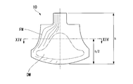
- the details of the forged material (forged material) 10 shown in FIG. 5 will be described later in detail in the section of the manufacturing method. Even when using a forging shaped material (forged finished material) in this way, in order to actually finish the shaped material into the shape of the compressor wheel, finishing processing such as cutting is performed.
- the base material or forging material made of a small-diameter continuous cast bar has a casting direction (hence, a length direction as the bar) along the rotation center axis direction of the compressor wheel as the final product.
- the circumferential direction average grain-boundary crossing number seen in the cross section orthogonal to the casting direction has the casting structure which becomes the minimum in the center part of a cross section, and becomes the maximum in an outer peripheral part.
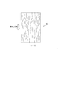
- FIG. 6 and FIG. 7 schematically show the cross-sectional structure of the thin continuous cast bar 20 having a small diameter used for the compressor wheel shape material (or forging material).
- a bar cylindrical rod
- the bar 20 obtained by continuous casting has an equiaxed crystal structure in which the metal structure (casting structure) is elongated radially from the center of the cylindrical axis of the bar 20 in the outer diameter direction. Grain boundaries are distributed almost evenly, and the grain boundary density in the circumferential direction is uniform.
- Grain boundaries are the places where transition metals such as Fe, Ni, and Mn segregate, and therefore the density distribution (roughness) of the grain boundaries affects the density of the material, and therefore the weight balance in the circumferential direction.
- the continuous cast bar has a uniform grain boundary density in the circumferential direction, so that the dynamic balance at the time of high speed rotation required for the compressor wheel of the product is excellent.
- the density distribution (roughness) of the grain boundaries in the cross section of the cylindrical bar can be evaluated by the number of circumferential average grain boundary crossings in each part in the radial direction. The number defines the density of the tissue in the radial direction.
- the structure of the extruded shaped material 15 is elongated in a fiber shape in the extrusion direction. Therefore, the difference in structure between the extrusion direction and the direction orthogonal thereto is extremely large. Therefore, even after forging the extruded material, the influence of the structure difference due to the direction of the extruded material remains, and there is a strong possibility that the mechanical properties will vary depending on the direction.
- the difference in structure between the casting direction and the direction orthogonal thereto is much smaller than that of the extruded material. Therefore, the variation (anisotropy) in mechanical properties depending on the direction can be suppressed to be relatively small.
- the outer peripheral portion Q3 has a structure with a small particle size (that is, a dense structure), and the solidification rate slightly increases as solidification proceeds toward the center. Since it becomes late
- the central portion Q1 of the cross section of the raw material (small-diameter continuous cast bar) 20 is, for example, in a cross section orthogonal to the casting direction as schematically shown on the left side of FIG. It means a region Q1 from the center position O of the cross section to a position P1 having a radius (r / 3) of 1/3 of the material radius r.
- the outer peripheral portion means, for example, a region Q3 from the center position O of the material cross section 12 to a position P2 having a radius (3r / 4) of 3/4 of the material radius r to an outer periphery position P3.
- the region Q2 is a region between the central region Q1 and the outer peripheral region Q3.
- the circumferential direction average grain boundary crossing number (C) in the raw material (small-diameter continuous cast bar) 20 is a cross section orthogonal to the casting direction of the raw material 20 as shown in FIG.
- a circle concentric circle; for example, a circle of reference numeral 12
- a portion (arc) 12A having a length L on the circumference crosses the grain boundary 14 (see FIG. 9).
- the circumferential direction average grain boundary crossing number (C) of the outer peripheral part and the central part as described above is a measured value in a circle at a representative position (radius) in each of the regions Q1, Q2, and Q3.
- the value measured on the circumference having a radius of 2 mm from the center is taken as the value at the center, and the measurement on the circumference at a position of 2 mm radially inward from the outer peripheral surface is performed.
- the value is a value at the outer peripheral portion, and in practice, measurement at such a representative position is sufficient.
- a plurality of concentric circles (a plurality of sample circles; desirably three or more sample circles) are equally spaced in the radial direction within the region. )
- the density of the cast structure (the density of grain boundaries) in the cross section of the raw material (thin diameter continuous cast bar) 20 may be determined.
- the grain boundaries can be observed by performing an etching process for observing the metal structure on the cross-section of a continuous cast bar with a small diameter. And measure the number of grain boundaries crossed by the arc on the concentric circle of the cross section by observing with a metal microscope, or obtain an image of the cross section after the etching process by photography etc. May be binarized as necessary, and the number of grain boundaries crossed by arcs on concentric circles in the cross section may be measured.
- the number of transverse average grain boundary crossings seen in the cross section orthogonal to the casting direction as described above is minimized at the center of the cross section, and at the outer periphery.
- the reason for defining the largest cast structure is as follows.
- the center portion corresponding to the region Q1 from the center position O to the position P1 of the radius (r / 3) of 1/3 of the material radius r is the compressor wheel of the product.
- the part is a part corresponding to the blade part in the compressor wheel of the product.
- the fact that the number of circumferential average grain boundary crossings in the part corresponding to the blade root at the center is small, that is, the structure is relatively sparse, is effective in improving the notch fatigue strength of the blade root.
- the position on the one end side of the rotating shaft part of the compressor wheel is a boss part into which the shaft is press-fitted, but the average grain boundary crossing number of the part is small, that is, the structure is relatively sparse, It becomes possible to make it hard to produce a crack at the time of shaft press-fitting.
- the fact that the number of circumferential average grain boundary crossings in the part corresponding to the blade part in the outer peripheral part is large, that is, the relatively dense structure is that the strength of the thin blade part in the compressor wheel rotating at high speed and Contributes to improved rigidity.
- the continuous cast bar has the density as defined above in the radial direction, so that different performance requirements for each part of the compressor wheel of the product can be satisfied.
- the cast structure of the continuous cast bar into a structure having a roughness as defined above in the radial direction, a circle of a portion that is supposed to be a blade root in the turbo compressor wheel of the final product.
- the number of circumferential average grain boundary crossings is smaller than the circumferential average grain boundary crossing of the part that is expected to become blades in the final product turbo compressor wheel on the outer peripheral side of the blade root. This makes it possible to satisfy different performances required for the blade root and blade in the final turbo compressor wheel.
- the ratio (Nout / Nin) between the circumferential average grain boundary crossing number Nout in the outer peripheral part and the circumferential average grain boundary crossing number Nin in the central part is preferably in the range of 1.3 to 10.
- the difference in the density of the structure in the radial direction of the cross section is not sufficient, so that it can sufficiently satisfy the different required performance of each part in the compressor wheel as described above. There is a risk of disappearing.
- the ratio (Nout / Nin) is practically small in excess of 10, Also, if the ratio (Nout / Nin) exceeds 10, even though different required characteristics of each part can be satisfied, the difference in structure between the central part and the outer peripheral part becomes remarkably large. It may adversely affect the properties and toughness.
- the specific value of the average number of transverse grain boundaries in the circumferential direction varies depending on the casting speed, cooling conditions, casting diameter, alloy composition of the alloy during continuous casting, etc.
- the Al—Si eutectic alloy is generally about 0.5 to 10 and the Al—Cu—Mg alloy is generally about 1 to 30, and usually Within this range, a difference occurs in the average number of transverse grain boundaries in the circumferential direction between the central portion side and the outer peripheral portion side of the continuously cast bar.
- a mode has been described in which a continuous cast bar material having a small diameter is used as a raw material, and a shaped member for a compressor wheel is formed only by machining (rough machining) without performing plastic processing such as forging.
- the shape member for the compressor wheel the above-described small-diameter continuous cast bar may be further subjected to a closed die forging by hot. Even in this case, if the density condition of the structure in the radial direction of the cross section as described above is satisfied at the stage of the continuously cast bar (forging material), the influence remains on the forged material and will be described next. Thus, it becomes possible to easily obtain an appropriate structure as a forged finished material (compressor wheel shaped material).
- the cast structure is crossed in the circumferential average grain boundary of the part that is planned to become the blade root in the turbo compressor wheel of the final product, as described above.
- the number of the structures can be smaller than the number of crossings in the circumferential direction average grain boundary of the portion that is supposed to be a blade portion in the final product turbo compressor wheel on the outer peripheral side of the blade root portion.
- the ratio (Nout / Nin) of the circumferential direction average grain boundary crossing number Nout in the outer peripheral part of the continuous cast bar and the circumferential direction average grain boundary crossing number Nin in the center part is also 1.3 as described above. Within the range of ⁇ 10 is preferred.
- the definition of the outer peripheral part and center part of a continuous cast bar, the definition of the number of circumferential average grain boundary crossings, and the measuring method are as already stated. Furthermore, it is desirable that the above conditions be satisfied for the casting speed during continuous casting and the diameter of the cast bar.
- a forging material consisting of a continuous casting bar with a small diameter is placed in a closed mold so that the forging pressurization direction is along the casting direction of the material and the rotation center axis direction of the compressor wheel.
- the average number of crossings in the circumferential direction seen from the cross-section perpendicular to the forging pressure direction is the smallest at the center, similar to the conditions specified for the continuous cast bar. It is desirable to have a forged structure that is maximum at the outer periphery.
- the average number of crossings in the circumferential direction of the grain boundary is calculated at the half of the total height in the axial direction of the forged material.
- the ratio (Nout / Nin) of the circumferential average grain boundary crossing number of the central part and the outer peripheral part at the position of the half of the total height (Nout / Nin) is 1.3 as in the case of the continuous cast bar already described. Within the range of ⁇ 10 is preferred.
- the definition of the outer peripheral part and the center part of the forged finished material, the definition of the number of circumferential average grain boundary crossings, and the measuring method thereof are the same as in the case of the continuous cast bar already described.
- the circumferential average grain boundary crossing number as viewed in a cross section perpendicular to the forging pressure direction at the position of one half of the total height in the direction along the axial direction.
- the number of circumferential average grain boundary crossings in the part corresponding to the blade root at the center is small, that is, the relatively sparse structure improves the notch fatigue strength of the blade root. It becomes effective. That is, if there are few grain boundaries that are the starting points of notch fatigue failure at the blade root where stress concentrates during high-speed rotation of the compressor wheel, this contributes to improvement of notch fatigue strength.
- the position on the one end side of the rotating shaft part of the compressor wheel is a boss part into which the shaft is press-fitted, but the average grain boundary crossing number of the part is small, that is, the structure is relatively sparse, It becomes possible to make it hard to produce a crack at the time of shaft press-fitting.
- the fact that the number of transverse average grain boundary crossings in the part corresponding to the blade part in the outer peripheral part of the forged material is large, that is, that the structure is relatively dense, is that the thin blade in the compressor wheel rotating at high speed This contributes to improvement of the strength and rigidity of the part.
- the structure of the cross section at the height position in the forged finished material as the compressor wheel shape material satisfies the density condition as defined above in the radial direction, so that the compressor wheel of the product Different required performance for each part can be satisfied.
- the turbo compressor wheel of the final product is obtained by giving the above-mentioned difference in the average number of crossings in the circumferential direction at the center portion and the outer peripheral portion at the position of one half of the total height of the forged material.
- the structure can be smaller than the number of circumferential average grain boundary crossings seen, and this allows different performance required for the blade root and blade in the final turbo compressor wheel. It is the it is possible to meet, respectively.
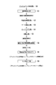
- the shaped member for the turbo compressor wheel of the present invention may be a thin continuous cast bar or a forged material obtained by subjecting the narrow continuous cast bar to hot hermetic forging. It may be. That is, in the former case, a thin continuous cast bar obtained by continuous casting is used as a raw material to finish the compressor wheel through a process as shown in FIG. That is, the above-described aluminum alloy is melted (S0), and a continuous casting bar having a small diameter is obtained by a continuous casting step (S1).
- homogenization treatment step S2 homogenization treatment is performed (homogenization treatment step S2), and then, if necessary, through a roll correction step (S3), a peeling step (S4), and a cutting step (S5), depending on the alloy type
- heat treatment such as T6 treatment or T7 treatment is performed as necessary, and the aluminum alloy compressor wheel shaped material is obtained by a roughing step (S7) for machining into a shaped material shape.
- the base material is subjected to finishing processing (S8) to finish the shape and dimensions of the final product (compressor wheel) by machining such as cutting, and finally the aluminum alloy turbocharger compressor wheel product and To do.
- a continuous casting bar having a small diameter obtained by continuous casting is used as a forging material, and hot forging die forging (S9) is performed on the forging obtained.
- the rising material is subjected to a heat treatment (S6) such as T6 treatment or T7 treatment according to the alloy type as necessary to obtain a compressor wheel shaped material.
- a finishing process (S8) to finish the shape and dimensions of the final product (compressor wheel) by machining such as cutting, and the compressor wheel product is finished.
- the former process and the latter process are for finishing, except whether the hot-sealed die forging step (S9) is sandwiched between them and whether or not there is a roughing step (S7). This is substantially the same except for the amount of processing in the finishing processing step (S8). Therefore, first, each step of the process of FIG. 10 (a process in which a thin continuous cast bar having a small diameter is used as a raw material) will be described, and thereafter, the process of FIG. With respect to the process of forming the raw material, a point different from the process of FIG. 10 (particularly, the forging step (S9)) will be described.
- a continuous casting method in which a thin rod is continuously cast is applied. That is, a molten aluminum alloy adjusted to a predetermined component composition is cast into a small diameter (rod shape: cylindrical bar shape) by a continuous casting method.
- the specific aspect of continuous casting is not particularly limited as long as it is a continuous casting method that can be cast at high speed (thus, if it is a continuous casting method with a high solidification rate), but horizontal continuous casting, vertical continuous casting. Any of these may be used, and a gas-pressing hot top continuous casting method or the like can be suitably applied.
- the bar (cylindrical rod) obtained by continuous casting has a substantially equiaxed crystal structure as described above, and a substantially uniform structure in the circumferential direction. Therefore, the dynamic balance required for the product compressor wheel is also an excellent material.
- the difference in structure between the casting direction and the direction orthogonal thereto is much smaller than that of the extruded material, so that the variation in the mechanical characteristics depending on the direction can be suppressed to be relatively small.
- the continuous casting is desirably performed at a casting speed of 150 mm / min or more so that the outer diameter is 25 mm or more and 120 mm or less.
- the microstructure in the radial direction of the cross section is a fine structure of equiaxed crystals that does not change so much. It is possible to obtain a structure in which the number of directional average grain boundaries is minimum at the central portion and maximum at the outer peripheral portion, that is, a relatively coarse structure at the central portion and a relatively dense structure at the outer peripheral portion.
- the casting speed can be an average of 900 mm / min or more, and in that case, due to the remarkable quenching effect, A finer structure can be obtained.
- ⁇ Homogenization process S2> A homogenization process is performed as needed with respect to the thin continuous casting bar material obtained as described above. If homogenization is performed, the effect of homogenizing segregation during casting can be obtained, and the transition metal element that becomes a recrystallization nucleus does not become coarse, which is preferable from the viewpoint of preventing coarse recrystallization.
- the conditions for the homogenization treatment are not particularly limited, but in the case of an Al—Cu—Mg alloy (2000 alloy), it is preferable to heat to 470 to 520 ° C. for 8 to 24 hours, while Al—Si eutectic crystal In the case of a base alloy, it is preferably heated to 470 to 500 ° C. for 8 to 24 hours.
- Roll straightening process S3 to peeling process S4> After the homogenization treatment, roll correction for correcting the bending of the continuous cast bar is performed with a roll, if necessary, and further peeling (face milling) is performed to remove a casting defect portion and unevenness on the surface.
- the continuous cast bar is cut into a short round bar having a predetermined length. That is, it cut
- Heat treatment step (T6 or T7) S6> When forging is not performed after cutting as described above, heat treatment is usually performed as necessary after cutting.
- a T6 treatment for applying an artificial aging treatment after the solution treatment or a T7 treatment for performing a stabilization treatment after the solution treatment is applied.
- the T6 treatment includes so-called T61 treatment in which cooling (quenching) after heating in the solution treatment is performed by hot water quenching.
- the heat treatment step S6 may be performed before the cutting step S5.
- the heat treatment for the Al—Si eutectic alloy is 480 to 505 ° C. ⁇ 0.5 to 4 hours of heating and holding (solution treatment), and then quenched to a water temperature of 20 to 75 ° C. It is preferable to perform an artificial aging treatment or stabilization treatment at 220 ° C. for 2 hours to 12 hours.
- a roughing process is usually performed by machining such as a lathe process to form the shaped material. That is, since the shape is usually a short columnar shape before the roughing, it is common to obtain the shape of the material by roughing such as lathe. Similar to the shape shown in FIG. 5 as the forged finished material 10, the shape of the shaped material obtained by this roughing process may be substantially truncated frustoconical or bell-shaped.
- finish processing such as cutting for forming the blade part of the outer diameter part and drilling of the shaft hole part (drilling) is performed. .
- general machining may be applied. Note that machining such as cutting in finishing may be machining having a plurality of steps.
- ⁇ Forging process hot sealed die forging S9
- a forging material a small continuous casting bar short
- the center axis of the material is inserted into the forging die cavity so that it coincides with the rotation center axis of the compressor wheel product to be obtained, and the forging pressure direction is along the casting direction during continuous casting of the forging material, Forging is performed by unidirectional pressing to obtain a forged material (original material) 10 as shown in FIG. 5, for example.
- a portion denoted by reference numeral 12 corresponds to the rotating shaft portion 3 in the compressor wheel of the product, and in particular, a portion 14 on one end side thereof is on one end side of the rotating shaft portion 3.
- the portion 16 corresponds to the protruding portion (boss portion) 5, and the portion 16 corresponds to the blade portion 4 in the product compressor wheel, and the portion 18 corresponds to the blade root portion 7 in the product compressor wheel.
- the relationship between the forging die cavity and the forging material during forging is forged by the inner peripheral surface or inner peripheral edge of the cavity (usually the inner peripheral surface or inner peripheral edge of the lower die), as will be described in detail later. So that the forging material is positioned and the center axis of the forging material (the center axis in the direction along the casting direction) coincides with the center axis of the cavity (usually the lower mold), thus the rotation axis of the product compressor wheel It is preferable to center and forge to match.
- the plastic working rate in forging is scheduled to be a blade part in the finishing process with the plastic working rate being less than 20% for the part that is supposed to be a blade root part in the finishing process.
- the plastic working rate is less than 20% for the part that is supposed to be a blade root part in the finishing process.
- part currently performed it is desirable to make a plastic working rate into 20% or more.
- the height (h) of the forged finished material (raw material) 10 is 1 ⁇ 2 of the total height (h) in the direction along the axial direction.
- the plastic working rate of each part measured at the cross-sectional position of the position / 2) may satisfy the above conditions.
- the cross section at the position of half the height (h) in the direction along the axial direction (h) in the direction of the forged material (raw material) 10 is as follows: This is a position where both a relatively inner portion scheduled to be formed and an outer portion (particularly a portion that becomes a thin blade tip portion) expected to become a blade portion appear, and thus h It becomes easy to evaluate the influence of the plastic working rate on the blade root and the thin blade tip by the plastic working rate measured at each part of the cross-sectional position at the position of / 2.
- the plastic working rate measured at the position is specified, for the plastic working rate at such a cross-sectional position, a forging simulation simulating actual forging is performed, and the cross-section of the forging material is made into a lattice shape in the simulation.
- the distance between lattices before and after forging and forging can be measured and estimated by the above formula.
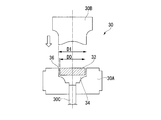
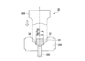
- FIG. 12 shows an example of the relationship between the forging die using the closed forging die and the forging material as described above (first example: an example using a relatively large-diameter forging material). Forging in that case FIG. 13 and FIG. 14 show the metal flow of the material observed with the rising material.
- FIG. 15 shows another example of the relationship between a forging die using a closed forging die and a forging material (second example: an example using a relatively small-diameter forging material).
- FIG. 16 shows the metal flow of the material observed in FIG.
- the closed forging die 30 is a lower die 30 ⁇ / b> A having a cavity 34 into which a forging material (small continuous cast bar material 32) is inserted, and descends toward the lower die 30 ⁇ / b> A.
- the outer diameter D0 of the forging material 32 used for forging is the maximum of the lower die 30A.
- the width of the clearance (gap) 36 between the outer peripheral surface of the forging material 32 and the maximum inner diameter portion of the lower die 30A is set to be in the range of 1.0 mm to 0.05 mm. .
- the outer diameter D0 of the forging material 32 used for forging is lower die.
- D0min D2-2.0mm
- D0max D2-0.10mm It is set to be within the range of.
- the width is set to be in the range of 1.0 mm to 0.05 mm.
- the forging material 32 is simply inserted into the cavity 34 of the lower die 30A, and the center axis of the forging material is substantially cavity (usually the lower die). It can be centered so as to coincide with the central axis of the inner) and substantially coincide with the rotational axis of the compressor wheel of the product, and forging can be performed while maintaining the centered state.
- the metal flow of the material at the time of forging turns into a flow as shown with the thin continuous line inside the forge raising material 10 shown in FIG. That is, the outer peripheral portion to be the blade portion 4 in the compressor wheel, particularly the portion corresponding to the thin-walled tip side of the blade portion 4 is a portion FM with a large metal flow of material, while the center inside the forged finish 10
- the portion (however, the central portion on the side away from the boss portion 5; the portion including the blade mounting portion 7 in the rotating shaft portion 3 of the compressor wheel) becomes a dead metal portion DM substantially free of material flow. .
- the compressor wheel of the product The portion corresponding to the rotating shaft portion 3 and the portion corresponding to the blade root portion 7 at the periphery thereof are a dead metal portion DM, and the portion corresponding to at least the tip portion (thin wall portion) of the blade portion 4 in the compressor wheel of the product is A partial FM with a large flow of material.
- the portion corresponding to the rotating shaft portion 3 of the product and the portion corresponding to the blade root portion 7 at the periphery of the forged material 10 are dead metal portions DM having no metal flow during forging.
- the structure of the continuously cast bar material, which is the raw material, is substantially taken over, and a structure with a lower density than the outer peripheral portion is left. Therefore, as already described for continuous cast bars, the grain boundary that becomes the starting point of notch fatigue fracture is reduced at the root of the blade where stress concentrates during high-speed rotation of the compressor wheel, contributing to the improvement of notch fatigue strength. To do.
- the part on one end side of the rotating shaft part of the compressor wheel is a boss part into which the shaft is inserted, but the part has a large metal flow, and due to the forging effect by forging, it is difficult to cause cracking when the shaft is pressed. It becomes possible to do. Further, at a portion corresponding to at least the tip portion of the blade portion in the outer peripheral portion, a large metal flow is generated, and due to the forging effect by forging, the strength and rigidity of the blade portion, particularly the thin tip portion, of the compressor wheel rotating at high speed is increased. Contributes to improvement.
- the forging process (forging pressurization direction and the size / position relationship between the forging material and the lower die) is also regulated as described above, so that the forging method is applied to each part of the compressor wheel of the product. Different required performances can be easily satisfied.
- the metal flow of the material at the time of forging becomes a flow as shown by a thin solid line inside the forged finished material 10 shown in FIG.
- the metal flow in this case is slightly different from the metal flow (FIG. 13) of the material during forging in the case of the first example (FIG. 12), but is roughly the same. That is, the outer peripheral portion to be at least the tip portion of the blade portion 4 in the compressor wheel is a portion FM having a large flow of material, and on the other hand, the central portion inside the forged finished material 10 (however, separated downward from the boss portion 5).
- the central portion on the other side; the portion including the blade attachment portion 7 in the rotating shaft portion 3 of the compressor wheel) becomes a wide dead metal portion DM substantially free of material flow.
- the forged material 10 is a continuously cast bar material that is a forging material.
- the structure is practically inherited, leaving a structure with a lower density compared to the outer periphery, and there are fewer grain boundaries at the root of the blade where stress concentrates during high-speed rotation of the compressor wheel. Contributes to the improvement of notch fatigue strength.
- the part on one end side of the rotating shaft part of the compressor wheel is a boss part into which the shaft is inserted, but the part has a large metal flow, and due to the forging effect by forging, it is difficult to cause cracking when the shaft is pressed. It becomes possible to do.
- a large metal flow is generated even at a position corresponding to at least the tip portion of the blade portion in the outer peripheral portion, and the strength and rigidity of the tip portion of the thin blade portion in the compressor wheel rotating at high speed is improved by the forging effect by forging. Contribute to.
- the hot forging temperature (the material temperature of the forging material at the time of forging) may be selected according to the material components. For example, when an Al—Cu—Mg alloy B1 alloy or B2 alloy is used. When the forging temperature is about 400 to 450 ° C. and an Al—Si eutectic alloy is used, the forging temperature may be about 390 to 440 ° C. It is normal to heat the forging material in a heating furnace immediately before inserting the forging material into the forging die so that the forging temperature is uniformly reached to the inside of the material. In this case, the heating time is Although it is not particularly limited, it may normally be about 30 to 60 minutes.
- the forged material obtained by performing hot die-forging as described above is generally subjected to a heat treatment step (S6) such as T6 treatment or T7 treatment as described above.
- a heat treatment step such as T6 treatment or T7 treatment as described above.
- the forged material after the heat treatment has the shape of the shaped material as shown in FIG. 5 as it is, unlike the case where the continuous cast bar is used as the shaped material without forging.
- the finishing process (S8) is performed without performing the processing step (S7 in FIG. 10).
- the finishing process includes a plurality of processes, and the first process may be a cutting process in which the forging skin on the surface of the forged material is cut and removed.
- the first embodiment is an example in which a thin continuous cast bar having a small diameter is used as a material for a turbo compressor wheel without forging. That is, an additive element is added to an aluminum ingot and melted, and alloy A (corresponding to an AHS alloy of an Al—Si eutectic alloy) and an alloy B1 (2618) which is an Al—Cu—Mg alloy are shown in Table 1. Alloy) and alloy B2 which is also an Al—Cu—Mg alloy. Each molten alloy was continuously cast into a round bar shape with an outer diameter of 49 mm at a casting speed of 300 mm / min using a gas pressure hot top continuous casting method at a casting speed of 300 mm / min to obtain a continuous cast bar.
- the continuous cast bar was homogenized by air cooling after being held at 490 ° C. for 12 hours, and subjected to chamfering (peeling) for removing the cast skin to obtain an aluminum alloy bar having a diameter of 45 mm.
- This aluminum alloy bar was cut with a saw cutter to prepare a columnar material having a length of 40 mm.
- This columnar material is heated to 495 ° C., held for 2 hours and then quenched in 60 ° C. warm water (so-called solution treatment), and then heated to 200 ° C. and held for 8 hours (so-called artificial aging treatment) ), And then air-cooled to make a material for the shape material for the turbo compressor wheel.
- etching treatment was performed after mirror polishing so that crystal grains could be observed.
- the center of the material position 2 mm radially outward from the center of the cross section
- the middle of the material position 1/2 of the center of the cross section radially outward
- the outer periphery of the material outer periphery
- a circular line was drawn in each of the four fields in the circumferential direction, and the number of grain boundaries intersecting with the circular line was measured.
- the number of grain boundaries measured divided by the arc line length is the number of grain boundary crossings per unit arc
- the average number of grain boundary crossings per unit arc length in four fields of view is the average number of grain boundary crossings. .
- a shaft hole with a diameter of 20 mm is machined in the center of the material composed of the above-mentioned continuous cast bar material, and the material outer diameter and both end faces are cut by 0.7 mm to provide a turbo compressor wheel shaped material. It was set as the machined product for evaluation for performing dynamic balance evaluation.
- An iron shaft having a diameter of ⁇ 20.02 mm (shaft after machining) was press-fitted into the shaft hole of the machined product.
- the obtained machined product 41 with a shaft is attached to a dynamic balance measuring machine as shown in FIG. 17 and rotated at 10000 rpm, and the condition of the grade of G6.3 is set as a grade of good balance as defined in JISB 0905.
- Table 2 shows the average number of crossings in the circumferential direction for the material composed of continuously cast bars examined as described above, and the dynamic balance evaluation results for the machined product for evaluation.
- the billet ( ⁇ 210 mm) cast surface obtained by gas pressure hot top continuous casting method is removed by chamfering to ⁇ 200 mm, heated to about 420 ° C. by a billet heater, and extruded. It was loaded into a machine container and extruded into a round bar of ⁇ 45 mm with a push ratio of 1/20 by hot extrusion to obtain a material for a turbo compressor wheel shaped material. Also in the case of using such an extruded material, the number of crossings in the circumferential direction average grain boundary of the extruded material was examined, and a dynamic balance evaluation test similar to the above was performed. The results are also shown in Table 2.
- Example 2 In this Example 2, a continuous casting bar material having a small diameter was manufactured, and the continuous casting bar material having a small diameter was used as a forging material, and hot forged die forging was performed to obtain a shaped material for a turbo compressor wheel. It is an example.
- the dimensional relationship between the forging die and the forging material follows the example shown in FIG. 12 (first example), that is, an example using a large-diameter forging material.
- alloy A Al—Si eutectic alloy
- alloy B1 corresponding to 2618 alloy of Al—Cu—Mg alloy
- And alloy B2 (Al—Cu—Mg based alloy) are continuously formed in a round bar shape with an outer diameter of 49 mm at a casting speed of 300 mm / min using a mold with an inner diameter of ⁇ 50 mm by a gas pressure type hot top continuous casting method. Cast to obtain a continuous cast bar. The continuous cast bar was homogenized by air cooling after being held at 490 ° C. for 12 hours, and the cast skin was removed (peeling) to obtain an aluminum alloy bar having a diameter of 45 mm. This bar was cut by a saw cutter to create a columnar material (forging material) having a length of 40 mm. The process up to this point is the same as in the first embodiment.
- the obtained machined product 42 with a shaft is attached to a dynamic balance measuring machine as shown in FIG. 18 and rotated at 10000 rpm, and the condition of the grade of G6.3 is defined as the grade of the good balance prescribed in JISB 0905.
- Table 3 shows the average number of crossings in the circumferential direction at the height position and the dynamic balance evaluation result for the shaped material made of the forged material examined as described above.
- the circumferential direction average grain boundary crossing number in the stage of the continuous cast bar is the same as that in Example 1 (see Table 2).
- Example 2 in which the forged finished material was a shape material, the condition (roughness) of the number of crossings in the circumferential direction average grain boundary at the above-mentioned position was determined in the present invention. Satisfying the prescribed conditions, and the evaluation result of the dynamic balance also cleared G6.3, and it was confirmed that it had a good dynamic balance.
- the continuous cast material was extruded, and the extruded material was subjected to hot closed die forging similar to that in Example 2 to produce a shaped material having the same shape as in Example 2.
- G6.3 the dynamic balance of the base material at high speed rotation was evaluated, G6.3 was not cleared, and it was confirmed that the dynamic balance was inferior.
- Example 3 This Example 3 manufactures a continuous casting bar having a small outer diameter smaller than that of Example 2, and uses the continuous casting bar having the small diameter as a forging material, and performs hot closed die forging.
- This is an example of a shaped material for a turbo compressor wheel.
- the dimensional relationship between the forging die and the forging material is different from that in Example 2, and the example shown in FIG. 15 (second example), that is, a relatively small diameter forging material is used. I followed the example.
- Example 2 The process is substantially the same as in Example 1 until a columnar material (forging material) having a length of 40 mm is formed using a continuously cast member. However, the outer diameter of the forging material is 30 mm.
- This columnar material was heated to 420 ° C., and hot forged into a bell-shaped forged material using a closed forging die shown in FIG.
- the forged shape material was heated to 495 ° C., held for 2 hours and then quenched in 60 ° C. warm water (so-called solution treatment), then heated to 200 ° C. and held for 8 hours (so-called aging treatment). Air-cooled.
- the difference between the outer diameter of the columnar material (forging material) and the inner diameter of the portion corresponding to the end on the blade portion minimum diameter side in the closed forging die (twice the width of the gap 38 therebetween) is 0. It was set to be 6 mm.
- Machined for dynamic balance evaluation by drilling a ⁇ 6mm shaft hole in the center of the shaped material made of the above forged material and cutting the outer surface and both end surfaces of the shaped material by 0.7mm. It was a product.
- a ⁇ 6.02 mm iron shaft (machined shaft) was press-fitted into the shaft hole of the machined product.
- the obtained machined product 42 with a shaft was attached to a dynamic balance measuring machine as shown in FIG. 18, and the dynamic balance during high-speed rotation was evaluated in the same manner as described above.
- Table 4 shows the average number of crossings in the circumferential direction at the height position and the dynamic balance evaluation results for the shaped material made of the forged material examined as described above.
- the forged finished material is a base material, and the case of Example 3 in which the relationship between the small-diameter columnar material (forging material) and the lower die is set as shown in FIG.
- the condition (roughness / density) in the circumferential direction average grain boundary number at the above position satisfies the condition defined in the present invention, and the evaluation result of the dynamic balance also clears G6.3 and is good. It was confirmed that it had a dynamic balance.
- Example 3 For comparison, a continuous cast material was extruded, and the extruded material was subjected to hot closed die forging similar to that in Example 3 to produce a shaped material having the same shape as in Example 3. As a result, when the dynamic balance of the base material at high speed rotation was evaluated, G6.3 was not cleared, and it was confirmed that the dynamic balance was inferior.
- the aluminum alloy turbo compressor wheel shape material of the present invention can be applied to a shape material for producing a compressor wheel (impeller) used in a turbocharger used in an internal combustion engine of an automobile or other various transport equipment.
- the turbo compressor wheel manufacturing method of the present invention can be applied to actually manufacture a compressor wheel (impeller) used in a turbocharger used in an internal combustion engine of an automobile or other various transport equipment, as described above. it can.
- SYMBOLS 1 Compressor wheel, 3 ... Rotating shaft part, 4 ... Blade
Landscapes
- Engineering & Computer Science (AREA)
- Chemical & Material Sciences (AREA)
- Mechanical Engineering (AREA)
- Organic Chemistry (AREA)
- Materials Engineering (AREA)
- Metallurgy (AREA)
- General Engineering & Computer Science (AREA)
- Physics & Mathematics (AREA)
- Thermal Sciences (AREA)
- Crystallography & Structural Chemistry (AREA)
- Combustion & Propulsion (AREA)
- Forging (AREA)
- Supercharger (AREA)
- Structures Of Non-Positive Displacement Pumps (AREA)
- Continuous Casting (AREA)
Abstract
Description
本願は、2013年12月13日に日本に出願された特願2013-258638号に基づき優先権を主張し、その内容をここに援用する。
また、このような細径の連続鋳造棒材を素材とし、それに鍛造加工を施してターボコンプレッサホイール用素形材とすることも有効であることを見い出した。
そしてこれらの知見から、アルミニウム合金製ターボコンプレッサホイール用素形材についての発明、及びターボコンプレッサホイールの製造方法についての発明をなすに至った。
前記素材の前記中心部が、最終製品のターボコンプレッサホイールにおいて羽根付け根部となることが予定される部位を含み、前記外周部が、最終製品のターボコンプレッサホイールにおいて前記羽根付け根部より外周側の羽根部となることが予定される部位を含む、アルミニウム合金製ターボコンプレッサホイール用素形材。
前記素材の連続鋳造棒材が、150mm/分以上の鋳造速度で、外径が25mm以上、120mm以下となるように連続鋳造されたものである、アルミニウム合金製ターボコンプレッサホイール用素形材。
前記素材の連続鋳造棒材は、鋳造方向に対して直交する横断面で見た円周方向平均粒界横断数が、中心部で最小となり、外周部で最大となる鋳造組織を有する、アルミニウム合金製ターボコンプレッサホイール用素形材。
前記連続鋳造棒材の前記中心部が、最終製品のターボコンプレッサホイールにおいて羽根付け根部となることが予定される部位を含み、前記外周部が、最終製品のターボコンプレッサホイールにおいて前記羽根付け根部より外周側の羽根部となることが予定される部位を含む、アルミニウム合金製ターボコンプレッサホイール用素形材。
前記素材の連続鋳造棒材が、150mm/分以上の鋳造速度で、外径が25mm以上、120mm以下となるように連続鋳造されたものである、アルミニウム合金製ターボコンプレッサホイール用素形材。
前記鍛造材が、前記密閉鍛造型の軸方向に沿った方向の全高さの2分の1の位置において、鍛造加圧方向に対して直交する横断面で見た円周方向平均粒界横断数が、中心部で最小となり、外周部で最大となる鍛造組織を有する、アルミニウム合金製ターボコンプレッサホイール用素形材。
前記鍛造材の前記中心部が、最終製品のターボコンプレッサホイールにおいて羽根付け根部となることが予定される部位を含み、前記外周部が、最終製品のターボコンプレッサホイールにおいて前記羽根付け根部より外周側の羽根部となることが予定される部位を含む、アルミニウム合金製ターボコンプレッサホイール用素形材。
前記素材として、その外径が、密閉鍛造型における、コンプレッサホイールの最大径部分に相当する部分の内径、もしくはコンプレッサホイールの羽根部最小径側端部に相当する部分の内径に対して、-2.0mm~-0.10mmの範囲内とされたものが用いられている、アルミニウム合金製ターボコンプレッサホイール用素形材。
前記アルミニウム合金として、Al-Cu-Mg系合金が用いられている、アルミニウム合金製ターボコンプレッサホイール用素形材。
前記アルミニウム合金として、Al-Si共晶系合金が用いられている、アルミニウム合金製ターボコンプレッサホイール用素形材。
前記連続鋳造工程により得られた細径素材を、その鋳造方向がコンプレッサホイールの回転中心軸線方向に沿うようにコンプレッサホイール形状に機械加工する仕上げ加工工程、
とを有してなるターボコンプレッサホイールの製造方法。
前記連続鋳造工程が、150mm/分以上の鋳造速度で、外径が25mm以上、120mm以下となるように連続鋳造する工程である、ターボコンプレッサホイールの製造方法。
前記連続鋳造工程により得られた細径素材を、鍛造型に対して、細径素材の中心軸線が、得るべきコンプレッサホイール製品の回転中心軸線に一致するように位置決めして、鍛造加圧方向が細径素材の鋳造方向に沿うように熱間で密閉型鍛造する鍛造工程と、
前記鍛造工程により得られた鍛造材をコンプレッサホイール形状に機械加工する仕上げ加工工程、
とを有してなる、ターボコンプレッサホイールの製造方法。
前記鍛造工程に供される細径素材として、その外径が、鍛造型における、得るべきコンプレッサホイール製品の最大径部分の内径、もしくは得るべきコンプレッサホイール製品ホイールの羽根部最小径側端部に相当する部分の内径に対して、-2.0mm~-0.10mmの範囲内とされているものを用い、
前記鍛造工程において、鍛造型に対する細径素材の位置を、鍛造型における、前記最大径部分に相当する部分の内周壁、もしくは前記羽根部最小径側端部に相当する部分の内周壁によって位置決めして、細径素材を密閉型鍛造する、ターボコンプレッサホイールの製造方法。
前記鍛造工程では、切削加工工程によって羽根付け根部とされることが予定されている部位については、塑性加工率を20%未満とし、切削加工工程によって羽根部とされることが予定されている部位の塑性加工率を20%以上とする、ターボコンプレッサホイールの製造方法。
前記鍛造工程によって、前記密閉鍛造型の軸方向に沿った方向の全高さの2分の1の位置において、鍛造加圧方向に対して直交する横断面で見た円周方向平均粒界横断数が、中心部で最小となり、外周部で最大となる鍛造組織を有する鍛造材を得る、ターボコンプレッサホイールの製造方法。
前記鍛造工程の後、仕上げ加工工程の前に、熱処理工程として、溶体化処理と、その安定化処理後の人工時効硬化処理もしくは安定化処理とを施す、ターボコンプレッサホイールの製造方法。
前記アルミニウム合金として、Al-Cu-Mg系合金を用いる、ターボコンプレッサホイールの製造方法。
前記アルミニウム合金として、Al-Si共晶系合金を用いる、ターボコンプレッサホイールの製造方法。
また以下の説明で用いる図面は、特徴をわかりやすくするために、便宜上特徴的な部分を拡大して示している場合や、特徴的でない細部を省略している場合があり、各構成要素の寸法比率などは実際と同じであるとは限らない。また、以下の説明において例示される材料、寸法等は一例であって、本発明はそれらに限定されるものではなく、その要旨を変更しない範囲で適宜変更して実施することが可能である。
本発明において、素材合金の種類や成分組成は、高温強度、剛性、加工性、被削性など、コンプレッサホイールに要求される一般的な特性を満たし得るアルミニウム合金であれば、特に限定されないが、熱間鍛造を施して素形材とする場合は、上記のほか、鍛造性が優れたアルミニウム合金を選択することが望ましい。また、本発明の製造方法を適用する場合、素材に対して熱間鍛造を行った後に、熱処理として、T6処理(溶体化処理-人工時効処理)あるいはT7処理(溶体化処理―安定化処理)を施して高強度化を図ることが好ましく、そこでこれらの熱処理に最適なアルミニウム合金を選択することが望ましい。
なお上記の“AHS”とは、高強度高耐磨耗性アルミニウム合金(aluminum alloy for high strength and high wear resistance use) についての昭和電工株式会社の登録商標である。
また、上記の2000系の合金とは、日本のJIS規格や、米国のAA規格、あるいはドイツのDIN規格などにおいて、4桁の合金番号として、頭の数字が“2”である合金を意味する。
前述の“AHS”合金で代表されるAl-Si共晶系合金は、マトリックス中に共晶Si粒子が晶出している合金であって、その成分組成としては、Si:9~12%(質量%、以下同じ)、Cu:3.5~4.5%、Mg:0.4~0.8%、Fe:0.15~0.3%、Mn:0.05~0.25%を含有し、残部がAlおよび不可避的不純物からなることが望ましい。
Siは、マトリックス中に共晶Siとして分布し、剛性を向上させ、Mgと共存してMg2Si粒子を析出してアルミニウム合金の強度を向上させる。また、マトリックス中に共晶Si粒子が分散することにより、切屑の分断性が良好となり、被削性を向上させる。Siが9%未満では、これらの効果が充分に得られなくなり、一方Siが12%を越えれば、初晶Siが晶出して、鍛造性を低下させてしまう。そこでSiは、9~12%の範囲内とすることが好ましい。なおSi量は、9~12%の範囲内でも、10~11%の範囲内が好ましい。
なお、ここで、「共晶Si粒子の粒径が3μm以下」、あるいは1.5~2μmの範囲内」とは、実質的な粒径分布がこれらの範囲内ということであり、例えば、400倍程度の顕微鏡組織観察写真の画像処理法により測定した全共晶Si粒子のうちの95%以上、好ましくは98%以上の個数の共晶Si粒子がこれらの範囲内であることを意味する。
Feは、Al-Fe系やAl-Fe-Si系の粒子を析出させて、熱間鍛造時に再結晶粒を微細化させ、その後の切削加工(仕上げ加工)において、羽根部などについて薄肉・微細な形状に容易に加工することが可能となる。0.15%未満のFe含有量ではこの効果が小さく、一方0.3%を超えれば、Al-Fe系やAl-Fe-Si系粗大晶出物が増加して、鍛造性を低下させるから、Fe量は0.15~0.3%の範囲内が好ましい。なおFe量は、好ましくは0.15~0.25%とする。
Cuを含有させれば、CuAl2粒子を析出させてアルミニウム合金の強度の向上に寄与する。強度向上の効果を充分に得るためにはCuを3.5%以上添加することが望ましく、一方Cuの含有量が4.5%を越えれば、鍛造性が低下するから、Cuの含有量は3.5~4.5%の範囲内とすることが好ましい。なおCu含有量は、より好ましくは3.8~4.2%とする。
Mgを含有させれば、Siと共存してMg2Si粒子を析出させてアルミニウム合金の強度の向上に寄与する。Mg量が0.4%未満では強度向上の効果が小さく、一方Mg量が0.8%を越えれば鍛造性が低下する。したがってMg量は、0.4~0.8%の範囲内が好ましい。なおMg量は、より好ましくは0.4~0.6%の範囲内とする。
Mnを含有させれば、Al-Mn系やAl-Mn-Fe-Si系の粒子を析出させて、熱間鍛造時に再結晶粒を微細化させ、その後の第2段目鍛造(冷間鍛造)工程の鍛造加工性を向上させ、その後の切削加工(仕上げ加工)において、羽根部などについて薄肉・微細な形状に容易に加工することが可能となる。0.05%未満のMn含有量ではこの効果が小さく、一方0.25%を超えれば、Al-Mn系やAl-Mn-Fe-Si系A粗大晶出物が増加して、鍛造性を低下させるから、Mn量は0.05~0.25%の範囲内が好ましい。なおMn量は、より好ましくは0.05~0.1%とする。
Al-Si共晶系合金におけるSi、Fe、Cu、Mg、Mnの各元素の残部は、基本的にはAlおよび不可避的不純物であれば良いが、上記各元素のほか、さらに、Cr、Zr、V、のうちの1種又は2種以上を、それぞれ0.1%以下、そのほかの不可避的不純物との合計量で2%以下含有していても良い。これらの元素を添加すれば、Al-Cr系やAl-Cr-Fe-Si系、Al-Zr系、Al-V系などの粒子を析出させ、熱間鍛造時に再結晶粒を微細化させて、その後の切削加工(仕上げ加工)において、羽根部などについて薄肉・微細な形状に容易に加工することが可能となる。
一方、本発明において、素材の合金としてAl-Cu―Mg系合金(2000系合金)を用いる場合、JIS規格あるいはAA規格、DIN規格、あるいはISO規格などにおいて規定されている2×××番台の合金、例えばJIS 2014合金、JIS 2017合金、JIS 2024合金、JIS 2218合金、JIS 2618合金など、あるいはこれらの規格合金に類する合金(基本的にAl-Cu―Mg系合金の範疇には入るが、規格合金の成分組成からは若干外れるもの)のうちから適宜選択できる。これらのうち、JIS 2618合金は、高温強度が要求される用途での鍛造用の合金として代表的であり、本発明においても、コンプレッサホイール用素形材の材料として好適に使用することができ、またその2618合金の成分(特にNi及びCu含有量)を変更した合金(後述する合金B2)も、好適に用いることができる。
Siは、マトリックス中に共晶Siとして分布し、剛性を向上させ、Mgと共存してMg2Si粒子を析出してアルミニウム合金の強度を向上させる。その効果を得るためには、Siを0.1%以上含むことが必要である。一方、Si量が0.8%を越えれば、伸びが低下して、鍛造性を低下させてしまう。そこでSiは、0.1~0.8%の範囲内とすることが好ましい。なおSiは、150℃程度での分散強化に貢献する元素であるから、一般的なターボチャージャにおける使用温度(150℃程度)より高温(例えば200℃程度以上の温度)で使用する場合は、0.1~0.25%の範囲内とすることが望ましく、一方、150℃程度の一般的な使用温度で使用する場合は、0.3~0.7%の範囲内が好ましい。
Cuを含有させれば、CuAl2粒子を析出させてアルミニウム合金の強度の向上に寄与する。強度向上の効果を充分に得るためにはCuを1.8%以上添加することが望ましく、一方Cuの含有量が4.5%を越えれば、鍛造性が低下するから、Cuの含有量は1.8~4.5%の範囲内とすることが好ましい。なおCu含有量は、一般的なターボチャージャにおける使用温度(150℃程度)での強度を向上させる元素であり、そこで、一般的なターボチャージャの使用温度(150℃程度)で用いるコンプレッサホイール用素形材の素材としては、後述するようにNi含有量を少量に規制することとの兼ね合い(すなわちNiの少量規制による強度低下を補う観点)から、Cu量は比較的多量、例えば3.0~4.0%の範囲内で含有させることが望ましい。一方、一般的なターボチャージャの使用温度よりも高い200℃程度あるいはそれ以上の使用温度の場合には、後述するようにNiを多めに含有させる関係から、Cu量は比較的少量、例えば1.9~2.7%の範囲内で含有させることが望ましい。
Mgを含有させれば、Siと共存してMg2Si粒子を析出させてアルミニウム合金の強度の向上に寄与する。Mg量が1.2%未満では強度向上の効果が小さく、一方Mg量が2.0%を越えれば鍛造性が低下する。したがってMg量は、1.2~2.0%の範囲内が好ましい。なおMg量は、より好ましくは1.3~1.8%の範囲内とする。
Feは、高温強度向上に寄与する成分であり、高温強度の向上には、0.18%未満では、十分な高温強度向上の効果が得られず、1.5%以上では、過剰Feによる脆化が起こり、鍛造時の割れが生じる。したがってFe量は、0.18%~1.5%の範囲内とした。なお、高温強度の十分な向上のためには、Fe量は0.8%~1.3%とすることが好ましい。
Mnは、強度を高める元素であり、0.05%以下では、強度向上の効果が小さく、1,2%以上では、Fe-Mn系の晶出物を生成し、靱性が低下し、鍛造性が低下するので、0.05~1.2%の範囲で含有させることとした。
Niを含有させれば、Al-Ni化合物の分散強化によって、高温強度、とりわけ200℃付近あるいはそれ以上の温度域での強度向上に効果がある。Ni量が0.05%未満ではNi添加による強度向上の効果が得られず、一方Ni量が1.5%を越えれば、靱性が低下するから、Ni量は0.05~1.5%の範囲内が好ましい。但し、Niの添加は200℃程度以上での強度向上には効果があるが、Ni量か多くなれば、一般的なターボチャージャの使用温度(150℃程度)では逆に強度が低下するから、一般的なターボチャージャの使用温度(150℃程度)で用いるコンプレッサホイール用素形材の素材としては、Ni含有量を少量に規制することが好ましく、その場合、Ni量は、0.3%以下、より好ましくは0.1%以下に規制することが望ましい。一方、一般的なターボチャージャの使用温度よりも高い200℃程度あるいはそれ以上の使用温度の場合には、Ni量は比較的多量、例えば0.9~1.2%の範囲内で含有させることが望ましい。
Al-Cu-Mg系合金におけるSi、Cu、Mg、Fe、Mn、Niの各元素の残部は、基本的にはAlおよび不可避的不純物であれば良いが、上記各元素のほか、さらに、Cr、Zr、V、のうちの1種又は2種以上を、それぞれ0.1%以下、そのほかの不可避的不純物との合計量で2%以下含有していても良い。これらの元素を添加すれば、Al-Cr系やAl-Cr-Fe-Si系,Al-Zr系,Al-V系などの粒子を析出させ、熱間鍛造時に再結晶粒を微細化させて、その後の切削加工(仕上げ加工)において、羽根部などについて薄肉・微細な形状に容易に加工することが可能となる。
なお、上記のAl-Cu-Mg系合金においては、Cu量及びNi量を、Cu量とNi量との合計量(Cu+Ni)が、3.0~4.0%の範囲内となるように調整することがより好ましい。(Cu+Ni)がこの範囲内であれば、加工性や鍛造性と強度とのバランスがより優れた合金とすることができる。
本発明のターボコンプレッサホイール用素形材は、細径の連続鋳造棒材からなるものであってもよく、あるいはその細径の連続鋳造棒材を鍛造用素材として、その鍛造用素材に熱間での密閉型鍛造を施した鍛造材(鍛造上がり材)からなるものであってもよい。
細径の連続鋳造棒材からなる素形材もしくは鍛造用素材は、その鋳造方向(したがって棒材としての長さ方向)が、最終製品であるコンプレッサホイールの回転中心軸線方向に沿うものである。そしてその鋳造方向に対して直交する横断面で見た円周方向平均粒界横断数が、横断面の中心部で最小となり、外周部で最大となる鋳造組織を有するものである。
細径の連続鋳造では、生産性が高いばかりでなく、鋳造組織が微細でかつ偏析も少ない棒材(円柱状ロッド)を得ることが可能となる。しかも連続鋳造で得られる棒材20は、その金属組織(鋳造組織)が、棒材20の円柱軸中心から外径方向に細長く放射状に伸びた等軸晶組織となるから、円周方向には結晶粒界がほぼ均等に分布し、円周方向の粒界密度が均一となる。結晶粒界は、Fe、Ni、Mnなどの遷移金属が偏析する箇所であり、したがって粒界の密度分布(粗密)は、素材の粗密に影響を与え、そのため円周方向の重量バランスにも影響を与えるが、連続鋳造棒材は、円周方向に粒界密度が均一であることによって、製品のコンプレッサホイールに求められる高速回転時の動バランスも優れた素材となる。そして円柱状の棒材における横断面での粒界の密度分布(粗密)は、半径方向の各部位における円周方向平均粒界横断数で評価でき、したがってここでは、円周方向平均粒界横断数によって半径方向の組織の粗密を規定している。
すなわちこの例では、円周方向平均粒界横断数(C)は、
C=(N1+N2+N3+N4)/4L
で与えられる。
Cav=(C1+C2+C3)/3
によって素材(細径の連続鋳造棒材)20の横断面での鋳造組織の粗密状況(粒界の疎密状況)を判断してもよい。
しかしながら本発明では、コンプレッサホイール用素形材として、前述の細径の連続鋳造棒材に、さらに熱間による密閉型鍛造を施したものを用いてもよい。この場合においても、連続鋳造棒材(鍛造用素材)の段階で、上記のような横断面半径方向の組織の粗密条件を満たしていれば、その影響が鍛造上がり材にも残り、次に説明するような、鍛造上がり材(コンプレッサホイール用素形材)としての適切な組織を容易に得ることが可能となる。
細径の連続鋳造棒材を鍛造用素材として、さらに熱間による密閉型鍛造を施したものを、コンプレッサホイール用素形材に用いる場合も、鍛造用素材となる連続鋳造棒材としては、上記と同様に、その鋳造方向(したがって連続鋳造棒材としての長さ方向)が、最終製品であるコンプレッサホイールの回転中心軸線方向に沿うようにする。そしてその鋳造方向に対して直交する横断面で見た円周方向平均粒界横断数が、横断面の中心部で最小となり、外周部で最大となる鋳造組織を有するものを用いることが望ましい。これによって、鍛造用素材となる連続鋳造棒材として、その鋳造組織を、前記と同様に、最終製品のターボコンプレッサホイールにおいて羽根付け根部となることが予定される部位の円周方向平均粒界横断数が、羽根付け根部よりも外周側の、最終製品のターボコンプレッサホイールにおいて羽根部となることが予定される部位の円周方向平均粒界横断数よりも少ない組織とすることができる。
ここで、鍛造上がり材についても、連続鋳造棒材について規定した条件と同様に、鍛造加圧方向に対して直交する横断面で見た円周方向平均粒界横断数が、中心部で最小となり、外周部で最大となる鍛造組織を有することが望ましい。但しその円周方向平均粒界横断数は、後に改めて製造方法の項で詳細に説明するように、鍛造上がり材における軸方向に沿った方向の全高さの2分の1の位置において、鍛造加圧方向に対して直交する横断面で観察したものとする。そしてこのような全高さの2分の1の位置における中心部、外周部の円周方向平均粒界横断数の比(Nout/Nin)も、既に述べた連続鋳造棒材と同様に1.3~10の範囲内が好ましい。
なお、鍛造上がり材の外周部および中心部の定義、円周方向平均粒界横断数の定義、およびその測定方法は、既に述べた連続鋳造棒材の場合と同様である。
次に、ターボコンプレッサホイール用素形材を製造する過程から、さらに最終製品のターボコンプレッサホイールに仕上げるまでの全体的なプロセスの好ましい態様、好ましい条件について説明する。
本発明のターボコンプレッサホイール用素形材は、細径の連続鋳造棒材であってもよく、あるいはその細径の連続鋳造棒材に熱間での密閉型鍛造を施して得られた鍛造材であってもよい。
すなわち、前者の場合は、連続鋳造によって得られた細径の連続鋳造棒材を素形材として、例えば図10に示すようなプロセスを経て、コンプレッサホイールに仕上げる。すなわち、前述のようなアルミニウム合金を溶製し(S0)、連続鋳造工程(S1)によって細径の連続鋳造棒材を得る。更に必要に応じて均質化処理を施し(均質化処理工程S2)、その後、必要に応じてロールによる矯正工程(S3)、ピーリング工程(S4)、切断工程(S5)を経て、合金種に応じたT6処理又はT7処理などの熱処理(S6)を必要に応じて施し、更に素形材形状に機械加工する荒加工工程(S7)によって、アルミニウム合金製コンプレッサホイール用素形材を得る。その素形材に対し、切削加工などの機械加工によって最終製品(コンプレッサーホイール)の形状、寸法に仕上げる仕上げ加工(S8)を施し、最終的に、アルミニウム合金製のターボチャージャ用のコンプレッサホイール製品とする。
素材の製造方法としては、細径の棒材に連続的に鋳造する連続鋳造法を適用する。すなわち、所定の成分組成に調整したアルミニウム合金溶湯を、連続鋳造法によって細径(ロッド状:円柱棒状)に鋳造する。ここで、連続鋳造の具体的態様は、高速で鋳造で鋳造できる連続鋳造法であれば(したがって凝固速度が速い連続鋳造法であれば)、特に限定されないが、水平連続鋳造、竪型連続鋳造のいずれでもよく、また気体加圧式ホットトップ連続鋳造法などを好適に適用することができる。
このような連続鋳造法を適用することによって、生産性が向上するばかりでなく、鋳造組織が微細でかつ偏析も少ない鋳造棒材を得ることが可能となる。しかも連続鋳造で得られる棒材(円柱状ロッド)は、既に述べたようにほぼ等軸晶組織となり、円周方向には実質的に均一な組織となる。そのため製品のコンプレッサホイールに求められる動バランスも優れた素材となる。しかも連続鋳造棒材の等軸晶組織では、鋳造方向とそれに直交する方向の組織差が、押出し材と比較して格段に小さく、そのため方向による機械的特性のばらつきも比較的小さく抑えることができる。
上述のようにして得られた細径の連続鋳造棒材に対しては、必要に応じて均質化処理を施す。均質化処理を施せば、鋳造時の偏析を均質化する効果が得られ、再結晶核となる遷移金属元素の粗大化が起こらず、粗大再結晶防止の点から好ましい。この均質化処理の条件は特に限定されないが、Al-Cu-Mg系合金(2000系合金)の場合は、470~520℃に、8~24時間加熱することが好ましく、一方Al-Si共晶系合金の場合は、470~500℃に、8~24時間加熱することが好ましい。
均質化処理後は、必要に応じてロールにより連続鋳造棒材の曲りを矯正するためのロール矯正を行い、更に表面の鋳造欠陥部分や凹凸を除去するためのピーリング(面削)を行う。
ロール矯正工程、ピーリング工程の後には、連続鋳造棒材を所定の長さの短尺丸棒材に切断する。すなわち、その後の工程や最終製品の1個のコンプレッサホイールの軸線方向長さなどに応じた適切な長さに切断する。
上述のようにして切断した後に鍛造を行わない場合には、通常は切断後に必要に応じて熱処理を施す。この熱処理としては、例えば、溶体化処理後、人工時効処理を施すT6処理、あるいは溶体化処理後、安定化処理を施すT7処理を適用する。なおここで、T6処理には、溶体化処理における加熱後の冷却(焼入れ)を温水焼入れによって行う、いわゆるT61処理も含むものとする。但し、場合によっては、切断工程S5の前に熱処理工程S6を実施することもある。
このようにT6処理もしくはT7処理を施すことによって、より強度向上を図ることができる。
熱処理工程後には、通常は旋盤加工などの機械加工によって、素形材形状に加工するための荒加工を施す。すなわち、荒加工前の段階では、通常は短尺円柱状の形状であることから、旋盤加工などの荒加工によって、素形材形状を得るのが一般的である。この荒加工によって得る素形材形状は、鍛造上がり材の素形材10として図5に示す形状と同様に、略切頭円錐台状もしくはベル型であればよい。
荒加工の後には、最終製品のコンプレッサホイールの形状、寸法に仕上げるために、外径部分の羽根部形成のための切削加工や、シャフト穴部分の穴あけ加工(ドリル加工)などの仕上げ加工を施す。この仕上げ加工は、一般的な機械加工を適用すればよい。なお、仕上げ加工における切削加工などの機械加工は、複数工程を有する機械加工とすることもできる。
細径の連続鋳造棒材(切断工程S5を経て所定の短尺に切断したもの)に対して、熱間での密閉型鍛造を施す際には、鍛造用素材(細径の連続鋳造棒材短尺材)の中心軸線が、得るべきコンプレッサホイール製品の回転中心軸線に一致するように鍛造型のキャビティ内に挿入し、鍛造加圧方向が鍛造用素材の連続鋳造時の鋳造方向に沿うように、一方向加圧によって鍛造し、例えば図5に示しているような鍛造上がり材(素形材)10を得る。このような鍛造上がり材(素形材)10において、符号12の部位は、製品のコンプレッサホイールにおける回転軸部3に相当し、特にその一端側の部位14は、回転軸部3の一端側の突出部(ボス部)5に相当し、更に符号16の部位は、製品のコンプレッサホイールにおける羽根部4に相当し、また符号18の部位は、製品のコンプレッサホイールにおける羽根付け根部7に相当する。
塑性加工率={(鍛造上がりケガキ線間距離)-(素材格子長さ)}/(素材格子長さ)×100(%)
の式によって求めることができる。
前述のところでは、塑性加工率は、鍛造上がり材(素形材)10における軸方向に沿った方向の全高さ(h)の2分の1の高さ(h/2)の位置の横断面位置で測定した塑性加工率を規定しているが、このような断面位置での塑性加工率については、実際の鍛造を模した鍛造シュミレーションを行って、そのシュミレーションにおいて鍛造用素材断面を格子状に区切り、鍛造前後の格子間距離を測定し、上記の式によって推定することができる。
D0min=D1-2.0mm
D0max=D1-0.10mm
の範囲内となるように設定している。言い換えれば、鍛造用素材32の外周面と下型30Aの最大内径の部分との間のクリアランス(隙間)36の幅が、1.0mm~0.05mmの範囲内となるように設定している。
D0min=D2-2.0mm
D0max=D2-0.10mm
の範囲内となるように設定している。言い換えれば、鍛造用素材32の外周面と、下型30Aにおける、得るべきコンプレッサホイール製品ホイールの羽根部最小径側の端部に相当する部分の外周面のとの間のクリアランス(隙間)38の幅が、1.0mm~0.05mmの範囲内となるように設定している。
この実施例1は、鍛造を施すことなく、細径の連続鋳造棒材をターボコンプレッサホイール用素形材とした例である。
すなわち、アルミ地金に添加元素を加えて溶解し、表1に示す成分組成の合金A(Al-Si共晶系合金のAHS合金相当)、Al-Cu―Mg系合金である合金B1(2618合金相当)、及び同じくAl-Cu―Mg系合金である合金B2の各溶湯を得た。各合金溶湯について、気体加圧式ホットトップ連続鋳造法により、内径φ50mmモールドを使用して鋳造速度300mm/分にて、外径49mmの丸棒状に連続鋳造し、連続鋳造棒材を得た。連続鋳造棒材に490℃に12時間保持後に空冷する均質化処理を施し、鋳造肌除去の面削(ピーリング)を施して、φ45mmのアルミ合金棒を得た。このアルミ合金棒を鋸切断機により切断し、長さ40mmの円柱状の素材を作成した。この円柱状素材を、495℃に昇温し、2時間保持後に60℃の温水に焼入れし(いわゆる溶体化処理を施し)、続いて200℃に昇温して8時間保持(いわゆる人工時効処理)した後、空冷し、ターボコンプレッサホイール用素形材向けの素材とした。
上述のようにして調べた連続鋳造棒材からなる素材についての円周方向平均粒界横断数、および評価用機械加工品についての動バランス評価結果を、表2に示す。

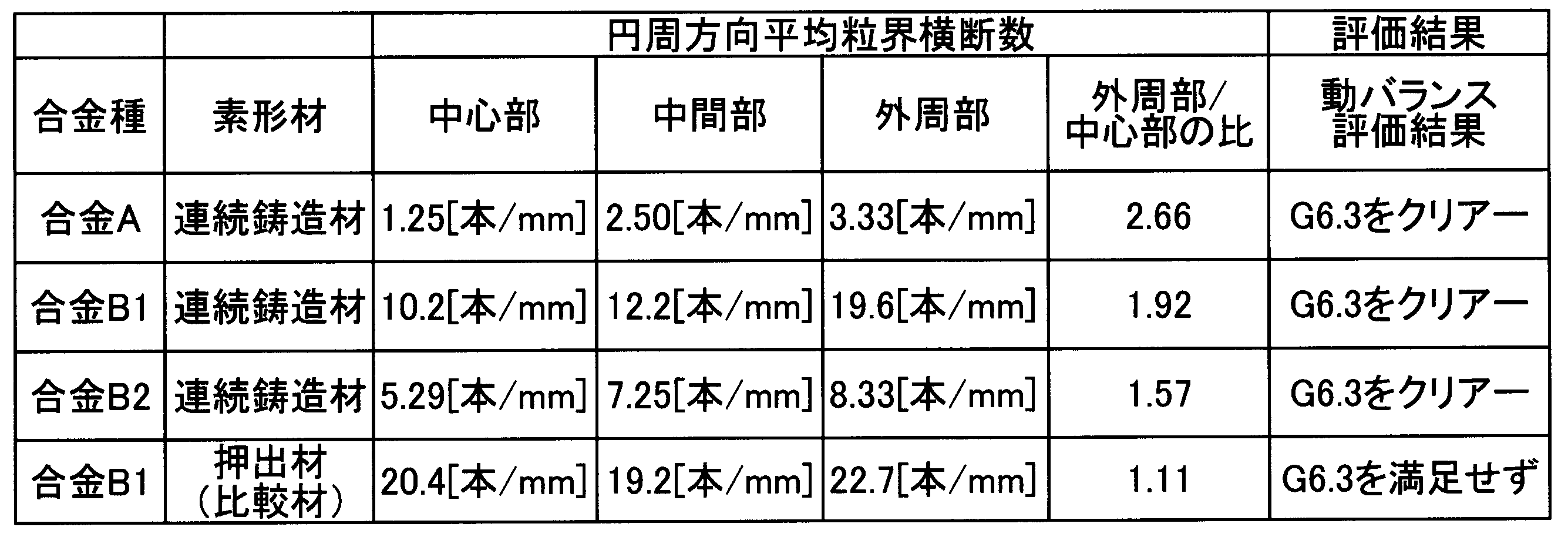
これに対して押出し材を使用した比較例では、円周方向平均粒界横断数の条件が本発明で規定する条件を満たさず(中間部分で最小)、また動バランスの評価結果も、G6.3をクリヤーせず、動バランスが不良であることが判明した。
この実施例2は、細径の連続鋳造棒材を製造し、その細径の連続鋳造棒材を鍛造用素材として、熱間での密閉型鍛造を施し、ターボコンプレッサホイール用素形材とした例である。なおこの例では、鍛造型と鍛造用素材との寸法関係は、図12に示す例(第1の例)、すなわち大径の鍛造用素材を用いた例に倣った。
アルミ地金に添加元素を加えて溶解し、実施例1と同様に、表1に示す合金A(Al-Si共晶系合金)、合金B1(Al-Cu―Mg系合金の2618合金相当)、及び合金B2(Al-Cu―Mg系合金)の各溶湯を、気体加圧式ホットトップ連続鋳造法により、内径φ50mmモールドを使用して鋳造速度300mm/分にて外径49mmの丸棒状に連続鋳造し、連続鋳造棒材を得た。連続鋳造棒材に490℃で12時間保持後に空冷する均質化処理を施し、鋳造肌除去の面削(ピーリング)をして、φ45mmのアルミ合金棒材を得た。この棒材を鋸切断機により切断し、長さ40mmの円柱状の素材(鍛造用素材)を作成した。ここまでは、実施例1と同様である。
上記の素形材に対して、その中央にφ6mmのシャフト穴を機械加工で開け、素形材外周面および両端面を0.7mm切削加工して、動バランス評価用の機械加工品とした。この機械加工品のシャフト穴にφ6.02mmの鉄製シャフト(機械加工仕上げしたシャフト)を圧入した。得られたシャフト付き機械加工品42を、図18に示すように動バランス測定機に取り付け、10000rpmで回転させて、JISB 0905に規定される釣合い良さの等級として、G6.3の等級の条件をクリアーするか否かを調べ、高速回転時の動バランスの評価を行った。
前述のようにして調べた鍛造上がり材からなる素形材についての前記高さ位置での円周方向平均粒界横断数、および動バランス評価結果を、表3に示す。なお、連続鋳造棒材の段階における円周方向平均粒界横断数は、実施例1(表2参照)と同じである。

この実施例3は、実施例2の場合よりも外径が小さい細径の連続鋳造棒材を製造し、その細径の連続鋳造棒材を鍛造用素材として、熱間での密閉型鍛造を施し、ターボコンプレッサホイール用素形材とした例である。なおこの実施例3では、鍛造型と鍛造用素材との寸法関係は、実施例2とは変えて、図15に示す例(第2の例)、すなわち相対的に小径の鍛造用素材を用いた例に倣った。
この円柱形状素材を、420℃に加熱昇温し、図15に示した密閉鍛造金型によりベル型の鍛造素形材に熱間鍛造成形した。この鍛造素形材を495℃に昇温し、2時間保持後に60℃の温水に焼入れし(いわゆる溶体化処理)、続いて200℃に昇温し、8時間保持(いわゆる時効処理)した後、空冷した。なお、円柱状素材(鍛造用素材)の外径と密閉鍛造金型における羽根部最小径側の端部に相当する部位の内径との差(その間の隙間38の幅の2倍)は、0.6mmなるように設定した。
前述のようにして調べた鍛造上がり材からなる素形材についての前記高さ位置での円周方向平均粒界横断数、および動バランス評価結果を、表4に示す。
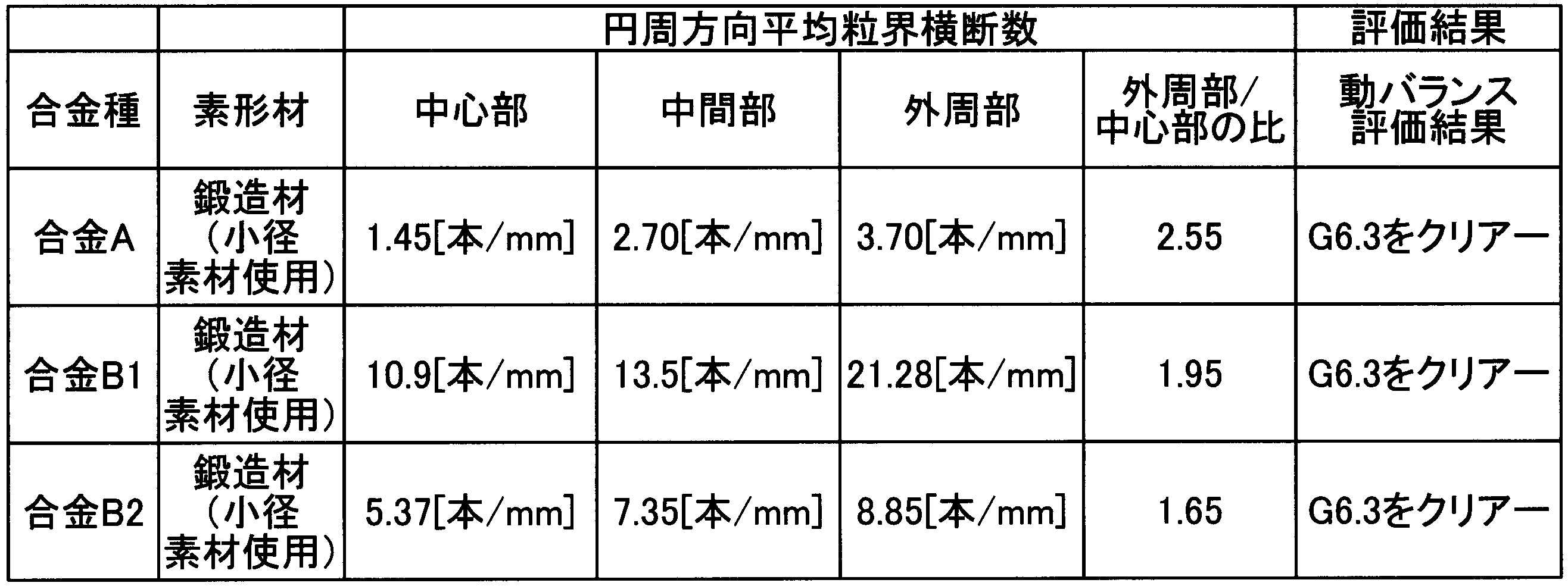
Claims (21)
- 細径の連続鋳造棒材が素材とされ、かつその素材は、鋳造方向に対して直交する横断面で見た円周方向平均粒界横断数が、前記横断面の中心部で最小となり、外周部で最大となる鋳造組織を有し、その素材の鋳造方向がコンプレッサホイールの回転中心軸線方向に沿う、アルミニウム合金製ターボコンプレッサホイール用素形材。
- 請求項1に記載のアルミニウム合金製ターボコンプレッサホイール用素形材において、
前記素材の前記中心部が、最終製品のターボコンプレッサホイールにおいて羽根付け根部となることが予定される部位を含み、前記外周部が、最終製品のターボコンプレッサホイールにおいて前記羽根付け根部より外周側の羽根部となることが予定される部位を含む、アルミニウム合金製ターボコンプレッサホイール用素形材。 - 請求項1、請求項2のいずれかの請求項に記載のアルミニウム合金製ターボコンプレッサホイール用素形材において、
前記素材の連続鋳造棒材が、150mm/分以上の鋳造速度で、外径が25mm以上、120mm以下となるように連続鋳造されたものである、アルミニウム合金製ターボコンプレッサホイール用素形材。 - 細径の連続鋳造棒材からなる素材を、鍛造加圧方向が、素材の鋳造方向に沿いかつコンプレッサホイールの回転中心軸線方向に沿うように、鍛造密閉型鍛造により熱間鍛造した鍛造材からなる、アルミニウム合金製ターボコンプレッサホイール用素形材。
- 請求項4に記載のアルミニウム合金製ターボコンプレッサホイール用素形材において、
前記素材の連続鋳造棒材は、鋳造方向に対して直交する横断面で見た円周方向平均粒界横断数が、中心部で最小となり、外周部で最大となる鋳造組織を有する、アルミニウム合金製ターボコンプレッサホイール用素形材。 - 請求項5に記載のアルミニウム合金製ターボコンプレッサホイール用素形材において、
前記連続鋳造棒材の前記中心部が、最終製品のターボコンプレッサホイールにおいて羽根付け根部となることが予定される部位を含み、前記外周部が、最終製品のターボコンプレッサホイールにおいて前記羽根付け根部より外周側の羽根部となることが予定される部位を含む、アルミニウム合金製ターボコンプレッサホイール用素形材。 - 請求項4~請求項6のいずれかの請求項に記載のアルミニウム合金製ターボコンプレッサホイール用素形材において、
前記素材の連続鋳造棒材が、150mm/分以上の鋳造速度で、外径が25mm以上、120mm以下となるように連続鋳造されたものである、アルミニウム合金製ターボコンプレッサホイール用素形材。 - 請求項4~請求項7のいずれかの請求項に記載のアルミニウム合金製ターボコンプレッサホイール用素形材において、
前記鍛造材が、前記密閉鍛造型の軸方向に沿った方向の全高さの2分の1の位置において、鍛造加圧方向に対して直交する横断面で見た円周方向平均粒界横断数が、中心部で最小となり、外周部で最大となる鍛造組織を有する、アルミニウム合金製ターボコンプレッサホイール用素形材。 - 請求項8に記載のアルミニウム合金製ターボコンプレッサホイール用素形材において、
前記鍛造材の前記中心部が、最終製品のターボコンプレッサホイールにおいて羽根付け根部となることが予定される部位を含み、前記外周部が、最終製品のターボコンプレッサホイールにおいて前記羽根付け根部より外周側の羽根部となることが予定される部位を含む、アルミニウム合金製ターボコンプレッサホイール用素形材。 - 請求項4~請求項9のいずれかの請求項に記載のアルミニウム合金製ターボコンプレッサホイール用素形材において、
前記素材として、その外径が、密閉鍛造型における、コンプレッサホイールの最大径部分に相当する部分の内径、もしくはコンプレッサホイールの羽根部最小径側端部に相当する部分の内径に対して、-2.0mm~-0.10mmの範囲内とされたものが用いられている、アルミニウム合金製ターボコンプレッサホイール用素形材。 - 請求項1~請求項10のいずれかの請求項に記載のアルミニウム合金製ターボコンプレッサホイール用素形材において、
前記アルミニウム合金として、Al-Cu-Mg系合金が用いられている、アルミニウム合金製ターボコンプレッサホイール用素形材。 - 請求項1~請求項10のいずれかの請求項に記載のアルミニウム合金製ターボコンプレッサホイール用素形材において、
前記アルミニウム合金として、Al-Si共晶系合金が用いられている、アルミニウム合金製ターボコンプレッサホイール用素形材。 - アルミニウム合金を細径に連続鋳造して、鋳造方向に対して直交する横断面で見た円周方向平均粒界横断数が、中心部で最小となり、外周部で最大となる鋳造組織を有する細径素材を得る連続鋳造工程と、
前記連続鋳造工程により得られた細径素材を、その鋳造方向がコンプレッサホイールの回転中心軸線方向に沿うようにコンプレッサホイール形状に機械加工する仕上げ加工工程、
とを有してなる、ターボコンプレッサホイールの製造方法。 - 請求項13に記載のターボコンプレッサホイールの製造方法において、
前記連続鋳造工程が、150mm/分以上の鋳造速度で、外径が25mm以上、120mm以下となるように連続鋳造する工程である、ターボコンプレッサホイールの製造方法。 - アルミニウム合金を細径に連続鋳造して、鋳造方向に対して直交する横断面で見た円周方向平均粒界横断数が、中心部で最小となり、外周部で最大となる鋳造組織を有する細径素材を得る連続鋳造工程と、
前記連続鋳造工程により得られた細径素材を、鍛造型に対して、細径素材の中心軸線が、得るべきコンプレッサホイール製品の回転中心軸線に一致するように位置決めして、鍛造加圧方向が細径素材の鋳造方向に沿うように熱間で密閉型鍛造する鍛造工程と、
前記鍛造工程により得られた鍛造材をコンプレッサホイール形状に機械加工する仕上げ加工工程、
とを有してなる、ターボコンプレッサホイールの製造方法。 - 請求項15に記載のターボコンプレッサホイールの製造方法において、
前記鍛造工程に供される細径素材として、その外径が、鍛造型における、得るべきコンプレッサホイール製品の最大外径部分に相当する部分の内径、もしくは得るべきコンプレッサホイール製品ホイールの羽根部最小径側端部に相当する部分の内径に対して、-2.0mm~-0.10mmの範囲内とされているものを用い、
前記鍛造工程において、鍛造型に対する細径素材の位置を、鍛造型における、前記最大径側端部に相当する部分の内周壁、もしくは前記羽根部最小径側端部に相当する部分の内周壁によって位置決めして、細径素材を密閉型鍛造する、ターボコンプレッサホイールの製造方法。 - 請求項15、請求項16のいずれかの請求項に記載のターボコンプレッサホイールの製造方法において、
前記鍛造工程では、切削加工工程によって羽根付け根部とされることが予定されている部位については、塑性加工率を20%未満とし、仕上げ加工工程によって羽根部とされることが予定されている部位の塑性加工率を20%以上とする、ターボコンプレッサホイールの製造方法。 - 請求項15~請求項17のいずれかの請求項に記載のターボコンプレッサホイールの製造方法において、
前記鍛造工程によって、前記密閉鍛造型の軸方向に沿った方向の全高さの2分の1の位置において、鍛造加圧方向に対して直交する横断面で見た円周方向平均粒界横断数が、中心部で最小となり、外周部で最大となる鍛造組織を有する鍛造材を得る、ターボコンプレッサホイールの製造方法。 - 請求項15~請求項18のいずれかの請求項に記載のターボコンプレッサホイールの製造方法において、
前記鍛造工程の後、仕上げ加工工程の前に、熱処理工程として、溶体化処理と、その安定化処理後の人工時効硬化処理もしくは安定化処理とを施す、ターボコンプレッサホイールの製造方法。 - 請求項13~19のうちのいずれかの請求項に記載のターボコンプレッサホイールの製造方法において、
前記アルミニウム合金として、Al-Cu-Mg系合金を用いる、ターボコンプレッサホイールの製造方法。 - 請求項13~19のうちのいずれかの請求項に記載のターボコンプレッサホイールの製造方法において、
前記アルミニウム合金として、Al-Si共晶系合金を用いる、ターボコンプレッサホイールの製造方法。
Priority Applications (3)
| Application Number | Priority Date | Filing Date | Title |
|---|---|---|---|
| US15/102,585 US10253782B2 (en) | 2013-12-13 | 2014-12-10 | Shaped component for aluminum alloy turbo compressor wheel and method of manufacturing turbo compressor wheel |
| JP2015552479A JP6478412B2 (ja) | 2013-12-13 | 2014-12-10 | アルミニウム合金製ターボコンプレッサホイール用素形材およびターボコンプレッサホイールの製造方法 |
| DE112014005623.5T DE112014005623T5 (de) | 2013-12-13 | 2014-12-10 | Geformtes Bauteil aus Aluminium für ein Turbokompressorrad und Verfahren zum Herstellen eines Turbokompressorrades |
Applications Claiming Priority (2)
| Application Number | Priority Date | Filing Date | Title |
|---|---|---|---|
| JP2013258638 | 2013-12-13 | ||
| JP2013-258638 | 2013-12-13 |
Publications (1)
| Publication Number | Publication Date |
|---|---|
| WO2015087907A1 true WO2015087907A1 (ja) | 2015-06-18 |
Family
ID=53371208
Family Applications (1)
| Application Number | Title | Priority Date | Filing Date |
|---|---|---|---|
| PCT/JP2014/082663 Ceased WO2015087907A1 (ja) | 2013-12-13 | 2014-12-10 | アルミニウム合金製ターボコンプレッサホイール用素形材およびターボコンプレッサホイールの製造方法 |
Country Status (4)
| Country | Link |
|---|---|
| US (1) | US10253782B2 (ja) |
| JP (1) | JP6478412B2 (ja) |
| DE (1) | DE112014005623T5 (ja) |
| WO (1) | WO2015087907A1 (ja) |
Cited By (7)
| Publication number | Priority date | Publication date | Assignee | Title |
|---|---|---|---|---|
| JP2017030030A (ja) * | 2015-08-05 | 2017-02-09 | 株式会社Uacj鋳鍛 | 回転体用鍛造材及びそれを用いた回転体の製造方法 |
| JP2017111409A (ja) * | 2015-12-18 | 2017-06-22 | 富士ゼロックス株式会社 | 導電性支持体、電子写真感光体、プロセスカートリッジ、画像形成装置、及び導電性支持体の製造方法 |
| JP2019190366A (ja) * | 2018-04-25 | 2019-10-31 | 昭和電工株式会社 | インペラ用鍛造品 |
| JP2019190364A (ja) * | 2018-04-25 | 2019-10-31 | 昭和電工株式会社 | インペラ用鍛造品 |
| JP2019190365A (ja) * | 2018-04-25 | 2019-10-31 | 昭和電工株式会社 | インペラ用鍛造品 |
| JP2020012182A (ja) * | 2018-07-20 | 2020-01-23 | 日本軽金属株式会社 | インペラ用冷間鍛造材及びその製造方法 |
| CN115091145A (zh) * | 2022-07-29 | 2022-09-23 | 重庆江增船舶重工有限公司 | 一种增压器铸造涡轮加工方法 |
Families Citing this family (11)
| Publication number | Priority date | Publication date | Assignee | Title |
|---|---|---|---|---|
| US20160102554A1 (en) * | 2014-10-08 | 2016-04-14 | Caterpillar Inc. | Inspection and qualification for remanufacturing of compressor wheels |
| US10060350B2 (en) * | 2015-04-13 | 2018-08-28 | United Technologies Corporation | Nose cone assembly and method of circulating air in a gas turbine engine |
| US10215096B2 (en) * | 2015-11-04 | 2019-02-26 | United Technologies Corporation | Engine with nose cone heat exchanger and radially outer discharge |
| US10772654B2 (en) | 2017-03-02 | 2020-09-15 | Covidien Lp | Fluid-driven tissue resecting instruments, systems, and methods |
| US10393134B2 (en) * | 2017-08-04 | 2019-08-27 | Borgwarner Inc. | Polymeric compressor wheel with metal sleeve |
| WO2019087281A1 (ja) * | 2017-10-31 | 2019-05-09 | 三菱重工エンジン&ターボチャージャ株式会社 | タービン動翼、ターボチャージャ及びタービン動翼の製造方法 |
| US11661951B2 (en) * | 2020-03-13 | 2023-05-30 | Turbonetics Holdings, Inc. | Methods and systems for manufacturing an impeller wheel assembly |
| USD1044870S1 (en) * | 2022-02-14 | 2024-10-01 | Fizzle Llc | Compressor wheel |
| USD1048108S1 (en) * | 2022-02-14 | 2024-10-22 | Fizzle Llc | Compressor wheel |
| US12221976B1 (en) * | 2023-08-07 | 2025-02-11 | Hamilton Sundstrand Corporation | Radial impeller with maximized inducer area |
| CN119187463B (zh) * | 2024-10-30 | 2025-08-19 | 扬州市江都区飞跃泵业有限公司 | 一种双叶片半开式污水泵叶轮及其制造装置、方法 |
Citations (5)
| Publication number | Priority date | Publication date | Assignee | Title |
|---|---|---|---|---|
| JPH11170014A (ja) * | 1997-12-03 | 1999-06-29 | Kobe Steel Ltd | 横型連続鋳造装置 |
| JP2000197943A (ja) * | 1998-12-28 | 2000-07-18 | Furukawa Electric Co Ltd:The | 鍛造品回転体及びその製造方法 |
| JP2006305629A (ja) * | 2005-03-30 | 2006-11-09 | Kobe Steel Ltd | 回転体用鍛造材の製造方法 |
| JP2008132513A (ja) * | 2006-11-28 | 2008-06-12 | Showa Denko Kk | 鍛造加工方法 |
| JP2009066601A (ja) * | 2007-09-10 | 2009-04-02 | Showa Denko Kk | ロータ素材鍛造用金型およびロータ素材の鍛造方法 |
Family Cites Families (9)
| Publication number | Priority date | Publication date | Assignee | Title |
|---|---|---|---|---|
| JP3513281B2 (ja) * | 1995-08-17 | 2004-03-31 | ヤンマー株式会社 | 耐圧・高強度アルミニウムの鋳造法 |
| US6663347B2 (en) * | 2001-06-06 | 2003-12-16 | Borgwarner, Inc. | Cast titanium compressor wheel |
| JP4290024B2 (ja) * | 2004-01-26 | 2009-07-01 | 古河スカイ株式会社 | 耐熱強度に優れたターボチャージャー用アルミニウム合金鋳物製コンプレッサーインペラー |
| WO2008001758A1 (en) * | 2006-06-29 | 2008-01-03 | Hitachi Metals Precision, Ltd. | Casting aluminum alloy, cast compressor impeller comprising the alloy, and process for producing the same |
| JP5048996B2 (ja) * | 2006-11-10 | 2012-10-17 | 昭和電工株式会社 | 加工性に優れた耐摩耗性アルミニウム合金材およびその製造方法 |
| CA2776003C (en) * | 2012-04-27 | 2019-03-12 | Rio Tinto Alcan International Limited | Aluminum alloy having an excellent combination of strength, extrudability and corrosion resistance |
| US10018203B2 (en) * | 2012-10-26 | 2018-07-10 | Uacj Corporation | Al alloy cast impeller for compressor and process for producing same |
| JP2017503086A (ja) * | 2013-12-13 | 2017-01-26 | リオ ティント アルカン インターナショナル リミテッドRio Tinto Alcan International Limited | 改善された高温性能を有するアルミニウム鋳造合金 |
| WO2015141191A1 (ja) * | 2014-03-15 | 2015-09-24 | 株式会社Uacj | Al合金鋳物製コンプレッサーインペラー及びその製造方法 |
-
2014
- 2014-12-10 JP JP2015552479A patent/JP6478412B2/ja active Active
- 2014-12-10 WO PCT/JP2014/082663 patent/WO2015087907A1/ja not_active Ceased
- 2014-12-10 DE DE112014005623.5T patent/DE112014005623T5/de not_active Withdrawn
- 2014-12-10 US US15/102,585 patent/US10253782B2/en not_active Expired - Fee Related
Patent Citations (5)
| Publication number | Priority date | Publication date | Assignee | Title |
|---|---|---|---|---|
| JPH11170014A (ja) * | 1997-12-03 | 1999-06-29 | Kobe Steel Ltd | 横型連続鋳造装置 |
| JP2000197943A (ja) * | 1998-12-28 | 2000-07-18 | Furukawa Electric Co Ltd:The | 鍛造品回転体及びその製造方法 |
| JP2006305629A (ja) * | 2005-03-30 | 2006-11-09 | Kobe Steel Ltd | 回転体用鍛造材の製造方法 |
| JP2008132513A (ja) * | 2006-11-28 | 2008-06-12 | Showa Denko Kk | 鍛造加工方法 |
| JP2009066601A (ja) * | 2007-09-10 | 2009-04-02 | Showa Denko Kk | ロータ素材鍛造用金型およびロータ素材の鍛造方法 |
Cited By (8)
| Publication number | Priority date | Publication date | Assignee | Title |
|---|---|---|---|---|
| JP2017030030A (ja) * | 2015-08-05 | 2017-02-09 | 株式会社Uacj鋳鍛 | 回転体用鍛造材及びそれを用いた回転体の製造方法 |
| JP2017111409A (ja) * | 2015-12-18 | 2017-06-22 | 富士ゼロックス株式会社 | 導電性支持体、電子写真感光体、プロセスカートリッジ、画像形成装置、及び導電性支持体の製造方法 |
| JP2019190366A (ja) * | 2018-04-25 | 2019-10-31 | 昭和電工株式会社 | インペラ用鍛造品 |
| JP2019190364A (ja) * | 2018-04-25 | 2019-10-31 | 昭和電工株式会社 | インペラ用鍛造品 |
| JP2019190365A (ja) * | 2018-04-25 | 2019-10-31 | 昭和電工株式会社 | インペラ用鍛造品 |
| JP2020012182A (ja) * | 2018-07-20 | 2020-01-23 | 日本軽金属株式会社 | インペラ用冷間鍛造材及びその製造方法 |
| JP7131160B2 (ja) | 2018-07-20 | 2022-09-06 | 日本軽金属株式会社 | インペラ用冷間鍛造材及びその製造方法 |
| CN115091145A (zh) * | 2022-07-29 | 2022-09-23 | 重庆江增船舶重工有限公司 | 一种增压器铸造涡轮加工方法 |
Also Published As
| Publication number | Publication date |
|---|---|
| JP6478412B2 (ja) | 2019-03-06 |
| DE112014005623T5 (de) | 2016-09-22 |
| US10253782B2 (en) | 2019-04-09 |
| US20160312787A1 (en) | 2016-10-27 |
| JPWO2015087907A1 (ja) | 2017-03-16 |
Similar Documents
| Publication | Publication Date | Title |
|---|---|---|
| JP6478412B2 (ja) | アルミニウム合金製ターボコンプレッサホイール用素形材およびターボコンプレッサホイールの製造方法 | |
| KR101356243B1 (ko) | 브레이크 피스톤의 제조 방법 | |
| TWI467036B (zh) | 銅合金熱鍛件 | |
| JP5830006B2 (ja) | 強度に優れたアルミニウム合金押出材 | |
| JP5756091B2 (ja) | アルミニウム合金鍛造部材の製造方法 | |
| CN111532080B (zh) | 铝合金锻造车轮及其制造方法、锻造车轮形成用铸坯 | |
| JPWO2008001758A1 (ja) | アルミニウム鋳造合金、この合金から成る鋳造コンプレッサ羽根車およびその製造方法 | |
| WO2017033663A1 (ja) | アルミニウム合金押出材及びその製造方法 | |
| JP2017503086A (ja) | 改善された高温性能を有するアルミニウム鋳造合金 | |
| JP2008121057A (ja) | 加工性に優れた耐摩耗性アルミニウム合金材およびその製造方法 | |
| JP4958292B2 (ja) | アルミニウムダイカスト合金、この合金からなる鋳造コンプレッサ羽根車およびその製造方法 | |
| JP6395305B2 (ja) | アルミニウム合金製ターボコンプレッサホイール用鍛造素形材およびその製造方法 | |
| JP6718219B2 (ja) | 耐熱性アルミニウム合金材の製造方法 | |
| WO2020031579A1 (ja) | Ni基超耐熱合金の製造方法およびNi基超耐熱合金 | |
| JP2001020047A (ja) | アルミニウム合金鍛造用素材およびその製造方法 | |
| JP6829782B2 (ja) | 耐熱性アルミニウム合金材の製造方法 | |
| JP2019210502A (ja) | プリフォーム及びTiAl系タービンホイールの製造方法 | |
| KR20170027316A (ko) | 절삭성이 우수한 알루미늄 합금 압출재 및 그의 제조 방법 | |
| JP7131160B2 (ja) | インペラ用冷間鍛造材及びその製造方法 | |
| JP6829783B2 (ja) | 耐熱性アルミニウム合金材の製造方法 | |
| JP4845201B2 (ja) | アルミニウムダイカスト合金およびこれを用いたコンプレッサ羽根車 | |
| JP6875795B2 (ja) | 内燃機関用ピストン及びその製造方法 | |
| JP7131161B2 (ja) | インペラ用押出材及びその製造方法 | |
| JP2005330560A (ja) | アルミニウム合金、棒状材、鍛造成形品、機械加工成形品、それを用いた陽極酸化皮膜硬さに優れた耐摩耗性アルミニウム合金、摺動部品、及びそれらの製造方法 | |
| JP2008088460A (ja) | 高強度アルミニウム鋳造合金およびこれを用いたコンプレッサ羽根車 |
Legal Events
| Date | Code | Title | Description |
|---|---|---|---|
| 121 | Ep: the epo has been informed by wipo that ep was designated in this application |
Ref document number: 14868903 Country of ref document: EP Kind code of ref document: A1 |
|
| ENP | Entry into the national phase |
Ref document number: 2015552479 Country of ref document: JP Kind code of ref document: A |
|
| WWE | Wipo information: entry into national phase |
Ref document number: 15102585 Country of ref document: US |
|
| WWE | Wipo information: entry into national phase |
Ref document number: 112014005623 Country of ref document: DE |
|
| 122 | Ep: pct application non-entry in european phase |
Ref document number: 14868903 Country of ref document: EP Kind code of ref document: A1 |