WO2015083283A1 - 駆動装置、電子機器、駆動制御プログラム、及び駆動信号の生成方法 - Google Patents
駆動装置、電子機器、駆動制御プログラム、及び駆動信号の生成方法 Download PDFInfo
- Publication number
- WO2015083283A1 WO2015083283A1 PCT/JP2013/082803 JP2013082803W WO2015083283A1 WO 2015083283 A1 WO2015083283 A1 WO 2015083283A1 JP 2013082803 W JP2013082803 W JP 2013082803W WO 2015083283 A1 WO2015083283 A1 WO 2015083283A1
- Authority
- WO
- WIPO (PCT)
- Prior art keywords
- frequency
- vibration
- drive signal
- lra
- generating device
- Prior art date
- Legal status (The legal status is an assumption and is not a legal conclusion. Google has not performed a legal analysis and makes no representation as to the accuracy of the status listed.)
- Ceased
Links
Images












Classifications
-
- G—PHYSICS
- G06—COMPUTING OR CALCULATING; COUNTING
- G06F—ELECTRIC DIGITAL DATA PROCESSING
- G06F3/00—Input arrangements for transferring data to be processed into a form capable of being handled by the computer; Output arrangements for transferring data from processing unit to output unit, e.g. interface arrangements
- G06F3/01—Input arrangements or combined input and output arrangements for interaction between user and computer
- G06F3/016—Input arrangements with force or tactile feedback as computer generated output to the user
-
- B—PERFORMING OPERATIONS; TRANSPORTING
- B06—GENERATING OR TRANSMITTING MECHANICAL VIBRATIONS IN GENERAL
- B06B—METHODS OR APPARATUS FOR GENERATING OR TRANSMITTING MECHANICAL VIBRATIONS OF INFRASONIC, SONIC, OR ULTRASONIC FREQUENCY, e.g. FOR PERFORMING MECHANICAL WORK IN GENERAL
- B06B1/00—Methods or apparatus for generating mechanical vibrations of infrasonic, sonic, or ultrasonic frequency
- B06B1/02—Methods or apparatus for generating mechanical vibrations of infrasonic, sonic, or ultrasonic frequency making use of electrical energy
- B06B1/04—Methods or apparatus for generating mechanical vibrations of infrasonic, sonic, or ultrasonic frequency making use of electrical energy operating with electromagnetism
- B06B1/045—Methods or apparatus for generating mechanical vibrations of infrasonic, sonic, or ultrasonic frequency making use of electrical energy operating with electromagnetism using vibrating magnet, armature or coil system
-
- B—PERFORMING OPERATIONS; TRANSPORTING
- B06—GENERATING OR TRANSMITTING MECHANICAL VIBRATIONS IN GENERAL
- B06B—METHODS OR APPARATUS FOR GENERATING OR TRANSMITTING MECHANICAL VIBRATIONS OF INFRASONIC, SONIC, OR ULTRASONIC FREQUENCY, e.g. FOR PERFORMING MECHANICAL WORK IN GENERAL
- B06B1/00—Methods or apparatus for generating mechanical vibrations of infrasonic, sonic, or ultrasonic frequency
- B06B1/02—Methods or apparatus for generating mechanical vibrations of infrasonic, sonic, or ultrasonic frequency making use of electrical energy
- B06B1/06—Methods or apparatus for generating mechanical vibrations of infrasonic, sonic, or ultrasonic frequency making use of electrical energy operating with piezoelectric effect or with electrostriction
-
- G—PHYSICS
- G06—COMPUTING OR CALCULATING; COUNTING
- G06F—ELECTRIC DIGITAL DATA PROCESSING
- G06F3/00—Input arrangements for transferring data to be processed into a form capable of being handled by the computer; Output arrangements for transferring data from processing unit to output unit, e.g. interface arrangements
- G06F3/01—Input arrangements or combined input and output arrangements for interaction between user and computer
- G06F3/03—Arrangements for converting the position or the displacement of a member into a coded form
- G06F3/041—Digitisers, e.g. for touch screens or touch pads, characterised by the transducing means
-
- H—ELECTRICITY
- H02—GENERATION; CONVERSION OR DISTRIBUTION OF ELECTRIC POWER
- H02P—CONTROL OR REGULATION OF ELECTRIC MOTORS, ELECTRIC GENERATORS OR DYNAMO-ELECTRIC CONVERTERS; CONTROLLING TRANSFORMERS, REACTORS OR CHOKE COILS
- H02P25/00—Arrangements or methods for the control of AC motors characterised by the kind of AC motor or by structural details
- H02P25/02—Arrangements or methods for the control of AC motors characterised by the kind of AC motor or by structural details characterised by the kind of motor
- H02P25/032—Reciprocating, oscillating or vibrating motors
Definitions
- the present invention relates to a drive device, an electronic device, a drive control program, and a drive signal generation method for driving a vibration generating device.
- a user comprising a panel having a surface and capable of supporting flexural waves, a touch-sensitive input device associated with the surface, and means including a force transducer for providing force feedback to the input device /
- the force is in the form of a pulse on the panel, the pulse is in the form of a modulated signal that provides a button click sensation to the user's fingertip, and the modulated signal has a fundamental carrier frequency in the range of 150-750 Hz. And has a duration of at least 10 ms (see, for example, Patent Document 1).
- the drive device is a vibration generation device having a resonance frequency rated value of f0, wherein the resonance frequency includes the rated value f0 according to an acceleration amplitude from the first resonance frequency f11 to the second resonance frequency.
- a first drive signal that vibrates the vibration generator m times, or a frequency f1 (m / n) ⁇ q (t) (m and n are positive numbers different from each other).
- a storage unit storing waveform data representing a second drive signal that vibrates the vibration generator (m / 2) ⁇ a (a is a natural number other than 0) times.
- Reading the waveform data stored in the storage unit A drive processing unit that outputs the first drive signal or the second drive signal corresponding to the waveform data to the vibration generating device, and the time characteristic q (t) has the resonance frequency in consideration of an error.
- a third drive signal or a sine wave satisfying the frequency f1 (m / n) ⁇ f2 (m and n are different positive odd numbers), and the vibration generating device is (m / 2) ⁇ a (a Is a time characteristic obtained when the vibration generating device is driven by a fourth drive signal that is vibrated a number of times, and the resonance frequency of the vibration generating device changes with time.
- the resonance frequency of the vibration generating device changes according to the acceleration amplitude, it is possible to provide a tactile sensation according to the operation.
- FIG. 5 is a diagram for describing an overview of Embodiment 1.
- FIG. It is a figure which shows the sensitivity of a human acceleration organ.
- 6 is a diagram illustrating an electronic device of Embodiment 1.
- FIG. It is a figure which shows the example of LRA.
- FIG. 4 is a flowchart for explaining LRA driving by the driving apparatus according to the first embodiment;
- It is a figure which shows the example of the schematic diagram of LRA.
- 6 is a diagram illustrating an example of an LRA drive signal according to Embodiment 1.
- FIG. It is a figure explaining the displacement of LRA. It is a figure which shows the example of the speed of vibration of LRA, and the acceleration of a vibration.
- FIG. It is a figure which shows the displacement, speed, and acceleration of free vibration, forced vibration, and response vibration when forced vibration Jsinpt is applied to the object 301.
- FIG. It is a figure which shows the displacement, speed, and acceleration of free vibration, forced vibration, and response vibration when object 301 is vibrated (m / 2) ⁇ a times at frequency f1 when n and m are both odd numbers.
- FIG. 3 is a diagram (part 1) illustrating a method for generating a drive signal of LRA 140 according to the first embodiment in a stepwise manner.
- FIG. 3 is a diagram (part 2) illustrating a method for generating a drive signal of LRA 140 according to the first embodiment in a stepwise manner.
- FIG. 4 is a diagram (part 3) illustrating a method for generating a drive signal of LRA 140 according to the first embodiment in a stepwise manner; It is a figure explaining the drive device of Embodiment 2.
- FIG. 10 is a flowchart for explaining a resonance frequency measurement process in the second embodiment.
- FIG. 1 is a diagram for explaining the outline of the first embodiment.
- FIG. 1A is a diagram showing a waveform 11 of acceleration of vibration generated when the accelerometer 1 is attached to a human finger and the button 2 is pressed.
- FIG. 1B is a diagram illustrating a waveform 12 of acceleration of vibration generated when the accelerometer 1 is attached to a human finger and a touch panel 3 to which an LRA (Linear Resonant Actuator) is attached is touched.
- the button 2 is, for example, a metal dome type button.
- the button 2 and the touch panel 3 are provided on the electronic device.
- the vibration indicated by waveform 11 is rapidly damped in one to several cycles.
- the vibration indicated by the waveform 12 continues until the free vibration due to the natural frequency of the LRA is attenuated even after the supply of the drive signal is stopped.
- the free vibration due to the natural frequency of the LRA that continues even after the supply of the drive signal is stopped is referred to as residual vibration.
- FIG. 2 is a diagram showing the sensitivity of the human acceleration organ.
- An organ that senses human acceleration is a Pachiny body. Patini bodies are one of the four major mechanoreceptors found primarily in the skin.
- the finger since the acceleration of the vibration is 0.02 G or less within 0.01 sec, the finger does not sense the vibration.
- waveform 12 0.1 sec is required until the acceleration of vibration becomes 0.02 G or less, and the finger continues to sense vibration until 0.1 sec elapses. Therefore, the vibration indicated by the waveform 11 and the vibration indicated by the waveform 12 are completely different as tactile sensations that humans sense.
- FIG. 3 is a diagram illustrating the electronic device according to the first embodiment.
- the electronic device of the first embodiment may be a device having, for example, a touch panel having a display function and an input function as input means.
- the electronic device according to the first embodiment may be a smartphone, a tablet computer, a portable information terminal, or the like.
- the electronic device 100 includes a housing 110, a touch panel 120, a double-sided tape 130, an LRA 140, and a substrate 150.
- the touch panel 120 is fixed to the housing 110 by the double-sided tape 130.
- the LRA 140 is attached to the surface of the touch panel 120 on the housing side.
- the LRA 140 is a vibration generation device that generates vibration by driving at a resonance frequency mainly by combining a vibration system having a resonance frequency designed in advance and an actuator. The amount of vibration changes depending on the amplitude of the drive waveform. To do. Details of the LRA 140 will be described later.
- the LRA 140 is a vibration generating device.
- the LRA 140 is not limited to the LRA as long as it has a resonator and an actuator for excitation.
- the substrate 150 is disposed inside the housing 110.
- a driver IC that outputs a driving signal to the LRA 140 is mounted on the substrate 150 in order to control driving of the LRA 140.
- the electronic device 100 When the user's finger contacts the touch panel 120, the electronic device 100 according to the first embodiment senses this contact, drives the LRA 140 by the driving device mounted on the substrate 150, and propagates the vibration of the LRA 140 to the touch panel 120.
- the electronic device 100 may be any device that uses the touch panel 120 as an input operation unit, and is a device that is installed and used in a specific location, such as ATM (Automatic Teller Machine). Also good.
- ATM Automatic Teller Machine
- FIG. 4 is a diagram illustrating an example of LRA.
- FIG. 4A is a diagram showing an example of LRA using a voice coil
- FIG. 4B is a diagram showing an example of LRA using a piezoelectric element.
- the 4A includes a spring 31, a magnet 32, and a coil 33.
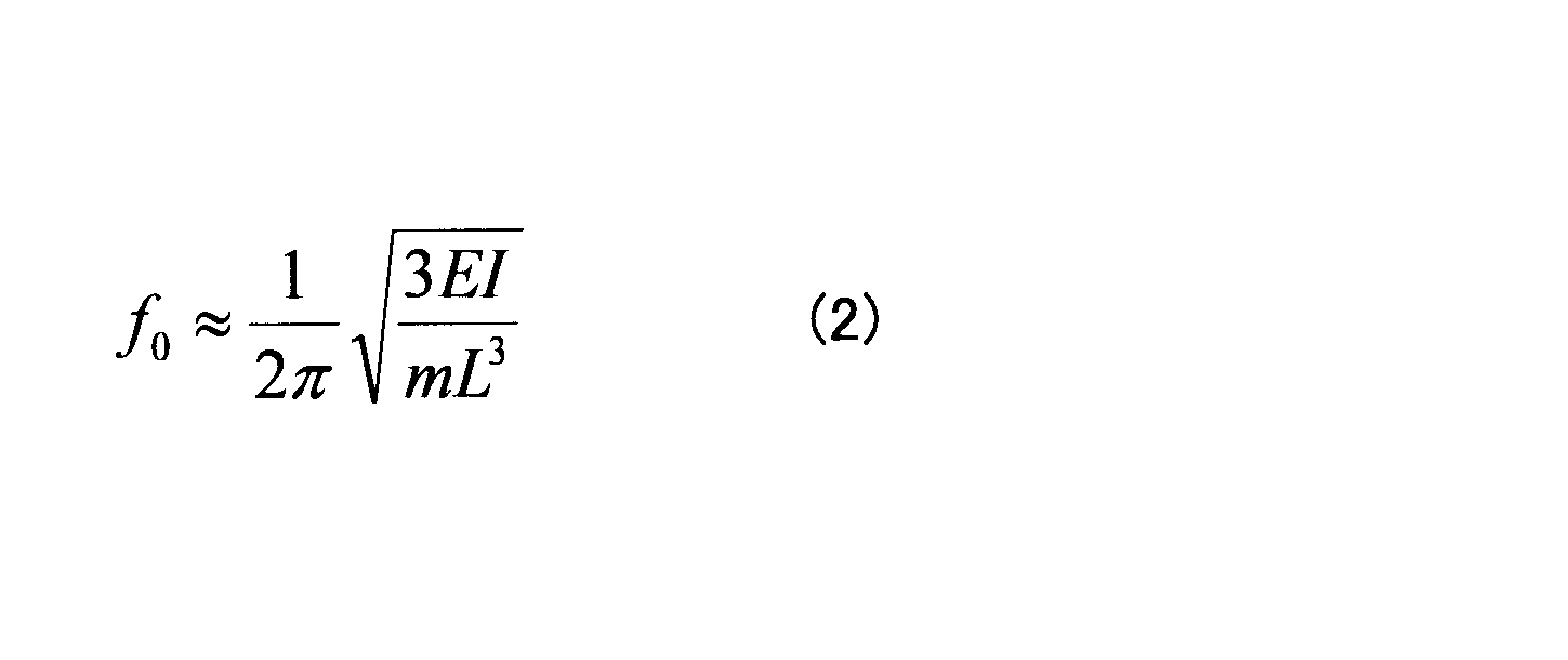
- An LRA 40 illustrated in FIG. 4B includes a weight 41, a beam 42, and a piezoelectric element 43.
- the mass of the weight 41 is m
- the Young's modulus of the beam 42 is E
- the sectional moment of the beam 42 is I
- L is the length of the beam 42 in the longitudinal direction
- the natural frequency f0 is as follows. It is shown by Formula (2).
- the LRA 30 using a voice coil may be applied, or the LRA 40 using the piezoelectric element 43 may be applied.
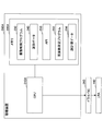
- FIG. 5 is a diagram illustrating the driving device according to the first embodiment.
- the driving apparatus 200 includes a CPU (Central Processing Unit) 210 and a memory 220.
- the CPU 210 reads and executes the drive control program 230 stored in the memory 220, thereby performing drive processing of the LRA 140 described later.
- the memory 220 stores a storage area in which a drive control program 230 for controlling the drive of the LRA 140 is stored, a storage area in which waveform data 240 is stored, and an API (Application Programming Interface) 250 that provides tactile sensation. And an area.
- the drive control program 230 causes the CPU 210 to execute drive control of the LRA 140.
- the waveform data 240 is drive waveform data generated in advance in order to express a click feeling by vibration generated by the LRA 140. Details of the waveform data 240 will be described later.
- the API 250 is activated by the drive control program 230 and performs various processes for providing a tactile sensation. In FIG. 5, the API 250 is stored in the memory 220 in FIG. 5, but may be stored in another memory mounted on the board 150.
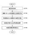
- FIG. 6 is a flowchart for explaining driving of the LRA 140 by the driving apparatus according to the first embodiment.
- the driving device 200 activates the API 250 (step S602) when detecting contact with the touch panel 120 (step S601). Specifically, the driving device 200 may activate the API 250 when, for example, there is a touch on a button displayed on the touch panel 120.
- the API 250 reads the waveform data 240 stored in the memory 220 and outputs a drive command corresponding to the waveform data 240 to the driver IC 260 (step S603).
- the driver IC 260 performs D / A (Digital-to-Analog) conversion on the waveform data 240 (step S604), and amplifies it with an amplifier or the like (step S605).
- the driver IC 260 outputs the amplified signal to the LRA 140 (step S606).
- the waveform data 240 of the first embodiment is data indicating the waveform of the drive signal that satisfies a specific condition for stopping the residual vibration.
- the LRA 140 is vibrated m times with a signal having a frequency f1.
- FIG. 7 is a diagram illustrating an example of a schematic diagram of the LRA 140 according to the first embodiment
- FIG. 8 is a diagram illustrating an example of a drive signal of the LRA 140 according to the first embodiment.
- data indicating the drive signal Z shown in FIG. 8 is stored in the memory 220 as the waveform data 240.
- the waveform data 240 may include, for example, the value of the frequency f1 of the drive signal Z, the values of amplitude and phase, the values of m and n, and the like.
- the waveform data 240 may be data indicating the waveform of the drive signal Z itself.
- the frequency f1 of the drive signal Z is preferably set so that the error is 1% or less with respect to m / n ⁇ f0. If the frequency f1 is set in this way, even if residual vibration occurs after the application of the drive signal is stopped, the acceleration of the vibration is 0.02G or less, which is the human detection lower limit, and is not perceived by humans. There is no loss.
- step S603 in FIG. 6 the driving apparatus 200 according to the first embodiment reads the waveform data 240 indicating the driving signal Z by the API 250, and outputs a driving command corresponding to the waveform data 240 to the driver IC 260.
- the driver IC 260 D / A converts and amplifies the waveform data 240 and outputs it to the LRA 140.
- FIG. 9 is a diagram for explaining the displacement of the LRA.
- FIG. 9A is a first diagram for explaining the displacement
- FIG. 9B is a second diagram for explaining the displacement.
- the waveform indicated by the dotted line indicates the forced vibration component y1 of the vibration displacement generated when the drive signal Z is applied to the LRA 140
- the waveform indicated by the solid line indicates the free vibration component y2.
- the response displacement y3 when the drive signal Z is applied to the LRA 140 is a composite wave of the forced vibration component y1 and the free vibration component y2.
- FIG. 9B is a diagram showing an example of the response displacement y3. It can be seen that the response displacement y3 becomes 0 at the timing T when the drive signal Z becomes 0.
- FIG. 10 is a diagram illustrating an example of the vibration speed and vibration acceleration of the LRA 140.
- 10A is a diagram showing a waveform of the response displacement y3
- FIG. 10B is a diagram showing a waveform of a velocity waveform y3 ′ which is a derivative of the response displacement y3
- FIG. 10C is a response. It is a figure which shows the waveform of the waveform y3 "of the acceleration which is a 2nd derivative of the displacement y3.
- the velocity waveform y3 ′ and the acceleration waveform y3 ′′ become 0 when the response displacement y3 becomes 0. That is, the vibration of the LRA 140 stops at the timing T.
- the acceleration waveform y3 ′′ stops in two cycles within 0.01 sec. Therefore, in the example of FIG. 10, when the acceleration of vibration becomes 0.02 G or less within 0.01 sec and the button 2 is clicked. A feeling can be expressed.
- the present invention is not limited to this.
- m and n need only satisfy natural numbers (not including 0) and m ⁇ n.
- the relationship between m and n is preferably a relationship satisfying m> n.
- FIG. 11 is a diagram illustrating vibration acceleration of the LRA 140 when a sine wave having a resonance frequency of the LRA 140 is used as a drive signal.
- FIG. 11B shows the acceleration of vibration of the LRA 140 when a simulation is performed using the sine wave of FIG. 11A as a drive signal.
- the acceleration of the touch panel 120 is detected by placing an accelerometer in the center of the touch panel 120.
- FIG. 12 is a diagram showing acceleration of vibration of the LRA 140 when a voltage having a phase opposite to that of the vibration generated in the LRA 140 by a drive command is added as a vibration suppression signal.
- FIG. 12B shows the touch panel 120 when the sine wave of FIG. 12A is used as a drive signal in an actual machine equipped with the LRA 140, and a voltage having a phase opposite to the vibration generated in the LRA 140 after the supply of the drive signal is stopped. The acceleration of vibration is shown.
- the residual vibration is smaller than that of FIG. 11, but it takes 0.05 sec or more before the acceleration of vibration becomes 0.02 G or less of the human detection lower limit.
- FIG. 13 is a diagram illustrating vibration acceleration of the LRA 140 when a signal that does not satisfy a specific condition is used as a drive signal.
- FIG. 13A shows a sinusoidal drive signal having a frequency of 300 Hz that does not satisfy a specific condition.
- FIG. 13B shows acceleration of vibration of the LRA 140 when a simulation is performed using the sine wave of FIG. 13A as a drive signal.
- FIG. 14 is a diagram showing the acceleration of vibration of the LRA 140 when a signal satisfying a specific condition is used as a drive signal.
- FIG. 14A shows a sinusoidal drive signal having a frequency of 350 Hz that satisfies a specific condition.
- FIG. 14B shows the acceleration of vibration of the LRA 140 when a simulation is performed using the sine wave of FIG. 14A as a drive signal.
- the acceleration of the residual vibration is 0.02 G or less of the detection lower limit, and the vibration waveform is a short-time waveform.
- the vibration acceleration waveform of the touch panel 120 in an actual machine equipped with the LRA 140 is a short-time waveform that rapidly attenuates in one to several cycles, and can express a click feeling.
- FIG. 15 is a diagram illustrating a vibration system 300 including an object 301 and a spring 302.
- the mass of the object 301 is M, and the object 301 is connected to the lower end of the spring 302.
- the spring constant of the spring 302 is K.
- the upper end of the spring 302 is a fixed end, and the lower end of the spring 302 is a free end.
- the position of the object 301 (the balance position) in a state where the object 301 is suspended from the spring 302 without applying a force to the object 301 is the origin, and the displacement of the object 301 with respect to the origin is represented by x.
- the displacement x is a direction in which the vertically downward direction is positive.
- the natural angular frequency of the free vibration of the object 301 in the vibration system 300 is ⁇
- a sinusoidal force (forced force) Jsinpt is applied to the object 301.
- J is the amplitude of the sinusoidal force
- p is the angular frequency of the forcing force
- t is time.
- the displacement x of the object 301 is expressed as a combination of a free vibration component and a forced vibration component.
- the drive signal Z is applied to the LRA 140.
- the response displacement y3 is the same as the sum of the forced vibration component y1 and the free vibration component y2.
- the free vibration and the forced vibration represented by the expression (4) are applied.
- the response vibration is as shown in FIG.
- the response vibration is given as a vibration that combines free vibration and forced vibration.
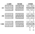
- FIG. 16 is a diagram showing the displacement, speed, and acceleration of free vibration, forced vibration, and response vibration when forced vibration Jsinpt is applied to the object 301.
- the velocity x ′ is represented by a first derivative of the displacement x
- the acceleration x ′′ is represented by a second derivative of the displacement x.
- Timings (1) and (2) are timings of vibrations 4 times and 8 times, respectively.
- the speed x ′ shown in the equation (5) becomes zero in the following two cases.
- the first case is obtained as the following equation (7).
- acceleration x ′′ are both zero.
- Equation (7) the condition obtained from Equation (7) is when the object 301 is vibrated m times when a is an even number. This is the same as the condition shown in FIG. If a is an odd number, both n and m are even numbers, and the object 301 is vibrated (m / 2) ⁇ a times.
- (2k-1) represents that m is an odd number
- (2l-1) represents that n is an odd number
- Equation (8) the condition obtained from Equation (8) is when n and m are both odd numbers and the object 301 is vibrated (m / 2) ⁇ a times at the frequency f1.
- This condition includes a condition that is obtained from Expression (7), and when a is an odd number, both n and m are even numbers and the object 301 is vibrated (m / 2) ⁇ a times. It is.
- the speed x ′ shown in the equation (5) becomes 0 when the object 301 is vibrated m times at the frequency f1 when a is an even number, and n ,
- the object 301 is vibrated (m / 2) ⁇ a times at the frequency f1.
- the former is the same as the condition shown in FIG. 14, the latter condition is newly obtained here.
- the latter condition is when the object 301 is vibrated (m / 2) ⁇ a times at the frequency f1 when n and m are both odd numbers. This condition will be described with reference to FIG.
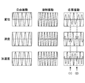
- FIG. 17 shows the displacement, velocity, and acceleration of free vibration, forced vibration, and response vibration when the object 301 is vibrated (m / 2) ⁇ a times at a frequency f1 when n and m are odd numbers.
- Timings (1) and (2) are timings of 5/2 times and 5 times of vibration, respectively.
- the displacement, speed, and acceleration of the response vibration are all 0 at the timing (1) when the vibration is applied 5/2 times. Also, at the timing (2) when the vibration is applied five times, the displacement, speed, and acceleration of the response vibration are all zero. Timing (2) corresponds to the case where m and n are odd numbers in the operating conditions shown in FIG.
- the displacement, velocity, and acceleration of the response vibration can be all zero.
- waveform data 240 representing a drive signal for driving the LRA 140
- waveform data that vibrates (m / 2) ⁇ a times at a frequency f1 ( (m / n) ⁇ f0) when both n and m are odd numbers.
- FIG. 18 is a diagram showing the relationship between the frequency of forced vibration and the vibration time.
- FIG. 18 shows the operating point at timing (1) and the operating point at timing (2) shown in FIG.
- the click feeling presented at timing (1) is realized with a vibration period that is half of the click feeling presented at timing (2). For this reason, when the frequency of forced vibration is set between 200 Hz and 500 Hz, the operating point at timing (1) is obtained so as to interpolate between the operating points at timing (2). In particular, since the operating point of timing (2) becomes discrete on the high frequency side, it is advantageous to interpolate at the operating point of timing (1) in this way.
- an operating point that can be actually selected when setting the frequency of forced vibration, in consideration of restrictions such as the natural frequency of the touch panel 120 or the operating point being on the high frequency side, an operating point that can be actually selected. Is limited.
- any of the displacement, speed, and acceleration of the response vibration becomes 0 at the timings (1) and (2) with the drive signal as described above. It may not be.
- FIG. 19 is a diagram showing the displacement, velocity, and acceleration of free vibration, forced vibration, and response vibration when there is a relatively large damping in the free vibration.
- the displacement x of the free vibration of the LRA 140 shown in FIG. 19 is attenuated over time as compared with the free vibration (no attenuation) shown in FIG. For this reason, the velocity x ′ and the acceleration x ′′ are also attenuated with time.
- the response vibration speed x ′ is not zero. This is because the free vibration of the LRA 140 is attenuated, but the forced vibration is the same as the waveform shown in FIG. 16, so the waveform of the response vibration obtained by combining the free vibration and the forced vibration is different from the waveform shown in FIG. This is because it becomes a waveform.
- the attenuation rate of free vibration is obtained based on the acceleration of free vibration.
- the reason why the attenuation rate is obtained based on the acceleration of the free vibration is that the acceleration can be measured with an accelerometer relatively easily among the displacement, speed, and acceleration of the free vibration.
- the characteristic of a human sensory device is suitable for an acceleration sensor. For example, in the measurement system 400 shown in FIG. 20, the acceleration of free vibration can be obtained.
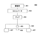
- FIG. 20 is a diagram showing a measurement system 400 that measures the acceleration of free vibration.
- the measurement system 400 includes a drive unit 401, a DA (Digital-to-Analog) converter 402, an amplifier 403, a weight 404, a vibrator 405, an accelerometer 406, and a sponge 407.
- DA Digital-to-Analog
- the drive unit 401 holds predetermined waveform data and outputs a drive signal represented by the waveform data to the DA converter 402.
- the predetermined waveform data is desirably waveform data 240 that realizes forced vibration.
- the weight 404 may be a weight having the same weight as the touch panel 120. Instead of the weight 404, a member to which the LRA 140 is actually attached may be used. As shown in FIG. 3, when the LRA 140 is attached to the touch panel 120, the touch panel 120 may be used instead of the weight 404.
- a vibrator 405 is attached near the center of the weight 404, and an accelerometer 406 is attached to the weight 404.
- the end of the weight 404 is installed on an installation table or the like via a sponge 407.
- the drive signal is output from the drive unit 401 to the DA converter 402, and the drive signal converted into an analog signal by the DA converter 402 is amplified by the amplifier 403 and input to the vibrator 405.
- the vibrator 405 may be an LRA.
- the vibrator 405 is driven by a drive signal supplied from the amplifier 403, and the weight 404 vibrates. If the free vibration of the LRA 140 is measured with the accelerometer 406 after the drive signal is turned off, the damping characteristic of the free vibration of the LRA 140 can be obtained.
- FIG. 21 is a diagram showing the attenuation of the acceleration of free vibration.
- the attenuation of this free vibration is measured by the accelerometer 406, data of the envelope 410 representing the attenuation characteristic of the free vibration as shown by a thick line in FIG.
- the envelope 410 can be obtained by using, for example, Hilbert transform.
- ⁇ is a coefficient representing the attenuation rate
- the response vibration displacement x, velocity x ′, and acceleration x ′′ are all obtained by multiplying the response vibration displacement x, velocity x ′, and acceleration x ′′ by the damping characteristics obtained in this way. Get the operating point to be zero.
- the drive signal Z1 multiplied by the attenuation characteristic is expressed by the following equation.
- Z1 A (e ⁇ t ) sin2 ⁇ f1t
- the displacement, speed, and acceleration of the response vibration when the LRA 140 is driven using this drive signal Z1 are as shown in FIG.
- FIG. 22 is a diagram showing the displacement, speed, and acceleration of free vibration, forced vibration, and response vibration when the LRA 140 is driven by the drive signal Z1.
- the response vibration displacement x, velocity x ′, and acceleration x ′′ are all 0 at both timings (1) and (2).
- FIG. 23 is a diagram showing the difference in residual vibration depending on the presence or absence of damping characteristics.
- FIG. 23A shows the acceleration of free vibration that occurs after the drive signal Z not multiplied by the attenuation characteristic is input and the drive signal Z is turned off at time t1.
- FIG. 23 (A) As can be seen by comparing FIG. 23 (A) and FIG. 23 (B), after time t1, relatively large residual vibration remains in FIG. 23 (A), whereas residual vibration in FIG. 23 (B). It can be seen that it hardly occurred.
- the acceleration after time t1 in FIG. 23B is 0.02 G or less, which is a level that humans cannot perceive.
- the displacement x of the response vibration the velocity x ′
- the timing at which all of the acceleration x ′′ becomes 0 can be reliably obtained.
- a click feeling can be presented by the vibration generated by the LRA 140 by using the driving signal as the waveform data 240 representing the driving signal for driving the LRA 140 and using the driving signal as the attenuation factor indicating the attenuation characteristic of the free vibration.
- the drive signal before the attenuation rate indicating the attenuation characteristic of free vibration is included in the drive signal, for example, any of the following two may be used.
- a signal that vibrates the LRA 140 m times with a signal of a frequency f1 that satisfies f1 (m / n) ⁇ f0 (m and n are natural numbers other than 0 and m ⁇ n).
- a drive signal can be used. In this case, the vibration shown in FIG.
- waveform data 240 representing a drive signal for driving the LRA 140
- waveform data that vibrates (m / 2) ⁇ a times at a frequency f1 ( (m / n) ⁇ f0) when both n and m are odd numbers.
- a drive signal representing the above may be used. In this case, the vibration shown in FIG.
- the drive signal is a sine wave.
- the drive signal is not limited to a sine wave, and may be a waveform other than a sine wave such as a rectangular wave.
- the LRA 140 is attached to the casing-side surface of the touch panel 120.
- the present invention is not limited to this.
- the LRA 140 may be disposed in the vicinity of the substrate 150 disposed in the housing 110.
- FIG. 24 is a diagram illustrating an example of an electronic device in which the LRA 140 is provided in the housing.
- the LRA 140 is disposed in the vicinity of the substrate 150 provided in the housing 110.
- the first embodiment can also be applied to electronic device 100A. Further, when the first embodiment is applied to the electronic device 100A, it is possible to express a click feeling when the metal dome type button 2 is pressed as in the electronic device 100 of the first embodiment.
- This is a driving condition in which the LRA 140 is vibrated m times with a driving signal including f1.
- This is a driving condition for vibrating a times.
- the drive condition is that the LRA 140 is vibrated m times with a drive signal multiplied by the attenuation characteristic depending on the attenuation factor of the vibration system on which the LRA 140 is mounted.
- This is a drive condition that vibrates (m / 2) ⁇ a times with a drive signal multiplied by the attenuation characteristic depending on the attenuation rate of the vibration system.
- the resonance frequency of the LRA 140 has a characteristic that changes according to the acceleration amplitude, there is a possibility that the residual vibration cannot be reduced with the above-described four drive signals.
- the characteristic that the resonance frequency changes according to the acceleration amplitude is, for example, a characteristic that the resonance frequency shifts to the high frequency side as the acceleration amplitude increases.
- the acceleration amplitude is synonymous with acceleration, and its unit is m / s 2 or G (Gravity).
- FIG. 25 is a diagram showing deformation characteristics of the gradually hardening spring and the linear spring.
- the horizontal axis represents the amount of deformation
- the vertical axis represents the force applied to the gradually hardening spring and the linear spring.
- the solid line indicates the deformation characteristic of the gradually hardening spring
- the broken line indicates the deformation characteristic of the linear spring.
- the amount of deformation of the linear spring increases linearly as the force increases.
- the amount of deformation of the gradually hardening spring decreases as the force increases.
- the gradually hardening spring has a non-linear deformation characteristic.
- 26 and 27 are diagrams showing characteristics in which the resonance frequency changes according to the acceleration amplitude.
- the LRA 140 has such characteristics when, for example, the thickness of the LRA 140 is reduced as the size of the LRA 140 is reduced, and the amount of deformation with respect to stress is not linear but nonlinear.
- the rated value of the resonance frequency of the LRA 140 is f0 and the drive voltage of the LRA 140 is set to any one of 15V, 35V, 55V, and 75V and the frequency is changed, the frequency characteristics shown in FIG. 26 are obtained.
- the frequency at which the acceleration takes a peak in the frequency characteristics is the resonance frequency. As shown in FIG. 26, the peak of the frequency characteristic is shifted to the high frequency side as the drive voltage increases and the acceleration (acceleration amplitude) increases.
- FIG. 27 is an enlarged view of a part of FIG. 26, and shows frequency characteristics when drive voltages are 10V, 15V, 25V, 35V, 45V, 55V, 65V, and 75V. As shown in FIG. 27, as the acceleration increases due to an increase in the drive voltage, the resonance frequency f0 is shifted to the high frequency side as indicated by a thick dashed line.
- the resonance frequency f0 shifts to the high frequency side as the acceleration increases, because the amount of deformation decreases on the high frequency side due to the deformation characteristics like the gradually hardening spring of the LRA 140. It is thought to be higher.
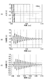
- the drive signal and response vibration displacement when the LRA 140 is vibrated five times will be described. That is, FIG.
- FIG. 28 is a diagram showing the waveform of the drive signal of the LRA 140 and the displacement of the response vibration.
- 28A shows a waveform when the resonance frequency f0 is 205 Hz
- FIG. 28B shows a waveform when the resonance frequency f0 is 210 Hz
- FIG. 28C shows a resonance frequency f0 of 215 Hz
- FIG. 28D shows a resonance frequency f0 of 225 Hz.
- the waveform of the drive signal is indicated by a broken line
- the displacement of the response vibration is indicated by a solid line.
- the displacement of the response vibration shown in FIG. 28 is the case where the LRA 140 has a characteristic that the resonance frequency changes according to the acceleration amplitude.
- the displacement of the response vibration shown in FIG. 28 is obtained with the LRA 140 attached to the touch panel 120 as shown in FIG.
- the residual vibration of the response vibration after time t2 in FIG. 28 (A) has an acceleration of about 0.02 G or more, and is an acceleration with a strength perceived by humans. For this reason, in FIG. 28A, after time t2 when the drive signal is turned off, residual vibration that can be perceived by humans has occurred, and it is difficult to present a click feeling. This also applies to (B), (C), and (D) of FIG.
- the residual vibration is at a level that cannot be perceived by humans. To suppress.
- a specific method will be described.
- FIG. 29 is a diagram showing a drive signal waveform and a response vibration displacement by the drive control method of the LRA 140 of the first embodiment.
- FIG. 29A shows the displacement of the response vibration when a drive signal having a damping characteristic at a frequency of 210 Hz ⁇ (5/4) is input to the LRA 140 for five periods under the third drive condition.
- the displacement of the response vibration shown in FIG. 29A is the same as the displacement of the response vibration shown in FIG. 28B, and the resonance frequency of the LRA 140 changes according to the acceleration amplitude.
- the displacement of the response vibration shown in FIG. 29 is obtained with the LRA 140 attached to the touch panel 120 as shown in FIG.
- the frequency of response vibration is about 205 Hz, and the amplitude of the response vibration is maximized.
- the frequency of the response signal is about 215 Hz.
- drive control of LRA 140 is performed using characteristic q (t) in which the frequency of the drive signal of LRA 140 changes from 205 Hz to 215 Hz to 205 Hz in accordance with a change in time t. I do.
- the drive signal and the response vibration displacement when the LRA 140 is vibrated five times using the drive signal obtained by multiplying the drive signal by the attenuation characteristic are shown.
- the characteristic q (t) is such that the frequency of response vibration displacement shown in FIG. 29A increases from 205 Hz at time t1 to 215 Hz at time t1A and then decreases to 205 Hz at time t2. It has a time-varying characteristic that changes. This characteristic q (t) will be described later.
- the drive control of the LRA 140 is performed by changing the frequency of the drive signal with the passage of time according to the characteristic that the resonance frequency of the LRA 140 changes according to the acceleration amplitude.
- FIG. 30 is a diagram (part 1) showing step by step a method for generating a drive signal for the LRA 140 of the first embodiment.
- the LRA 140 is driven by inputting a sinusoidal drive signal, and the steady amplitude of the acceleration of the response vibration of the LRA 140 is measured.
- the frequency f of the sinusoidal drive signal is set to the rated value of the resonance frequency of the LRA 140 and a plurality of values before and after the rated value, and the steady amplitude of the acceleration of the response vibration when driving at a plurality of frequencies is measured.
- the steady amplitude of the response vibration acceleration is measured with the LRA 140 attached to the touch panel 120 as shown in FIG.
- the rated value of the resonance frequency of the LRA 140 is 225 Hz and the actual resonance frequency of the LRA 140 can exist in the range of 205 Hz to 235 Hz due to an error in the resonance frequency
- a margin of about 5 Hz is taken as an example, and the 200 Hz In the range of ⁇ 240 Hz
- a sinusoidal drive signal having a plurality of frequencies f is input to the LRA 140 to measure the steady amplitude of the response vibration acceleration.
- the range of the resonance frequency in consideration of the error is 205 Hz to 235 Hz, and the range in which a margin is given to this range is 200 Hz to 240 Hz.
- a plurality of sinusoidal drive signals having different frequencies f by 1 Hz are input to the LRA 140 and the steady amplitude of the acceleration of the response vibration is measured. As shown, the acceleration characteristic with respect to the frequency f of the drive signal is obtained. A plurality of points shown in FIG. 30A indicate steady amplitudes of accelerations of response vibrations obtained at the respective frequencies f.
- a curve obtained by interpolating the steady amplitude of the acceleration of the response vibration with respect to the frequency f shown in FIG. an expression representing a curve that applies to a plurality of points shown in FIG.
- the curve thus obtained is the curve shown in FIG. 30B, and this curve is represented by a function G (f) of the frequency f.
- the function G (f) represents the characteristic of the steady amplitude of the acceleration of the response vibration with respect to the frequency f.
- the frequency f12 is a frequency at which the steady-state amplitude of acceleration when the LRA 140 is driven at the rated maximum voltage is maximum.
- the inverse function f (G) is obtained as a characteristic that the frequency f on the vertical axis changes with respect to the change in the acceleration G on the horizontal axis.
- the characteristic q (t) and the best resonance frequency f0 are obtained while changing the resonance frequency f0 from 200 Hz to 240 Hz.
- steps S1 to S7 are repeatedly executed while changing the resonance frequency f0 from 200 Hz to 240 Hz.
- the range of the resonance frequency f0 from 200 Hz to 240 Hz is a range obtained in consideration of the resonance frequency error and the margin (5 Hz) as described above.
- FIG. 31 is a diagram (part 2) illustrating a method for generating a drive signal for the LRA 140 of the first embodiment step by step.
- the LRA 140 is driven with being attached to the touch panel 120 as shown in FIG.
- step S1 the LRA 140 is driven using any one of the first to fourth driving conditions described above.
- the LRA 140 is driven under the third driving condition.
- the resonance frequency f0 is initially set to 200 Hz, and the LRA 140 is driven under the third driving condition.
- This is a drive condition in which the LRA 140 is vibrated m times by a drive signal obtained by multiplying the drive signal including f1 by the attenuation characteristic due to the attenuation rate of the vibration system on which the LRA 140 is mounted.
- This drive signal Z1 has a waveform as shown in FIG.
- step S2 the acceleration of the response vibration obtained by driving the LRA 140 with the drive signal Z1 shown in FIG.
- the acceleration of the response vibration is represented by the waveform shown in FIG.
- the acceleration data is a time-series discrete value.
- the acceleration envelope data w is a time-series discrete value representing the envelope indicated by a broken line in FIG. 31B, and represents the envelope connecting the maximum acceleration values.
- time-series data b [b0,..., Bi,. Since each value (w0 ⁇ wn) of the envelope data represents acceleration, it can be substituted for the acceleration G of the inverse function f (G).
- a characteristic q (t) shown in (D) of FIG. 31 is obtained.
- the characteristic q (t) represents the characteristic shown in (D) of FIG.
- a characteristic q (t) represents a time characteristic in which the resonance frequency of the LRA 140 illustrated in FIG. 29A changes with time.
- the LRA 140 whose resonance frequency changes according to the acceleration amplitude is driven, the acceleration changes according to the time change, so that the resonance frequency changes as time passes.
- the characteristic q (t) represents a time characteristic in which the resonance frequency changes with time.
- FIG. 32 is a diagram (part 3) showing step by step a method of generating a drive signal for the LRA 140 of the first embodiment.
- the LRA 140 is driven in a state of being attached to the touch panel 120 as shown in FIG.
- the drive signal Z2 (t) is as shown in FIG. 32A and is expressed by the following equation.
- Z2 (t) A (e ⁇ t ) sin2 ⁇ (m / n) q (t) t
- step S7 the LRA 140 is driven using the drive signal Z2 (t), and the residual vibration amplitude shown in FIG. 32B is measured as error.
- steps S1 to S7 are repeated to measure the amplitude error of the residual vibration.
- the residual vibration amplitude error for a plurality of f0 is measured.
- the resonance frequency f0 is obtained as 210 Hz.
- the best resonance frequency f0 is an example of the frequency f2.
- the frequency f2 is a frequency included in the range of the resonance frequency f0 considering the error.
- the resonance frequency f0 that minimizes the residual vibration amplitude error is obtained as described above.
- the time characteristic q (t) in which the resonance frequency of the LRA 140 changes with the passage of time is represented by the drive signal.
- the data representing the time characteristic q (t) at which the resonance frequency of the LRA 140 changes with time is discrete numerical data, and if stored in the memory 220 as the waveform data 240 (see FIG. 5). Good.
- the time characteristic (q (t)) in which the resonance frequency of the LRA 140 changes with the passage of time under the first to fourth driving conditions The required form has been described. However, by using a drive signal under a drive condition other than the first to fourth drive conditions, a time characteristic (q (t)) in which the resonance frequency of the LRA 140 changes with time is obtained, and the LRA 140 is driven. You may make it do.
- the time characteristic q (t) is obtained from the envelope data of the acceleration of the response vibration (see FIG. 31B).
- the method of obtaining the time characteristic q (t) is limited to such a method. I can't.
- the time characteristic q (t) may be obtained by approximating the displacement of the response vibration in FIG. 31B with a sine wave.
- the second embodiment will be described below with reference to the drawings.
- the second embodiment is an example in which the resonance frequency f0 of the LRA 140 is a value measured in a state where the resonance frequency f0 is incorporated in the electronic device 100.
- the resonance frequency f0 of the LRA 140 is a value measured in a state where the resonance frequency f0 is incorporated in the electronic device 100.
- the description of the second embodiment only differences from the first embodiment will be described.
- components having the same functions as those in the first embodiment are given the same reference numerals as those used in the description of the first embodiment, and description thereof is omitted.
- the resonance frequency f0 ′ of the touch panel 120 in a state where the LRA 140 is incorporated in the electronic device 100 is measured.
- the resonance frequency f0 ′ is used when calculating the frequency f1 of the drive signal Z.
- FIG. 33 is a diagram for explaining the driving apparatus of the second embodiment.
- the driving device 200A of the second embodiment includes a CPU 210A and a memory 220A.
- the CPU 210 reads and executes a frequency measurement program 255 described later from the memory 220A, thereby measuring and resetting a resonance frequency f0 ′ described later.
- the frequency measurement program 255 and the design value data 256 are stored in the memory 220A.
- the frequency measurement program 255 causes the CPU 210 to perform a measurement process of the resonance frequency f0 ′ of the LRA 140 when the LRA 140 is incorporated in the electronic device 100, for example.
- the design value data 256 is a value determined when the electronic device 100 is designed.
- the design value data 256 of the second embodiment is, for example, the resonance frequency f0 unique to the LRA 140.
- FIG. 34 is a flowchart for explaining the resonance frequency measurement process according to the second embodiment.
- the CPU 0210 reads the frequency measurement program 255.
- the measurement instruction of the resonance frequency f0 ′ is given, for example, when the process of incorporating the LRA 140 and the touch panel 120 into the housing 110 is completed in the manufacturing process of the electronic device 100, or at the time of factory shipment. .
- the frequency measurement program 255 causes the CPU 210 to apply a sine wave having a plurality of frequencies as a drive signal to the LRA 140 in a predetermined frequency band (step S1702). Specifically, for example, the CPU 210 applies a drive signal to the LRA 140 from 100 Hz to 300 Hz, such as a sine wave with a frequency of 100 Hz, a sine wave with a frequency of 110 Hz,..., A sine wave with a frequency of 290 Hz, and a sine wave with a frequency of 300 Hz. To do.
- the frequency measurement program 255 causes the CPU 210 to store the maximum value of vibration acceleration of the touch panel 120 for each drive signal having a different frequency in the memory 220A (step S1703).
- electronic device 100 includes an acceleration sensor (not shown), and detects the maximum value of acceleration of vibration of touch panel 120 each time drive signals having different frequencies are applied to LRA 140.
- the memory 220 is provided with an area for storing the calculation result obtained by the frequency measurement program 255, and the maximum acceleration value for each drive signal is temporarily stored in this area.
- the frequency measurement program 255 causes the CPU 210 to select the frequency of the drive signal that maximizes the acceleration among the accelerations stored in the memory 220A (step S1704). Subsequently, the frequency measurement program 255 sets the frequency of the selected drive signal as the resonance frequency f0 ′, and causes the CPU 210 to overwrite the design value data 256 of the memory 220A with the resonance frequency f0 ′ (step S1705).
- Embodiment 2 can directly provide the user with a tactile sensation of a short-time waveform that rapidly attenuates in one to several cycles, and can express a click feeling.
- the resonance frequency f0 ′ is performed by the frequency measurement program 255.
- the resonance frequency f0 ′ may be measured outside the electronic device 100 and overwritten on the design value data 256 of the memory 220A. .
- the second embodiment can also be applied to the electronic device 100A.
Landscapes
- Engineering & Computer Science (AREA)
- General Engineering & Computer Science (AREA)
- Theoretical Computer Science (AREA)
- Physics & Mathematics (AREA)
- Human Computer Interaction (AREA)
- General Physics & Mathematics (AREA)
- Mechanical Engineering (AREA)
- Electromagnetism (AREA)
- Apparatuses For Generation Of Mechanical Vibrations (AREA)
- User Interface Of Digital Computer (AREA)
- Power Engineering (AREA)
Abstract
操作に応じた触感を提供できる駆動装置、電子機器、駆動制御プログラム、及び駆動信号の生成方法を提供する。 駆動装置は、共振周波数が加速度振幅に応じて定格値f0を含む第1から第2共振周波数の範囲で変化する振動生成装置を共振周波数の時間特性q(t)に対して、周波数f1=(m/n)×q(t)を満たす正弦波でありm回加振する駆動信号(m,nは互いに異なる0以外の自然数)、又は、(m/2)×a(aは0以外の自然数)回加振する駆動信号(m,nは互いに異なる正の奇数)を表す波形データが格納される記憶部と、駆動信号を振動生成装置へ出力する駆動処理部とを含み、時間特性q(t)は、周波数f1=(m/n)×f2を満たす正弦波であり、m≠nの場合に振動生成装置をm回加振する駆動信号、又は、(m/2)×a回加振する駆動信号(m,nは互いに異なる正の奇数)で振動生成装置を駆動して得られる時間特性である。
Description
本発明は、振動生成装置を駆動させる駆動装置、電子機器、駆動制御プログラム、及び駆動信号の生成方法に関する。
従来から、表面を有し且つ撓み波を支持可能なパネルと、前記表面に関連付けられたタッチ感知式入力デバイスと、前記入力デバイスに力フィードバックを与えるための力変換器を含む手段とを備えるユーザ/機械インタフェースがある。前記力が前記パネルに対するパルス形式のものであり、前記パルスが、ボタンクリック感覚をユーザの指先に提供するような変調信号の形式であり、前記変調信号が150~750Hzの範囲の基調搬送周波数を有し且つ少なくとも10msの持続時間である(例えば、特許文献1参照)。
しかしながら、従来の装置では、振動生成装置の共振周波数が加速度振幅に応じて変化する場合に、良好な触感を提供することが困難である。
そこで開示の技術は、振動生成装置の共振周波数が加速度振幅に応じて変化する場合に、操作に応じた触感を提供することが可能な駆動装置、電子機器及び駆動制御プログラムを提供することを目的とする。
開示の一態様の駆動装置は、共振周波数の定格値がf0である振動生成装置であって、前記共振周波数が加速度振幅に応じて前記定格値f0を含む第1共振周波数f11から第2共振周波数f12の範囲で変化する周波数特性を有する振動生成装置を、前記共振周波数の時間特性q(t)に対して、周波数f1=(m/n)×q(t)(m,nは互いに異なる0以外の自然数)を満たす正弦波であり、且つ前記振動生成装置をm回加振する第1駆動信号、又は、周波数f1=(m/n)×q(t)(m,nは互いに異なる正の奇数)を満たす正弦波であり、且つ前記振動生成装置を(m/2)×a(aは0以外の自然数)回加振する第2駆動信号を表す波形データが格納された記憶部と、前記記憶部に格納された前記波形データを読み出し、前記波形データに対応する前記第1駆動信号又は前記第2駆動信号を前記振動生成装置へ出力する駆動処理部と、を含み、前記時間特性q(t)は、誤差を考慮した前記共振周波数の範囲に含まれる周波数f2に対して、周波数f1=(m/n)×f2(m,nは互いに異なる0以外の自然数)を満たす正弦波であり、且つ前記振動生成装置をm回加振する第3駆動信号、又は、周波数f1=(m/n)×f2(m,nは互いに異なる正の奇数)を満たす正弦波であり、且つ前記振動生成装置を(m/2)×a(aは0以外の自然数)回加振する第4駆動信号で前記振動生成装置を駆動したときに得られる、前記振動生成装置の共振周波数が時間経過に応じて変化する時間特性である。
開示の技術によれば、振動生成装置の共振周波数が加速度振幅に応じて変化する場合に、操作に応じた触感を提供することができる。
<実施の形態1>
以下に図1を参照して実施の形態1の概要について説明する。図1は、実施の形態1の概要を説明する図である。
以下に図1を参照して実施の形態1の概要について説明する。図1は、実施の形態1の概要を説明する図である。
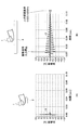
図1(A)は、人間の指に加速度計1を取り付けてボタン2を押下した際に生じる振動の加速度の波形11を示す図である。図1(B)は、人間の指に加速度計1を取り付けて、LRA(Linear Resonant Actuator)が取り付けられたタッチパネル3をタッチした際に生じる振動の加速度の波形12を示す図である。図1の例では、ボタン2は例えばメタルドーム式のボタンである。またボタン2とタッチパネル3は、電子機器に設けられたものである。
波形11で示される振動は、1~数周期で急速に減衰する。これに対して波形12で示される振動は、駆動信号の供給を停止後もLRAの固有振動数による自由振動が減衰するまで続く。以下の説明では、駆動信号の供給停止後も続くLRAの固有振動数による自由振動を残留振動と呼ぶ。
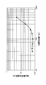
ところで、人間の指は、振動周波数200Hzにおいて振動の加速度が0.02G以下になると振動を感知できなくなる。振動周波数とは、1秒間の振動数である。振動の加速度とは、単位時間当たりの振動の速度変化量を示すものである。図2は、人の加速度器官の感度を示す図である。尚人間の加速度を感知する器官は、パチニ小体である。パチニ小体は、主に皮膚に見られる主要な4種類の機械受容体のうちの1つである。
すなわち波形11では、指は0.01sec以内に振動の加速度が0.02G以下とるため振動を感知しなくなる。これに対して波形12では、振動の加速度が0.02G以下になるまで0.1secが必要であり、指は0.1sec経過するまで振動を感知し続ける。したがって波形11で示される振動と、波形12で示される振動とでは、人間が感知する触感として全く異なるものとなる。
そこで実施の形態1では、残留振動を抑制することで1~数周期で急速に減衰する振動を発生させ、クリック感を表現する。
実施の形態1では、特定の条件を満たす駆動信号をLRA140に供給したときにLRA140の振動が1~数周期で停止し残留振動が発生しないことに着目し、この特定の条件を満たす駆動信号をLRA140に印加する。
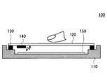
以下に図3を参照して実施の形態1の電子機器について説明する。図3は、実施の形態1の電子機器を説明する図である。
実施の形態1の電子機器は、例えば表示機能と入力機能とを有するタッチパネルを入力手段として有する機器であれば良い。例えば実施の形態1の電子機器は、スマートフォン、タブレット型コンピュータ、携帯情報端末機等であっても良い。
実施の形態1の電子機器100は、筐体110、タッチパネル120、両面テープ130、LRA140、基板150を有する。
実施の形態1の電子機器100では、両面テープ130により、タッチパネル120が筐体110に固定されている。LRA140は、タッチパネル120の筐体側の面に取り付けられている。LRA140は、予め設計された共振周波数を持つ振動系とアクチュエータとが組み合わされたもので、主に共振周波数で駆動して振動を発生させる振動生成装置であり、駆動波形の振幅により振動量が変化する。LRA140の詳細は後述する。尚実施の形態1ではLRA140を振動生成装置としたが、共振器と加振用のアクチュエータを備えた構造であればLRAに限らない。
基板150は、筐体110内部に配置されている。基板150には、LRA140の駆動を制御するために駆動装置やLRA140に駆動信号を出力するドライバICが実装されている。
実施の形態1の電子機器100は、タッチパネル120にユーザの指が接触すると、この接触を感知して基板150に実装された駆動装置によりLRA140を駆動し、LRA140の振動をタッチパネル120に伝播させる。
尚実施の形態1の電子機器100は、タッチパネル120を入力操作部とする機器であればよいため、例えばATM(Automatic Teller Machine)のように特定の場所に設置されて利用される機器であってもよい。
以下に図4を参照してLRA140について説明する。図4は、LRAの例を示す図である。図4(A)はボイスコイルを用いたLRAの例を示す図であり、図4(B)は圧電素子を用いたLRAの例を示す図である。
図4(A)に示すLRA30は、ばね31、磁石32、コイル33を有する。LRA30は、ばね31のばね定数をkとし、磁石32の質量をmとすると、固有振動数f0が以下の式(1)で示される。

次に図5を参照して実施の形態1の電子機器100の有する基板150に実装された駆動装置について説明する。図5は、実施の形態1の駆動装置を説明する図である。
実施の形態1の駆動装置200は、CPU(Central Processing Unit)210と、メモリ220とを有する。CPU210は、メモリ220に格納された駆動制御プログラム230を読み出して実行することで、後述するLRA140の駆動処理を行う。メモリ220には、LRA140の駆動を制御する駆動制御プログラム230が格納される記憶領域と、波形データ240が格納される記憶領域と、触感を提供するAPI(Application Programming Interface)250が格納される記憶領域とが設けられている。
駆動制御プログラム230は、CPU210にLRA140の駆動制御を実行させる。波形データ240は、LRA140により生じる振動によりクリック感を表現するために予め生成された駆動波形のデータである。波形データ240の詳細は後述する。API250は、駆動制御プログラム230により起動され、触感を提供するための各種処理を行う。API250は、図5ではAPI250はメモリ220に格納されるものとしたが、基板150に実装された他のメモリに格納されていても良い。
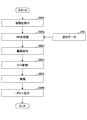
図6は、実施の形態1の駆動装置によるLRA140の駆動を説明するフローチャートである。
実施の形態1の駆動装置200は、タッチパネル120に対する接触を検出すると(ステップS601)、API250を起動させる(ステップS602)。具体的には駆動装置200は、例えばタッチパネル120上に表示されたボタンに対する接触があった場合等にAPI250を起動しても良い。
API250は、メモリ220に格納された波形データ240を読み出し、波形データ240に対応した駆動指令をドライバIC260へ出力する(ステップS603)。ドライバIC260は、駆動指令を受けて波形データ240をD/A(Digital to Analog)変換し(ステップS604)、アンプ等により増幅する(ステップS605)。ドライバIC260は、増幅した信号をLRA140に対して出力する(ステップS606)。
以下に実施の形態1の波形データ240について説明する。実施の形態1の波形データ240は、残留振動を停止させる特定の条件を満たす駆動信号の波形を示すデータである。
特定の条件を満たす駆動信号は、LRA140の固有振動数(以下、共振周波数)をf0としたとき、f1=(m/n)×f0(m,nは、0以外の自然数かつm≠n)となる周波数f1の信号でLRA140をm回加振する信号である。
図7は、実施の形態1のLRA140の模式図の例を示す図であり、図8は、実施の形態1のLRA140の駆動信号の例を示す図である。
実施の形態1のLRA140は、図7に示すように共振周波数f0=175Hz、重りの重さを1.5g、重りを支持するばね定数を1813.5N/mのものとした。
実施の形態1の駆動信号は、m=2,n=1としたとき、駆動信号の周波数f1=2/1×175=350Hzとなる。周波数をf1としたときの駆動信号Zは、図8に示す波形となる。図8の例では、駆動信号Z=0.01sin2πf1tとなる。図8の駆動信号Zは、m=2であるから2周期の正弦波である。
実施の形態1では、例えば図8に示す駆動信号Zを示すデータが波形データ240としてメモリ220に格納される。波形データ240は、例えば駆動信号Zの周波数f1の値と、振幅と位相の値と、m,nの値等を含んでいても良い。また波形データ240は、駆動信号Zの波形そのものを示すデータであっても良い。
また実施の形態1では、駆動信号Zの周波数f1は、m/n×f0に対して誤差が1%以下となるように設定することが好ましい。このように周波数f1を設定すれば、駆動信号の印加を停止した後に残留振動が生じたとしても、振動の加速度は人の感知下限である0.02G以下となり人に感知されないため、クリック感を損ねることがない。
実施の形態1の駆動装置200は、図6のステップS603において、API250により、駆動信号Zを示す波形データ240を読み出し、波形データ240に対応した駆動指令をドライバIC260へ出力する。ドライバIC260は、波形データ240をD/A変換して増幅し、LRA140に出力する。
実施の形態1の駆動装置200において、LRA140に駆動信号Zが印加された場合について説明する。
駆動信号ZがLRA140に印加されると、LRA140には、周波数f1の強制振動とLRA140の共振周波数f0の自由振動が生じ、LRA140の変位はこれらの合成波となる。
図9は、LRAの変位を説明する図である。図9(A)は、変位を説明する第一の図であり、図9(B)は変位を説明する第二の図である。
図9(A)において、点線で示される波形はLRA140に駆動信号Zが印加されたときに生じる振動変位の強制振動成分y1を示し、実線で示される波形は自由振動成分y2を示す。駆動信号ZがLRA140に印加されたときの応答変位y3は、強制振動成分y1と自由振動成分y2との合成波となる。
図9(B)は、応答変位y3の例を示す図である。応答変位y3は、駆動信号Zが0となるタイミングTにおいて0となることがわかる。
応答変位y3が0となるタイミングTにおいて、LRA140の振動の速度、振動の加速度ともに0になるため、LRA140の振動は停止する。
図10は、LRA140の振動の速度及び振動の加速度の例を示す図である。図10(A)は応答変位y3の波形を示す図であり、図10(B)は応答変位y3の微分である速度の波形y3′の波形を示す図であり、図10(C)は応答変位y3の2回微分である加速度の波形y3″の波形を示す図である。
図10からわかるように、速度の波形y3′と加速度の波形y3″とは、応答変位y3が0となるタイミングで0となる。すなわちLRA140の振動がタイミングTで停止する。
このとき加速度の波形y3″は、0.01sec以内に2周期で停止する。したがって図10の例では、振動の加速度が0.01sec以内に0.02G以下となり、ボタン2を押下した際のクリック感を表現することができる。
尚実施の形態1では、m=2,n=1としたが、これに限定されない。実施の形態1では、m,nは自然数(0を含まない)かつm≠nを満たせば良い。尚m,nの関係は、m>nを満たす関係であることが好ましい。
以下に図11乃至図14を参照して、実施の形態1の効果を説明する。図11は、LRA140の共振周波数の正弦波を駆動信号としたときのLRA140の振動の加速度を示す図である。
図11(A)は、LRA140の共振周波数f0=175Hzと同一の175Hzの正弦波の駆動信号を示す。図11(B)は、図11(A)の正弦波を駆動信号としてシミュレーションした際のLRA140の振動の加速度を示す。図11(C)は、共振周波数f0=175HzのLRA140を搭載した実機において図11(A)の駆動信号をLRA140に印加した際のタッチパネル120の振動の加速度を示す。尚タッチパネル120の加速度は、タッチパネル120の中央に加速度計を配置して検出したものである。
図11(B),(C)からわかるように、共振周波数f0の正弦波を駆動信号とした場合、残留振動が0.1sec以上に亘り現れる。
尚図11(C)において駆動信号が印加されるLRA140は、共振周波数f0=175Hz、重りの重さを1.5g、重りを支持するばね定数を1813.5N/mのものとした。
図12は、駆動指令によってLRA140に発生する振動の逆位相の電圧を振動抑制信号として加えたときのLRA140の振動の加速度を示す図である。図12(A)は、LRA140の共振周波数f0=175Hzの正弦波の駆動信号を示す。図12(B)は、LRA140を搭載した実機において図12(A)の正弦波を駆動信号とし、且つ駆動信号の供給停止後にLRA140に発生する振動の逆位相の電圧を印加したときのタッチパネル120の振動の加速度を示す。
図12の例では、図11に比べて残留振動は小さくなるが、振動の加速度が人の感知下限の0.02G以下になるまでに0.05sec以上かかる。
図13は、特定の条件を満たさない信号を駆動信号としたときのLRA140の振動の加速度を示す図である。
図13(A)は、特定の条件を満たさない周波数300Hzの正弦波の駆動信号を示す。図13(B)は、図13(A)の正弦波を駆動信号としてシミュレーションした際のLRA140の振動の加速度を示す。図13(C)は、共振周波数f0=175HzのLRA140を搭載した実機において図13(A)の駆動信号を印加した際のタッチパネル120の振動の加速度を示す。
図13の例では、図(B),(C)からわかるように、特定の条件を満たさない周波数の正弦波を駆動信号とした場合、残留振動が0.04sec以上に亘り現れる。
図14は、特定の条件を満たす信号を駆動信号としたときのLRA140の振動の加速度を示す図である。
図14(A)は、特定の条件を満たす周波数350Hzの正弦波の駆動信号を示す。図14(B)は、図14(A)の正弦波を駆動信号としてシミュレーションした際のLRA140の振動の加速度を示す。図14(C)は、共振周波数f0=175HzのLRA140を搭載した実機において図14(A)の駆動信号を印加した際のタッチパネル120の振動の加速度を示す。
図14の例では、図14(B),(C)からわかるように、0.02sec以降は残留振動の加速度が感知下限の0.02G以下となり、振動の波形は短時間の波形となる。
以上から、LRA140による振動の波形は、LRA140の共振周波数をf0としたとき、f1=(m/n)×f0(m,nは、0以外の自然数かつm≠n)となる周波数f1の信号でLRA140をm回加振する信号を駆動信号とすれば、残留振動をなくすことができる。またLRA140を搭載した実機におけるタッチパネル120の振動の加速度の波形は1~数周期で急速に減衰する短時間の波形となり、クリック感を表現することができる。
次に、図15に示す質量Mの物体の変位xについて考える。図15は、物体301とばね302を含む振動系300を示す図である。
物体301の質量はMであり、物体301はばね302の下端に接続されている。ばね302のばね定数はKである。ばね302の上端は固定端であり、ばね302の下端は自由端である。
なお、物体301に力を加えずに、ばね302に物体301を吊り下げた状態における物体301の位置(つり合いの位置)を原点とし、原点に対する物体301の変位をxで表す。変位xは、鉛直下向きが正の方向である。
また、振動系300における物体301の自由振動の固有角振動数をωとすると、固有角振動数ωは次式(3)で表され、自由振動の周波数f0は、f0=ω/2πである。

このように物体301に強制振動を与えると、物体301の変位xは次式(4)で表される。
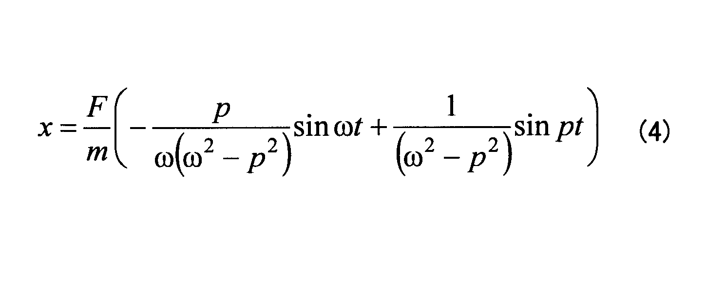
式(4)から明らかなように、物体301の変位xは、自由振動の成分と強制振動の成分とを合成したものとして表される。これは、図9を用いて説明したように、LRA140に駆動信号Zが印加したときに生じる振動変位の強制振動成分y1、自由振動成分y2を用いると、駆動信号ZをLRA140に印加したときの応答変位y3が、強制振動成分y1と自由振動成分y2との合計になることと同様である。
ここで、図14で説明した場合と同様に、特定の条件を満たす正弦波の駆動信号として、物体301に強制振動Jsinptを加えた場合に、式(4)で表される自由振動、強制振動、及び応答振動は、図16に示す通りである。応答振動は、自由振動と強制振動を合成した振動として与えられる。
図16は、物体301に強制振動Jsinptを加えたときの自由振動、強制振動、及び応答振動の変位、速度、及び加速度を示す図である。速度x'は、変位xの一次微分で表され、加速度x''は、変位xの二次微分で表される。
なお、図16には、強制振動の周波数f1がf1=5/4×f0の場合(m=5、n=4)に、強制振動によって物体301を加振した場合の波形を示す。
図16に示す応答振動の変位、速度、及び加速度を見て分かるように、変位xが0となるタイミング(1)、(2)において、応答振動の速度及び加速度はともに0になっている。タイミング(1)、(2)は、それぞれ、4回と8回加振したタイミングである。
ここで、応答振動の変位、速度、及び加速度がすべて0になるタイミングが他にも得られないかどうか検討する。
式(4)に示す変位x、変位xの一次微分である速度x'、変位xの二次微分である加速度x''は、次式(5)のように表される。


以上より、式(6)として示す、f1=(m/n)×f0、かつ、t=(2π/p)×(m/2)×aが成立するときに、変位xと加速度x''がともに0になる。すなわち、(m/2)×a回振動したときに、変位xと加速度x''がともに0になる。
また、変位xと加速度x''に加えて、式(5)に示す速度x'が0になるのは、以下の2つのケースがある。まず、第1のケースは次式(7)として求まる。
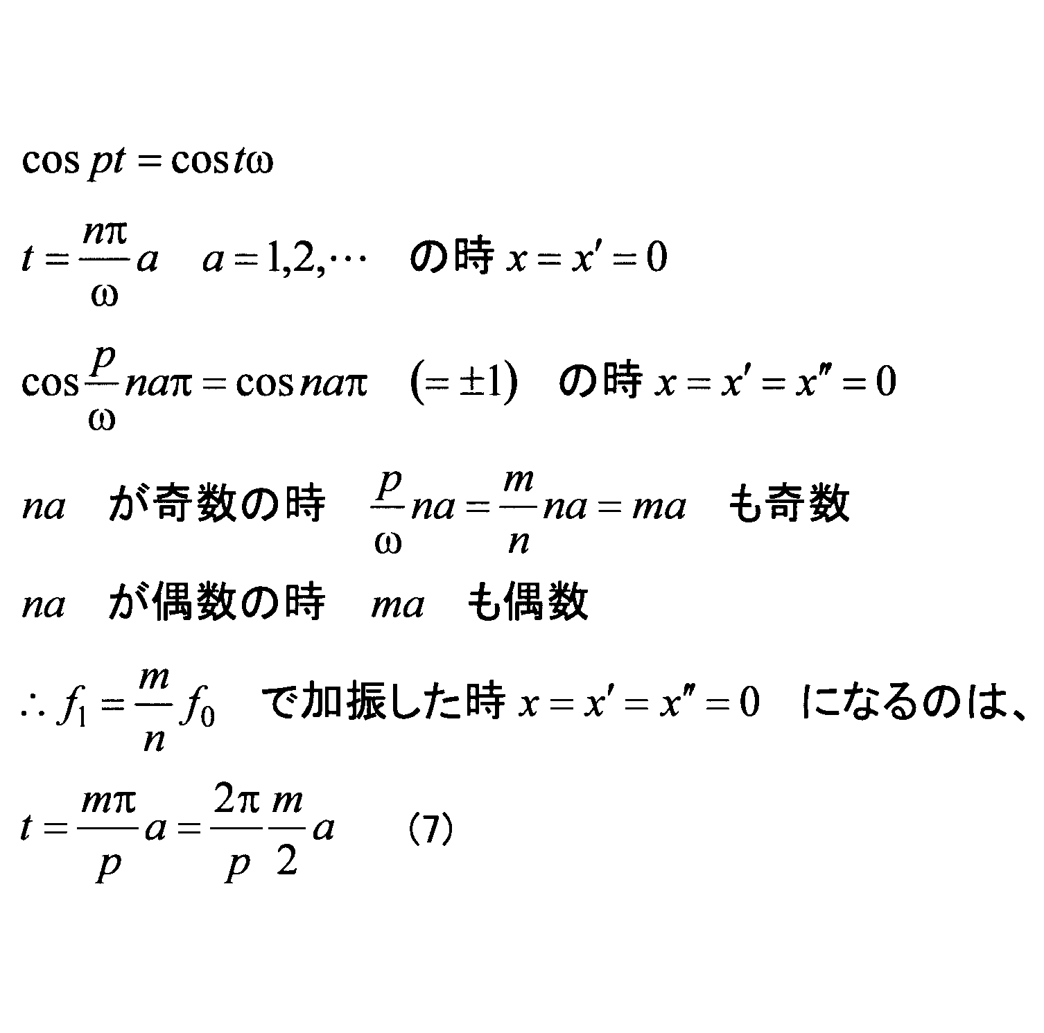
従って、naが奇数のときは、(p/ω)na=(m/n)naπ=maも奇数であることが必要になる。これとは逆に、naが偶数のときは、(p/ω)na=(m/n)naπ=maも偶数であることが必要になる。
このため、f1=(m/n)×f0で物体301を加振したときに、式(7)として示すt=(maπ/p)×a=(2π/p)×(m/2)×aが成り立つときに、変位xと加速度x''に加えて速度x'が0になる。
従って、式(7)から得られる条件は、aが偶数のときには、物体301をm回振動させるときである。これは、図14に示す条件と同様である。また、aが奇数であれば、n、mがともに偶数であり、かつ、物体301を(m/2)×a回振動させるときである。
また、変位xと加速度x''に加えて、式(5)に示す速度x'が0になる第2のケースは次式(8)として求まる。

ここで、(2k-1)はmが奇数であることを表し、(2l-1)はnが奇数であることを表す。
すなわち、t=(π/2p)×(2k-1)×a=(π/2ω)×(2l-1)×aが成り立つときに、cospt=costω=0が成り立つ。ただし、aは0以外の自然数である(a=1、2・・・)。これより、p=ω×(2k-1)/(2l-1)である。
従って、式(8)として示すf1={(2k-1)/(2l-1)}×f0、t=(2π/p)×{(2k-1)/4}×aが求まる。これは、物体301を(m/4)×a回振動させることを表す。
従って、式(8)から得られる条件は、n、mがともに奇数であり、かつ、物体301を周波数f1で(m/2)×a回振動させるときである。なお、この条件には、式(7)から求まる、aが奇数であれば、n、mがともに偶数であり、かつ、物体301を(m/2)×a回振動させるときという条件が含まれる。
以上より、変位xと加速度x''に加えて、式(5)に示す速度x'が0になるのは、aが偶数のときに周波数f1で物体301をm回振動させるときと、n、mがともに奇数であるときに物体301を周波数f1で(m/2)×a回振動させるときである。このうち、前者は図14に示す条件と同一であるため、ここでは新たに後者の条件が得られたことになる。後者の条件は、n、mがともに奇数であるときに物体301を周波数f1で(m/2)×a回振動させるときである。この条件につき、図17を用いて説明する。
図17は、n、mがともに奇数であるときに物体301を周波数f1で(m/2)×a回振動させたときの自由振動、強制振動、及び応答振動の変位、速度、及び加速度を示す図である。図17には、強制振動の周波数f1がf1=5/3×f0の場合(m=5、n=3)に、強制振動によって物体301を加振した場合の波形を示す。タイミング(1)、(2)は、それぞれ、5/2回と5回加振したタイミングである。
図17に示すように、5/2回加振したタイミング(1)において、応答振動の変位、速度、及び加速度は、すべて0になっている。また、5回加振したタイミング(2)においても、応答振動の変位、速度、及び加速度は、すべて0になっている。タイミング(2)は、図14に示す動作条件において、m、nが奇数である場合に相当する。
以上、実施の形態1によれば、n、mがともに正の奇数であるときに物体301を周波数f1(=(m/n)×f0)で(m/2)×a回振動させるときに、応答振動の変位、速度、及び加速度をすべて0にすることができる。ただし、aは、0以外の自然数であり、a=1、2・・・である。
従って、LRA140を駆動する駆動信号を表す波形データ240として、n、mがともに奇数であるときに周波数f1(=(m/n)×f0)で(m/2)×a回振動させる波形データをメモリ220に格納しておけば、タッチパネル120を操作したときに、LRA140により生じる振動によってクリック感を提示することができる。
図17に示すタイミング(1)で提示するクリック感は、タイミング(2)で提示するクリック感の半分の振動期間で実現されるため、より切れのあるクリック感を提示することができる。
図18は、強制振動の周波数と、振動時間との関係を示す図である。図18には、図17に示すタイミング(1)の動作点と、タイミング(2)の動作点とを示す。
上述のように、タイミング(1)で提示するクリック感は、タイミング(2)で提示するクリック感の半分の振動期間で実現される。このため、200Hzから500Hzの間で強制振動の周波数を設定する場合に、タイミング(1)の動作点は、タイミング(2)の動作点の間を補間するように得られる。特に、タイミング(2)の動作点は、高周波数側で離散的になるため、このようにタイミング(1)の動作点で補間されることは利点がある。
実際の電子機器100において、強制振動の周波数を設定する場合には、タッチパネル120の固有振動数、又は、動作点が高周波数側になる等の制約を考慮するため、実際に選択可能な動作点は限られる。
しかしながら、タイミング(2)の動作点の間を補間するようにタイミング(1)の動作点が得られるため、強制振動の周波数を設定する場合の選択肢が拡がるという効果がある。
ところで、LRA140の自由振動の減衰が比較的大きい場合には、上述のような駆動信号でタイミング(1)、(2)において、応答振動の変位、速度、及び加速度のうちのいずれかが0にならなくなる場合があり得る。
そこで、以下では、LRA140の自由振動の減衰を考慮して、応答振動の変位、速度、及び加速度のすべてが0になるようにする。
図19は、自由振動に比較的大きな減衰が存在する場合の自由振動、強制振動、及び応答振動の変位、速度、及び加速度を示す図である。
図19に示すLRA140の自由振動の変位xは、図16に示す自由振動(減衰なし)に比べて、時間経過に伴って減衰している。このため、速度x'及び加速度x''も時間経過に伴って減衰している。
このように自由振動に比較的大きい減衰が存在する場合には、例えば、タイミング(1)及び(2)において、応答振動の速度x'が0ではなくなる。これは、LRA140の自由振動に減衰があるが、強制振動は図16に示す波形と同様であるため、自由振動と強制振動を合成して得る応答振動の波形が図16に示す波形とは異なる波形になるためである。
減衰率は変位、速度、加速度で共通であるため、実施の形態1では、自由振動の減衰率を、自由振動の加速度に基づいて求める。ここで、減衰率を自由振動の加速度に基づいて求めるのは、自由振動の変位、速度、加速度のうち、加速度は加速度計で比較的簡単に測定できるからである。また、人間の感覚器の特性が加速度センサに合っているからである。例えば、図20に示す測定系400において、自由振動の加速度を求めることができる。
図20は、自由振動の加速度を測定する測定系400を示す図である。測定系400は、駆動部401、DA(Digital to Analog)コンバータ402、アンプ403、重り404、振動子405、加速度計406、及びスポンジ407を含む。
駆動部401は、所定の波形データを保持しており、波形データで表される駆動信号をDAコンバータ402に出力する。なお、所定の波形データは、強制振動を実現する波形データ240であることが望ましい。
重り404は、実際の電子機器100において図3に示すようにタッチパネル120にLRA140を取り付ける場合は、タッチパネル120と等しい重さの重りであればよい。なお、重り404の代わりに、実際にLRA140が取り付けられる部材を用いてもよい。図3に示すようにタッチパネル120にLRA140を取り付ける場合は、重り404の代わりにタッチパネル120を用いてもよい。
重り404の中心近傍には振動子405が取り付けられ、また、重り404には加速度計406が取り付けられる。重り404の端部は、スポンジ407を介して設置台等に設置される。
このような測定系400において、駆動部401から駆動信号をDAコンバータ402に出力し、DAコンバータ402でアナログ信号に変換された駆動信号は、アンプ403で増幅されて振動子405に入力される。振動子405は、例えば、LRAであればよい。
振動子405は、アンプ403から供給される駆動信号によって駆動され、重り404が振動する。そして、駆動信号をオフにした後に、加速度計406でLRA140の自由振動を測定すれば、LRA140の自由振動の減衰特性を求めることができる。
図21は、自由振動の加速度の減衰を示す図である。例えば、t=0秒で振動子405の駆動を開始し、t=0.04秒で駆動信号を停止すると、図21(A)に示すように、t=0.04秒以降は自由振動のみの波形が得られる。この自由振動の減衰を加速度計406で測定すれば、図21(A)に太線で示すような自由振動の減衰特性を表す包絡線410のデータを取得できる。なお、包絡線410は、例えば、ヒルベルト変換等を用いることによって求めることができる。
図21(A)に示す包絡線410は、h=e-σtで表される。ここで、-σは減衰率を表す係数であり、包絡線410を表す式(h=e-σt)は減衰特性を表す。
図21(A)に示す包絡線410を片対数で示すと、図21(B)の特性を得る。図21(B)に示す包絡線420の傾きは、-σである。
実施の形態1では、このようにして求まる減衰特性を応答振動の変位x、速度x'、及び加速度x''に乗じることにより、応答振動の変位x、速度x'、加速度x''がすべて0になる動作点を得る。
具体的には、駆動信号Z=Asin2πf1tに、減衰特性h=e-σtを乗じた駆動信号を表す波形データ240をメモリ220に格納し、この減衰特性を乗じた駆動信号を用いてLRA140を駆動する。
減衰特性を乗じた駆動信号Z1は、次式で表される。
Z1=A(e-σt)sin2πf1t
この駆動信号Z1を用いてLRA140を駆動した場合の応答振動の変位、速度、及び加速度は図22に示す通りである。
Z1=A(e-σt)sin2πf1t
この駆動信号Z1を用いてLRA140を駆動した場合の応答振動の変位、速度、及び加速度は図22に示す通りである。
図22は、駆動信号Z1でLRA140を駆動した場合の自由振動、強制振動、及び応答振動の変位、速度、及び加速度を示す図である。
図22に示すように、応答振動の変位x、速度x'、加速度x''は、タイミング(1)及び(2)の両方において、すべて0になっている。
図23は、減衰特性の有無による残留振動の違いを示す図である。図23には、m=5、n=4の場合の駆動信号による振動の加速度を示す。
図23(A)は、減衰特性を乗じていない駆動信号Z(=Asin2πf1t)を入力として、時刻t1で駆動信号Zをオフにした後に生じる自由振動の加速度を示す。
図23(B)は、減衰特性を乗じた駆動信号Z1(=A(e-σt)sin2πf1t)を入力として、時刻t1で駆動信号Z1をオフにした後に生じる自由振動の加速度を示す。
図23(A)と図23(B)を比べて分かるように、時刻t1以降において、図23(A)では比較的大きな残留振動が残るのに対して、図23(B)では残留振動が殆ど生じていないことが分かる。図23(B)における時刻t1以降の加速度は、0.02G以下であり、人間は感知できないレベルである。
以上、実施の形態1によれば、自由振動の減衰が比較的大きい場合においても、自由振動の減衰特性を表す減衰率を駆動信号に含ませることにより、応答振動の変位x、速度x'、加速度x''のすべてが0になるタイミングを確実に得ることができる。
従って、LRA140を駆動する駆動信号を表す波形データ240として、自由振動の減衰特性を表す減衰率を駆動信号を用いることにより、LRA140により生じる振動によってクリック感を提示することができる。
自由振動の減衰特性を表す減衰率を駆動信号に含ませる前の駆動信号としては、例えば、次の2つのいずれであってもよい。
LRA140の共振周波数をf0としたとき、f1=(m/n)×f0(m,nは、0以外の自然数かつm≠n)となる周波数f1の信号でLRA140をm回加振する信号を駆動信号を用いることができる。この場合は、図14に示す振動になる。
また、LRA140を駆動する駆動信号を表す波形データ240として、n、mがともに奇数であるときに周波数f1(=(m/n)×f0)で(m/2)×a回振動させる波形データを表す駆動信号を用いてもよい。この場合は、図17に示す振動になる。
なお、以上では、駆動信号が正弦波である形態について説明したが、駆動信号は正弦波に限られず、矩形波のような正弦波以外の波形であってもよい。
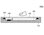
また実施の形態1の電子機器100では、LRA140がタッチパネル120の筐体側の面に取り付けられるものとしたが、これに限定されない。LRA140は、例えば筐体110内部に配置された基板150の近傍に配置されても良い。
図24は、LRA140が筐体に設けられた電子機器の例を示す図である。図24に示す電子機器100Aでは、LRA140が筐体110内部に設けられた基板150の近傍に配置されている。実施の形態1は、電子機器100Aに対しても適用することができる。また電子機器100Aに実施の形態1を適用した場合、実施の形態1の電子機器100と同様にメタルドーム式のボタン2を押下した際のクリック感を表現することができる。
以上では、残留振動を低減し得るLRA140の駆動条件として、次の4通りの駆動条件について説明した。
第1番目の駆動条件は、m,nが0以外の自然数であり、かつ、m≠nである場合に、LRA140の共振周波数f0に対して、f1=(m/n)×f0となる周波数f1を含む駆動信号でLRA140をm回加振する駆動条件である。
また、第2番目の駆動条件は、n、mが互いに異なる正の奇数である場合に、周波数f1=(m/n)×f0となる周波数f1を含む駆動信号でLRA140を(m/2)×a回振動させる駆動条件である。ただし、aは、0以外の自然数であり、a=1、2・・・である。
また、第3番目の駆動条件では、第1番目の駆動条件に対して、LRA140が実装される振動系の減衰率による減衰特性を乗じた駆動信号を用いる。すなわち、m,nが0以外の自然数であり、かつ、m≠nである場合に、LRA140の共振周波数f0に対して、f1=(m/n)×f0となる周波数f1を含む駆動信号に、LRA140が実装される振動系の減衰率による減衰特性を乗じた駆動信号で、LRA140をm回加振する駆動条件である。
また、第4番目の駆動条件では、第2番目の駆動条件に対して、LRA140が実装される振動系の減衰率による減衰特性を乗じた駆動信号を用いる。すなわち、n、mが互いに異なる正の奇数である場合に、LRA140の共振周波数f0に対して、周波数f1=(m/n)×f0となる周波数f1を含む駆動信号に、LRA140が実装される振動系の減衰率による減衰特性を乗じた駆動信号で、(m/2)×a回振動させる駆動条件である。ただし、aは、0以外の自然数であり、a=1、2・・・である。
しかしながら、LRA140の共振周波数が、加速度振幅に応じて変化する特性を有する場合には、上述の4通りの駆動信号では残留振動を低減しきれないおそれがある。共振周波数が、加速度振幅に応じて変化する特性とは、例えば、加速度振幅の増大に伴って、共振周波数が高周波数側にシフトする特性である。加速度振幅とは、加速度と同義であり、単位はm/s2又はG(Gravity)である。
このような特性は、漸硬ばねの非線形的な変形特性に類似している。図25は、漸硬ばねと線形ばねの変形特性を示す図である。図25において、横軸は変形量を表し、縦軸は漸硬ばねと線形ばねにかかる力を表す。なお、図25において、実線は漸硬ばねの変形特性を示し、破線は線形ばねの変形特性を示す。
図25に破線で示すように、線形ばねは、力の増大に伴って変形量が線形的に増大する。これに対して、漸硬ばねは、実線で示すように、力の増大に伴って変形量が少なくなる。このように、漸硬ばねは非線形的な変形特性を有する。
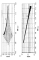
図26及び図27は、共振周波数が加速度振幅に応じて変化する特性を示す図である。ここでは、LRA140の共振周波数が、図26及び図27に示すように、加速度振幅に応じて変化する場合について説明する。LRA140がこのような特性を有するのは、例えば、LRA140の小型化に伴う薄型化等で、応力に対する変形量が線形的ではなく、非線形的になっているような場合である。
LRA140の共振周波数の定格値がf0である場合に、LRA140の駆動電圧を15V、35V、55V、75Vのいずれかに設定して周波数を変化させると、図26に示す周波数特性を得る。
周波数特性において加速度がピークを取る周波数が共振周波数である。図26に示すように、駆動電圧が高くなって加速度(加速度振幅)が大きくなるに伴い、周波数特性のピークが高周波数側にシフトしている。
図27は、図26の一部を拡大して示す図であり、駆動電圧が10V,15V,25V,35V,45V,55V,65V,75Vの場合の周波数特性を示す。図27に示すように、駆動電圧の増大によって加速度が増大するのに伴い、太い一点鎖線で示すように、共振周波数f0は高周波数側にシフトしている。
このように、加速度の増大に伴って共振周波数f0が高周波数側にシフトするのは、LRA140の漸硬ばねのような変形特性により、高周波数側で変形量が少なくなることによって、共振周波数が高くなるためと考えられる。
また、図27では、特に駆動電圧が55V以上の場合に、周波数が共振周波数を超えると、加速度が急激に低下している。これは、非線形振動のジャンプ現象であり、このようにある周波数を境に加速度の値が不連続的に飛んでおり、加速度が不定の状態が生じる。
ここで、例えば、LRA140の共振周波数の定格値が225Hzである場合に、実際には製造誤差等による共振周波数のずれが存在しうる。このため、図28を用いて、共振周波数f0を205Hz、210Hz、215Hz、225Hzにして、f1=(5/4)×f0で得られる周波数の駆動信号に、減衰特性を乗じた駆動信号を用いてLRA140を5回加振した場合の駆動信号と応答振動の変位について説明する。すなわち、図28には、上述した4通りの駆動条件のうちの第3番目の駆動条件において、m=5、n=4の場合に、共振周波数f0を205Hz、210Hz、215Hz、225Hzに設定して得られる応答振動の変位を示す。
図28は、LRA140の駆動信号の波形と応答振動の変位を示す図である。図28の(A)は共振周波数f0が205Hz、(B)は共振周波数f0が210Hz、(C)は共振周波数f0が215Hz、(D)は共振周波数f0が225Hzの場合の波形を示す。また、図28には、駆動信号の波形を破線で示し、応答振動の変位を実線で示す。なお、図28に示す応答振動の変位は、LRA140が加速度振幅に応じて共振周波数が変化する特性を有する場合のものである。また、図28に示す応答振動の変位は、LRA140を図3に示すようにタッチパネル120に取り付けた状態で得られるものである。
図28の(A)に示すように、時刻t1で205Hz×(5/4)の周波数で減衰特性を有する駆動信号を5周期にわたってLRA140に入力すると、駆動信号がオフになる時刻t2以後は、応答振動の変位は残留振動があることを示している。これは、応答振動の変位、速度、及び加速度が略ゼロになる点が生じないことを表している。
図28の(A)における時刻t2以後の応答振動の残留振動は、約0.02G以上の加速度があり、人間が知覚する強度の加速度である。このため、図28の(A)では、駆動信号をオフにした時刻t2以後において、人間に知覚可能な残留振動が生じており、クリック感を呈示することは難しい状況である。また、これは、図28の(B)、(C)、(D)においても同様である。
図28の(A)~(D)の中では、(B)の場合(210Hz×(5/4)の周波数で減衰特性を有する駆動信号を5周期にわたってLRA140に入力する場合)に残留振動が最も小さくなるが、図28の(B)の場合でも、駆動信号をオフにした時刻t2以後において、人間に知覚可能な残留振動が生じており、クリック感を呈示することは難しい状況である。
このように、LRA140の共振周波数が加速度振幅に応じて変化する特性を有する場合は、第3番目の駆動条件において共振周波数の定格値の誤差を考慮して上述のように調整を行っても、残留振動を人間が知覚不能なレベルにまで抑制できないおそれがある。
また、これは、上述の第1番目、第2番目、及び第4番目の駆動条件を用いた場合でも同様であると考えられ、上述の第1番目、第2番目、及び第4番目の駆動条件を用いて共振周波数を調整しても、残留振動を人間が知覚不能なレベルにまで抑制できないおそれがある。
このため、実施の形態1では、LRA140の共振周波数が加速度振幅に応じて変化する特性に基づいて駆動信号の周波数を時間経過に伴って変化させることにより、残留振動を人間が知覚不能なレベルにまで抑制する。以下、具体的な手法について説明する。
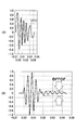
図29は、実施の形態1のLRA140の駆動制御方法による駆動信号の波形と応答振動の変位を示す図である。図29の(A)は、第3番目の駆動条件において210Hz×(5/4)の周波数で減衰特性を有する駆動信号を5周期にわたってLRA140に入力した場合の応答振動の変位を示す。図29の(A)に示す応答振動の変位は、図28の(B)に示す応答振動の変位と同一であり、LRA140の共振周波数が加速度振幅に応じて変化している。図29に示す応答振動の変位は、LRA140を図3に示すようにタッチパネル120に取り付けた状態で得られるものである。
図29の(A)では、時刻t1の直後と、時刻t2の直前のように応答振動の振幅が比較的小さい領域では、応答振動の周波数は約205Hzであり、応答振動の振幅が最大になる時刻t1Aの前後では、応答信号の周波数は約215Hzである。
これは、LRA140の共振周波数が、加速度振幅に応じて、205Hzから215Hzまで変化することを表している。
このため、実施の形態1のLRA140の駆動制御方法では、LRA140の駆動信号の周波数が、時刻tの変化に応じて205Hz~215Hz~205Hzと変化する特性q(t)を用いてLRA140の駆動制御を行う。
図29の(B)は、時刻tの変化に応じて、205Hz~215Hz~205Hzと周波数が変化する特性q(t)を用いて、f1=(5/4)×q(t)で与えられる駆動信号に減衰特性を乗じた駆動信号を用いてLRA140を5回加振した場合の駆動信号と応答振動の変位を示す。特性q(t)は、図29の(A)に示す応答振動の変位の周波数が、時刻t1での205Hzから、時刻t1Aでの215Hzまで上昇し、その後、時刻t2での205Hzまで低下するように変化する時間変化特性を有する。この特性q(t)については後述する。
図29の(B)に示すように、加速度振幅に応じて変化するLRA140の共振周波数に合わせた周波数の特性q(t)を用いた駆動信号でLRA140を駆動すると、駆動信号をオフにする時刻t2の直後では、応答振動の変位、速度、及び加速度が略ゼロになっており、時刻t2以後の加速度は約0.02G以下であり、人間が知覚できない強度の加速度である。
以上のように、実施の形態1では、LRA140の共振周波数が加速度振幅に応じて変化する特性に応じて、駆動信号の周波数を時間経過に伴って変化させて、LRA140の駆動制御を行う。
そして、このような駆動制御を行うことにより、残留振動を人間が知覚不能なレベルにまで抑制する。以下、特性q(t)を求める具体的な手法について説明する。
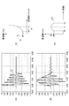
図30は、実施の形態1のLRA140の駆動信号を生成する方法を段階的に示す図(パート1)である。
まず、LRA140に正弦波状の駆動信号を入力して駆動し、LRA140の応答振動の加速度の定常振幅を計測する。正弦波状の駆動信号の周波数fは、LRA140の共振周波数の定格値、及び、定格値の前後の複数の値に設定し、複数の周波数で駆動した場合の応答振動の加速度の定常振幅を計測する。なお、応答振動の加速度の定常振幅は、LRA140を図3に示すようにタッチパネル120に取り付けた状態で計測する。
このように周波数の異なる複数種類の正弦波状の駆動信号をLRA140に入力して応答振動の加速度の定常振幅を計測することにより、図30の(A)に示すように、周波数fに対する応答振動の加速度の定常振幅の特性を得る。
例えば、LRA140の共振周波数の定格値が225Hzであり、共振周波数の誤差により、実際のLRA140の共振周波数が205Hz~235Hzの範囲で存在しうる場合には、一例として5Hz程度のマージンを取り、200Hz~240Hzの範囲で、複数の周波数fの正弦波状の駆動信号をLRA140に入力して応答振動の加速度の定常振幅を計測する。ここでは、誤差を考慮した共振周波数の範囲が205Hz~235Hzであり、さらにこの範囲にマージンを与えた範囲が200Hz~240Hzである。
例えば、200Hz~240Hzの範囲で、1Hzずつ周波数の異なる複数の周波数fの正弦波状の駆動信号をLRA140に入力して応答振動の加速度の定常振幅を計測することにより、図30の(A)に示すように、駆動信号の周波数fに対する加速度の特性を得る。図30の(A)に示す複数の点は、各周波数fで得られた応答振動の加速度の定常振幅を示す。
次に、図30の(A)に示す周波数fに対する応答振動の加速度の定常振幅を高次の多項式等で補間した曲線を求める。換言すれば、図30の(A)に示す複数の点に当てはまる曲線を表す式を求める。このようにして求まる曲線は、図30の(B)に示す曲線であり、この曲線は、周波数fの関数G(f)で表される。関数G(f)は、周波数fに対する応答振動の加速度の定常振幅の特性を表す。なお、周波数f11は、加速度Gをゼロ(G=0)にした場合の周波数であり、周波数f12は、LRA140を定格の最大電圧で駆動したときの加速度の定常振幅が最大となる周波数である。
次に、図30の(B)に示す曲線を表す関数G(f)の逆関数を求める。逆関数f(G)は、図30の(C)に示すように、横軸の加速度Gの変化に対して縦軸の周波数fが変化する特性として求まる。
次に、上述のようにして求めた逆関数G(f)を用いて、共振周波数f0を200Hzから240Hzまで変更しながら、特性q(t)と最良の共振周波数f0を求める。以下では、共振周波数f0を200Hzから240Hzまで変更しながら、ステップS1からステップS7を繰り返し実行する。200Hzから240Hzという共振周波数f0の範囲は、上述したように、共振周波数の誤差とマージン(5Hz)を考慮して求めた範囲である。
図31は、実施の形態1のLRA140の駆動信号を生成する方法を段階的に示す図(パート2)である。なお、以下ではLRA140を図3に示すようにタッチパネル120に取り付けた状態で駆動する。
まずステップS1では、上述の第1番目から第4番目のうちのいずれかの駆動条件を用いてLRA140を駆動する。ここでは、一例として、第3番目の駆動条件でLRA140を駆動することとする。また、ステップS1からステップS7の処理は繰り返し行うため、最初は共振周波数f0を200Hzに設定して第3番目の駆動条件でLRA140を駆動する。
第3番目の駆動条件は、m,nが0以外の自然数であり、かつ、m≠nである場合に、LRA140の共振周波数f0に対して、f1=(m/n)×f0となる周波数f1を含む駆動信号に、LRA140が実装される振動系の減衰率による減衰特性を乗じた駆動信号で、LRA140をm回加振する駆動条件である。
第3番目の駆動条件による駆動信号は、周波数f1と減衰率σを用いて、Z1=A(e-σt)sin2πf1tと表される。この駆動信号Z1は、図31の(A)に示すような波形を有する。
次に、ステップS2として、図31の(A)に示す駆動信号Z1でLRA140を駆動することによって得られる応答振動の加速度を計測する。応答振動の加速度は、図31の(B)に示す波形で表される。
応答振動の加速度の計測は、例えば、加速度計を用いて、時刻t= [t0, …,ti, … tn]において測定した値をデジタル変換することにより、離散的なデジタル値の加速度a= [a0, …,ai, … an]として求めることができる。この加速度のデータは、時系列的な離散値である。
次に、ステップS3として、加速度a= [a0, …,ai, … an]に対してヒルベルト変換を行うことにより、加速度の包絡線のデータw= [w0, …,wi, … wn]を求める。加速度の包絡線のデータwは、図31の(B)に破線で示す包絡線を表す時系列的な離散値であり、加速度の最大値を結ぶ包絡線を表す。
次に、ステップS4として、加速度の包絡線のデータw= [w0, …,wi, … wn]を、図30の(C)に示す逆関数f(G)に代入し、図31の(C)に示す周波数の時系列データb=[b0,…,bi,…bn]を得る。包絡線のデータの各値(w0 ~ wn)は加速度を表すため、逆関数f(G)の加速度Gに代入することができる。
次に、ステップS5として、時刻t= [t0, …,ti, … tn]と、周波数の時系列データb=[b0,…,bi,…bn]との対応を求め、高次多項式等で補間すると、図31の(D)に示す特性q(t)を得る。特性q(t)は、図31の(D)に示す特性を表す。特性q(t)は、図29の(A)に示すLRA140の共振周波数が時間の経過に応じて変化する時間特性を表す。共振周波数が加速度振幅に応じて変化するLRA140を駆動すると、時間変化に応じて加速度が変化するため、時間の経過に応じて共振周波数が変化する。特性q(t)は、このように共振周波数が時間の経過に応じて変化する時間特性を表す。
図32は、実施の形態1のLRA140の駆動信号を生成する方法を段階的に示す図(パート3)である。以下ではLRA140を図3に示すようにタッチパネル120に取り付けた状態で駆動する。
次に、ステップS6として、駆動信号Z1=A(e-σt)sin2πf1tのf1に含まれるf0をq(t)に入れ替えることにより、駆動信号Z2(t)を得る。駆動信号Z2(t)は図32の(A)に示す通りであり、次式で表される。
Z2(t)=A(e-σt)sin2π(m/n)q(t)t
次に、ステップS7として、駆動信号Z2(t)を用いてLRA140を駆動し、図32の(B)に示す残留振動の振幅をerrorとして計測する。
Z2(t)=A(e-σt)sin2π(m/n)q(t)t
次に、ステップS7として、駆動信号Z2(t)を用いてLRA140を駆動し、図32の(B)に示す残留振動の振幅をerrorとして計測する。
そして、f0を変えて、ステップS1からS7を繰り返し行い、残留振動の振幅errorを計測する。ステップS1からS7の処理を繰り返し行うことにより、複数のf0についての残留振動の振幅errorが計測される。
例えば、f0=200Hzに対応する特性q(t)を含む駆動信号Z2(t)でLRA140を駆動したときの残留振動の振幅errorが0.05Gであったとする。また、f0=201Hzに対応する特性q(t)を含む駆動信号Z2(t)でLRA140を駆動したときの残留振動の振幅errorが0.04Gであったとする。
このように、f0を1Hzずつ変化させて残留振動の振幅errorを求めて行き、f0=210Hzに対応する特性q(t)を含む駆動信号Z2(t)でLRA140を駆動したときの残留振動の振幅errorが0.01Gであり、f0=240Hzに対応する特性q(t)を含む駆動信号Z2(t)でLRA140を駆動したときの残留振動の振幅errorが0.05Gであったとする。
このような場合には、f0=210Hzに対応する特性q(t)を含む駆動信号Z2(t)でLRA140を駆動したときの残留振動の振幅errorが0.01Gで最小であるため、最良の共振周波数f0は210Hzと求まる。最良の共振周波数f0は周波数f2の一例である。周波数f2は、誤差を考慮した共振周波数f0の範囲に含まれる周波数である。
このように残留振動の振幅errorが人間の感知下限である0.02G以下になるのは、応答振動の変位x、速度x'、加速度x''のすべてが0になっているからである。
実施の形態1の駆動制御装置では、以上のようにして、残留振動の振幅errorが最小になる共振周波数f0を求める。
そして、上述のようにして求まる最良の共振周波数f0を用いてLRA140を駆動すれば、残留振動の振幅を人間が感知することはなく、良好なクリック感を提示することができる。
従って、実施の形態1によれば、LRA140の共振周波数が加速度振幅に応じて変化する特性を有する場合においても、LRA140の共振周波数が時間経過に応じて変化する時間特性q(t)を駆動信号Z1に代入することにより、応答振動の変位x、速度x'、加速度x''のすべてが0になるタイミングを確実に得ることができる。
従って、LRA140を駆動する駆動信号を表す波形データ240として、LRA140の共振周波数が時間経過に応じて変化する時間特性q(t)を用いることにより、LRA140により生じる振動によってクリック感を提示することができる。
なお、LRA140の共振周波数が時間経過に応じて変化する時間特性q(t)を表すデータは、離散的な数値データであり、波形データ240(図5参照)としてメモリ220に格納しておけばよい。
また、以上では、残留振動を低減し得るLRA140の駆動方法として、第1番目から第4番目の駆動条件で、LRA140の共振周波数が時間経過に応じて変化する時間特性(q(t))を求める形態について説明した。しかしながら、第1番目から第4番目の駆動条件以外の駆動条件による駆動信号を用いて、LRA140の共振周波数が時間経過に応じて変化する時間特性(q(t))を求めて、LRA140を駆動するようにしてもよい。
また、以上では、応答振動の加速度の包絡線のデータ(図31(B)参照)から時間特性q(t)を求めたが、時間特性q(t)の求め方はこのような手法に限られない。時間特性q(t)は、例えば、図31(B)の応答振動の変位を正弦波で近似することによって求めてもよい。
<実施の形態2>
以下に図面を参照して実施の形態2について説明する。実施の形態2では、LRA140の共振周波数f0を電子機器100に組み込んだ状態で測定した値とする例である。実施の形態2の説明では、実施の形態1との相違点についてのみ説明する。また実施の形態2において、実施の形態1と同様の機能を有するものには実施の形態1の説明で用いた符号と同様の符号を付与し、その説明を省略する。
以下に図面を参照して実施の形態2について説明する。実施の形態2では、LRA140の共振周波数f0を電子機器100に組み込んだ状態で測定した値とする例である。実施の形態2の説明では、実施の形態1との相違点についてのみ説明する。また実施の形態2において、実施の形態1と同様の機能を有するものには実施の形態1の説明で用いた符号と同様の符号を付与し、その説明を省略する。
実施の形態2では、LRA140を電子機器100に組み込んだ状態におけるタッチパネル120の共振周波数f0′を測定する。そして実施の形態2では、駆動信号Zの周波数f1を算出する際に共振周波数f0′を用いる。
図33は、実施の形態2の駆動装置を説明する図である。実施の形態2の駆動装置200Aは、CPU210Aと、メモリ220Aとを有する。
CPU210は、メモリ220Aから後述する周波数測定プログラム255を読み出して実行することで、後述する共振周波数f0′の測定と再設定を行う。
メモリ220Aには、駆動制御プログラム230、波形データ240、API250に加え、周波数測定プログラム255、設計値データ256が格納されている。
周波数測定プログラム255は、例えばLRA140が電子機器100に組み込まれた状態でのLRA140の共振周波数f0′の測定処理をCPU210に実行させる。設計値データ256は、電子機器100が設計された際に決められた値である。実施の形態2の設計値データ256は、例えばLRA140固有の共振周波数f0である。
以下に実施の形態2における共振周波数f0′の測定について説明する。
図34は、実施の形態2における共振周波数の測定処理を説明するフローチャートである。
実施の形態2において、電子機器100に対して共振周波数f0′の測定指示がなされると(ステップS1701)、CPU0210は周波数測定プログラム255を読み出す。実施の形態2において共振周波数f0′の測定指示がなされるときとは、例えば電子機器100の製造工程においてLRA140とタッチパネル120を筐体110に組み込む工程が終了したときや、工場出荷時等である。
周波数測定プログラム255は、CPU210に、LRA140に対して所定の周波数の帯域において複数の周波数の正弦波を駆動信号として印加させる(ステップS1702)。具体的には例えばCPU210は、100Hzから300Hzにおいて、周波数100Hzの正弦波、周波数110Hzの正弦波、・・・、周波数290Hzの正弦波、周波数300Hzの正弦波というように、LRA140に駆動信号を印加する。
周波数測定プログラム255は、CPU210に、周波数の異なる駆動信号毎の
タッチパネル120の振動の加速度の最大値をメモリ220Aに格納させる(ステップS1703)。具体的には電子機器100は、図示しない加速度センサが内蔵されており、周波数の異なる駆動信号がLRA140に印加される度にタッチパネル120の振動の加速度の最大値を検出する。メモリ220は、周波数測定プログラム255による演算結果を記憶する領域が設けられており、この領域に駆動信号毎の加速度の最大値が一時的に格納される。
タッチパネル120の振動の加速度の最大値をメモリ220Aに格納させる(ステップS1703)。具体的には電子機器100は、図示しない加速度センサが内蔵されており、周波数の異なる駆動信号がLRA140に印加される度にタッチパネル120の振動の加速度の最大値を検出する。メモリ220は、周波数測定プログラム255による演算結果を記憶する領域が設けられており、この領域に駆動信号毎の加速度の最大値が一時的に格納される。
続いて周波数測定プログラム255は、CPU210に、メモリ220Aに格納された加速度のうち、加速度が最大となる駆動信号の周波数を選択させる(ステップS1704)。続いて周波数測定プログラム255は、選択した駆動信号の周波数を共振周波数f0′とし、CPU210に、メモリ220Aの設計値データ256を共振周波数f0′に上書きさせる(ステップS1705)。
実施の形態2では、この処理により共振周波数をf0からf0′へ変更する。したがって実施の形態2では、残留振動を抑制するための駆動信号の周波数f1は、f1=(m/n)×f0′となる。
よって実施の形態2では、例えばLRA140にタッチパネル120や筐体110等の振動が重畳されるような場合に、直接ユーザの指に触れるタッチパネル120の共振周波数f0′に基づき駆動信号f1を算出することができる。このため実施の形態2では、ユーザに対して1~数周期で急速に減衰する短時間の波形の触感を直接提供することができ、クリック感を表現することができる。
尚実施の形態2では、共振周波数f0′を周波数測定プログラム255により行うものとしたが、共振周波数f0′は電子機器100の外部で測定され、メモリ220Aの設計値データ256に上書きされても良い。
また実施の形態2は、電子機器100Aにも適用することができる。
以上、実施の形態の駆動装置、電子機器、駆動制御プログラム、及び駆動信号の生成方法について詳述したが、特定の実施の形態に限定されるものではなく、特許請求の範囲に記載された範囲内において、種々の変形及び変更が可能である。
100、100A 電子機器
110 筐体
120 タッチパネル
130 両面テープ
140 LRA
200 駆動装置
210 CPU
220 メモリ
230 駆動制御プログラム
240 波形データ
250 API
255 周波数測定プログラム
256 設計値データ
260 ドライバIC
110 筐体
120 タッチパネル
130 両面テープ
140 LRA
200 駆動装置
210 CPU
220 メモリ
230 駆動制御プログラム
240 波形データ
250 API
255 周波数測定プログラム
256 設計値データ
260 ドライバIC
Claims (7)
- 共振周波数の定格値がf0である振動生成装置であって、前記共振周波数が加速度振幅に応じて前記定格値f0を含む第1共振周波数から第2共振周波数の範囲で変化する周波数特性を有する振動生成装置を、前記共振周波数の時間特性q(t)に対して、周波数f1=(m/n)×q(t)(m,nは互いに異なる0以外の自然数)を満たす正弦波であり、且つ前記振動生成装置をm回加振する第1駆動信号、又は、周波数f1=(m/n)×q(t)(m,nは互いに異なる正の奇数)を満たす正弦波であり、且つ前記振動生成装置を(m/2)×a(aは0以外の自然数)回加振する第2駆動信号を表す波形データが格納された記憶部と、
前記記憶部に格納された前記波形データを読み出し、前記波形データに対応する前記第1駆動信号又は前記第2駆動信号を前記振動生成装置へ出力する駆動処理部と、
を含み、
前記時間特性q(t)は、誤差を考慮した前記共振周波数の範囲に含まれる周波数f2に対して、周波数f1=(m/n)×f2(m,nは互いに異なる0以外の自然数)を満たす正弦波であり、且つ前記振動生成装置をm回加振する第3駆動信号、又は、周波数f1=(m/n)×f2(m,nは互いに異なる正の奇数)を満たす正弦波であり、且つ前記振動生成装置を(m/2)×a(aは0以外の自然数)回加振する第4駆動信号で前記振動生成装置を駆動したときに得られる、前記振動生成装置の共振周波数が時間経過に応じて変化する時間特性である、駆動装置。 - 前記時間特性q(t)は、前記振動生成装置の前記共振周波数の加速度振幅に対する周波数特性に、前記第3駆動信号又は前記第4駆動信号で前記振動生成装置を駆動することによって得られる応答振動の変位の加速度の包絡線を表す加速度を代入することによって得る、前記振動生成装置の共振周波数が時間経過に応じて変化する時間特性である、請求項1記載の駆動装置。
- 前記記憶部に格納される前記波形データは、前記第1駆動信号又は前記第2駆動信号に、前記振動生成装置が実装される振動系の減衰率による減衰特性を乗じて得る駆動信号を表す波形データである、請求項1又は2記載の駆動装置。
- 前記周波数f1は、f1=(m/n)×f0(m,nは0以外の自然数かつm>n)を満たす、請求項1乃至3のいずれか一項記載の駆動装置。
- タッチパネルと、
共振周波数の定格値がf0である振動生成装置であって、前記共振周波数が加速度振幅に応じて前記定格値f0を含む第1共振周波数から第2共振周波数の範囲で変化する周波数特性を有し、前記タッチパネルを振動させる振動生成装置と、
前記振動生成装置を、前記共振周波数の時間特性q(t)に対して、周波数f1=(m/n)×q(t)(m,nは互いに異なる0以外の自然数)を満たす正弦波であり、且つ前記振動生成装置をm回加振する第1駆動信号、又は、周波数f1=(m/n)×q(t)(m,nは互いに異なる正の奇数)を満たす正弦波であり、且つ前記振動生成装置を(m/2)×a(aは0以外の自然数)回加振する第2駆動信号を表す波形データが格納された記憶部と、前記記憶部に格納された前記波形データを読み出し、前記波形データに対応する前記第1駆動信号又は前記第2駆動信号を前記振動生成装置へ出力する駆動処理部とを有する駆動装置と
を含み、
前記時間特性q(t)は、誤差を考慮した前記共振周波数の範囲に含まれる周波数f2に対して、周波数f1=(m/n)×f2(m,nは互いに異なる0以外の自然数)を満たす正弦波であり、且つ前記振動生成装置をm回加振する第3駆動信号、又は、周波数f1=(m/n)×f2(m,nは互いに異なる正の奇数)を満たす正弦波であり、且つ前記振動生成装置を(m/2)×a(aは0以外の自然数)回加振する第4駆動信号で前記振動生成装置を駆動したときに得られる、前記振動生成装置の共振周波数が時間経過に応じて変化する時間特性である、電子機器。 - 共振周波数の定格値がf0である振動生成装置であって、前記共振周波数が加速度振幅に応じて前記定格値f0を含む第1共振周波数から第2共振周波数の範囲で変化する周波数特性を有する振動生成装置を、前記共振周波数の時間特性q(t)に対して、周波数f1=(m/n)×q(t)(m,nは互いに異なる0以外の自然数)を満たす正弦波であり、且つ前記振動生成装置をm回加振する第1駆動信号、又は、周波数f1=(m/n)×q(t)(m,nは互いに異なる正の奇数)を満たす正弦波であり、且つ前記振動生成装置を(m/2)×a(aは0以外の自然数)回加振する第2駆動信号を表す波形データを読み出し、
前記波形データに対応する前記第1駆動信号又は前記第2駆動信号を前記振動生成装置へ出力する、
処理をコンピュータに実行させるプログラムであって、
前記時間特性q(t)は、誤差を考慮した前記共振周波数の範囲に含まれる周波数f2に対して、周波数f1=(m/n)×f2(m,nは互いに異なる0以外の自然数)を満たす正弦波であり、且つ前記振動生成装置をm回加振する第3駆動信号、又は、周波数f1=(m/n)×f2(m,nは互いに異なる正の奇数)を満たす正弦波であり、且つ前記振動生成装置を(m/2)×a(aは0以外の自然数)回加振する第4駆動信号で前記振動生成装置を駆動したときに得られる、前記振動生成装置の共振周波数が時間経過に応じて変化する時間特性である、駆動制御プログラム。 - 共振周波数の定格値がf0である振動生成装置であって、前記共振周波数が加速度振幅に応じて前記定格値f0を含む第1共振周波数から第2共振周波数の範囲で変化する周波数特性を有する振動生成装置を、誤差を考慮した前記共振周波数の範囲に含まれる周波数f2に対して、周波数f1=(m/n)×f2(m,nは互いに異なる0以外の自然数)を満たす正弦波であり、且つ前記振動生成装置をm回加振する第1駆動信号、又は、周波数f1=(m/n)×f2(m,nは互いに異なる正の奇数)を満たす正弦波であり、且つ前記振動生成装置を(m/2)×a(aは0以外の自然数)回加振する第2駆動信号で前記振動生成装置を駆動したときに得られる、前記振動生成装置の共振周波数が時間経過に応じて変化する時間特性q(t)を求める段階と、
前記共振周波数の時間特性q(t)に対して、周波数f1=(m/n)×q(t)(m,nは互いに異なる0以外の自然数)を満たす正弦波であり、且つ前記振動生成装置をm回加振する第3駆動信号、又は、周波数f1=(m/n)×q(t)(m,nは互いに異なる正の奇数)を満たす正弦波であり、且つ前記振動生成装置を(m/2)×a(aは0以外の自然数)回加振する第4駆動信号を表す波形データを生成する段階と
を含む、駆動信号の生成方法。
Priority Applications (4)
| Application Number | Priority Date | Filing Date | Title |
|---|---|---|---|
| CN201380081126.XA CN105745031A (zh) | 2013-12-06 | 2013-12-06 | 驱动装置、电子设备、驱动控制程序、以及驱动信号的生成方法 |
| PCT/JP2013/082803 WO2015083283A1 (ja) | 2013-12-06 | 2013-12-06 | 駆動装置、電子機器、駆動制御プログラム、及び駆動信号の生成方法 |
| JP2015551354A JP6142928B2 (ja) | 2013-12-06 | 2013-12-06 | 駆動装置、電子機器、駆動制御プログラム、及び駆動信号の生成方法 |
| US15/139,465 US9684377B2 (en) | 2013-12-06 | 2016-04-27 | Drive apparatus, electronic device, drive control program, and drive signal generating method |
Applications Claiming Priority (1)
| Application Number | Priority Date | Filing Date | Title |
|---|---|---|---|
| PCT/JP2013/082803 WO2015083283A1 (ja) | 2013-12-06 | 2013-12-06 | 駆動装置、電子機器、駆動制御プログラム、及び駆動信号の生成方法 |
Related Child Applications (1)
| Application Number | Title | Priority Date | Filing Date |
|---|---|---|---|
| US15/139,465 Continuation US9684377B2 (en) | 2013-12-06 | 2016-04-27 | Drive apparatus, electronic device, drive control program, and drive signal generating method |
Publications (1)
| Publication Number | Publication Date |
|---|---|
| WO2015083283A1 true WO2015083283A1 (ja) | 2015-06-11 |
Family
ID=53273075
Family Applications (1)
| Application Number | Title | Priority Date | Filing Date |
|---|---|---|---|
| PCT/JP2013/082803 Ceased WO2015083283A1 (ja) | 2013-12-06 | 2013-12-06 | 駆動装置、電子機器、駆動制御プログラム、及び駆動信号の生成方法 |
Country Status (4)
| Country | Link |
|---|---|
| US (1) | US9684377B2 (ja) |
| JP (1) | JP6142928B2 (ja) |
| CN (1) | CN105745031A (ja) |
| WO (1) | WO2015083283A1 (ja) |
Cited By (4)
| Publication number | Priority date | Publication date | Assignee | Title |
|---|---|---|---|---|
| JP2019149152A (ja) * | 2018-01-26 | 2019-09-05 | イマージョン コーポレーションImmersion Corporation | アクチュエーターモデルに基づいてアクチュエーター制御を行う方法及びデバイス |
| JP2019147147A (ja) * | 2018-02-27 | 2019-09-05 | 国立大学法人埼玉大学 | 皮膚感覚提示装置、超音波変調装置及び超音波変調方法 |
| EP4198695A1 (en) | 2021-12-17 | 2023-06-21 | Alps Alpine Co., Ltd. | Vibration generator and vibration generating method |
| JP2024062754A (ja) * | 2022-10-25 | 2024-05-10 | アルプスアルパイン株式会社 | 触覚提示装置、及び、触覚提示方法 |
Families Citing this family (42)
| Publication number | Priority date | Publication date | Assignee | Title |
|---|---|---|---|---|
| US11152882B2 (en) * | 2015-02-13 | 2021-10-19 | Resonant Systems, Inc. | Oscillating-resonant-module controller |
| CN105978288B (zh) * | 2016-06-14 | 2018-09-07 | 瑞声声学科技(常州)有限公司 | 线性电机系统 |
| US10732714B2 (en) * | 2017-05-08 | 2020-08-04 | Cirrus Logic, Inc. | Integrated haptic system |
| US11259121B2 (en) | 2017-07-21 | 2022-02-22 | Cirrus Logic, Inc. | Surface speaker |
| CN108325806B (zh) * | 2017-12-29 | 2020-08-21 | 瑞声科技(新加坡)有限公司 | 振动信号的生成方法及装置 |
| US10455339B2 (en) | 2018-01-19 | 2019-10-22 | Cirrus Logic, Inc. | Always-on detection systems |
| US10620704B2 (en) | 2018-01-19 | 2020-04-14 | Cirrus Logic, Inc. | Haptic output systems |
| US11139767B2 (en) | 2018-03-22 | 2021-10-05 | Cirrus Logic, Inc. | Methods and apparatus for driving a transducer |
| US10795443B2 (en) | 2018-03-23 | 2020-10-06 | Cirrus Logic, Inc. | Methods and apparatus for driving a transducer |
| US10820100B2 (en) | 2018-03-26 | 2020-10-27 | Cirrus Logic, Inc. | Methods and apparatus for limiting the excursion of a transducer |
| US10832537B2 (en) | 2018-04-04 | 2020-11-10 | Cirrus Logic, Inc. | Methods and apparatus for outputting a haptic signal to a haptic transducer |
| US11069206B2 (en) | 2018-05-04 | 2021-07-20 | Cirrus Logic, Inc. | Methods and apparatus for outputting a haptic signal to a haptic transducer |
| US10936068B2 (en) * | 2018-06-15 | 2021-03-02 | Immersion Corporation | Reference signal variation for generating crisp haptic effects |
| US11269415B2 (en) | 2018-08-14 | 2022-03-08 | Cirrus Logic, Inc. | Haptic output systems |
| GB201817495D0 (en) | 2018-10-26 | 2018-12-12 | Cirrus Logic Int Semiconductor Ltd | A force sensing system and method |
| US12176781B2 (en) | 2019-03-29 | 2024-12-24 | Cirrus Logic Inc. | Methods and systems for estimating transducer parameters |
| US10828672B2 (en) | 2019-03-29 | 2020-11-10 | Cirrus Logic, Inc. | Driver circuitry |
| US10955955B2 (en) | 2019-03-29 | 2021-03-23 | Cirrus Logic, Inc. | Controller for use in a device comprising force sensors |
| US10726683B1 (en) | 2019-03-29 | 2020-07-28 | Cirrus Logic, Inc. | Identifying mechanical impedance of an electromagnetic load using a two-tone stimulus |
| US11644370B2 (en) | 2019-03-29 | 2023-05-09 | Cirrus Logic, Inc. | Force sensing with an electromagnetic load |
| US10992297B2 (en) | 2019-03-29 | 2021-04-27 | Cirrus Logic, Inc. | Device comprising force sensors |
| US11509292B2 (en) | 2019-03-29 | 2022-11-22 | Cirrus Logic, Inc. | Identifying mechanical impedance of an electromagnetic load using least-mean-squares filter |
| US12035445B2 (en) | 2019-03-29 | 2024-07-09 | Cirrus Logic Inc. | Resonant tracking of an electromagnetic load |
| US10976825B2 (en) | 2019-06-07 | 2021-04-13 | Cirrus Logic, Inc. | Methods and apparatuses for controlling operation of a vibrational output system and/or operation of an input sensor system |
| US11150733B2 (en) | 2019-06-07 | 2021-10-19 | Cirrus Logic, Inc. | Methods and apparatuses for providing a haptic output signal to a haptic actuator |
| WO2020254788A1 (en) | 2019-06-21 | 2020-12-24 | Cirrus Logic International Semiconductor Limited | A method and apparatus for configuring a plurality of virtual buttons on a device |
| JP7360281B2 (ja) * | 2019-09-10 | 2023-10-12 | 株式会社東海理化電機製作所 | 制御装置、制御方法、及びプログラム |
| JP2021043619A (ja) * | 2019-09-10 | 2021-03-18 | 株式会社東海理化電機製作所 | 制御装置、制御方法、およびプログラム |
| US11408787B2 (en) | 2019-10-15 | 2022-08-09 | Cirrus Logic, Inc. | Control methods for a force sensor system |
| US11380175B2 (en) | 2019-10-24 | 2022-07-05 | Cirrus Logic, Inc. | Reproducibility of haptic waveform |
| US12276687B2 (en) | 2019-12-05 | 2025-04-15 | Cirrus Logic Inc. | Methods and systems for estimating coil impedance of an electromagnetic transducer |
| US11545951B2 (en) | 2019-12-06 | 2023-01-03 | Cirrus Logic, Inc. | Methods and systems for detecting and managing amplifier instability |
| US12244253B2 (en) | 2020-04-16 | 2025-03-04 | Cirrus Logic Inc. | Restricting undesired movement of a haptic actuator |
| US11662821B2 (en) | 2020-04-16 | 2023-05-30 | Cirrus Logic, Inc. | In-situ monitoring, calibration, and testing of a haptic actuator |
| KR102836011B1 (ko) * | 2020-08-31 | 2025-07-18 | 알프스 알파인 가부시키가이샤 | 입력 장치 |
| JP7553404B2 (ja) * | 2021-05-11 | 2024-09-18 | アルプスアルパイン株式会社 | 入力装置 |
| CN115389927B (zh) * | 2021-05-24 | 2024-05-10 | 荣耀终端有限公司 | 马达阻尼的测算方法和系统 |
| US11933822B2 (en) | 2021-06-16 | 2024-03-19 | Cirrus Logic Inc. | Methods and systems for in-system estimation of actuator parameters |
| US11765499B2 (en) | 2021-06-22 | 2023-09-19 | Cirrus Logic Inc. | Methods and systems for managing mixed mode electromechanical actuator drive |
| US11908310B2 (en) | 2021-06-22 | 2024-02-20 | Cirrus Logic Inc. | Methods and systems for detecting and managing unexpected spectral content in an amplifier system |
| US12481365B2 (en) | 2021-07-01 | 2025-11-25 | Mitsubishi Electric Corporation | Tactile sense presentation device and tactile sense presentation method |
| US11552649B1 (en) | 2021-12-03 | 2023-01-10 | Cirrus Logic, Inc. | Analog-to-digital converter-embedded fixed-phase variable gain amplifier stages for dual monitoring paths |
Citations (5)
| Publication number | Priority date | Publication date | Assignee | Title |
|---|---|---|---|---|
| JP2002149312A (ja) * | 2000-08-08 | 2002-05-24 | Ntt Docomo Inc | 携帯型電子機器、電子機器、振動発生器、振動による報知方法および報知制御方法 |
| JP2008521597A (ja) * | 2004-11-30 | 2008-06-26 | イマージョン コーポレイション | 振動触覚ハプティック効果を発生させるための共振装置を制御するためのシステムおよび方法 |
| JP2010506499A (ja) * | 2006-10-05 | 2010-02-25 | イマーション コーポレーション | 多重モード触覚フィードバックシステム |
| JP2010287232A (ja) * | 2009-06-09 | 2010-12-24 | Immersion Corp | アクチュエータを用い触覚効果を生成する方法及び装置 |
| JP2011501296A (ja) * | 2007-10-17 | 2011-01-06 | イマージョン コーポレイション | 触覚フィードバック装置用のデジタルエンベロープ変調器 |
Family Cites Families (14)
| Publication number | Priority date | Publication date | Assignee | Title |
|---|---|---|---|---|
| DE3172071D1 (en) * | 1980-11-28 | 1985-10-03 | Casio Computer Co Ltd | Envelope control system for electronic musical instrument |
| US6020876A (en) * | 1997-04-14 | 2000-02-01 | Immersion Corporation | Force feedback interface with selective disturbance filter |
| US6448670B1 (en) * | 1998-05-12 | 2002-09-10 | Alps Electric Co., Ltd. | Signal input device |
| US7113876B2 (en) * | 2004-09-08 | 2006-09-26 | Sentech Biomed Corporation | Technique and electronic circuitry for quantifying a transient signal using threshold-crossing counting to track signal amplitude |
| EP2380640A3 (en) * | 2005-06-27 | 2011-12-28 | Coactive Drive Corporation | Synchronized vibration device for haptic feedback |
| US8120585B2 (en) * | 2006-11-16 | 2012-02-21 | Nokia Corporation | Method, apparatus, and computer program product providing vibration control interface |
| US8098234B2 (en) * | 2007-02-20 | 2012-01-17 | Immersion Corporation | Haptic feedback system with stored effects |
| KR100885416B1 (ko) * | 2007-07-19 | 2009-02-24 | 건국대학교 산학협력단 | 일체형 가속도계·각속도계 구동 시스템 |
| GB0724149D0 (en) | 2007-12-11 | 2008-01-23 | New Transducers Ltd | Touch-sensitive device |
| US10401961B2 (en) * | 2009-06-09 | 2019-09-03 | Immersion Corporation | Method and apparatus for generating haptic effects using actuators |
| KR101177610B1 (ko) * | 2009-09-29 | 2012-08-28 | 삼성전기주식회사 | 터치스크린장치 |
| KR101642149B1 (ko) * | 2010-01-05 | 2016-07-25 | 삼성전자주식회사 | 터치스크린을 구비한 휴대용 단말기의 햅틱 피드백 제어 방법 및 장치 |
| ES2398113B1 (es) * | 2011-05-11 | 2014-01-27 | Universidad Politécnica De Valencia | DISPOSITIVO AWG (Arrayed Waveguide Grating) PARA LA MULTIPLEXACIÓN Y DEMULTIPLEXACIÓN DE SEÑALES SINTONIZABLE Y MÉTODO DE SINTONIZACIÓN DE DICHO DISPOSITIVO |
| CN103870060B (zh) * | 2012-12-13 | 2017-09-12 | 意美森公司 | 具有增加lra带宽的触觉系统 |
-
2013
- 2013-12-06 CN CN201380081126.XA patent/CN105745031A/zh active Pending
- 2013-12-06 WO PCT/JP2013/082803 patent/WO2015083283A1/ja not_active Ceased
- 2013-12-06 JP JP2015551354A patent/JP6142928B2/ja not_active Expired - Fee Related
-
2016
- 2016-04-27 US US15/139,465 patent/US9684377B2/en not_active Expired - Fee Related
Patent Citations (5)
| Publication number | Priority date | Publication date | Assignee | Title |
|---|---|---|---|---|
| JP2002149312A (ja) * | 2000-08-08 | 2002-05-24 | Ntt Docomo Inc | 携帯型電子機器、電子機器、振動発生器、振動による報知方法および報知制御方法 |
| JP2008521597A (ja) * | 2004-11-30 | 2008-06-26 | イマージョン コーポレイション | 振動触覚ハプティック効果を発生させるための共振装置を制御するためのシステムおよび方法 |
| JP2010506499A (ja) * | 2006-10-05 | 2010-02-25 | イマーション コーポレーション | 多重モード触覚フィードバックシステム |
| JP2011501296A (ja) * | 2007-10-17 | 2011-01-06 | イマージョン コーポレイション | 触覚フィードバック装置用のデジタルエンベロープ変調器 |
| JP2010287232A (ja) * | 2009-06-09 | 2010-12-24 | Immersion Corp | アクチュエータを用い触覚効果を生成する方法及び装置 |
Cited By (7)
| Publication number | Priority date | Publication date | Assignee | Title |
|---|---|---|---|---|
| JP2019149152A (ja) * | 2018-01-26 | 2019-09-05 | イマージョン コーポレーションImmersion Corporation | アクチュエーターモデルに基づいてアクチュエーター制御を行う方法及びデバイス |
| US11175739B2 (en) | 2018-01-26 | 2021-11-16 | Immersion Corporation | Method and device for performing actuator control based on an actuator model |
| JP2019147147A (ja) * | 2018-02-27 | 2019-09-05 | 国立大学法人埼玉大学 | 皮膚感覚提示装置、超音波変調装置及び超音波変調方法 |
| JP7252430B2 (ja) | 2018-02-27 | 2023-04-05 | 国立大学法人埼玉大学 | 皮膚感覚提示装置、超音波変調装置及び超音波変調方法 |
| EP4198695A1 (en) | 2021-12-17 | 2023-06-21 | Alps Alpine Co., Ltd. | Vibration generator and vibration generating method |
| US12149191B2 (en) | 2021-12-17 | 2024-11-19 | Alps Alpine Co., Ltd. | Vibration generator and vibration generation method |
| JP2024062754A (ja) * | 2022-10-25 | 2024-05-10 | アルプスアルパイン株式会社 | 触覚提示装置、及び、触覚提示方法 |
Also Published As
| Publication number | Publication date |
|---|---|
| CN105745031A (zh) | 2016-07-06 |
| US9684377B2 (en) | 2017-06-20 |
| US20160239089A1 (en) | 2016-08-18 |
| JP6142928B2 (ja) | 2017-06-07 |
| JPWO2015083283A1 (ja) | 2017-03-16 |
Similar Documents
| Publication | Publication Date | Title |
|---|---|---|
| JP6142928B2 (ja) | 駆動装置、電子機器、駆動制御プログラム、及び駆動信号の生成方法 | |
| JP6032364B2 (ja) | 駆動装置、電子機器及び駆動制御プログラム | |
| JP6032362B2 (ja) | 駆動装置、電子機器及び駆動制御プログラム | |
| JP5822023B2 (ja) | 電子機器、振動発生プログラム、及び振動パターン利用システム | |
| JP5831635B2 (ja) | 駆動装置、電子機器、及び駆動制御プログラム | |
| JP5962757B2 (ja) | プログラム及び電子機器 | |
| US9652041B2 (en) | Haptic device with linear resonant actuator | |
| KR102024940B1 (ko) | 프리미티브를 이용한 hd 햅틱 효과 생성 | |
| JP5822022B2 (ja) | 電子機器、及び駆動制御プログラム | |
| JP5935885B2 (ja) | 駆動装置、電子機器及び駆動制御プログラム | |
| JP5962756B2 (ja) | 電子機器及び振動提供方法 | |
| JP5907260B2 (ja) | 駆動装置、電子機器及び駆動制御プログラム | |
| JP5910741B2 (ja) | プログラム及び電子機器 | |
| JP5907261B2 (ja) | 駆動装置、電子機器及び駆動制御プログラム |
Legal Events
| Date | Code | Title | Description |
|---|---|---|---|
| 121 | Ep: the epo has been informed by wipo that ep was designated in this application |
Ref document number: 13898626 Country of ref document: EP Kind code of ref document: A1 |
|
| ENP | Entry into the national phase |
Ref document number: 2015551354 Country of ref document: JP Kind code of ref document: A |
|
| NENP | Non-entry into the national phase |
Ref country code: DE |
|
| 122 | Ep: pct application non-entry in european phase |
Ref document number: 13898626 Country of ref document: EP Kind code of ref document: A1 |