WO2015079829A1 - 自動分析装置 - Google Patents
自動分析装置 Download PDFInfo
- Publication number
- WO2015079829A1 WO2015079829A1 PCT/JP2014/078008 JP2014078008W WO2015079829A1 WO 2015079829 A1 WO2015079829 A1 WO 2015079829A1 JP 2014078008 W JP2014078008 W JP 2014078008W WO 2015079829 A1 WO2015079829 A1 WO 2015079829A1
- Authority
- WO
- WIPO (PCT)
- Prior art keywords
- nozzle
- reagent
- automatic analyzer
- reaction vessel
- sample
- Prior art date
- Legal status (The legal status is an assumption and is not a legal conclusion. Google has not performed a legal analysis and makes no representation as to the accuracy of the status listed.)
- Ceased
Links
Images





Classifications
-
- G—PHYSICS
- G01—MEASURING; TESTING
- G01N—INVESTIGATING OR ANALYSING MATERIALS BY DETERMINING THEIR CHEMICAL OR PHYSICAL PROPERTIES
- G01N33/00—Investigating or analysing materials by specific methods not covered by groups G01N1/00 - G01N31/00
- G01N33/48—Biological material, e.g. blood, urine; Haemocytometers
- G01N33/50—Chemical analysis of biological material, e.g. blood, urine; Testing involving biospecific ligand binding methods; Immunological testing
- G01N33/86—Chemical analysis of biological material, e.g. blood, urine; Testing involving biospecific ligand binding methods; Immunological testing involving blood coagulating time or factors, or their receptors
-
- G—PHYSICS
- G01—MEASURING; TESTING
- G01N—INVESTIGATING OR ANALYSING MATERIALS BY DETERMINING THEIR CHEMICAL OR PHYSICAL PROPERTIES
- G01N33/00—Investigating or analysing materials by specific methods not covered by groups G01N1/00 - G01N31/00
- G01N33/48—Biological material, e.g. blood, urine; Haemocytometers
- G01N33/483—Physical analysis of biological material
- G01N33/487—Physical analysis of biological material of liquid biological material
- G01N33/49—Blood
- G01N33/491—Blood by separating the blood components
-
- G—PHYSICS
- G01—MEASURING; TESTING
- G01N—INVESTIGATING OR ANALYSING MATERIALS BY DETERMINING THEIR CHEMICAL OR PHYSICAL PROPERTIES
- G01N35/00—Automatic analysis not limited to methods or materials provided for in any single one of groups G01N1/00 - G01N33/00; Handling materials therefor
- G01N35/10—Devices for transferring samples or any liquids to, in, or from, the analysis apparatus, e.g. suction devices, injection devices
- G01N35/1002—Reagent dispensers
-
- G—PHYSICS
- G01—MEASURING; TESTING
- G01N—INVESTIGATING OR ANALYSING MATERIALS BY DETERMINING THEIR CHEMICAL OR PHYSICAL PROPERTIES
- G01N35/00—Automatic analysis not limited to methods or materials provided for in any single one of groups G01N1/00 - G01N33/00; Handling materials therefor
- G01N35/10—Devices for transferring samples or any liquids to, in, or from, the analysis apparatus, e.g. suction devices, injection devices
- G01N35/1009—Characterised by arrangements for controlling the aspiration or dispense of liquids
- G01N35/1011—Control of the position or alignment of the transfer device
-
- G—PHYSICS
- G01—MEASURING; TESTING
- G01N—INVESTIGATING OR ANALYSING MATERIALS BY DETERMINING THEIR CHEMICAL OR PHYSICAL PROPERTIES
- G01N35/00—Automatic analysis not limited to methods or materials provided for in any single one of groups G01N1/00 - G01N33/00; Handling materials therefor
- G01N35/10—Devices for transferring samples or any liquids to, in, or from, the analysis apparatus, e.g. suction devices, injection devices
- G01N35/1009—Characterised by arrangements for controlling the aspiration or dispense of liquids
- G01N35/1016—Control of the volume dispensed or introduced
-
- G—PHYSICS
- G01—MEASURING; TESTING
- G01N—INVESTIGATING OR ANALYSING MATERIALS BY DETERMINING THEIR CHEMICAL OR PHYSICAL PROPERTIES
- G01N35/00—Automatic analysis not limited to methods or materials provided for in any single one of groups G01N1/00 - G01N33/00; Handling materials therefor
- G01N35/10—Devices for transferring samples or any liquids to, in, or from, the analysis apparatus, e.g. suction devices, injection devices
- G01N35/1081—Devices for transferring samples or any liquids to, in, or from, the analysis apparatus, e.g. suction devices, injection devices characterised by the means for relatively moving the transfer device and the containers in an horizontal plane
- G01N35/1083—Devices for transferring samples or any liquids to, in, or from, the analysis apparatus, e.g. suction devices, injection devices characterised by the means for relatively moving the transfer device and the containers in an horizontal plane with one horizontal degree of freedom
-
- G—PHYSICS
- G01—MEASURING; TESTING
- G01N—INVESTIGATING OR ANALYSING MATERIALS BY DETERMINING THEIR CHEMICAL OR PHYSICAL PROPERTIES
- G01N21/00—Investigating or analysing materials by the use of optical means, i.e. using sub-millimetre waves, infrared, visible or ultraviolet light
- G01N21/75—Systems in which material is subjected to a chemical reaction, the progress or the result of the reaction being investigated
- G01N21/77—Systems in which material is subjected to a chemical reaction, the progress or the result of the reaction being investigated by observing the effect on a chemical indicator
- G01N21/82—Systems in which material is subjected to a chemical reaction, the progress or the result of the reaction being investigated by observing the effect on a chemical indicator producing a precipitate or turbidity
- G01N2021/825—Agglutination
-
- G—PHYSICS
- G01—MEASURING; TESTING
- G01N—INVESTIGATING OR ANALYSING MATERIALS BY DETERMINING THEIR CHEMICAL OR PHYSICAL PROPERTIES
- G01N35/00—Automatic analysis not limited to methods or materials provided for in any single one of groups G01N1/00 - G01N33/00; Handling materials therefor
- G01N2035/00346—Heating or cooling arrangements
-
- G—PHYSICS
- G01—MEASURING; TESTING
- G01N—INVESTIGATING OR ANALYSING MATERIALS BY DETERMINING THEIR CHEMICAL OR PHYSICAL PROPERTIES
- G01N35/00—Automatic analysis not limited to methods or materials provided for in any single one of groups G01N1/00 - G01N33/00; Handling materials therefor
- G01N35/02—Automatic analysis not limited to methods or materials provided for in any single one of groups G01N1/00 - G01N33/00; Handling materials therefor using a plurality of sample containers moved by a conveyor system past one or more treatment or analysis stations
- G01N35/04—Details of the conveyor system
- G01N2035/0439—Rotary sample carriers, i.e. carousels
- G01N2035/0453—Multiple carousels working in parallel
-
- G—PHYSICS
- G01—MEASURING; TESTING
- G01N—INVESTIGATING OR ANALYSING MATERIALS BY DETERMINING THEIR CHEMICAL OR PHYSICAL PROPERTIES
- G01N35/00—Automatic analysis not limited to methods or materials provided for in any single one of groups G01N1/00 - G01N33/00; Handling materials therefor
- G01N35/10—Devices for transferring samples or any liquids to, in, or from, the analysis apparatus, e.g. suction devices, injection devices
- G01N2035/1027—General features of the devices
- G01N2035/1048—General features of the devices using the transfer device for another function
- G01N2035/1058—General features of the devices using the transfer device for another function for mixing
-
- G—PHYSICS
- G01—MEASURING; TESTING
- G01N—INVESTIGATING OR ANALYSING MATERIALS BY DETERMINING THEIR CHEMICAL OR PHYSICAL PROPERTIES
- G01N21/00—Investigating or analysing materials by the use of optical means, i.e. using sub-millimetre waves, infrared, visible or ultraviolet light
- G01N21/01—Arrangements or apparatus for facilitating the optical investigation
- G01N21/11—Filling or emptying of cuvettes
-
- G—PHYSICS
- G01—MEASURING; TESTING
- G01N—INVESTIGATING OR ANALYSING MATERIALS BY DETERMINING THEIR CHEMICAL OR PHYSICAL PROPERTIES
- G01N2800/00—Detection or diagnosis of diseases
- G01N2800/22—Haematology
- G01N2800/224—Haemostasis or coagulation
Definitions
- the present invention relates to an automatic analyzer for analyzing the amount of components contained in a sample such as blood or urine.
- a sample or specimen As an analytical device that analyzes the amount of components contained in a sample (hereinafter also referred to as a sample or specimen), light from a light source has a single or multiple wavelengths obtained by irradiating a reaction solution in which the sample and the reagent are mixed.
- an automatic analyzer that measures a transmitted light amount or a scattered light amount and calculates a component amount from the relationship between the light amount and the concentration.
- analysis methods for reaction solutions colorimetric analysis using a color reaction between a substrate and an enzyme, and homogeneous immunoassay using an agglutination reaction by binding of an antigen and an antibody.
- measurement methods such as immunoturbidimetry and latex agglutination are known.
- an antibody-containing reagent is used to generate an immune complex with a measurement target (antigen) contained in a sample, and these are optically detected to quantify the amount of components.
- a reagent containing latex particles sensitized (bound) with an antibody on the surface is used to agglutinate latex particles by antigen-antibody reaction with the antigen contained in the sample, and these are detected optically. Quantify the amount of ingredients.
- a heterogeneous immunoassay apparatus that performs more sensitive immunoassay by a detection technique using chemiluminescence or electrochemiluminescence and a B / F separation technique is also known.
- Blood coagulation ability includes an exogenous one that coagulates blood leaking out of the blood vessel and an intrinsic one that coagulates blood inside the blood vessel.
- Measurement items related to blood coagulation ability include prothrombin time (PT) in the extrinsic blood coagulation reaction test, activated partial thromboplastin time (APTT) in the intrinsic blood coagulation reaction test, and fibrinogen amount (Fbg).
- Patent Document 1 discloses a method in which stirring is performed by immersing a stirring rod in an object to be stirred.
- the stirring of a sample and a reagent is performed using an ultrasonic wave, non-contact stirring is implement
- Patent Document 3 as a method for preventing air bubbles from being mixed in a mixed solution when dispensing a reagent to a sample, a dispensing mechanism having a substantially arc-shaped nozzle tip is used when dispensing a reagent into a sample.
- a technique is disclosed in which a reagent is dropped along the inner wall of a reaction vessel when the reagent is dispensed.
- Patent Document 1 discloses a method in which stirring is performed by immersing a stirring rod in an object to be stirred.
- the blood coagulation reaction starts immediately after the reagent is dispensed into the sample, if the stirring is performed using the stirring rod, the blood coagulation product tends to adhere to the stirring rod. For this reason, when the next object to be stirred is stirred, the risk of bringing in the components of the previous object to be stirred increases, and there is a possibility that accurate analysis cannot be performed.
- stirring of a sample and a reagent is performed using ultrasonic waves to achieve non-contact stirring, thereby eliminating the risk of bringing the components of the stirred object into the next stirred object.
- the coagulation reaction starts from the moment the reagent is added to the sample, and the reaction is completed in about 10 seconds at the earliest.
- colorimetric analysis and homogeneous immunoassay there is a reaction for several minutes, and an analytical result can be obtained by measuring several points in the reaction process.
- the coagulation reaction usually cannot obtain a good measurement result unless the reaction process is always measured from the start to the end of the reaction. Therefore, when a reagent is added to a sample and then stirred for several seconds with a stirring mechanism or the like, an accurate reaction process cannot be measured and a good measurement result cannot be obtained.
- air bubbles are mixed in the mixed solution when adding a reagent to the sample, the air bubbles may be disturbed, making it impossible to perform accurate optical measurement and reducing the measurement accuracy of blood coagulation ability. is there.
- Patent Document 3 as a method for preventing bubbles from being mixed into a mixed solution when dispensing a reagent to a sample, a dispensing mechanism having a substantially arc-shaped nozzle tip is used when dispensing a reagent into a sample.
- the reagent falls along the inner wall of the reaction vessel.
- the position at which the reagent is dispensed depends on the stopping accuracy of the reagent dispensing mechanism and the dimensional error of each detection unit.
- the distance between the nozzle for dispensing the reagent and the inner wall of the reaction container is not constant, and the conditions for dispensing the reagent to the sample differ each time, and bubbles may be mixed.
- the conditions for dispensing the reagent to the sample are different each time, there is a possibility that a problem of reproducibility of the measurement result may occur.
- a separate structure for stirring the sample and the reagent is required.
- an automatic analyzer that analyzes the amount of components contained in a sample such as blood or urine, a high-performance, space-saving and inexpensive automatic analyzer is required.
- the mixing of the sample and the reagent is performed at a moment when the reagent is discharged, so that a stirring mechanism is not required, and the cost can be reduced and the space can be saved. Furthermore, the position at which the reagent is dispensed does not depend on the stopping accuracy of the dispensing mechanism or the dimensional error of each detection unit. It is an object of the present invention to provide an automatic analyzer characterized by realizing cost reduction. Furthermore, an automatic analyzer with high reproducibility of measurement results can be provided.
- a representative example of the present invention is a nozzle that performs suction and discharge of a reagent for blood coagulation reaction, a control unit that controls suction and discharge of the reagent of the nozzle, a nozzle drive mechanism that changes the position of the nozzle,
- the nozzle drive mechanism is configured to dispense the sample. The nozzle is pressed against the side surface of the inner wall of the reaction vessel against the reaction vessel, and the control unit is an automatic analyzer that discharges the reagent into the reaction vessel while being pressed against the side surface of the inner wall.
- the position where the reagent is dispensed can be kept constant by pressing the nozzle for dispensing the reagent against the side surface of the inner wall of the reaction vessel.
- the reagent falls along the inner wall of the reaction vessel, and the reagent is dispensed without air bubbles being mixed into the sample / reagent mixture. It becomes possible to note. By not introducing air bubbles, it is possible to prevent disturbance that hinders accurate optical measurement, and to prevent measurement accuracy of blood coagulation ability from being lowered.
- the reagent discharge position is hardly affected by the stopping accuracy of the dispensing mechanism, an automatic analyzer with high reproducibility of the measurement result can be provided.
- the sample and reagent are stirred at the moment when the reagent is discharged. This eliminates the need for an automatic analyzer that can reduce costs and save space.
- FIG. 1 is a system block diagram showing an overall configuration of a blood coagulation time measuring apparatus according to an embodiment of the present invention. It is the schematic of the reagent dispensing mechanism which is one embodiment of this invention. It is the schematic of the liquid holding
- FIG. 1 is a system block diagram showing an overall configuration of a blood coagulation ability measuring apparatus as a base of an embodiment of the present invention.
- the blood coagulation ability measuring apparatus includes a reaction vessel temperature control block 11 having a plurality of coagulation time detection units 12, a reaction vessel supply unit 14 in which a plurality of disposable reaction vessels 13 used for measurement are stocked, It comprises a reaction container transfer mechanism 16 for transferring the disposable reaction container 13, a reagent dispensing mechanism 17 with a reagent temperature raising function, a reaction container discarding unit 18, a sample dispensing mechanism 20, a sample disk 21, a reagent disk 23, and a computer 31. Yes.
- the disposable reaction container 13 is transferred from the reaction container supply unit 14 to the coagulation time sample dispensing position 15 by the reaction container transfer mechanism 16.
- the sample dispensed to the sample dispensing mechanism 20 passes through the sample dispensing position of the biochemical analyzer and is dispensed into the disposable reaction container 13 at the coagulation time sample dispensing position 15.
- the disposable reaction vessel 13 into which the sample has been dispensed by the reaction vessel transfer mechanism 16 is transferred to the coagulation time detector 12 provided in the reaction vessel temperature control block 11, and the sample is heated to 37 ° C.
- the reagent for blood coagulation reaction is sucked from the reagent container 24 by the reagent dispensing mechanism 17 with a reagent temperature raising function and preheated to 37 ° C.
- the reagent for which preheating has been completed is discharged to the disposable reaction container 13 containing the specimen. At this time, the sample and the reagent are also stirred by the momentum of the reagent discharge, and the blood coagulation time measurement is started.
- the disposable reaction vessel 13 for which the blood coagulation time measurement has been completed is discarded by the reaction vessel transfer mechanism 16 into the reaction vessel discarding unit 18.
- the computer 31 (control unit) is connected to the reaction container transfer mechanism control unit 19, the sample dispensing control unit 33, the reagent dispensing control unit 34, and the A / D converter 35 via the interface 32.
- the computer 31 sends a command to the reaction container transfer mechanism controller 19 to control the reaction container transfer operation.
- the computer 31 also sends a command to the sample dispensing control unit 33 to control the sample dispensing operation.
- the computer 31 also sends a command to the reagent dispensing control unit 34 to control the reagent dispensing operation.
- the photometric value converted into a digital signal by the A / D converter 35 is taken into the computer 31.
- the computer 31 obtains the clotting time of the specimen based on the taken measurement value.
- a printer 36 for printing Connected to the interface 32 are a printer 36 for printing, a memory 37 as a storage device, an external output medium 38, a keyboard 39 for inputting operation commands and the like, and a CRT display (display device) 40 for screen display.
- a display device 40 As the display device 40, a liquid crystal display or the like can be employed in addition to the CRT display.
- the memory 37 is configured by, for example, a hard disk memory or an external memory.
- the memory 37 stores information such as the password of each operator, the display level of each screen, analysis parameters, analysis item request contents, calibration results, and analysis results.
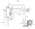
- FIG. 2 shows a schematic diagram of a liquid holding unit of the reagent dispensing mechanism 17 according to the present invention, a driving unit that changes the position of the liquid holding unit, and a mechanism that changes the holding position of the liquid 56.
- the liquid holding unit includes a nozzle 41 that sucks and discharges a reagent for blood coagulation reaction, a heat block 43 that heats the liquid 56, a nozzle connection unit 42 that connects the nozzle 41 and the heat block 43, and a liquid holding unit and the liquid 56.
- the channel 45 is connected to a mechanism for changing the holding position of the gas, and the channel connection unit 44 is connected to the channel 45 and the heat block 43.
- a motor 46 is fixed to the upper and lower bases 50, pulleys 47 are fixed to the motor 46 and the upper and lower bases 50, and the pulleys 47 are connected by a belt 48. 49, the belt 48 and the reagent dispensing mechanism 17 are fixed.
- a motor 46 is fixed to the left and right bases 51, pulleys 47 are fixed to the motor 46 and the left and right bases 51, the pulleys 47 are connected by belts 48, and the belt 48 and the upper and lower bases 50 of the left and right bases 51 are fixed.
- the driving method and the fixing method shown here are merely examples and do not limit the present invention.
- the liquid holding part is disposed between the nozzle 41 and a syringe part (drive mechanism) described later.
- the flow path connects the liquid holding part and the syringe part (drive mechanism).
- the heat block 43 is heated by a heater, and the liquid 56 is heated through the heat block. This does not limit the heating method of the liquid 56, and a heating method similar to a heater may be used. For example, heating of the liquid 56 by a heating wire or a Peltier element can be considered. Strictly speaking, a heater typified by a thermocouple or a Peltier element is separate from the heat block 43, but in this specification, the heat block 43 including the heater is referred to as a heater.
- the mechanism for changing the holding position of the liquid 56 includes an outer cylinder 52 and a plunger 53 as a syringe part, a rack 54 that moves the plunger 53 up and down, a motor 46, and a gear 55 that transmits the movement of the motor 46 to the rack 54. Is done.
- the reagent is aspirated and discharged by changing the pressure in the nozzle 41 by the syringe unit (drive mechanism).
- the syringe unit (drive mechanism) is controlled by the reagent dispensing control unit 34 (control unit). Accordingly, the reagent dispensing control unit 34 controls the suction and discharge of the reagent from the nozzle 41.
- the rotational movement of the motor 46 fixed to the vertical base 50 is converted into the vertical movement through the pulley 47 and the belt 48.
- the left / right operation of the reagent dispensing mechanism 17 converts the rotation operation of the motor 46 fixed to the left / right base 51 into a left / right operation via a pulley 47 and a belt 48.
- the operation of the syringe unit converts the rotational motion of the motor 46 to the rack 54 via the gear 55 and converts it into a vertical motion.
- the liquid 56 at this time includes not only a reagent but also a diluent and a sample. That is, the nozzle 41 can also perform suction and discharge of a sample depending on the analysis item, and the nozzle 41 can be used in common for the reagent and the sample.
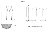
- FIG. 3 shows an appropriate nozzle 41 that stirs the sample and the reagent at a moment when the reagent is discharged in the dispensing of the reagent where the reagent dispensing position is constant and bubbles are not mixed in the mixed solution of the sample and the reagent. And the conditions under which the nozzle 41 can be stopped at the same position each time by pressing the nozzle 41 against the inner wall of the disposable reaction vessel 13 within the range of elasticity of the nozzle 41 will be described.
- the position of the appropriate nozzle 41 when dispensing the reagent will be described.
- the position of the nozzle 41 is a, b, and c in order from the center position between the center position and the inner wall of the disposable reaction vessel 13.
- the nozzle 41 can be stopped at the same position every time by pressing the nozzle 41 against the side surface of the inner wall of the disposable reaction vessel 13. Since the nozzle 41 has an elongated shape in the vertical direction, it can be elastically changed in the horizontal direction, and by pressing the nozzle 41, it is possible to absorb variations in the stopping accuracy of the nozzle 41. is there.
- the coagulation time detection unit includes a plurality of detection units on which a plurality of reaction vessels can be mounted simultaneously, and individual dimensional errors occur in the detection unit.
- An error in the position of the nozzle 41 with respect to the disposable reaction vessel 13 caused by a dimensional error of each detection unit is defined as d.
- e be the position error due to the stopping accuracy of the reagent dispensing mechanism 17.
- the horizontal elastic change range of the nozzle 41 is f
- a relationship of d + e ⁇ f is established as a condition that enables the nozzle 41 to stop at the same position every time.
- the range of elastic change in the horizontal direction means that the tip of the nozzle and the nozzle root can be returned to the original shape without being deformed when the nozzle tip is bent in the horizontal direction and returned to its original position. This is the amount of horizontal displacement.
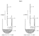
- FIG. 4 explains the operation method of the nozzle 41 to the position where the reagent is discharged and the operation method after dispensing the reagent.
- the operation method of the nozzle 41 to the position for discharging the reagent when the nozzle 41 comes to the center position of the disposable reaction vessel 13, the lowering operation is performed to the height at which the reagent is discharged.
- a parallel operation is performed until it is pressed against the side surface of the inner wall of the disposable reaction vessel 13, and the reagent is discharged while being pressed against the side surface.
- stirring with the sample dispensed in advance is performed. Therefore, it is not necessary to stir using a stirring mechanism.
- the tip of the nozzle 41 is prevented from coming into contact with the disposable reaction vessel 13 by performing the lowering operation first at the center position of the disposable reaction vessel 13. Note that the amount of parallel movement at this time is such that at least an error d + e is added to the radius of the disposable reaction vessel 13, so that even if there is a dimensional error of each detection unit or an error in the position of the nozzle 41, the disposable reaction vessel The nozzle 41 can be brought into contact with the side surfaces of the 13 inner walls. D + e is equal to or less than f as described above.
- the nozzle drive mechanism always discharges a reagent at the same reagent discharge position by driving a certain amount within the range of the elastic change of the nozzle in the horizontal direction and ignoring the above error toward the side surface of the inner wall. can do.
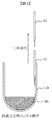
- FIG. 5 shows a method for preventing the liquid temperature from being lowered when the liquid is dispensed into the disposable reaction vessel 13. Since the nozzle 41 is separated from the heat block 43, it is difficult to sufficiently heat the nozzle 41. Therefore, it is expected that the liquid temperature decreases when the liquid passes through the nozzle 41. When the liquid temperature is lowered, it is difficult to reproduce the reaction performed in the body, and a desired measurement result may not be obtained. Therefore, in order to sufficiently warm the nozzle 41, it is conceivable to cover the entire surface with a heat insulating material or to shorten the nozzle 41 as close as possible to the heat block 43.
- the nozzle 41 is brought into contact with the disposable reaction vessel 13 whose temperature is adjusted in the reaction vessel temperature control block 11.
- the reaction vessel temperature control block 11 As a solution to this problem, it is conceivable that the nozzle 41 is brought into contact with the disposable reaction vessel 13 whose temperature is adjusted in the reaction vessel temperature control block 11.
- the coagulation time detection unit is provided with the reaction vessel temperature control block 11 as a temperature-controllable heating source, and the liquid temperature can be prevented from lowering by being pressed against the side surface of the inner wall of the disposable reaction vessel.
- FIG. 6 shows a dispensing method for preventing liquid from entering a slight gap between the nozzle 41 and the disposable reaction vessel 13 when dispensing the liquid.
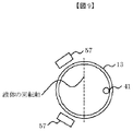
- FIG. 8 is a top view of FIG. 7 and shows an optimal nozzle pressing direction when a plurality of detectors 57 are used.
- the coagulation time detection unit includes a light source that emits light from the bottom surface of the disposable reaction vessel 13 and two opposing detectors that are disposed on the side surface of the disposable reaction vessel 13. The two detectors detect light scattered by the sample, and the coagulation time is calculated from the detection result.
- the nozzle driving mechanism drives the nozzle vertically to the straight line connecting the two detectors after lowering the nozzle to a predetermined depth of the reaction vessel, and discharges the reagent by pressing the nozzle against the reaction vessel.
- the vertical direction here does not mean strict vertical, but may be substantially vertical including a certain amount of error.
- the detector 57 may be symmetrical with respect to the rotation axis of the liquid, the arrangement shown in FIGS. 9 and 10 is also possible.
- a case where two detectors are used is taken as an example.
- the preferred arrangement of detectors 57 is the opposite arrangement shown in FIG. In the blood coagulation test, as described above, since the reaction process is measured from start to finish, one detection occupies the blood coagulation detector 12 until the end of the reaction.
- the detectors 57 are arranged facing each other, the structure of the detection unit can be simplified and manufactured at a lower cost than other arrangements. Moreover, when cost reduction is considered, the case where the detector 57 is made into one is considered. In this case, the detector 57 may be arranged anywhere, but when there are a plurality of detection units, it is desirable that the detectors 57 be in the same direction in order to see the correlation between the detection units.
- the sample can be discharged by the nozzle 41, when the sample is discharged to the disposable reaction vessel 13, it may be discharged while being pressed against the side surface of the inner wall of the reaction vessel in the same manner as the reagent.
- the sample may be dispensed by bringing a nozzle into contact with the bottom surface of the inner wall of the disposable reaction vessel 13.
- the reagent is not limited to the method of dispensing these samples, and the reagent is discharged from above the liquid level of the dispensed sample.
- the nozzle that is elastic in the direction perpendicular to the axial direction in which the reagent is dispensed is pressed against the side surface of the inner wall of the reaction vessel within the elasticity of the nozzle.
- the position for dispensing can be kept constant.
- the reagent dispensing nozzle against the inner wall of the reaction vessel, the reagent falls along the side surface of the inner wall of the reaction vessel, and the reagent is dispensed without air bubbles being mixed into the mixture of the sample and reagent. It becomes possible to note. By not introducing air bubbles, it is possible to prevent disturbance that hinders accurate optical measurement, and to prevent measurement accuracy of blood coagulation ability from being lowered.
Landscapes
- Health & Medical Sciences (AREA)
- Life Sciences & Earth Sciences (AREA)
- Engineering & Computer Science (AREA)
- Chemical & Material Sciences (AREA)
- Immunology (AREA)
- Physics & Mathematics (AREA)
- Hematology (AREA)
- Biomedical Technology (AREA)
- General Health & Medical Sciences (AREA)
- Analytical Chemistry (AREA)
- Pathology (AREA)
- General Physics & Mathematics (AREA)
- Biochemistry (AREA)
- Molecular Biology (AREA)
- Urology & Nephrology (AREA)
- Food Science & Technology (AREA)
- Medicinal Chemistry (AREA)
- Biotechnology (AREA)
- Cell Biology (AREA)
- Microbiology (AREA)
- Biophysics (AREA)
- Ecology (AREA)
- Automatic Analysis And Handling Materials Therefor (AREA)
- Investigating Or Analysing Biological Materials (AREA)
Abstract
Description
11 反応容器温調ブロック
12 凝固時間検出部
13 ディスポーサブル反応容器
14 反応容器供給部
15 凝固時間検体分注ポジション
16 反応容器移送機構
17 試薬昇温機能付き試薬分注機構
18 反応容器廃棄部
19 反応容器移送機構制御部
20 検体分注機構
21 検体ディスク
22 検体容器
23 試薬ディスク
24 試薬容器
31 コンピュータ
32 インターフェース
33 検体分注制御部
34 試薬分注制御部
35 A/D変換機
36 プリンタ
37 メモリ
38 外部出力メディア
39 キーボード
40 CRTディスプレイ(表示装置)
41 ノズル
42 ノズル接続部
43 ヒートブロック
44 流路接続部
45 流路
46 モータ
47 プーリ
48 ベルト
49 駆動機構接続部
50 上下ベース
51 左右ベース
52 外筒
53 プランジャー
54 ラック
55 ギア
56 液体
57 検出器
Claims (11)
- 血液凝固反応用の試薬の吸引及び吐出を行うノズルと、
前記ノズルの該試薬の吸引及び吐出を制御する制御部と、
前記ノズルの位置を変化させるノズル駆動機構と、
試料と該試薬とを混合する反応容器を載置し、該試料の凝固時間を検出する凝固時間検出部と、を備えた自動分析装置において、
前記ノズル駆動機構は、該試料が分注されている該反応容器に対し、前記ノズルを該反応容器の内壁の側面に押し付け、
前記制御部は、該内壁の側面に押し付けた状態で該試薬を該反応容器に吐出することを特徴とする自動分析装置。 - 請求項1記載の自動分析装置において、
前記試薬と前記試料とは、他の撹拌機構を用いることなく、前記試薬が吐出された勢いで撹拌されることを特徴とする自動分析装置。 - 請求項1記載の自動分析装置において、
前記凝固時間検出部は温度調節可能な加熱源を備えた検出部であることを特徴とする自動分析装置。 - 請求項1記載の自動分析装置において、
前記制御部は、前記内壁の側面に押し付けた状態で前記ノズルを上昇させながら前記試薬の吐出を行うことを特徴とする自動分析装置。 - 請求項3記載の自動分析装置において、
前記制御部は、前記内壁の側面に押し付けた状態で前記ノズルを上昇させながら前記試薬の吐出を行うことを特徴とする自動分析装置。 - 請求項1記載の自動分析装置において、
前記制御部は、前記ノズルを用いて前記試料の吸引及び吐出を行うことを特徴とする自動分析装置。 - 請求項6記載の自動分析装置において、
前記制御部は、前記ノズルを前記反応容器の該内壁の側面に押し付けた状態で該試料を吐出し、吐出された該試料の液面より上方かつ該内壁の側面に押し付けた状態で該試薬を該反応容器に吐出することを特徴とする自動分析装置。 - 請求項6記載の自動分析装置において、
前記制御部は、前記ノズルを前記反応容器の内壁の底面に接触させて該試料の分注を行い、分注された該試料の液面より上方かつ該内壁の側面に押し付けた状態で該試薬を該反応容器に吐出することを特徴とする自動分析装置。 - 請求項1記載の自動分析装置において、
前記凝固時間検出部は、前記反応容器の底面から光を照射する光源と、前記反応容器の側面に配置された対向する2つの検出器とを備え、
前記ノズル駆動機構は、前記ノズルを前記反応容器の所定深さまで下降させた後に、前記2つの検出器を結ぶ直線に対し、垂直方向に駆動させ、前記ノズルを該反応容器の内壁の側面に押し付けることを特徴とする自動分析装置。 - 請求項1記載の自動分析装置において、
前記凝固時間検出部は、複数の反応容器を同時に搭載できる複数の検出部から成り、
前記ノズル駆動機構は、夫々の検出部に搭載された反応容器に対し、前記ノズルを所定深さまで下降させた後に、前記ノズルの水平方向の弾性変化の範囲内、かつ、該内壁の側面に向かって一定量駆動させることで、前記ノズルを該反応容器の内壁の側面に押し付けることを特徴とする自動分析装置。 - 請求項1記載の自動分析装置において、
前記凝固時間検出部は、前記反応容器の底面から光を照射する光源と、前記反応容器の側面に配置された1つの検出器とを備え、
前記ノズル駆動機構は、前記ノズルを前記反応容器の所定深さまで下降させた後に、前記2つの検出器を結ぶ直線に対し、垂直方向に駆動させ、前記ノズルを該反応容器の内壁の側面に押し付けることを特徴とする自動分析装置。
Priority Applications (4)
| Application Number | Priority Date | Filing Date | Title |
|---|---|---|---|
| EP14865780.2A EP3076183B1 (en) | 2013-11-26 | 2014-10-22 | Automatic analyzer |
| JP2015550607A JP6581905B2 (ja) | 2013-11-26 | 2014-10-22 | 自動分析装置 |
| US15/025,586 US9970948B2 (en) | 2013-11-26 | 2014-10-22 | Automatic analyzer |
| CN201480062401.8A CN106133527B (zh) | 2013-11-26 | 2014-10-22 | 自动分析装置 |
Applications Claiming Priority (2)
| Application Number | Priority Date | Filing Date | Title |
|---|---|---|---|
| JP2013-243452 | 2013-11-26 | ||
| JP2013243452 | 2013-11-26 |
Publications (1)
| Publication Number | Publication Date |
|---|---|
| WO2015079829A1 true WO2015079829A1 (ja) | 2015-06-04 |
Family
ID=53198779
Family Applications (1)
| Application Number | Title | Priority Date | Filing Date |
|---|---|---|---|
| PCT/JP2014/078008 Ceased WO2015079829A1 (ja) | 2013-11-26 | 2014-10-22 | 自動分析装置 |
Country Status (5)
| Country | Link |
|---|---|
| US (1) | US9970948B2 (ja) |
| EP (1) | EP3076183B1 (ja) |
| JP (1) | JP6581905B2 (ja) |
| CN (2) | CN110031643A (ja) |
| WO (1) | WO2015079829A1 (ja) |
Cited By (5)
| Publication number | Priority date | Publication date | Assignee | Title |
|---|---|---|---|---|
| EP3173794A1 (de) | 2015-11-25 | 2017-05-31 | Siemens Healthcare Diagnostics Products GmbH | Verfahren zum transfer eines flüssigkeitsvolumens in einem analysegerät |
| JP2018087786A (ja) * | 2016-11-30 | 2018-06-07 | シスメックス株式会社 | 粒子分散装置及び粒子分散方法 |
| WO2018163917A1 (ja) | 2017-03-08 | 2018-09-13 | 株式会社日立ハイテクノロジーズ | 自動分析装置及び自動分析方法 |
| JP2019138765A (ja) * | 2018-02-09 | 2019-08-22 | キヤノンメディカルシステムズ株式会社 | 自動分析装置 |
| JPWO2018150943A1 (ja) * | 2017-02-15 | 2019-12-12 | コニカミノルタ株式会社 | 送液システム、検査システム及び送液方法 |
Families Citing this family (11)
| Publication number | Priority date | Publication date | Assignee | Title |
|---|---|---|---|---|
| JP7011904B2 (ja) * | 2017-07-31 | 2022-01-27 | 株式会社日立ハイテク | 装置、試料における気泡の状態の判別方法、及び分析システム |
| JP6814171B2 (ja) * | 2018-03-19 | 2021-01-13 | 株式会社日立ハイテク | 自動分析装置 |
| JP7002640B2 (ja) * | 2018-04-12 | 2022-01-20 | 株式会社日立ハイテク | 電解質分析装置 |
| NL2021685B1 (en) * | 2018-09-24 | 2020-05-07 | Lely Patent Nv | Milking system with detection system |
| CN112585477B (zh) * | 2018-09-26 | 2024-02-23 | 株式会社日立高新技术 | 自动分析系统 |
| CN109975073B (zh) * | 2019-03-29 | 2024-03-19 | 赫安仕科技(苏州)有限公司 | 一种取液装置及取液方法 |
| CN110780085B (zh) * | 2019-11-04 | 2021-03-09 | 苏州长光华医生物医学工程有限公司 | 一种全自动化学发光免疫分析仪的加样方法 |
| CN111122896A (zh) * | 2019-12-24 | 2020-05-08 | 苏州长光华医生物医学工程有限公司 | 一种医疗仪器的试剂针取液过程控制方法及系统 |
| CN113740494B (zh) * | 2021-09-06 | 2024-02-02 | 贵港台泥东园环保科技有限公司 | 一种危险废物生料磨处置用模拟装置 |
| CN113908900A (zh) * | 2021-09-22 | 2022-01-11 | 西安洛科电子科技股份有限公司 | 一种便于安装的无缆式智能分注仪及其安装方法 |
| JP7797173B2 (ja) * | 2021-11-11 | 2026-01-13 | キヤノンメディカルシステムズ株式会社 | 自動分析装置 |
Citations (7)
| Publication number | Priority date | Publication date | Assignee | Title |
|---|---|---|---|---|
| JPH07239334A (ja) * | 1994-02-25 | 1995-09-12 | Fuji Photo Film Co Ltd | 液体の混合方法 |
| JP2003035715A (ja) | 2001-07-19 | 2003-02-07 | Hitachi Ltd | 超音波攪拌装置及びそれを用いた自動分析装置 |
| JP2003057249A (ja) | 2001-08-21 | 2003-02-26 | Hitachi Ltd | 攪拌装置およびそれを用いた自動分析装置 |
| JP2005257491A (ja) * | 2004-03-12 | 2005-09-22 | Hitachi High-Technologies Corp | 自動分析装置 |
| JP2008046031A (ja) * | 2006-08-18 | 2008-02-28 | Sysmex Corp | 血液凝固分析装置 |
| JP2008070355A (ja) | 2006-08-18 | 2008-03-27 | Sysmex Corp | 分注装置、試薬分注装置および検体分析装置 |
| JP2010271203A (ja) * | 2009-05-22 | 2010-12-02 | Hitachi High-Technologies Corp | 液体のサンプリング方法、及び自動分析装置 |
Family Cites Families (12)
| Publication number | Priority date | Publication date | Assignee | Title |
|---|---|---|---|---|
| JPS5312223Y2 (ja) * | 1974-10-02 | 1978-04-03 | ||
| JPS5469497A (en) | 1977-11-12 | 1979-06-04 | Kyoto Daiichi Kagaku Kk | Method and device for measuring blood solidification time |
| JPS5928642A (ja) * | 1982-08-11 | 1984-02-15 | Hitachi Ltd | 散乱光度計 |
| JP2795564B2 (ja) * | 1991-10-08 | 1998-09-10 | アロカ 株式会社 | 高粘性液体の希釈方法 |
| JPH07260797A (ja) * | 1994-03-16 | 1995-10-13 | Sanyo Electric Co Ltd | 分注装置 |
| JPH08327507A (ja) * | 1995-05-30 | 1996-12-13 | Sanyo Electric Co Ltd | 分注方法 |
| JP2009075082A (ja) * | 2007-08-31 | 2009-04-09 | Olympus Corp | 分注装置、分注方法及び自動分析装置 |
| EP2293083B1 (en) * | 2008-06-17 | 2018-09-05 | Hitachi High-Technologies Corporation | Automatic analyzer |
| JP2010117222A (ja) * | 2008-11-12 | 2010-05-27 | Beckman Coulter Inc | 試料容器、分注装置、分注方法及び分析装置 |
| JP5379044B2 (ja) * | 2010-02-25 | 2013-12-25 | 株式会社日立ハイテクノロジーズ | 自動分析装置 |
| JP5674440B2 (ja) * | 2010-12-01 | 2015-02-25 | 株式会社日立ハイテクノロジーズ | 自動分析装置 |
| JP5752545B2 (ja) | 2011-09-22 | 2015-07-22 | 株式会社日立ハイテクノロジーズ | 自動分析装置 |
-
2014
- 2014-10-22 US US15/025,586 patent/US9970948B2/en active Active
- 2014-10-22 CN CN201910308490.4A patent/CN110031643A/zh active Pending
- 2014-10-22 JP JP2015550607A patent/JP6581905B2/ja active Active
- 2014-10-22 WO PCT/JP2014/078008 patent/WO2015079829A1/ja not_active Ceased
- 2014-10-22 EP EP14865780.2A patent/EP3076183B1/en active Active
- 2014-10-22 CN CN201480062401.8A patent/CN106133527B/zh active Active
Patent Citations (7)
| Publication number | Priority date | Publication date | Assignee | Title |
|---|---|---|---|---|
| JPH07239334A (ja) * | 1994-02-25 | 1995-09-12 | Fuji Photo Film Co Ltd | 液体の混合方法 |
| JP2003035715A (ja) | 2001-07-19 | 2003-02-07 | Hitachi Ltd | 超音波攪拌装置及びそれを用いた自動分析装置 |
| JP2003057249A (ja) | 2001-08-21 | 2003-02-26 | Hitachi Ltd | 攪拌装置およびそれを用いた自動分析装置 |
| JP2005257491A (ja) * | 2004-03-12 | 2005-09-22 | Hitachi High-Technologies Corp | 自動分析装置 |
| JP2008046031A (ja) * | 2006-08-18 | 2008-02-28 | Sysmex Corp | 血液凝固分析装置 |
| JP2008070355A (ja) | 2006-08-18 | 2008-03-27 | Sysmex Corp | 分注装置、試薬分注装置および検体分析装置 |
| JP2010271203A (ja) * | 2009-05-22 | 2010-12-02 | Hitachi High-Technologies Corp | 液体のサンプリング方法、及び自動分析装置 |
Cited By (11)
| Publication number | Priority date | Publication date | Assignee | Title |
|---|---|---|---|---|
| EP3173794A1 (de) | 2015-11-25 | 2017-05-31 | Siemens Healthcare Diagnostics Products GmbH | Verfahren zum transfer eines flüssigkeitsvolumens in einem analysegerät |
| CN106908617A (zh) * | 2015-11-25 | 2017-06-30 | 西门子医学诊断产品有限责任公司 | 在分析仪中转移液体体积的方法 |
| US10365291B2 (en) | 2015-11-25 | 2019-07-30 | Siemens Healthcare Diagnostics Products Gmbh | Method for transferring a liquid volume in an analyzer |
| CN106908617B (zh) * | 2015-11-25 | 2021-07-09 | 西门子医学诊断产品有限责任公司 | 在分析仪中转移液体体积的方法 |
| JP2018087786A (ja) * | 2016-11-30 | 2018-06-07 | シスメックス株式会社 | 粒子分散装置及び粒子分散方法 |
| US11169057B2 (en) | 2016-11-30 | 2021-11-09 | Sysmex Corporation | Particle dispersion device and particle dispersion method |
| JPWO2018150943A1 (ja) * | 2017-02-15 | 2019-12-12 | コニカミノルタ株式会社 | 送液システム、検査システム及び送液方法 |
| WO2018163917A1 (ja) | 2017-03-08 | 2018-09-13 | 株式会社日立ハイテクノロジーズ | 自動分析装置及び自動分析方法 |
| US11231432B2 (en) | 2017-03-08 | 2022-01-25 | Hitachi High-Tech Corporation | Automatic analysis device and automatic analysis method |
| JP2019138765A (ja) * | 2018-02-09 | 2019-08-22 | キヤノンメディカルシステムズ株式会社 | 自動分析装置 |
| JP7106286B2 (ja) | 2018-02-09 | 2022-07-26 | キヤノンメディカルシステムズ株式会社 | 自動分析装置 |
Also Published As
| Publication number | Publication date |
|---|---|
| CN106133527B (zh) | 2019-04-16 |
| JP6581905B2 (ja) | 2019-09-25 |
| EP3076183A4 (en) | 2017-08-02 |
| US20160238620A1 (en) | 2016-08-18 |
| CN110031643A (zh) | 2019-07-19 |
| EP3076183B1 (en) | 2021-06-30 |
| US9970948B2 (en) | 2018-05-15 |
| CN106133527A (zh) | 2016-11-16 |
| JPWO2015079829A1 (ja) | 2017-03-16 |
| EP3076183A1 (en) | 2016-10-05 |
Similar Documents
| Publication | Publication Date | Title |
|---|---|---|
| JP6581905B2 (ja) | 自動分析装置 | |
| JP7450656B2 (ja) | 自動分析装置 | |
| CN104854459B (zh) | 自动分析装置 | |
| JP6567873B2 (ja) | 自動分析装置 | |
| JP6462844B2 (ja) | 自動分析装置 | |
| JP5210902B2 (ja) | 自動分析装置及び自動分析装置を用いた分析方法 | |
| JP2014126415A (ja) | 自動分析装置 | |
| CN110023765A (zh) | 自动分析装置 | |
| CN110352355B (zh) | 自动分析装置和分析方法 | |
| JP6151096B2 (ja) | 自動分析装置 | |
| JP6049671B2 (ja) | 自動分析装置及びその分注プローブ |
Legal Events
| Date | Code | Title | Description |
|---|---|---|---|
| 121 | Ep: the epo has been informed by wipo that ep was designated in this application |
Ref document number: 14865780 Country of ref document: EP Kind code of ref document: A1 |
|
| ENP | Entry into the national phase |
Ref document number: 2015550607 Country of ref document: JP Kind code of ref document: A |
|
| REEP | Request for entry into the european phase |
Ref document number: 2014865780 Country of ref document: EP |
|
| WWE | Wipo information: entry into national phase |
Ref document number: 15025586 Country of ref document: US Ref document number: 2014865780 Country of ref document: EP |
|
| NENP | Non-entry into the national phase |
Ref country code: DE |