WO2015075955A1 - マイクロホンスタンドおよびマイクロホンスタンドセット - Google Patents
マイクロホンスタンドおよびマイクロホンスタンドセット Download PDFInfo
- Publication number
- WO2015075955A1 WO2015075955A1 PCT/JP2014/060672 JP2014060672W WO2015075955A1 WO 2015075955 A1 WO2015075955 A1 WO 2015075955A1 JP 2014060672 W JP2014060672 W JP 2014060672W WO 2015075955 A1 WO2015075955 A1 WO 2015075955A1
- Authority
- WO
- WIPO (PCT)
- Prior art keywords
- microphone
- microphone stand
- slit
- stand
- cuts
- Prior art date
- Legal status (The legal status is an assumption and is not a legal conclusion. Google has not performed a legal analysis and makes no representation as to the accuracy of the status listed.)
- Ceased
Links
Images


Classifications
-
- H—ELECTRICITY
- H04—ELECTRIC COMMUNICATION TECHNIQUE
- H04R—LOUDSPEAKERS, MICROPHONES, GRAMOPHONE PICK-UPS OR LIKE ACOUSTIC ELECTROMECHANICAL TRANSDUCERS; DEAF-AID SETS; PUBLIC ADDRESS SYSTEMS
- H04R1/00—Details of transducers, loudspeakers or microphones
- H04R1/08—Mouthpieces; Microphones; Attachments therefor
-
- F—MECHANICAL ENGINEERING; LIGHTING; HEATING; WEAPONS; BLASTING
- F16—ENGINEERING ELEMENTS AND UNITS; GENERAL MEASURES FOR PRODUCING AND MAINTAINING EFFECTIVE FUNCTIONING OF MACHINES OR INSTALLATIONS; THERMAL INSULATION IN GENERAL
- F16M—FRAMES, CASINGS OR BEDS OF ENGINES, MACHINES OR APPARATUS, NOT SPECIFIC TO ENGINES, MACHINES OR APPARATUS PROVIDED FOR ELSEWHERE; STANDS; SUPPORTS
- F16M11/00—Stands or trestles as supports for apparatus or articles placed thereon ; Stands for scientific apparatus such as gravitational force meters
- F16M11/20—Undercarriages with or without wheels
- F16M11/22—Undercarriages with or without wheels with approximately constant height, e.g. with constant length of column or of legs
-
- F—MECHANICAL ENGINEERING; LIGHTING; HEATING; WEAPONS; BLASTING
- F16—ENGINEERING ELEMENTS AND UNITS; GENERAL MEASURES FOR PRODUCING AND MAINTAINING EFFECTIVE FUNCTIONING OF MACHINES OR INSTALLATIONS; THERMAL INSULATION IN GENERAL
- F16M—FRAMES, CASINGS OR BEDS OF ENGINES, MACHINES OR APPARATUS, NOT SPECIFIC TO ENGINES, MACHINES OR APPARATUS PROVIDED FOR ELSEWHERE; STANDS; SUPPORTS
- F16M11/00—Stands or trestles as supports for apparatus or articles placed thereon ; Stands for scientific apparatus such as gravitational force meters
- F16M11/20—Undercarriages with or without wheels
- F16M11/24—Undercarriages with or without wheels changeable in height or length of legs, also for transport only, e.g. by means of tubes screwed into each other
- F16M11/26—Undercarriages with or without wheels changeable in height or length of legs, also for transport only, e.g. by means of tubes screwed into each other by telescoping, with or without folding
- F16M11/28—Undercarriages for supports with one single telescoping pillar
-
- F—MECHANICAL ENGINEERING; LIGHTING; HEATING; WEAPONS; BLASTING
- F16—ENGINEERING ELEMENTS AND UNITS; GENERAL MEASURES FOR PRODUCING AND MAINTAINING EFFECTIVE FUNCTIONING OF MACHINES OR INSTALLATIONS; THERMAL INSULATION IN GENERAL
- F16M—FRAMES, CASINGS OR BEDS OF ENGINES, MACHINES OR APPARATUS, NOT SPECIFIC TO ENGINES, MACHINES OR APPARATUS PROVIDED FOR ELSEWHERE; STANDS; SUPPORTS
- F16M2200/00—Details of stands or supports
- F16M2200/02—Locking means
- F16M2200/025—Locking means for translational movement
- F16M2200/028—Locking means for translational movement by positive interaction, e.g. male-female connections
Definitions
- the present invention relates to a structure of a microphone stand suitable for mounting an acoustic characteristic measurement microphone arranged at a listening position in a setup of a multi-channel audio system or the like.
- an acoustic characteristic measurement microphone is placed at the listening position, and the test signal output from each speaker is collected by the acoustic characteristic measurement microphone.
- the listening environment at the listening position may be optimized.
- a sound field characteristic adjusting device described in Patent Document 1 as an acoustic device that automatically performs such optimization.
- This sound field characteristic adjusting device outputs impulse signals sequentially from a plurality of speakers, measures the time (sound arrival time) until each impulse signal from each speaker reaches the acoustic characteristic measurement microphone, and In addition, a delay time corresponding to the sound arrival time is set in the delay unit (sound image localization setting).
- pink noise having a flat frequency characteristic is output from each speaker after being delayed by the delay time set for each speaker, and thereby a microphone for measuring acoustic characteristics.
- Frequency analysis of the signal detected in step 1 and set the correction coefficient of each frequency band in the parametric equalizer (setting of the sound field frequency).
- the audio signal of each channel is frequency-corrected so that the frequency characteristics are flat, and then output from each speaker with a delay corresponding to the delay time.
- Non-Patent Document 1 the height of the microphone stand described in Non-Patent Document 1 that is assembled by inserting another cardboard board into the cardboard board is fixed. For this reason, for example, when the height of the user is high, the user places the microphone stand for placing the microphone stand on a table, magazine, etc., so that the position of the microphone for measuring acoustic characteristics is positioned around the height of the user's ear. It needs to be adjusted.
- the present invention has been made in view of the above circumstances, and an object of the present invention is to provide a microphone stand whose height can be adjusted with a simple operation at a lower cost.
- one embodiment of the present invention is a microphone stand that holds a microphone
- the first and second cylindrical parts are inserted into one inside so that the other is slidable in the axial direction and connected in the height direction of the microphone stand,
- a plurality of first cuts are formed side by side in the height direction of the microphone stand, the first notch projecting outward from the straight line connecting the both ends of the center part,
- the first notch and the second cylindrical part are slid relative to the height of the microphone stand so that the plurality of first cuts pass through the second cylindrical part.
- a second cut is formed that is aligned with any of the plurality of first cuts; Inside the first and second cuts aligned by sliding the microphone stand relative to the height of the microphone stand relative to each other, a cord of the microphone The first and second cylindrical parts are disposed as stoppers for preventing relative sliding of the microphone stand in the height direction.
- Another aspect of the present invention is a microphone stand for holding a microphone
- the first and second cylindrical parts are inserted into one inside so that the other is slidable in the axial direction and connected in the height direction of the microphone stand,
- a plurality of first cuts are formed side by side in the height direction of the microphone stand,
- the first notch and the second cylindrical part are slid relative to the height of the microphone stand so that the plurality of first cuts pass through the second cylindrical part.
- a second cut is formed that is aligned with any of the plurality of first cuts;
- the other edge is pushed into one of the first and second cuts that are aligned by sliding the microphone stand relative to the height of the microphone stand relative to each other.
- the microphone stand of the present invention includes the first and second cylindrical parts that are slidably inserted into one and connected in the height direction of the microphone stand, The height of the microphone stand can be easily adjusted by sliding operation.
- the first cylindrical part has a plurality of first incisions with a central portion protruding outward from a straight line connecting both ends, and spaced apart in the height direction of the microphone stand. Is formed with a cut aligned with any one of the plurality of cuts of the first tubular part. For this reason, even if a special stopper is not separately prepared, the microphone cord is placed inside the two cuts aligned by the slide operation of these two cylindrical parts, or the other is placed inside one cut.
- the height of the microphone stand can be fixed by pushing the edge of the notch. Therefore, a microphone stand that can be adjusted in height with a simple operation can be provided at a lower cost.
- FIG. 1 is a diagram showing the appearance and assembly order of parts 1 to 3, 4A, and 4B included in a microphone stand set according to an embodiment of the present invention.
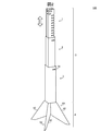
- FIG. 2 is an external view of the microphone stand 100 assembled by the microphone stand set.
- FIGS. 3A to 3D are diagrams showing a procedure for attaching the microphone 7 for measuring acoustic characteristics to the microphone stand 100.
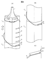
- FIG. 4A to 4C are partial enlarged views of the microphone stand 100 to which the acoustic characteristic measuring microphone 7 is attached.
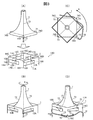
- FIGS. 5A to 5C are diagrams showing other examples of the structure of the lock mechanism.
- the overall configuration of the microphone stand 100 will be described.
- an acoustic characteristic measurement microphone 7 having a quadrangular pyramid-shaped housing as an acoustic characteristic measurement microphone placed at a listening position when setting up a multi-channel audio system including a plurality of speakers is taken as an example.
- FIG. 1 is a view showing the appearance and assembly procedure of parts 1 to 3, 4A, and 4B included in the microphone stand set according to the present embodiment
- FIG. 2 is a microphone stand assembled by the microphone stand set.
- FIG. 3A to 3D are diagrams showing a procedure for attaching the acoustic characteristic measuring microphone 7 to the microphone stand 100
- FIGS. 4A to 4C are acoustic characteristic measuring microphones.
- 7 is a partially enlarged view of the microphone stand 100 with 7 attached thereto.
- FIG. 1 is a view showing the appearance and assembly procedure of parts 1 to 3, 4A, and 4B included in the microphone stand set according to the present embodiment
- FIG. 2 is a microphone stand assembled by the microphone stand set.
- FIG. 3A to 3D are diagrams showing a procedure for attaching the acoustic characteristic measuring microphone 7 to the microphone stand 100
- FIGS. 4A to 4C are acoustic characteristic measuring microphones.
- 7 is a partially enlarged view of the microphone stand 100 with 7
- the microphone stand 100 in a completed state includes a support column 5 that holds the acoustic characteristic measurement microphone 7 at its upper end, and a base unit 6 that holds the support column 5 in a standing posture.
- the microphone stand set includes a plurality of (three in the present embodiment) connecting parts 1 to 3 for forming the support column 5, and two plate-like base parts 4A and 4B constituting the base unit 6. And are included.
- These parts 1 to 3, 4A, and 4B are all formed of a single paperboard (thick paper) having an appropriate strength.
- the three connecting parts 1 to 3 have a rectangular tube shape that can be nested from both directions along the axis.
- Each of these connecting parts 1 to 3 is formed by bending a single paperboard (thick paper) punched into a predetermined pattern so that two sets of opposing side faces are arranged substantially parallel to each other. Only one set of ridge lines of the two opposing ridge lines (folded mountain located at the boundary of adjacent side surfaces) bends. In this way, it can be folded by crushing (so that the angle of one of the two pairs of opposing corners is small and the angle of the other pair is close to 180 degrees).
- the three connecting parts 1 to 3 are sequentially arranged in accordance with the order of the opening size, one end of the connecting part having a large opening size (the end of the two ends positioned on the upper side of the microphone stand 100 in the standing posture). : Hereinafter, the upper end portion) is inserted in the axial direction and connected in the height direction of the microphone stand 100.
- slits notches: height adjustment slits 19, connection slits 22, 29, 32
- the cord 72 of the acoustic characteristic measurement microphone 7 fitted in the slits 19, 22, 29, and 32 constitutes a lock mechanism for locking the connected parts 1 to 3 to each other.
- connection part 1 arranged at the uppermost stage is the uppermost connection part 1
- connection part 3 arranged at the lowermost stage is the lowermost connection part 3, the uppermost connection part 1 and the lowermost stage.
- the connecting part 2 disposed between the connecting part 3 and the connecting part 3 is referred to as an intermediate connecting part 2.
- Microphone holding slits (cuts) 15A to 15D are formed at the upper end of the uppermost connection part 1, one for each of the four side surfaces 14A to 14D, along the width direction of each of the side surfaces 14A to 14D.
- Microphone holding slits (cuts) 15A to 15D are formed at substantially the same height in the microphone stand 100 in the standing posture, and from the positions of the ridgelines 16A to 16D that are different from each other, the center lines 17A to 17A to the centerlines 17A to 15D It extends to a position exceeding 17D.
- the corners 74A to 74D of the housing base 71 of the acoustic characteristic measuring microphone 7 inserted inside the upper end of the uppermost connection part 1 are inserted.
- the cut edges (edges) surrounding the microphone holding slits 15A to 15D are respectively positioned according to the shape of the casing of the acoustic characteristic measurement microphone 7. Incisions 12A to 12D with which the casing of the acoustic characteristic measuring microphone 7 is engaged are provided.
- the housing of the acoustic characteristic measurement microphone 7 since the housing of the acoustic characteristic measurement microphone 7 has a quadrangular pyramid shape, the axis of the corresponding side surface 14A to 14D is formed at the cutout surrounding each microphone holding slit 15A to 15D. Triangular cuts 12A to 12D directed upward are provided at the positions of the direction center lines 17A to 17D, and the ridges 73 of the casing of the acoustic characteristic measurement microphone 7 are engaged with the cuts 12A to 12D. It has become.
- the uppermost connection part 1 is connected to any one of the microphone holding slits 15A to 15D (here, the microphone holding slit 15A) from the upper end surface (the edge surrounding the opening on the upper end side) of the uppermost connection part 1.
- a cord insertion slit (cut) 18 is formed along the ridge line 16A where one end of the microphone holding slit 15A is located.
- the corners of the two side surfaces 14A and 14B on both sides of the cord insertion slit 18 are connected to the uppermost stage so that the cord 72 can be smoothly introduced into the cord insertion slit 18 from the upper end surface side of the uppermost connection part 1.
- the upper end surface of the part 1 is cut obliquely with respect to the ridge line 16 ⁇ / b> A, and the slit width of the cord insertion slit 18 is widened on the upper end surface side of the uppermost connecting part 1.
- a microphone fixing slit (cut) 10 is formed at a position below the microphone holding slits 15A to 15D in the microphone stand 100 in a standing posture.
- the microphone fixing slit 10 intersects with the ridge line 16C of the uppermost connecting part 1 and extends substantially horizontally on the side surfaces 14C and 14D on both sides of the ridge line 16C.
- the cord 72 drawn out from the pedestal corner 74A of the microphone 7 for acoustic characteristic measurement accommodated in the microphone holding slit 15A is inserted into the microphone fixing slit 10 from the corner corresponding to the ridge line 16C of the uppermost connection part 1. Is inserted into both ends of the microphone fixing slit 10 toward the axial center of the connecting part 1 (see FIG. 3D).
- the microphone fixing slit 10 has a slit width slightly narrower than the diameter of the cord 72 of the acoustic measurement microphone 7, and both ends of the microphone fixing slit 10 are formed at the cut ends of the microphone fixing slit 10.
- An incision 13 directed upward is provided at the position.
- the cord 72 pushed to both ends of the microphone fixing slit 10 is firmly held in the notches 13. Thereby, since the cord 72 is gripped by these cuts 13, the cord 72 is prevented from coming out of the microphone fixing slit 10.
- the corner corresponding to the ridge line 16 ⁇ / b> C of the uppermost connecting part 1 is cut off obliquely with respect to the microphone fixing slit 10, and the slit width of the microphone fixing slit 10 is the maximum. It is widened on the ridgeline 16C side of the upper connecting part 1. For this reason, the cord 72 can be smoothly guided from the corner corresponding to the ridge line 16 ⁇ / b> C of the uppermost connection part 1 into the microphone fixing slit 10.
- At least one corner (in this embodiment, the corner corresponding to the ridge line 16B) has an axial center.
- a plurality of height adjusting slits 19 arranged in the direction at predetermined intervals are formed.
- a microphone fixing slit in a state where a connecting slit (described later) 22 of the intermediate connecting part 2 is aligned with any one of the height adjusting slits 19 by a sliding operation of the uppermost connecting part 1 and the intermediate connecting part 2. 10 is inserted into the height adjusting slit 19 exposed from the connecting slit 22 of the intermediate connecting part 2 and pushed into both ends of the height adjusting slit 19 (FIG. 4C). reference).
- each height adjustment slit 19 the corner corresponding to the ridge line 16 ⁇ / b> B of the uppermost connecting part 1 is cut off obliquely with respect to each height adjustment slit 19, and each height adjustment is performed.
- the slit width of the slit 19 for use is widened on the ridge line 16B side of the uppermost connecting part 1. Therefore, the cord 72 can be smoothly guided to the inside of the height adjustment slit 19 from any corner corresponding to the ridge line 16 ⁇ / b> C of the uppermost connection part 1 in any height adjustment slit 19.
- a connecting slit 22 is formed at any one of the corners corresponding to each ridgeline.
- the plurality of height adjusting slits 19 of the uppermost connecting part 1 pass in the axial direction by a sliding operation of the uppermost connecting part 1 inserted inside the upper end of the intermediate connecting part 2. It is formed at a position and is aligned with any height adjusting slit 19 according to the target height of the microphone stand 100.
- the connecting slit 22 has a shape that exposes the entire height adjusting slit 19 aligned therewith.
- connection slit 29 having the same shape as the height adjusting slit 19 is formed.
- the connection slit 29 is arranged so that the connection slit 22 is aligned with the height adjustment slit 19 located closest to the upper end of the uppermost connection part 1. Is formed at a position at a height that does not interfere with the other end.
- a connecting slit 32 is formed at any one of the corners corresponding to each ridgeline.
- the connecting slit 32 is aligned with the connecting slit 29 of the intermediate connecting part 2 by a sliding operation of the lowermost connecting part 3 and the intermediate connecting part 2 inserted therein.
- the connection slit 32 has a shape that exposes the entire connection slit 29 aligned therewith.
- Each of the two base parts 4A, 4B has a bifurcated shape in which two leg portions 42 are branched from the lower end of the rectangular insertion portion 41.
- Such bifurcated base parts 4A and 4B may be formed by punching a pattern according to the outer shape of the base part from the paperboard, or by punching a pattern in which a flap is added to the outer shape of the base part from the paperboard. It may be formed by folding the flap along the outline of the part.
- One base part 4A has a notch having a width corresponding to the thickness of the other base part 4B along the center line from the upper end of the insertion portion 41.
- the other base part 4B has two legs.
- a notch having a width corresponding to the thickness of one base part 4A is formed along the center line from the position between the portions 42.
- the corner 74A from which the cord 72 is drawn is positioned in the cord insertion slit 18. While aligning, the pedestal 71 of the acoustic characteristic measuring microphone 7 is inserted to the position of the microphone holding slits 15A to 15D inside the upper end of the uppermost connection part 1.
- the corners 74A to 74D of the casing base 71 of the microphone 7 for measuring acoustic characteristics are connected to the microphone from one end (end of the ridge line position) of the microphone holding slits 15A to 15D.
- the acoustic characteristic measurement microphone 7 is rotated around the axis in the direction A entering the holding slits 15A to 15D, and the side surface of the housing base 71 of the acoustic characteristic measurement microphone 7 is placed at the other end of the microphone holding slits 15A to 15D. Make contact with the cut end.
- the pedestal corner portions 74A to 74D of the acoustic characteristic measuring microphone 7 are held by the microphone holding slits 15A to 15D.
- the projections (pyramidal shape) of the housing of the acoustic characteristic measuring microphone 7 are formed in the triangular cuts 12A to 12D formed in the cut ends of the microphone holding slits 15A to 15D.
- the ridge line portion of the housing is engaged, thereby preventing the sound measurement microphone 7 from rattling.
- the cord 72 of the acoustic characteristic measurement microphone 7 is wound in the same direction as the direction A in which the acoustic characteristic measurement microphone 7 is rotated from the position of the microphone holding slit 15A. Then, it is pushed into the microphone fixing slit 10 of the uppermost connection part 1. As a result, as shown in FIG. 3D, the cord 72 of the acoustic measurement microphone 7 is fixed in a state of being sandwiched at both ends of the microphone fixing slit 10 of the uppermost connection part 1.
- the cord 72 of the acoustic measurement microphone 7 is wound in the direction A in which the side surface of the housing base 71 of the acoustic characteristic measurement microphone 7 is pressed against the cut end of the other end of the microphone holding slits 15A to 15D, The reverse rotation of the acoustic measurement microphone 7 is blocked, and the acoustic measurement microphone 7 is prevented from falling off the microphone holding slits 15A to 15D.
- the lower end portion of the uppermost connection part 1 is inserted in the axial direction inside the upper end part of the intermediate connection part 2, and the connection slit 22 of the intermediate connection part 2 is inserted into the microphone stand 100.
- the position is adjusted to the height adjustment slit 19 corresponding to the target height, and the height adjustment slit 19 is exposed.
- the cord 72 of the acoustic characteristic measurement microphone 7 drawn out from the microphone fixing slit 10 of the uppermost connection part 1 is connected to the inside of the intermediate connection part 2 from the outside of the intermediate connection part 2 via the connection slit 22. Push into the height adjustment slit 19 of the uppermost connecting part 1.
- FIG. 4A the lower end portion of the uppermost connection part 1 is inserted in the axial direction inside the upper end part of the intermediate connection part 2, and the connection slit 22 of the intermediate connection part 2 is inserted into the microphone stand 100.
- the position is adjusted to the height adjustment slit 19 corresponding to the target height, and the height adjustment slit 19 is exposed.
- the cord 72 fixed to the microphone fixing slit 10 of the uppermost connecting part 1 passes through the connecting slit 22 from the outside of the intermediate connecting part 2 and is connected to the intermediate connecting part. Since it is fixed to the height adjustment slit 19 of the uppermost connection part 1 inside the part 2, the uppermost connection part 1 is prevented from sliding relative to the intermediate connection part 2.
- the lower end portion of the intermediate connection part 2 is inserted in the axial direction inside the upper end portion of the lowermost connection part 3, and the connection slit 29 of the intermediate connection part 2 is inserted into the lowermost stage. It is aligned with the connection slit 32 of the connection part 3 and exposed from the connection slit 32. Then, the cord 72 of the acoustic characteristic measurement microphone 7 drawn out from the connection slit 22 of the intermediate connection part 2 is connected to the inside of the lowermost connection part 3 from the outer side of the lowermost connection part 3 via the connection slit 32. Push into the connecting slit 29 of the intermediate connecting part 2. As a result, as shown in FIG.
- the cord 72 fixed to the connecting slit 22 of the intermediate connecting part 2 passes through the connecting slit 32 from the outside of the lowermost connecting part 3 and is connected to the lowermost connecting part. Since it is fixed to the connection slit 29 of the intermediate connection part 2 inside the part 3, the intermediate connection part 2 is prevented from sliding relative to the lowermost connection part 3.
- the base portion 6 is installed so that the legs 42 of the two crossed base parts 4A and 4B are positioned at substantially equal angular intervals around the axis, and the two base parts 4A are provided.
- the insertion part 41 of 4B is inserted inside the lower end part of the lowermost stage connection part 3.
- FIG. 1 since the insertion part of the two base parts 4A, 4B is arranged at the diagonal position of the lowermost stage connecting part 3 inside the lowermost stage connecting part 3, the crossing angle of the two base parts 4A, 4B Is fixed at almost 90 degrees, and the column portion 5 is firmly supported, and the rectangular tube shape of each of the connecting parts 1 to 3 is maintained, and the column portion 5 maintains an upright state.
- the microphone stand 100 since the other is inserted into one and includes two connecting parts 1 and 2 that can be locked at a desired height, these two The height of the microphone stand 100 can be easily adjusted by sliding the connecting parts 1 and 2.
- a plurality of height adjusting slits 19 are formed at predetermined intervals in the height direction of the microphone stand 100 at the corners of one of the connecting parts 1, Since the connecting slit 22 that is aligned with any one of the height adjusting slits 19 is formed, any one of the height adjusting slits 19 that is aligned by the sliding operation of the two connecting parts 1 and 2 is formed.
- the height of the microphone stand 100 can be fixed by pushing the cord 72 of the acoustic characteristic measuring microphone 7 into the connection slit 22. In this manner, since the cord 72 of the acoustic characteristic measurement microphone 7 can be used as a stopper without using a special stopper separately, the manufacturing cost of the microphone stand 100 can be reduced.
- the microphone stand 100 having a height almost reaching the position of the user's ear is configured by connecting a plurality of parts 1 to 3, 4A, and 4B in the axial direction. Therefore, even if the height of each user is taken into consideration, the paperboard for creating each of the parts 1 to 3, 4A, 4B is, for example, an inexpensive standard (A4 version, etc.) paperboard and a relatively small mold. Can be formed by processing. For this reason, the manufacturing cost of the microphone stand 100 can be further suppressed.
- the cord 72 of the microphone 7 for measuring the acoustic characteristics of the microphone stand 100 is fixed to the microphone stand 100 at a plurality of positions, so that it is held at the upper end of the microphone stand 100.
- the wobbling of the cord 72 hanging from the acoustic characteristic measuring microphone 7 can also be prevented. For this reason, it is not necessary to separately handle the cord 72 of the acoustic characteristic measuring microphone 7, and the attaching operation of the acoustic characteristic measuring microphone 7 can be simplified.
- the three connecting parts 1 to 3 having different opening sizes are positioned in the upper stage as the opening size is smaller.
- the three connecting parts 1 to 3 having different opening sizes are different from each other.
- the connecting parts 1 to 3 may be positioned at the upper level as the opening size is larger.
- only the intermediate connection part 2 is connected to the inside of the two connection parts 1 and 3 by using connection parts having opening sizes different from those of the other two connection parts 1 and 3. You may make it insert the two connection parts 1 and 3 inside the insertion or the upper-lower-end part of the intermediate connection part 2.
- the plurality of height adjusting slits 19 may be formed in the connection parts 2 and 3 other than the uppermost connection part 1.
- the corners of the two side surfaces 14A and 14B on both sides of the cord insertion slit 18 are cut off obliquely so that the cord 72 can be smoothly introduced into the cord insertion slit 18.
- the corner portion located at the connecting portion between the cord insertion slit 18 and the microphone holding slit 15A may be cut off obliquely so that the cord 72 can be smoothly removed from the microphone holding slit 15A.
- the slits 19, 22, 29, and 32 formed in the connecting parts 1 to 3 and the cords of the acoustic characteristic measurement microphone 7 that engage with these slits 19, 22, 29, and 32 are provided.
- 72 constitutes a locking mechanism for locking the connected connecting parts to each other, but this is not necessarily required. For example, while forming an opening at any one corner of the connecting part, cut any one corner of the connecting part into which the connecting part is inserted, and inside the opening of the inner connecting part, You may make it push in the corner
- At least one of the four corners corresponding to each ridge line of the uppermost connecting part 1A includes a plurality at a predetermined interval in the axial direction.
- a height adjusting cut 19A is formed.
- the cut ends of these height adjusting cuts 19A have, for example, a rhombus shape that becomes narrower in the vertical direction.
- the rhombus is mentioned here as an example of the shape of the cut of the height adjustment cut 19A, the shape of the cut of the height adjustment cut 19A is not limited to the rhombus and is folded inside the intermediate connecting part 2A. Any shape that can hold an edge of a later-described slit 22A may be used.
- any one of the four corners corresponding to the ridge lines 26A to 26D is provided at the upper end of the intermediate connection part 2A into which the uppermost connection part 1A is inserted.
- a slit (cut) 22A that cuts one corner up and down is formed.
- the slit 22A is formed at a position where a plurality of height adjusting cuts (cuts) 19A of the uppermost connection part 1A pass in the axial direction by the sliding operation of the intermediate connection part 2A and the uppermost connection part 1A. The position is adjusted to any height adjustment cut 19A according to the target height of the microphone stand 100.
- a fold line 25 is defined from both ends of the slit 22A toward a position on the ridge line 26B below the slit 22A. ing.
- the side faces 24B and 24C of the intermediate connecting part 2A are two folded mountain lines 25. Bend at. Thereby, the edge of the slit 22A protrudes to the inside of the intermediate connection part 2A, and the corner of the intermediate connection part 2A is inserted into the height adjustment cut 19A of the uppermost connection part 1A.
- a plurality of height adjustment cuts 19A are formed in the height direction in the uppermost connection part 1A, and one slit 22A is formed in the upper end portion of the intermediate connection part 2A.
- a plurality of slits 22A are formed in the part 2A in the height direction, and one height adjusting cut 19A is formed at the lower end of the uppermost connecting part 1A, and the height adjusting cut 19A is formed in the uppermost connecting part 1A.
- the connecting parts 1 to 3 having a square cylindrical shape (the opening is substantially square) having the same distance between the two sets of opposing side surfaces are used, but the present invention is not limited to this.
- the connecting parts 1 to 3 may have other foldable rectangular tube shapes (for example, an opening having a substantially rectangular shape) that can be nested from both directions along the axis. Or other cylindrical shapes (for example, cylindrical shape) which cannot be folded may be sufficient.
- each slit 19, 22, 29, 32 may have a shape in which the central portion protrudes outward from a straight line connecting both ends.
- the microphone stand set parts 1 to 3, 4A and 4B are formed of paperboard, but the present invention is not limited to this.
- a flexible resin film or the like may be used.
- 100 microphone stand, 1, 1A, 2, 2A, 3: connection parts, 4A, 4B: base parts, 5: support section, 6: base section, 7: microphone for measuring acoustic characteristics, 10: slit for fixing microphone, 12A to 12D: Notch, 13: Notch, 14A to 14D, 15A to 15D: Microphone holding slit, 16A to 16D: Ridge line of connecting part, 17A to 17D: Center line of side surface of connecting part, 18: Slit for inserting cord, 19: Height adjustment slits 22, 29, 32: Connection slits, 24A to 24D: Side surfaces of connection parts, 25: Folded mountain, 26A to 26D: Side surfaces of connection parts, 41: Insertion part of base parts, 42: Legs of base parts 71: Microphone housing for acoustic characteristics measurement , 72: acoustics measuring microphone code, 73: ridge of acoustics measuring microphone housing, 74A ⁇ 74D: corner portion of the housing base of acous
Landscapes
- Engineering & Computer Science (AREA)
- General Engineering & Computer Science (AREA)
- Mechanical Engineering (AREA)
- Physics & Mathematics (AREA)
- Acoustics & Sound (AREA)
- Signal Processing (AREA)
- Details Of Audible-Bandwidth Transducers (AREA)
Priority Applications (2)
| Application Number | Priority Date | Filing Date | Title |
|---|---|---|---|
| US15/038,071 US9781498B2 (en) | 2013-11-20 | 2014-04-15 | Microphone stand and microphone stand set |
| EP14864829.8A EP3073757B1 (en) | 2013-11-20 | 2014-04-15 | Microphone stand and microphone stand set |
Applications Claiming Priority (2)
| Application Number | Priority Date | Filing Date | Title |
|---|---|---|---|
| JP2013240478A JP6258671B2 (ja) | 2013-11-20 | 2013-11-20 | マイクロホンスタンドおよびマイクロホンスタンドセット |
| JP2013-240478 | 2013-11-20 |
Publications (1)
| Publication Number | Publication Date |
|---|---|
| WO2015075955A1 true WO2015075955A1 (ja) | 2015-05-28 |
Family
ID=53179235
Family Applications (1)
| Application Number | Title | Priority Date | Filing Date |
|---|---|---|---|
| PCT/JP2014/060672 Ceased WO2015075955A1 (ja) | 2013-11-20 | 2014-04-15 | マイクロホンスタンドおよびマイクロホンスタンドセット |
Country Status (4)
| Country | Link |
|---|---|
| US (1) | US9781498B2 (enExample) |
| EP (1) | EP3073757B1 (enExample) |
| JP (1) | JP6258671B2 (enExample) |
| WO (1) | WO2015075955A1 (enExample) |
Families Citing this family (3)
| Publication number | Priority date | Publication date | Assignee | Title |
|---|---|---|---|---|
| NZ714937A (en) * | 2015-12-07 | 2017-02-24 | Meerkat Desk Ltd | A monitor stand |
| FI20175954A1 (fi) * | 2017-10-27 | 2019-04-28 | Teknologian Tutkimuskeskus Vtt Oy | Kotelo melumittaria varten ja melumittari |
| USD1100613S1 (en) * | 2024-04-03 | 2025-11-04 | Orlando Ortega | Shelf spacing tool |
Citations (7)
| Publication number | Priority date | Publication date | Assignee | Title |
|---|---|---|---|---|
| JPS49131931U (enExample) * | 1973-03-09 | 1974-11-13 | ||
| JPS5732868U (enExample) * | 1980-08-04 | 1982-02-20 | ||
| JPS5769366U (enExample) * | 1980-10-16 | 1982-04-26 | ||
| JPH0613292U (ja) | 1992-07-13 | 1994-02-18 | アルパイン株式会社 | 音場特性調整装置 |
| US5490599A (en) * | 1994-12-23 | 1996-02-13 | Tohidi; Fred F. | Long multi-position microphone support stand |
| JP2009278434A (ja) * | 2008-05-15 | 2009-11-26 | Audio Technica Corp | マイクロホンアレイ |
| JP3182513U (ja) * | 2013-01-17 | 2013-04-04 | 劉力行 | 角度と位置が調整可能な音響密閉箱フレーム |
Family Cites Families (8)
| Publication number | Priority date | Publication date | Assignee | Title |
|---|---|---|---|---|
| US3415475A (en) * | 1966-10-13 | 1968-12-10 | Robert R. Goodman | Weighted base |
| US4021012A (en) * | 1976-06-18 | 1977-05-03 | Acroform | Jack stand |
| US4141526A (en) * | 1977-08-09 | 1979-02-27 | Norco Industries, Inc. | Interlocking jack stand |
| US4245808A (en) * | 1979-05-21 | 1981-01-20 | Norco Industries, Inc. | Compact interlocking jack stand |
| JPS6053236B2 (ja) * | 1980-04-30 | 1985-11-25 | 敬之助 松谷 | 巻取り可能な伸縮構造体 |
| US6487298B1 (en) * | 1998-10-30 | 2002-11-26 | Scott A. Hacker | Microphone stand sound monitor |
| FR2805490B1 (fr) * | 2000-02-29 | 2002-06-07 | Christophe Trichet | Dispositif pour appliquer et fixer des revetements en forme de bandes sur une paroi de plafond |
| US6663060B1 (en) * | 2002-09-26 | 2003-12-16 | Robert Wayne Gifford, Sr. | Microphone stand |
-
2013
- 2013-11-20 JP JP2013240478A patent/JP6258671B2/ja active Active
-
2014
- 2014-04-15 WO PCT/JP2014/060672 patent/WO2015075955A1/ja not_active Ceased
- 2014-04-15 US US15/038,071 patent/US9781498B2/en active Active
- 2014-04-15 EP EP14864829.8A patent/EP3073757B1/en active Active
Patent Citations (7)
| Publication number | Priority date | Publication date | Assignee | Title |
|---|---|---|---|---|
| JPS49131931U (enExample) * | 1973-03-09 | 1974-11-13 | ||
| JPS5732868U (enExample) * | 1980-08-04 | 1982-02-20 | ||
| JPS5769366U (enExample) * | 1980-10-16 | 1982-04-26 | ||
| JPH0613292U (ja) | 1992-07-13 | 1994-02-18 | アルパイン株式会社 | 音場特性調整装置 |
| US5490599A (en) * | 1994-12-23 | 1996-02-13 | Tohidi; Fred F. | Long multi-position microphone support stand |
| JP2009278434A (ja) * | 2008-05-15 | 2009-11-26 | Audio Technica Corp | マイクロホンアレイ |
| JP3182513U (ja) * | 2013-01-17 | 2013-04-04 | 劉力行 | 角度と位置が調整可能な音響密閉箱フレーム |
Non-Patent Citations (1)
| Title |
|---|
| "YAMAHA YSP-2200 (YSP-CU2200+NS-SWP600) Quick Reference Guide", 4 November 2013, YAMAHA CORPORATION |
Also Published As
| Publication number | Publication date |
|---|---|
| US20160360306A1 (en) | 2016-12-08 |
| EP3073757B1 (en) | 2018-06-20 |
| EP3073757A4 (en) | 2017-05-17 |
| JP6258671B2 (ja) | 2018-01-10 |
| JP2015103822A (ja) | 2015-06-04 |
| EP3073757A1 (en) | 2016-09-28 |
| US9781498B2 (en) | 2017-10-03 |
Similar Documents
| Publication | Publication Date | Title |
|---|---|---|
| JP7098328B2 (ja) | アレイマイクシステム、及びアレイマイクシステムの組み立て方法 | |
| JP6258671B2 (ja) | マイクロホンスタンドおよびマイクロホンスタンドセット | |
| US8919544B2 (en) | Holder for portable electronic device | |
| US20070086617A1 (en) | Cable coiling method and apparatus | |
| US20120181410A1 (en) | Stand for portable electronic device and folding method thereof | |
| US20160335925A1 (en) | Self-erectable displays and methods of making such self-erectable displays | |
| JP2019523893A (ja) | 建物内に配される音響バッフル | |
| US20100155277A1 (en) | Multimedia Packaging | |
| US20160192102A1 (en) | Surround sound recording array | |
| CA2639933A1 (en) | Universal installation template and method of use for placement of in-wall or in-ceiling speakers | |
| JP2015103822A5 (enExample) | ||
| US11053049B1 (en) | Size adjustable box | |
| JP3193928U (ja) | 折畳式携帯書見台 | |
| JP2017182920A5 (enExample) | ||
| JP3205390U (ja) | 携帯端末用スピーカースタンド及びスピーカースタンド展開紙 | |
| JP6619587B2 (ja) | ドラム用ホルダ | |
| JP6379861B2 (ja) | 音出力端末スタンド、音出力端末スタンドの組み立て板材セット | |
| JP2005348190A5 (enExample) | ||
| JP6489398B2 (ja) | 組立式音声拡張装置 | |
| JP5708629B2 (ja) | マイクロホン装置 | |
| JP2006243585A (ja) | 譜面台装置 | |
| CN202190397U (zh) | 微型扬声器件 | |
| EP2868934A1 (en) | Connecting hole having a teeth-like configuration | |
| JP3195939U (ja) | 表示画面拡大具 | |
| JP3035131U (ja) | スピーカ |
Legal Events
| Date | Code | Title | Description |
|---|---|---|---|
| 121 | Ep: the epo has been informed by wipo that ep was designated in this application |
Ref document number: 14864829 Country of ref document: EP Kind code of ref document: A1 |
|
| REEP | Request for entry into the european phase |
Ref document number: 2014864829 Country of ref document: EP |
|
| WWE | Wipo information: entry into national phase |
Ref document number: 2014864829 Country of ref document: EP |
|
| NENP | Non-entry into the national phase |
Ref country code: DE |
|
| WWE | Wipo information: entry into national phase |
Ref document number: 15038071 Country of ref document: US |