WO2015075869A1 - ワークの切断方法 - Google Patents
ワークの切断方法 Download PDFInfo
- Publication number
- WO2015075869A1 WO2015075869A1 PCT/JP2014/005413 JP2014005413W WO2015075869A1 WO 2015075869 A1 WO2015075869 A1 WO 2015075869A1 JP 2014005413 W JP2014005413 W JP 2014005413W WO 2015075869 A1 WO2015075869 A1 WO 2015075869A1
- Authority
- WO
- WIPO (PCT)
- Prior art keywords
- wire
- workpiece
- cutting
- cut
- wafer
- Prior art date
- Legal status (The legal status is an assumption and is not a legal conclusion. Google has not performed a legal analysis and makes no representation as to the accuracy of the status listed.)
- Ceased
Links
Images



Classifications
-
- B—PERFORMING OPERATIONS; TRANSPORTING
- B28—WORKING CEMENT, CLAY, OR STONE
- B28D—WORKING STONE OR STONE-LIKE MATERIALS
- B28D5/00—Fine working of gems, jewels, crystals, e.g. of semiconductor material; apparatus or devices therefor
- B28D5/04—Fine working of gems, jewels, crystals, e.g. of semiconductor material; apparatus or devices therefor by tools other than rotary type, e.g. reciprocating tools
- B28D5/045—Fine working of gems, jewels, crystals, e.g. of semiconductor material; apparatus or devices therefor by tools other than rotary type, e.g. reciprocating tools by cutting with wires or closed-loop blades
-
- B—PERFORMING OPERATIONS; TRANSPORTING
- B23—MACHINE TOOLS; METAL-WORKING NOT OTHERWISE PROVIDED FOR
- B23D—PLANING; SLOTTING; SHEARING; BROACHING; SAWING; FILING; SCRAPING; LIKE OPERATIONS FOR WORKING METAL BY REMOVING MATERIAL, NOT OTHERWISE PROVIDED FOR
- B23D57/00—Sawing machines or sawing devices not covered by one of the preceding groups B23D45/00 - B23D55/00
- B23D57/0007—Sawing machines or sawing devices not covered by one of the preceding groups B23D45/00 - B23D55/00 using saw wires
-
- B—PERFORMING OPERATIONS; TRANSPORTING
- B23—MACHINE TOOLS; METAL-WORKING NOT OTHERWISE PROVIDED FOR
- B23D—PLANING; SLOTTING; SHEARING; BROACHING; SAWING; FILING; SCRAPING; LIKE OPERATIONS FOR WORKING METAL BY REMOVING MATERIAL, NOT OTHERWISE PROVIDED FOR
- B23D61/00—Tools for sawing machines or sawing devices; Clamping devices for these tools
- B23D61/18—Sawing tools of special type, e.g. wire saw strands, saw blades or saw wire equipped with diamonds or other abrasive particles in selected individual positions
- B23D61/185—Saw wires; Saw cables; Twisted saw strips
-
- B—PERFORMING OPERATIONS; TRANSPORTING
- B24—GRINDING; POLISHING
- B24B—MACHINES, DEVICES, OR PROCESSES FOR GRINDING OR POLISHING; DRESSING OR CONDITIONING OF ABRADING SURFACES; FEEDING OF GRINDING, POLISHING, OR LAPPING AGENTS
- B24B27/00—Other grinding machines or devices
- B24B27/06—Grinders for cutting-off
- B24B27/0633—Grinders for cutting-off using a cutting wire
-
- B—PERFORMING OPERATIONS; TRANSPORTING
- B28—WORKING CEMENT, CLAY, OR STONE
- B28D—WORKING STONE OR STONE-LIKE MATERIALS
- B28D7/00—Accessories specially adapted for use with machines or devices of the preceding groups
- B28D7/02—Accessories specially adapted for use with machines or devices of the preceding groups for removing or laying dust, e.g. by spraying liquids; for cooling work
-
- H—ELECTRICITY
- H10—SEMICONDUCTOR DEVICES; ELECTRIC SOLID-STATE DEVICES NOT OTHERWISE PROVIDED FOR
- H10P—GENERIC PROCESSES OR APPARATUS FOR THE MANUFACTURE OR TREATMENT OF DEVICES COVERED BY CLASS H10
- H10P54/00—Cutting or separating of wafers, substrates or parts of devices
-
- H—ELECTRICITY
- H10—SEMICONDUCTOR DEVICES; ELECTRIC SOLID-STATE DEVICES NOT OTHERWISE PROVIDED FOR
- H10P—GENERIC PROCESSES OR APPARATUS FOR THE MANUFACTURE OR TREATMENT OF DEVICES COVERED BY CLASS H10
- H10P90/00—Preparation of wafers not covered by a single main group of this subclass, e.g. wafer reinforcement
Definitions
- the present invention relates to a workpiece cutting method using a wire saw.
- a wire saw is a device that moves a wire (high-strength steel wire) at a high speed and applies a slurry to the workpiece (for example, a silicon ingot) to cut and simultaneously cut a large number of wafers ( Patent Document 1).
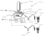
- FIG. 6 shows an outline of an example of a conventional general wire saw.
- the wire saw 101 is mainly cut by a wire 102 for cutting a workpiece, a wire guide 103 around which the wire 102 is wound, a tension applying mechanism 104 for applying tension to the wire 102, and the like.
- a workpiece feeding means 105 for feeding a workpiece, a nozzle 106 for supplying a slurry in which abrasive grains such as SiC fine powder are dispersed and mixed in a coolant at the time of cutting, and the like are configured.
- the wire 102 is fed out from one wire reel bobbin 107, passes through a traverser 108, and passes through a tension applying mechanism 104 including a powder clutch (constant torque motor 109), a dancer roller (dead weight) (not shown) and the like, and then a wire guide 103.
- the wire 102 is wound around the wire guide 103 about 300 to 400 times, and then wound around the wire reel bobbin 107 ′ through the other tension applying mechanism 104 ′.
- the wire guide 103 is a roller in which polyurethane resin is press-fitted around a steel cylinder and grooves are cut at a constant pitch on the surface thereof.
- the wound wire 102 is predetermined by a drive motor 110. It can be driven in a reciprocating direction with a period.
- a nozzle 106 is provided in the vicinity of the wire guide 103 and the wound wire 102, and slurry can be supplied from the nozzle 106 to the wire guide 103 and the wire 102 at the time of cutting. And after cutting, it is discharged as waste slurry.
- the length of the wire 102 that is supplied to cut one workpiece of the wire 102 used in the wire saw is referred to as a new wire supply amount.
- the wire 102 has a length of several hundred km wound around a wire reel bobbin 107, and a plurality of workpieces are cut by the wire 102 wound around the wire reel bobbin 107.
- a wire reel bobbin having a winding length of 510 km is used to cut three workpieces with a new line supply amount used for cutting one workpiece being 170 km.
- the new wire supply amount per cut 85 km, the length of the same wire, that is, the number of workpieces that can be cut with one wire reel bobbin can be increased to six.
- the problem with the above-mentioned method is that the amount of wear of the wire itself when cutting the workpiece is increased by the amount of the new wire supply, and the diameter of the wire is larger than before the new wire supply is reduced. There is a problem that it becomes thin. When the wire diameter is reduced, the quality of the wafer after cutting is deteriorated.
- a typical wafer quality is wafer warpage. It is desirable that the wafer after cutting is flat and has less warpage. However, when the diameter of the wire is reduced, the amount of slurry carried on the wire is reduced and the cutting efficiency is lowered, so that the warpage of the wafer after cutting is increased.
- the present invention has been made in view of the above-described problems.
- the used wire used for cutting the previous workpiece is cut again under the condition different from the previous workpiece cutting condition.
- An object of the present invention is to provide a work cutting method capable of reducing the occurrence of wire breakage and suppressing deterioration of warpage of a wafer while increasing the number of work pieces that can be cut with a wire.
- a wire row is formed by a wire that runs in an axial direction spirally wound between a plurality of wire guides, and a workpiece is pressed against the wire row,
- the wire tension is set to a value in the range of 87 to 95% with respect to the wire tension in the previous workpiece cutting, and the new line supply amount at the time of cutting the next workpiece is the value at the time of cutting the previous workpiece.
- a workpiece cutting method in which the wire is reused and the next workpiece is cut as a value in a range of 125% or more with respect to a new wire supply amount.
- the wire tension and the new wire supply amount with respect to the wire tension and the new wire supply amount at the previous use are controlled so that they are within the above range.
- it is difficult for the wire to break the deterioration of the warpage of the wafer can be suppressed, and the wafer quality can be maintained at the same level as the previous cutting.
- the workpiece feed rate is set to a value in the range of 83 to 91% with respect to the workpiece feed rate in the previous workpiece cutting. In this way, even when the workpiece is cut using the used wire again, it is possible to more reliably suppress the deterioration of the warpage of the wafer after cutting.
- the work cutting method of the present invention by reusing used wires, the number of works that can be cut with the same wire can be greatly increased, and the cost of the wires can be greatly reduced. Furthermore, when the wire is used again, the wire tension and the new wire supply amount are controlled within an appropriate range as in the present invention, and the cutting is performed, so that the occurrence rate of the wire breakage and the quality of the wafer after the cutting can be improved. Deterioration can be suppressed, and a wafer having the same quality as the previous cutting can be obtained.
- the present invention is not limited to this.
- the diameter of the wire is thin, so that the wire is broken or the wafer quality is deteriorated. there were.
- the present inventor has intensively studied to solve such problems.
- the wire tension and new wire supply amount are 87 to 95% of the wire tension and new wire supply amount at the previous cutting of the workpiece, respectively.
- the wire cutting method of the present invention will be described below with reference to FIGS. In the following, a case will be described in which the wire cutting method of the present invention is applied when the wire already used for cutting the workpiece once is used again and the workpiece is cut a second time.
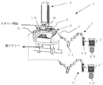
- a wire saw 1 used in the workpiece cutting method of the present invention will be described with reference to FIG.
- the wire saw 1 mainly holds a wire 2 for cutting the workpiece W, a wire guide 3, a wire tension applying mechanism 4, 4 ′ for applying tension to the wire 2, and the workpiece W.
- the workpiece feeding means 5 is pressed down relatively while being pushed, and the nozzle 6 is used to supply the machining fluid to the wire 2 at the time of cutting.
- the wire 2 is fed out from one wire reel bobbin 7 and passes through a traverser 13 and a wire tension applying mechanism 4 including a powder clutch (constant torque motor 14), a dancer roller (dead weight) (not shown), etc. It is in 3.
- the wire 2 is wound around the plurality of wire guides 3 by about 300 to 400 times to form the wire row 16.
- the wire 2 is wound around a wire reel bobbin 7 'through another wire tension applying mechanism 4'.
- As this wire for example, a high tensile steel wire or the like can be used.
- the wire reel bobbins 7 and 7 ' are rotationally driven by wire reel bobbin drive motors 15 and 15'. Further, the wire tension applied to the wire 2 is precisely adjusted by the tension applying mechanisms 4 and 4 ′.
- the nozzle 6 supplies the machining liquid to the contact portion between the workpiece W and the wire 2.
- the nozzle 6 is not particularly limited, but can be disposed above the wire 2 wound around the wire guide 3.
- the nozzle 6 is connected to a slurry tank (not shown), and the supplied slurry can be supplied from the nozzle 6 to the wire 2 by controlling the supply temperature by a slurry chiller (not shown). it can.
- the kind of the working fluid used during the cutting of the workpiece W is not particularly limited, and the same one as the conventional one can be used.
- silicon carbide abrasive grains or diamond abrasive grains are dispersed in the coolant. be able to.
- a water-soluble or oil-based coolant can be used as the coolant.
- the workpiece feeding means 5 includes a workpiece feeding table 9 for feeding workpieces, an LM guide 10, a workpiece clamp 11 for gripping the workpiece, a slicing plate 12, etc., and workpiece feeding along the LM guide 10 under computer control.
- a workpiece feeding table 9 for feeding workpieces
- an LM guide 10 for feeding workpieces
- a workpiece clamp 11 for gripping the workpiece
- a slicing plate 12 etc. workpiece feeding along the LM guide 10 under computer control.
- the wire guide 3 is a roller in which polyurethane resin is press-fitted around a steel cylinder and grooves are cut at a predetermined pitch on the surface of the wire guide 3.
- the wire guide 3 can prevent damage to the wire 2 and suppress wire breakage and the like.
- the wire guide 3 is configured such that the wound wire 2 can reciprocate in the axial direction by a driving motor 8.
- the traveling distance in both directions of the wire 2 is not made the same, but the traveling distance in one direction is made longer. In this way, a new line of the wire 2 is supplied in the direction of a long travel distance by reciprocating the wire 2.
- the drive motor 8 can also adjust the new line supply amount, which is the length of the wire 2 that is supplied to cut one workpiece.
- work W of this invention at the time of using this wire saw 1 is demonstrated.
- a plurality of workpieces W are sequentially pressed against the wire row 16 and cut while reciprocating the wire 2 as described above.
- the wire 2 is stopped.
- the first workpiece is cut (S101 in FIG. 1).
- This first cutting of the workpiece can be performed by a cutting method similar to the conventional one.
- the wire used for cutting is not worn, a wafer having a sufficiently large diameter and a low occurrence rate of breakage of the wire and having good wafer quality after cutting can be obtained.
- the wire 2 wound around the wire reel bobbin 7 'at the time of the first cutting is rewound onto the wire reel bobbin 7, and the wire 2 used once is used as the next workpiece. Prepare to use for cutting W. At this time, the used wire 2 can be reused as it is for the next second work cutting without performing a cleaning process or the like.
- the wire 2 is reciprocated in the axial direction by the drive motor 8 while applying tension to the wire 2 by the wire tension applying mechanisms 4 and 4 ′.
- the wire tension is set to a value in the range of 87 to 95% with respect to the wire tension in the previous work cutting (in this case, the first cutting). Since the diameter of the wire is reduced due to wear compared to the previous cutting of the workpiece, the breaking strength of the wire is reduced. Therefore, when the wire is used again, the wire tension is set to a value of 95% or less with respect to the previous cutting of the workpiece. Further, if the wire tension is not too small and is 87% or more, the quality of the wafer after cutting is unlikely to deteriorate.
- FIG. 4 shows the influence on the wafer quality when the wire tension when the wire 2 is used again is made smaller than the wire tension of the normal setting (the same wire tension as when the previous workpiece was cut).
- the horizontal axis represents wire tension
- the vertical axis represents wafer warpage.
- the wire tension and the warpage of the wafer are expressed as relative values, assuming that the wire tension at the normal setting and the warpage of the wafer after cutting are 100% respectively.
- the warpage of the wafer tends to increase.
- the new wire supply amount which is the length of the wire 2 supplied to cut one workpiece, is cut when the previous workpiece is cut (in this case, at the first cutting).
- the new line supply amount is set to a value in the range of 125% or more.
- New wire supply amount when cutting workpiece W is related to wire wear amount.
- the amount of wire wear is the difference between the diameter of the wire 2 before being used for cutting the workpiece W and the diameter of the wire 2 after being used for cutting the workpiece W.
- the wire 2 is worn and thinned in the process of cutting the workpiece W.
- the wire wear amount is decreased.
- the wire wear amount is increased.
- the wire wear amount becomes the wire wear amount at the previous cutting. However, it can be adjusted to 80% or less.
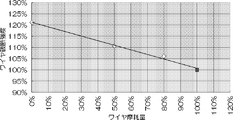
- FIG. 5 shows the influence on the breaking strength.
- FIG. 5 shows the relationship between the breaking strength of the wire and the amount of wire wear.
- the horizontal axis indicates the amount of wire wear
- the vertical axis indicates the breaking strength of the wire.
- the amount of wire wear and the breaking strength of the wire are expressed as relative values with the amount of wire wear and the breaking strength of the normal setting (the same amount of new wire supplied as the previous cutting) being 100%. As shown in FIG.
- the diameter of the split wire can be kept thick, and the breaking strength of the wire is about 5% larger than the breaking strength when the new wire supply amount is the same as the previous cutting. This corresponds to lowering the wire tension by about 10%, and wire breakage is less likely to occur.
- the new wire supply amount is increased as described above, the occurrence of wire breakage can be suppressed even when the used wire 2 is used again, and the wafer quality such as wafer warpage is greatly deteriorated.
- the cutting can be performed without causing it.
- the new line supply amount is excessively increased, the amount of wire consumed for cutting per work increases. Therefore, the new line supply amount is preferably not excessively increased, for example, 200% or less. To do.
- the workpiece W is relatively pushed down by the workpiece feeding means 5, the workpiece W is pressed against the wire row 16, and cutting of the first workpiece W in reuse is started.
- the cutting is advanced while supplying the machining fluid from the nozzle 6 to the contact portion between the workpiece W and the wire 2.
- the work feed speed it is preferable to set the work feed speed to a value in the range of 83 to 91% with respect to the work feed speed in the previous work cutting (in this case, the first cutting).
- the workpiece feed rate it is preferable to set the work feed speed to a value in the range of 83 to 91% with respect to the work feed speed in the previous work cutting (in this case, the first cutting).
- the work W is further pushed down to proceed with cutting, and after cutting is completed, the direction in which the work W is fed out is reversed to cut from the wire row 16.
- the finished workpiece W is pulled out and the cut wafer is collected.
- a plurality of workpieces are sequentially cut into wafers with the wire 2 that has been used once.
- the second cutting using the used wire 2 is performed once (S102 in FIG. 1).
- the number of workpieces that can be cut with the same wires can be greatly increased, and the cost of the wires can be greatly reduced.
- the wire tension and the new wire supply amount are controlled within an appropriate range as in the present invention, and the cutting is performed, so that the occurrence rate of the wire breakage and the quality of the wafer after the cutting can be improved. Deterioration can be suppressed, and a wafer having the same quality as the previous cutting can be obtained.
- the wire tension is set to a value in the range of 87 to 95% with respect to the wire tension in the previous cutting of the workpiece (in this case, the second cutting) at the time of the third cutting.
- the workpiece is repeatedly cut with the new line supply amount set to a value in the range of 125% or more with respect to the new line supply amount when the previous workpiece was cut (in this case, the second cutting). (S103 in FIG. 1).
- the workpiece can be cut using the same wire by using the workpiece cutting method of the present invention for the fourth and fifth and subsequent cuts until the wire diameter decreases and reaches the end of its life. .
- Example 1 A wire saw as shown in FIGS. 2 and 3 was used again to cut the workpiece for the second time using the wire that was already used once for cutting the workpiece.
- the workpiece was a single crystal silicon ingot, and the wire was a high carbon steel brass plated steel wire.
- a single crystal silicon ingot having a diameter of 300 mm and a length of 100 to 450 mm was cut using a wire having a diameter of 0.13 mm, and then the workpiece was cut a second time with a used wire.
- Four silicon ingots were cut per wire reel bobbin when using the first wire, and four silicon ingots were cut using the same wire reel bobbin when the wire was used for the second time.
- the condition at the time of the second use of the wire is 91% of the wire tension with respect to the wire tension, the new wire supply amount and the work feed speed at the first use of the wire.
- the cutting was performed with the new line supply amount set to 125% and the workpiece feed rate unchanged to 100%.
- the rate of occurrence of wire breakage and the warpage of the wafer in Table 1 are relative values with the value at the first use of the wire being 1. The smaller the wire breakage rate and the warp of the wafer, the smaller these relative values. It is desirable that the wire breakage occurrence rate and the warpage of the wafer are smaller.
- the rate of occurrence of wire breakage was 1.6 times that of the first use of the wire, which was at a satisfactory level.
- the warpage of the wafer was 1.07 times the warpage of the wafer at the first use, and was at a level without any problem.
- the workpiece cutting method of the present invention even if the used wire is reused, the occurrence rate of wire breakage and the warpage of the wafer can be reduced to a problem-free level, and the cost of the wire is reduced. As a result, it was confirmed that a wafer with the same quality as the previous cutting could be obtained.
- Example 2 As in Example 1, the wire that was already used once for cutting the workpiece was used again to cut the workpiece for the second time. As shown in Condition 3 in Table 1, the condition when the wire is used for the second time is 91% of the wire tension with respect to the wire tension, the new wire supply amount, and the work feed speed when the wire is used for the first time. Then, cutting was performed with a new line supply amount of 125% and a workpiece feed rate of 90%. As a result, the rate of occurrence of wire breakage was 1.6 times the same as when the wire was used for the first time, and it was at a level without any problem.
- the warpage of the wafer was 0.99 times the warpage of the wafer at the first use, and the wafer quality was improved as compared with Example 1.
- the warpage of the wafer could be further improved by further controlling the workpiece feed rate to 83 to 91%.
- Example 3 Similarly to Example 1, the wire that was already used once for cutting the workpiece was used again to cut the workpiece for the second time. As shown in the condition 4 in Table 1, the condition when the wire is used for the second time is 87% of the wire tension with respect to the wire tension, the new wire supply amount and the work feed speed when the wire is used for the first time. The cutting was performed with the new line supply amount set to 125% and the workpiece feed rate unchanged to 100%. As a result, the occurrence rate of wire breakage was 1.4 times that of the first use of the wire, which was at a satisfactory level. Further, the warpage of the wafer was 1.07 times the warpage of the wafer at the first use, and was at a level without any problem.
- Example 4 As in Example 1, the wire that was already used once for cutting the workpiece was used again to cut the workpiece for the second time. As shown in condition 5 in Table 1, the condition when the wire is used for the second time is 95% of the wire tension with respect to the wire tension, the new wire supply amount and the work feed speed when the wire is used for the first time. The cutting was performed with the new line supply amount set to 125% and the workpiece feed rate unchanged to 100%. As a result, the rate of occurrence of wire breakage was 1.7 times that of the first use of the wire, which was at a satisfactory level. Further, the warpage of the wafer was 1.02 times the warpage of the wafer at the first use, and was at a level without any problem.
- Example 1 As in Example 1, the wire that was already used once for cutting the workpiece was used again to cut the workpiece for the second time. As shown in the condition 1 ′ in Table 1, the condition when the wire is used for the second time is the same wire tension as when the workpiece is cut when the wire is used for the first time (100% with respect to the time when the wire is used for the first time). ), The same new wire supply amount (a value of 100% with respect to the first use of the wire), and the same workpiece feed rate (a value of 100% with respect to the first use of the wire).
- Example 2 As in Example 1, the wire that was already used once for cutting the workpiece was used again to cut the workpiece for the second time. As shown in condition 6 in Table 1, the condition when the wire is used for the second time is 86% of the wire tension with respect to the wire tension, the new wire supply amount and the work feed speed when the wire is used for the first time. The cutting was performed with the new line supply amount set to 125% and the workpiece feed rate unchanged to 100%. As a result, the rate of occurrence of wire breakage was 1.4 times that of the first use of the wire. Further, the warpage of the wafer was 1.2 times that of the first use of the wire. When the wire is used again for cutting the workpiece under the conditions as in Comparative Example 2, a wafer with the same quality as the previous cutting cannot be obtained stably as in Example 1-4, and the wire It was confirmed that it cannot be reused.
- Example 3 As in Example 1, the wire that was already used once for cutting the workpiece was used again to cut the workpiece for the second time. As shown in condition 7 in Table 1, the condition when the wire is used for the second time is that the wire tension is 96% for the wire tension, the new wire supply amount, and the work feed speed when the wire is used for the first time. The cutting was performed with the new line supply amount set to 125% and the workpiece feed rate unchanged to 100%. As a result, the occurrence rate of wire breakage was 3.6 times that of the first use of the wire. Further, the warpage of the wafer was 1.02 times that of the first use of the wire.
- Example 4 As in Example 1, the wire that was already used once for cutting the workpiece was used again to cut the workpiece for the second time. As shown in the condition 8 in Table 1, the condition when the wire is used for the second time is 91% of the wire tension with respect to the wire tension, the new wire supply amount and the work feed speed when the wire is used for the first time. The cutting was performed with the new line supply amount being 124% and the workpiece feed rate being 100% without changing. As a result, the rate of wire breakage was 4.0 times that of the first use of the wire. Further, the warpage of the wafer was 1.07 times that of the first use of the wire. When the wire is used again for cutting the workpiece under the conditions as in Comparative Example 4, a wafer having the same quality as the previous cutting cannot be obtained stably as in Example 1-4, and the wire is substantially It was confirmed that it cannot be reused.
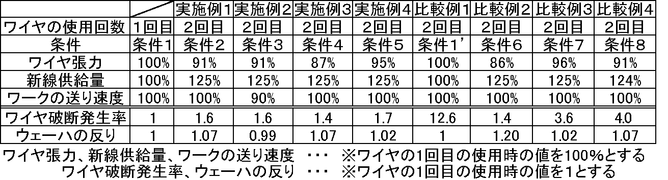
- Table 1 shows a summary of the results of Example 1-4 and Comparative Example 1-4.
- the present invention is not limited to the above embodiment.
- the above-described embodiment is an exemplification, and the present invention has any configuration that has substantially the same configuration as the technical idea described in the claims of the present invention and that exhibits the same effects. Are included in the technical scope.
Landscapes
- Engineering & Computer Science (AREA)
- Mechanical Engineering (AREA)
- Finish Polishing, Edge Sharpening, And Grinding By Specific Grinding Devices (AREA)
- Mechanical Treatment Of Semiconductor (AREA)
- Processing Of Stones Or Stones Resemblance Materials (AREA)
Abstract
Description
ワイヤソーは、ワイヤ(高張力鋼線)を高速走行させて、ここにスラリを掛けながら、ワーク(例えばシリコンインゴットが挙げられる。)を押し当てて切断し、多数のウェーハを同時に切り出す装置である(特許文献1参照)。
図6に示すように、ワイヤソー101は、主に、ワークを切断するためのワイヤ102、ワイヤ102を巻回したワイヤガイド103、ワイヤ102に張力を付与するための張力付与機構104、切断されるワークを送り出すワーク送り手段105、切断時にSiC微粉等の砥粒をクーラントに分散して混合したスラリを供給するためのノズル106等で構成されている。
ただし、この方法でワイヤを再度使用すると、前述した理由により、使用済みのワイヤでは、ワークの切断時にワイヤの破断が起きやすくなる。また、切断後のウェーハの反りが大きくなってしまう。
このようにすれば、使用済みのワイヤを再度使用してワークの切断を行う場合であっても、切断後のウェーハの反りの悪化をより確実に抑制することができる。
上記で説明したように、1度ワークの切断に使用したワイヤを再度使用する場合には、ワイヤの直径が細くなっているため、ワイヤが破断したり、ウェーハ品質が悪化したりするという問題があった。
まず、本発明のワークの切断方法に使用するワイヤソー1について図2を参照しながら説明する。
図2に示すように、ワイヤソー1は、主に、ワークWを切断するためのワイヤ2、ワイヤガイド3、ワイヤ2に張力を付与するためのワイヤ張力付与機構4、4’、ワークWを保持しつつ相対的に押し下げるワーク送り手段5、切断時にワイヤ2に加工液を供給するためのノズル6等で構成されている。
ここで、ワークWの切断中に使用する加工液の種類は特に限定されず、従来と同様のものを用いることができ、例えば炭化珪素砥粒やダイヤモンド砥粒をクーラントに分散させたものとすることができる。クーラントとしては、例えば水溶性又は油性のクーラントを用いることができる。
まず、ワイヤソー1において、ワイヤ2を上記したように往復走行させながら、ワイヤ列16に複数本のワークWを順番に押し当てて切断する。所定の本数のワークを切断し終えたらワイヤ2を停止する。このようにして、1回目のワークの切断を行う(図1のS101)。
この1回目のワークの切断は、従来と同様の切断方法で行うことができる。1回目の切断においては、切断に使用するワイヤは摩耗していないので、直径が十分に太くワイヤの破断の発生率は低く、切断後のウェーハ品質が良好なウェーハを得ることができる。
ワイヤの直径は、前回のワークの切断時に比べ摩耗により細くなっているため、ワイヤの破断強度は低下する。そのため、ワイヤを再度使用する時は、ワイヤ張力を前回のワークの切断時に対して95%以下の値にする。また、ワイヤ張力を小さくし過ぎず、87%以上とすれば、切断後のウェーハの品質が悪化しにくくなる。
図5に示すように、新線供給量を、前回のワークの切断時の新線供給量に対して125%以上の範囲の値にすることで、ワイヤ摩耗量を80%以下にすると、その分ワイヤの直径が太い状態に維持でき、ワイヤの破断強度は前回の切断と同じ新線供給量とした時の破断強度より5%程度大きくなる。これはワイヤ張力を10%程度下げることに相当し、ワイヤ破断が発生しにくくなる。
このように、ワークの送り速度を、前回のワークの切断におけるワークの送り速度に対して91%以下と遅くすることで、ワイヤの直径が細いことが原因のスラリの持ち込み量の減少による切断効率の低下をカバーすることができる。また、ワークの送り速度を、前回のワークの切断におけるワークの送り速度に対して83%以上とすることで、ワークの切断速度が遅くなり過ぎず、ウェーハの生産効率の悪化を抑制することができる。
図2、3に示すようなワイヤソーを用いて、既にワークの切断に1回使用したワイヤを再度使用して、2回目のワークの切断を実施した。
ワークは単結晶シリコンインゴットを、ワイヤは高炭素鋼ブラスメッキ鋼線を用いた。直径300mm、長さ100~450mmの単結晶シリコンインゴットを、直径0.13mmのワイヤを用いて切断を行った後、使用済みのワイヤで2回目のワークの切断を実施した。1回目のワイヤ使用時に、ワイヤリールボビン1本当たりにつきシリコンインゴット4本を切断し、さらに同じワイヤリールボビンにて、ワイヤ2回目の使用時の際に、シリコンインゴット4本を切断した。
表1内の条件2に示すように、ワイヤの2回目の使用時の条件は、1回目のワイヤ使用時のワイヤ張力、新線供給量及びワーク送り速度に対してそれぞれ、ワイヤ張力を91%、新線供給量を125%、ワーク送り速度は変えず100%として切断を行った。表1内のワイヤ破断発生率及びウェーハの反りは、1回目のワイヤ使用時の値を1とした相対値を記載している。ワイヤ破断発生率及びウェーハの反りが小さくなるほど、これらの相対値は小さくなる。ワイヤ破断発生率及びウェーハの反りは値が小さい方が望ましい。
このように、本発明のワークの切断方法であれば、使用済みのワイヤを再度使用してもワイヤ破断の発生率とウェーハの反りを問題のない水準に低減することができ、ワイヤにかかるコストを削減しつつ、前回の切断と同程度の品質のウェーハを得られることが確認できた。
実施例1と同様に、既にワークの切断に1回使用したワイヤを再度使用して、2回目のワークの切断を実施した。
表1内の条件3に示すように、ワイヤの2回目の使用時の条件は、1回目のワイヤ使用時のワイヤ張力、新線供給量及びワーク送り速度に対してそれぞれ、ワイヤ張力を91%、新線供給量を125%、ワーク送り速度を90%として切断を行った。その結果、ワイヤ破断の発生率はワイヤ1回目使用時と同程度の1.6倍となり問題無い水準になった。また、ウェーハの反りについては、1回目使用時のウェーハの反りの0.99倍となり実施例1よりもウェーハ品質が向上した。
このように、本発明のワークの切断方法において、更に、ワーク送り速度を83~91%に制御すれば、ウェーハの反りをより改善できることが確認できた。
実施例1と同様に、既にワークの切断に1回使用したワイヤを再度使用して、2度目のワークの切断を実施した。
表1内の条件4に示すように、ワイヤの2回目の使用時の条件は、1回目のワイヤ使用時のワイヤ張力、新線供給量及びワーク送り速度に対してそれぞれ、ワイヤ張力を87%、新線供給量を125%、ワーク送り速度は変えず100%として切断を行った。
その結果、ワイヤ破断の発生率はワイヤ1回目使用時の1.4倍となり問題無い水準になった。また、ウェーハの反りについては、1回目使用時のウェーハの反りの1.07倍となり問題無い水準になった。
実施例1と同様に、既にワークの切断に1回使用したワイヤを再度使用して、2回目のワークの切断を実施した。
表1内の条件5に示すように、ワイヤの2回目の使用時の条件は、1回目のワイヤ使用時のワイヤ張力、新線供給量及びワーク送り速度に対してそれぞれ、ワイヤ張力を95%、新線供給量を125%、ワーク送り速度は変えず100%として切断を行った。
その結果、ワイヤ破断の発生率はワイヤ1回目使用時の1.7倍となり問題無い水準になった。また、ウェーハの反りについては、1回目使用時のウェーハの反りの1.02倍となり問題無い水準になった。
実施例1と同様に、既にワークの切断に1回使用したワイヤを再度使用して、2回目のワークの切断を実施した。
表1内の条件1’に示すように、ワイヤの2回目の使用時の条件は、ワイヤの1回目使用時でのワークの切断時と同じワイヤ張力(ワイヤの1回目使用時に対して100%の値)、同じ新線供給量(ワイヤの1回目使用時に対して100%の値)、同じワークの送り速度(ワイヤの1回目使用時に対して100%の値)として切断を行った。その結果、ウェーハの反りはワイヤ1回目使用時と同等となったが、ワイヤ破断の発生率が、ワイヤ1回目使用時の12.6倍と大幅に悪化した。
比較例1のような条件でワイヤをワークの切断に再度使用した場合、ワイヤ破断の発生率が高すぎるため安定して高品質のウェーハを得られず、実質上ワイヤの再使用ができないことが確認された。
実施例1と同様に、既にワークの切断に1回使用したワイヤを再度使用して、2回目のワークの切断を実施した。
表1内の条件6に示すように、ワイヤの2回目の使用時の条件は、1回目のワイヤ使用時のワイヤ張力、新線供給量及びワーク送り速度に対してそれぞれ、ワイヤ張力を86%、新線供給量を125%、ワーク送り速度は変えず100%として切断を行った。その結果、ワイヤ破断の発生率が、ワイヤ1回目使用時の1.4倍となった。また、ウェーハの反りがワイヤ1回目使用時の1.2倍となった。
比較例2のような条件でワイヤをワークの切断に再度使用した場合、実施例1-4のように安定して、前回の切断と同程度の品質のウェーハを得られず、実質上ワイヤの再使用ができないことが確認された。
実施例1と同様に、既にワークの切断に1回使用したワイヤを再度使用して、2回目のワークの切断を実施した。
表1内の条件7に示すように、ワイヤの2回目の使用時の条件は、1回目のワイヤ使用時のワイヤ張力、新線供給量及びワーク送り速度に対してそれぞれ、ワイヤ張力を96%、新線供給量を125%、ワーク送り速度は変えず100%として切断を行った。その結果、その結果、ワイヤ破断の発生率が、ワイヤ1回目使用時の3.6倍となった。また、ウェーハの反りがワイヤ1回目使用時の1.02倍となった。
比較例3のような条件でワイヤをワークの切断に再度使用した場合、ワイヤ張力を96%としたためワイヤ破断が頻発してしまった。このように、ワイヤ破断の発生率が高すぎるため実施例1-4のように安定して高品質のウェーハを得られず、実質上ワイヤの再使用ができないことが確認された。
実施例1と同様に、既にワークの切断に1回使用したワイヤを再度使用して、2回目のワークの切断を実施した。
表1内の条件8に示すように、ワイヤの2回目の使用時の条件は、1回目のワイヤ使用時のワイヤ張力、新線供給量及びワーク送り速度に対してそれぞれ、ワイヤ張力を91%、新線供給量を124%、ワーク送り速度は変えず100%として切断を行った。その結果、ワイヤ破断の発生率が、ワイヤ1回目使用時の4.0倍となった。また、ウェーハの反りがワイヤ1回目使用時の1.07倍となった。
比較例4のような条件でワイヤをワークの切断に再度使用した場合、実施例1-4のように安定して、前回の切断と同程度の品質のウェーハを得られず、実質上ワイヤの再使用ができないことが確認された。
Claims (2)
- 複数のワイヤガイド間に螺旋状に巻回された軸方向に走行するワイヤでワイヤ列を形成し、前記ワイヤ列にワークを押し当て、前記ワークの切断を行うワークの切断において、前回のワークの切断に使用した後のワイヤを再度使用して、次のワークを切断するワークの切断方法であって、
前記次のワークを切断する際のワイヤ張力を前記前回のワークの切断におけるワイヤ張力に対して、87~95%の範囲の値とし、前記次のワークを切断する際の新線供給量を、前記前回のワークを切断した際の新線供給量に対して、125%以上の範囲の値として、前記ワイヤを再度使用して前記次のワークを切断するワークの切断方法。 - 前記次のワークを切断する際、ワークの送り速度を前記前回のワークの切断におけるワークの送り速度に対して83~91%の範囲の値にすることを特徴とする請求項1に記載のワークの切断方法。
Priority Applications (5)
| Application Number | Priority Date | Filing Date | Title |
|---|---|---|---|
| CN201480056205.XA CN105636742B (zh) | 2013-11-21 | 2014-10-27 | 工件的切断方法 |
| DE112014004799.6T DE112014004799B4 (de) | 2013-11-21 | 2014-10-27 | Verfahren zum ln-Scheiben-Schneiden von Rohlingen |
| US15/027,157 US10029392B2 (en) | 2013-11-21 | 2014-10-27 | Method for slicing workpiece |
| KR1020167011408A KR102100839B1 (ko) | 2013-11-21 | 2014-10-27 | 워크의 절단방법 |
| SG11201604061VA SG11201604061VA (en) | 2013-11-21 | 2014-10-27 | Method for slicing workpiece |
Applications Claiming Priority (2)
| Application Number | Priority Date | Filing Date | Title |
|---|---|---|---|
| JP2013-240679 | 2013-11-21 | ||
| JP2013240679A JP5994766B2 (ja) | 2013-11-21 | 2013-11-21 | ワークの切断方法 |
Publications (1)
| Publication Number | Publication Date |
|---|---|
| WO2015075869A1 true WO2015075869A1 (ja) | 2015-05-28 |
Family
ID=53179164
Family Applications (1)
| Application Number | Title | Priority Date | Filing Date |
|---|---|---|---|
| PCT/JP2014/005413 Ceased WO2015075869A1 (ja) | 2013-11-21 | 2014-10-27 | ワークの切断方法 |
Country Status (8)
| Country | Link |
|---|---|
| US (1) | US10029392B2 (ja) |
| JP (1) | JP5994766B2 (ja) |
| KR (1) | KR102100839B1 (ja) |
| CN (1) | CN105636742B (ja) |
| DE (1) | DE112014004799B4 (ja) |
| SG (1) | SG11201604061VA (ja) |
| TW (1) | TWI568558B (ja) |
| WO (1) | WO2015075869A1 (ja) |
Families Citing this family (6)
| Publication number | Priority date | Publication date | Assignee | Title |
|---|---|---|---|---|
| JP6493243B2 (ja) | 2016-02-15 | 2019-04-03 | 株式会社Sumco | ウェーハの製造方法 |
| JP6222393B1 (ja) * | 2017-03-21 | 2017-11-01 | 信越半導体株式会社 | インゴットの切断方法 |
| WO2018203448A1 (ja) * | 2017-05-02 | 2018-11-08 | 信越半導体株式会社 | ワークの切断方法及び接合部材 |
| EP3943265A1 (de) * | 2020-07-21 | 2022-01-26 | Siltronic AG | Verfahren und vorrichtung zum gleichzeitigen abtrennen einer vielzahl von scheiben von einem werkstück |
| CN112692704A (zh) * | 2020-12-14 | 2021-04-23 | 浙江英洛华磁业有限公司 | 一种利用线切割加工磁性材料的方法 |
| EP4059645A1 (de) * | 2021-03-19 | 2022-09-21 | Hilti Aktiengesellschaft | Seilsäge und system umfassend eine seilsäge und eine fernbedienung, sowie verfahren und verwendung einer betätigungsvorrichtung zur straffung eines sägeseils in einer seilsäge |
Citations (2)
| Publication number | Priority date | Publication date | Assignee | Title |
|---|---|---|---|---|
| JPH09109013A (ja) * | 1995-10-03 | 1997-04-28 | Charles Hauser | 鋸挽き装置 |
| JP2000042896A (ja) * | 1998-07-24 | 2000-02-15 | Tokyo Seimitsu Co Ltd | ワイヤソーの切断方法 |
Family Cites Families (15)
| Publication number | Priority date | Publication date | Assignee | Title |
|---|---|---|---|---|
| JP3106416B2 (ja) | 1996-09-20 | 2000-11-06 | 株式会社東京精密 | ワイヤソーのワイヤ走行制御方法 |
| JP3375877B2 (ja) * | 1997-02-28 | 2003-02-10 | 株式会社日平トヤマ | ワイヤソー |
| US6328027B1 (en) | 1999-11-11 | 2001-12-11 | Cti, Inc. | Method for precision cutting of soluble scintillator materials |
| CN1203966C (zh) * | 2001-10-17 | 2005-06-01 | 株式会社新王磁材 | 使用线状锯的切断方法和线状锯装置以及稀土类磁体的制造方法 |
| CN2597171Y (zh) | 2003-02-16 | 2004-01-07 | 周文敏 | 微机控制晶体线切割机 |
| JP5072204B2 (ja) * | 2005-08-31 | 2012-11-14 | 信越半導体株式会社 | ウエーハの表面のナノトポグラフィを改善する方法及びワイヤソー装置 |
| WO2009001453A1 (ja) * | 2007-06-27 | 2008-12-31 | Mitsubishi Electric Corporation | マルチワイヤソーおよびインゴットの切断方法 |
| JP5056859B2 (ja) | 2007-12-19 | 2012-10-24 | 信越半導体株式会社 | ワイヤソーによるワークの切断方法およびワイヤソー |
| US8881716B2 (en) * | 2010-02-08 | 2014-11-11 | Toyo Advanced Technologies Co., Ltd. | Wire saw with tension detecting means and guide roller speed control |
| TWI488725B (zh) | 2010-02-11 | 2015-06-21 | Toyo Advanced Tech Co | Cutting method and wire sawing by wire saw |
| JP5639858B2 (ja) | 2010-11-19 | 2014-12-10 | Sumco Techxiv株式会社 | インゴットの切断方法 |
| KR101230268B1 (ko) * | 2010-11-23 | 2013-02-06 | 한국생산기술연구원 | 와이어 소우 머신의 장력 조절 장치 |
| CN102179880A (zh) * | 2011-03-30 | 2011-09-14 | 苏州市汇峰机械设备厂 | 多线切割机 |
| JP2013129046A (ja) | 2011-12-22 | 2013-07-04 | Shin Etsu Handotai Co Ltd | ワークの切断方法 |
| CN102528954B (zh) | 2012-02-10 | 2014-11-26 | 长沙岱勒新材料科技有限公司 | 用金刚石线切割磁性材料的方法 |
-
2013
- 2013-11-21 JP JP2013240679A patent/JP5994766B2/ja active Active
-
2014
- 2014-10-27 CN CN201480056205.XA patent/CN105636742B/zh active Active
- 2014-10-27 US US15/027,157 patent/US10029392B2/en active Active
- 2014-10-27 KR KR1020167011408A patent/KR102100839B1/ko active Active
- 2014-10-27 WO PCT/JP2014/005413 patent/WO2015075869A1/ja not_active Ceased
- 2014-10-27 DE DE112014004799.6T patent/DE112014004799B4/de active Active
- 2014-10-27 SG SG11201604061VA patent/SG11201604061VA/en unknown
- 2014-11-10 TW TW103138920A patent/TWI568558B/zh active
Patent Citations (2)
| Publication number | Priority date | Publication date | Assignee | Title |
|---|---|---|---|---|
| JPH09109013A (ja) * | 1995-10-03 | 1997-04-28 | Charles Hauser | 鋸挽き装置 |
| JP2000042896A (ja) * | 1998-07-24 | 2000-02-15 | Tokyo Seimitsu Co Ltd | ワイヤソーの切断方法 |
Also Published As
| Publication number | Publication date |
|---|---|
| JP2015100853A (ja) | 2015-06-04 |
| SG11201604061VA (en) | 2016-07-28 |
| KR20160088865A (ko) | 2016-07-26 |
| KR102100839B1 (ko) | 2020-04-14 |
| DE112014004799B4 (de) | 2024-02-08 |
| TWI568558B (zh) | 2017-02-01 |
| US20160250776A1 (en) | 2016-09-01 |
| TW201536499A (zh) | 2015-10-01 |
| DE112014004799T5 (de) | 2016-07-21 |
| CN105636742B (zh) | 2017-06-23 |
| US10029392B2 (en) | 2018-07-24 |
| JP5994766B2 (ja) | 2016-09-21 |
| CN105636742A (zh) | 2016-06-01 |
Similar Documents
| Publication | Publication Date | Title |
|---|---|---|
| KR101517797B1 (ko) | 와이어 쏘에 의한 워크의 절단 방법 및 와이어 쏘 | |
| KR102103330B1 (ko) | 잉곳의 절단방법 및 와이어 쏘 | |
| TWI711505B (zh) | 工件的切斷方法及線鋸 | |
| JP5994766B2 (ja) | ワークの切断方法 | |
| US9707635B2 (en) | Method for slicing workpiece and wire saw | |
| CN112936626A (zh) | 线锯的运转再开始方法 | |
| KR102823917B1 (ko) | 워크의 절단방법 및 와이어소 | |
| CN110461543A (zh) | 工件的切断方法 | |
| KR102777069B1 (ko) | 워크의 절단방법 및 와이어소 | |
| JP6277924B2 (ja) | インゴットの切断方法 |
Legal Events
| Date | Code | Title | Description |
|---|---|---|---|
| 121 | Ep: the epo has been informed by wipo that ep was designated in this application |
Ref document number: 14864830 Country of ref document: EP Kind code of ref document: A1 |
|
| WWE | Wipo information: entry into national phase |
Ref document number: 15027157 Country of ref document: US |
|
| ENP | Entry into the national phase |
Ref document number: 20167011408 Country of ref document: KR Kind code of ref document: A |
|
| WWE | Wipo information: entry into national phase |
Ref document number: 1120140047996 Country of ref document: DE Ref document number: 112014004799 Country of ref document: DE |
|
| 122 | Ep: pct application non-entry in european phase |
Ref document number: 14864830 Country of ref document: EP Kind code of ref document: A1 |