WO2015072190A1 - Structure de support de tuyau de transfert thermique et chaudière de récupération de chaleur - Google Patents
Structure de support de tuyau de transfert thermique et chaudière de récupération de chaleur Download PDFInfo
- Publication number
- WO2015072190A1 WO2015072190A1 PCT/JP2014/071226 JP2014071226W WO2015072190A1 WO 2015072190 A1 WO2015072190 A1 WO 2015072190A1 JP 2014071226 W JP2014071226 W JP 2014071226W WO 2015072190 A1 WO2015072190 A1 WO 2015072190A1
- Authority
- WO
- WIPO (PCT)
- Prior art keywords
- heat transfer
- transfer tube
- support plate
- vibration
- support structure
- Prior art date
Links
Images


Classifications
-
- F—MECHANICAL ENGINEERING; LIGHTING; HEATING; WEAPONS; BLASTING
- F22—STEAM GENERATION
- F22B—METHODS OF STEAM GENERATION; STEAM BOILERS
- F22B37/00—Component parts or details of steam boilers
- F22B37/02—Component parts or details of steam boilers applicable to more than one kind or type of steam boiler
- F22B37/10—Water tubes; Accessories therefor
- F22B37/20—Supporting arrangements, e.g. for securing water-tube sets
- F22B37/204—Supporting arrangements for individual tubes, e.g. for securing tubes to a refractory wall
-
- F—MECHANICAL ENGINEERING; LIGHTING; HEATING; WEAPONS; BLASTING
- F28—HEAT EXCHANGE IN GENERAL
- F28F—DETAILS OF HEAT-EXCHANGE AND HEAT-TRANSFER APPARATUS, OF GENERAL APPLICATION
- F28F9/00—Casings; Header boxes; Auxiliary supports for elements; Auxiliary members within casings
- F28F9/007—Auxiliary supports for elements
- F28F9/013—Auxiliary supports for elements for tubes or tube-assemblies
- F28F9/0131—Auxiliary supports for elements for tubes or tube-assemblies formed by plates
-
- F—MECHANICAL ENGINEERING; LIGHTING; HEATING; WEAPONS; BLASTING
- F28—HEAT EXCHANGE IN GENERAL
- F28F—DETAILS OF HEAT-EXCHANGE AND HEAT-TRANSFER APPARATUS, OF GENERAL APPLICATION
- F28F9/00—Casings; Header boxes; Auxiliary supports for elements; Auxiliary members within casings
- F28F9/007—Auxiliary supports for elements
- F28F9/013—Auxiliary supports for elements for tubes or tube-assemblies
- F28F9/0138—Auxiliary supports for elements for tubes or tube-assemblies formed by sleeves for finned tubes
-
- F—MECHANICAL ENGINEERING; LIGHTING; HEATING; WEAPONS; BLASTING
- F28—HEAT EXCHANGE IN GENERAL
- F28F—DETAILS OF HEAT-EXCHANGE AND HEAT-TRANSFER APPARATUS, OF GENERAL APPLICATION
- F28F2265/00—Safety or protection arrangements; Arrangements for preventing malfunction
- F28F2265/30—Safety or protection arrangements; Arrangements for preventing malfunction for preventing vibrations
Definitions
- the present invention relates to a heat transfer tube support structure and an exhaust heat recovery boiler, and more particularly to a heat transfer tube support structure and an exhaust heat recovery boiler used when recovering exhaust heat.
- An exhaust heat recovery boiler that recovers exhaust heat from high temperature exhaust gas.
- Such a waste heat recovery boiler is provided with a plurality of heat transfer pipes in the flue. Then, the exhaust heat recovery boiler causes high temperature exhaust gas to flow in the flue and water to flow in the plurality of heat transfer pipes, thereby transferring the heat of the exhaust gas to the water.
- the plurality of heat transfer tubes are supported by the flue by being inserted into the plurality of through holes formed in the heat transfer tube support plate (see Patent Document 1).
- the plurality of heat transfer tubes may vibrate when the flow velocity of the exhaust gas flowing through the flue is high.
- the plurality of heat transfer tubes may be abraded so that a portion in contact with the heat transfer tube support plate is worn. It is desirable to support a plurality of heat transfer tubes properly, and to reduce wear of the plurality of heat transfer tubes.
- An object of the present invention is to provide a heat transfer tube support structure and an exhaust heat recovery boiler which support the heat transfer tube properly. Another object of the present invention is to provide a heat transfer tube support structure and an exhaust heat recovery boiler which reduce wear of the heat transfer tube. Still another object of the present invention is to provide a heat transfer tube support structure and an exhaust heat recovery boiler that suppress vibration of a heat transfer tube.
- a heat transfer tube support structure includes a heat transfer tube support plate in which a through hole is formed, a heat transfer tube inserted in the through hole, and an antivibration member joined to the heat transfer tube support plate. And a support plate, wherein the edge of the anti-vibration support plate is the heat-transfer-tube support plate such that the heat transfer tube is sandwiched between the edge of the through hole and the anti-vibration support plate. Is bonded to the surface of the
- the heat transfer tube is sandwiched between the edge of the through hole and the vibration-damping support plate, whereby the clearance between the edge of the through hole and the heat transfer tube is reduced. Vibration can be reduced. The vibration of the heat transfer tube is reduced, so that the sliding with the edge of the through hole is reduced, and the wear is reduced along with the reduction of the sliding.
- the anti-vibration support plate is formed such that the curvature of the contact surface of the anti-vibration support plate in contact with the heat transfer tube is equal to the curvature of the outer surface of the heat transfer tube.
- the curvature of the contact surface of the anti-vibration support plate is equal to the curvature of the outer surface of the heat transfer tube, so that the contact pressure at which the anti-vibration support plate holds the heat transfer tube can be reduced.
- the heat transfer tube can be appropriately reduced from sliding with the edge of the through hole. Furthermore, by giving the curvature to the anti-vibration support plate, when the distance between the edge of the through hole and the anti-vibration support plate is extended due to thermal elongation etc., the amount of increase in the clearance between the heat transfer tube and the through hole is reduced compared to the flat plate can do.
- the heat transfer tube includes a tube and a fin joined to the outside of the tube, and the anti-vibration support plate supports the heat transfer tube by being in contact with the fin.
- Such a heat transfer tube support structure supports the heat transfer tube by the anti-vibration support plate coming into contact with the fins, so that the fins can be reduced from sliding with the edge of the through hole, and the wear of the fins can be reduced. It can be reduced. That is, such a heat transfer tube support structure can appropriately support a finned heat transfer tube.
- the heat transfer tube support structure according to the first aspect of the present invention further includes another heat transfer tube, the heat transfer tube support plate further includes another through hole, and the anti-vibration support plate further includes The other heat transfer tube is disposed so as to be sandwiched between the edge of the other through hole and the anti-vibration support plate.
- the anti-vibration support plate is provided to reduce the vibration of the plurality of heat transfer tubes.
- a heat transfer tube support structure can be more easily manufactured as compared with other heat transfer tube support structures in which a plurality of vibration isolation support plates are provided for each of a plurality of heat transfer tubes.
- the heat transfer pipe support structure appropriately supports the heat transfer pipe, whereby exhaust heat can be appropriately recovered from the exhaust gas while preventing the heat pipe from vibrating due to the flow of the exhaust gas.
- the heat transfer tube is suitably fitted such that the wear of the heat transfer tube is reduced by sandwiching the heat transfer tube between the edge of the through hole and the vibration isolation support plate. Support.
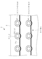
- FIG. 1 It is a figure which shows the heat-transfer-tube support structure with which an exhaust heat recovery boiler is equipped. It is a perspective view showing an antivibration support plate. It is an enlarged view which shows a heat exchanger tube support structure. It is sectional drawing which shows a heat exchanger tube support structure.
- the heat transfer tube support plate 2 is formed in a plate shape.
- the heat transfer tube support plate 2 is supported by the flue so as to be disposed along a plane substantially parallel to the vertical direction.
- the heat transfer tube support plate 2 is formed with a plurality of through holes 6- (1, 1) to 6- (m, n).
- the plurality of through holes 6- (1, 1) to 6- (m, n) are arranged in a grid. That is, the plurality of through holes 6- (1, 1) to 6- (m, n) overlap any of the plurality of parallel lines, and any straight line of the plurality of parallel lines is a plurality of through holes 6-
- the plurality of through holes 6- (1, j) to 6- (m, j) of 1, 1) to 6- (m, n) overlap. Furthermore, the plurality of through holes 6- (1, 1) to 6- (m, n) correspond to the plurality of heat transfer tubes 3- (1, 1) to 3- (m, n).
- the plurality of heat transfer tubes 3- (1, 1) to 3- (m, n) are each formed in a cylindrical shape.
- the plurality of heat transfer tubes 3- (1, 1) to 3- (m, n) are arranged along a straight line parallel to the normal direction of the heat transfer tube support plate 2, ie, parallel to the horizontal direction It is arranged along a certain straight line.
- Any of the heat transfer tubes 3- (i, j) among the plurality of heat transfer tubes 3- (1, 1) to 3- (m, n) has a plurality of through holes 6- (1, 1) to 6- ( It is supported by the heat transfer tube support plate 2 by being inserted into the through hole 6- (i, j) corresponding to the heat transfer tube 3- (i, j) of m, n).
- the anti-vibration support plate 5-j is bent to form a plurality of contact surfaces 7-1 to 7-m.
- the anti-vibration support plate 5-j is arranged such that the contact surface 7-i is in contact with the outer surface of the heat transfer tube 3- (i, j), as shown in FIG. It is joined to one side of the plate 2.
- the heat transfer tube 3- (i, j) is provided with a tube 11 and a fin 12 as shown in FIG. 3 and FIG.
- the tube 11 is formed of metal and formed in a tubular shape.
- the pipe 11 forms a flow passage 14 inside.
- the fins 12 are formed of a metal plate formed in a band shape.
- the fins 12 are joined to the tube 11 along a spiral on the outer wall of the tube 11 so that the fins 12 project outwardly from the outer wall of the tube 11.
- the heat transfer tube 3- (i, j) is formed such that the edge of the fin 12 not connected to the tube 11 is along the side surface of the cylinder.
- the curvature of the contact surface 7-i corresponding to the heat transfer pipe 3- (i, j) is along the outer edge of the fin 12 of the heat transfer pipe 3- (i, j). It is formed to be equal to the curvature of the surface.
- the anti-vibration support plate 5-j contacts the outer edges of the fins 12 of the plurality of heat transfer tubes 3- (1, j) to 3- (m, j) with the plurality of contact surfaces 7-1 to 7-m.
- the heat transfer tube support plate 2 is disposed so as to
- the heat transfer tube support structure 1 is applied to a waste heat recovery boiler.
- the exhaust heat recovery boiler includes a duct that forms a flue, and a plurality of heat transfer tube support structures 1 are disposed in the flue.
- the high temperature exhaust gas exhausted from the combustion apparatus exemplified by the boiler flows into the flue, and the heat transfer pipes 3- (1, 1) to 3- (m, n) flow paths 14 Drain the water.
- the exhaust gas flows in the vicinity of the plurality of heat transfer pipes 3- (1, 1) to 3- (m, n) as it flows through the flue.
- the exhaust gas contacts the plurality of heat transfer tubes 3- (1, 1) to 3- (m, n) when flowing near the plurality of heat transfer tubes 3- (1, 1) to 3- (m, n) By heating the plurality of heat transfer tubes 3- (1, 1) to 3- (m, n) and cooled by the plurality of heat transfer tubes 3- (1, 1) to 3- (m, n) .
- the heat transferred from the exhaust gas to the plurality of heat transfer tubes 3- (1, 1) to 3- (m, n) is transferred to the water flowing in the flow path. That is, when the plurality of heat transfer tubes 3- (1, 1) to 3- (m, n) are in contact with the exhaust gas, the heat of the exhaust gas is transferred to the water flowing in the flow path 14 Heat up.
- the heat transfer tube support structure 1 supports the heat transfer tube 3- (i, j) between the anti-vibration support plate 5-j and the edge of the through hole 6- (i, j) to support the through hole
- the clearance between the edge of 6- (i, j) and the heat transfer tube 3- (i, j) can be reduced.
- the plurality of heat transfer tubes 3- (1, 1) to 3- (m, n) receive force from the exhaust gas and vibrate, particularly when the flow velocity of the exhaust gas through the flue is sufficiently fast.
- the clearance between the edge of the through hole 6- (i, j) and the heat transfer tube 3- (i, j) is reduced Vibration is reduced.
- the heat transfer tube support structure 1 includes the plurality of vibration isolation support plates 5-1 to 5-n, whereby the edge of the through hole 6- (i, j) and the heat transfer tube 3- (i, j) And the vibration of the heat transfer tube 3- (i, j) can be reduced.
- the heat transfer tube support structure 1 reduces the vibration of the heat transfer tube 3- (i, j) so that the outside of the fin 12 of the heat transfer tube 3- (i, j) is a through hole 6- (i, j). It is possible to reduce the sliding with the edge and to prevent the fins 12 of the heat transfer tube 3- (i, j) from being worn.
- the anti-vibration support plate 5-j is formed such that the curvature of the contact surface 7-i is equal to the curvature of the surface along which the outer side of the heat transfer tube 3- (i, j) follows. 7-i can be in close contact with the outside of the heat transfer tube 3- (i, j). In the heat transfer tube support structure 1, the contact surface 7-i is in contact with the contact surface 7-i of the heat transfer tube 3- (i, j) when the contact surface 7-i adheres to the outside of the heat transfer tube 3- (i, j).
- the contact surface 7-i is in close contact with the outside of the heat transfer tube 3- (i, j), so that the heat transfer tube 3- (i , J) can be properly supported so that the heat transfer tube 3- (i, j) does not vibrate.
- the contact surface 7-i of the vibration-proof support plate 5-j has a curvature equal to the curvature of the outer surface of the heat transfer pipe 3- (i, j), so that the through hole 6-
- a flat plate is used instead of the antivibration support plate 5-j to support the heat transfer tube 3- (i, j)
- the amount of increase in the clearance between the heat transfer pipe 3- (i, j) and the through hole 6- (i, j) can be suppressed, and the sliding of the heat transfer pipe 3- (i, j) is reduced, The wear of the fins 12 can be reduced.
- the plurality of heat transfer tubes 3- (1, 1) to 3- (m, n) may be replaced with other plurality of heat transfer tubes arranged in a shape different from the lattice shape.
- a plurality of heat transfer tubes a plurality of heat transfer tubes arranged in a staggered manner are exemplified.
- the plurality of anti-vibration support plates 5-1 to 5-n are arranged to reduce the clearance between the edge of the through hole and the plurality of heat transfer tubes, and are joined to the heat transfer tube support plate 2.
- the vibration of the plurality of heat transfer tubes is reduced in the same manner as the heat transfer tube support structure 1 in the embodiment described above. Wear can be reduced.
- a plurality of other anti-vibration support plates are further joined to the surface on the back side of the surface of the heat transfer tube support plate 2 to which the plurality of anti-vibration support plates 5-1 to 5-n are joined.
- the plurality of anti-vibration support plates are similar to the plurality of anti-vibration support plates 5-1 to 5-n, and the edges of the plurality of through holes 6- (1, 1) to 6- (m, n) and the plurality of The heat transfer tubes 3- (1, 1) to 3- (m, n) are arranged to reduce their clearances.
- the heat transfer tube support structure further including such a plurality of vibration isolation support plates similarly to the heat transfer tube support structure 1 in the embodiment described above, a plurality of heat transfer tubes 3- (1, 1) to 3 The wear of-(m, n) can be reduced. Furthermore, the heat transfer tube support structure further including such a plurality of vibration isolation support plates is more effective than the heat transfer tube support structure 1 described above in comparison with the plurality of heat transfer tubes 3- (1, 1) to 3- (3 m, n) can be supported more firmly, and wear of the plurality of heat transfer tubes 3- (1, 1) to 3- (m, n) can be more reliably reduced.
- the anti-vibration support plate 5-j can be replaced with other anti-vibration support plates corresponding to the plurality of heat transfer tubes 3- (1, j) to 3- (m, j).
- the anti-vibration support plate corresponding to the heat transfer tubes 3- (i, j) of the plurality of anti-vibration support plates is between the edge of the through hole 6- (i, j) and the heat transfer tubes 3- (i, j)
- the heat transfer tube support plate 2 is joined to reduce the clearance.
- the heat transfer tube support structure reduces the vibration of the plurality of heat transfer tubes 3- (1, j) to 3- (m, j), and the plurality of heat transfer tubes 3- (1, j) to 3- The wear of (m, j) can be reduced.
- the heat transfer tube support structure 1 in the embodiment described above needs to connect the heat transfer tube support plate 2 to the heat transfer tube support plate 2 in the same number as the plurality of heat transfer tubes 3- (1, j) to 3- (m, j). There is.
- the plurality of vibration isolation support plates 5-1 to 5-n joined to the heat transfer tube support plate 2 are a plurality of heat transfer tubes 3- (1, 1, j) By being less than ⁇ 3- (m, j), it can be easily produced as compared with a heat transfer tube support structure provided with such a plurality of vibration isolation support plates.
- the heat transfer tube 3- (i, j) can be replaced with another heat transfer tube in which the fins 12 are not formed. Also at this time, the heat transfer tube support structure can reduce the sliding of the heat transfer tube with the edge of the through hole 6- (i, j), and can prevent the heat transfer tube from being worn out.
- Heat Transfer Tube Support Structure 2 Heat Transfer Tube Support Plate 3- (1, 1) to 3- (m, n) Multiple Heat Transfer Tubes 5-1 to 5-n Multiple Antivibration Support Plate 6- (1, 1) ⁇ 6- (m, n) multiple through holes 7-1 ⁇ 7-m multiple contact surfaces
Landscapes
- Engineering & Computer Science (AREA)
- Physics & Mathematics (AREA)
- Thermal Sciences (AREA)
- Mechanical Engineering (AREA)
- General Engineering & Computer Science (AREA)
- Heat-Exchange Devices With Radiators And Conduit Assemblies (AREA)
- Supports For Pipes And Cables (AREA)
Abstract
Priority Applications (4)
| Application Number | Priority Date | Filing Date | Title |
|---|---|---|---|
| MX2016005164A MX2016005164A (es) | 2013-11-13 | 2014-08-11 | Estructura de soporte de tuberia de transferencia de calor y caldera de recuperacion del calor residual. |
| US15/031,364 US20160281976A1 (en) | 2013-11-13 | 2014-08-11 | Heat transfer pipe support structure and waste heat recovery boiler |
| KR1020167010844A KR20160064162A (ko) | 2013-11-13 | 2014-08-11 | 전열관 지지구조물 및 배열회수보일러 |
| CN201480057696.XA CN105659049A (zh) | 2013-11-13 | 2014-08-11 | 传热管支撑结构物以及废热回收锅炉 |
Applications Claiming Priority (2)
| Application Number | Priority Date | Filing Date | Title |
|---|---|---|---|
| JP2013-235262 | 2013-11-13 | ||
| JP2013235262A JP6407518B2 (ja) | 2013-11-13 | 2013-11-13 | 伝熱管支持構造物および排熱回収ボイラ |
Publications (1)
| Publication Number | Publication Date |
|---|---|
| WO2015072190A1 true WO2015072190A1 (fr) | 2015-05-21 |
Family
ID=53057136
Family Applications (1)
| Application Number | Title | Priority Date | Filing Date |
|---|---|---|---|
| PCT/JP2014/071226 WO2015072190A1 (fr) | 2013-11-13 | 2014-08-11 | Structure de support de tuyau de transfert thermique et chaudière de récupération de chaleur |
Country Status (6)
| Country | Link |
|---|---|
| US (1) | US20160281976A1 (fr) |
| JP (1) | JP6407518B2 (fr) |
| KR (1) | KR20160064162A (fr) |
| CN (1) | CN105659049A (fr) |
| MX (1) | MX2016005164A (fr) |
| WO (1) | WO2015072190A1 (fr) |
Families Citing this family (2)
| Publication number | Priority date | Publication date | Assignee | Title |
|---|---|---|---|---|
| US11035615B2 (en) | 2018-08-23 | 2021-06-15 | Caterpillar Inc. | Support clip for finned tube type heat exchangers |
| KR102338706B1 (ko) | 2020-05-13 | 2021-12-13 | 주식회사 디엠티 | 배열회수보일러용 신축이음관 |
Citations (4)
| Publication number | Priority date | Publication date | Assignee | Title |
|---|---|---|---|---|
| US4285396A (en) * | 1979-01-25 | 1981-08-25 | Wachter Associates, Inc. | Steam generator tube support system |
| JPS63104882U (fr) * | 1986-12-23 | 1988-07-07 | ||
| JP2003161593A (ja) * | 2001-11-20 | 2003-06-06 | Babcock Hitachi Kk | フィン付伝熱管の取付け構造 |
| JP2013148243A (ja) * | 2012-01-17 | 2013-08-01 | Mitsubishi Heavy Ind Ltd | 熱交換器 |
Family Cites Families (5)
| Publication number | Priority date | Publication date | Assignee | Title |
|---|---|---|---|---|
| US2402209A (en) * | 1944-06-29 | 1946-06-18 | Support for finned tubes | |
| US2862693A (en) * | 1953-07-24 | 1958-12-02 | American Radiator & Standard | Support for finned tube type heat exchangers |
| JP2857440B2 (ja) * | 1990-01-16 | 1999-02-17 | バブコツク日立株式会社 | 伝熱管支持装置 |
| JP2002295989A (ja) * | 2001-03-29 | 2002-10-09 | Babcock Hitachi Kk | フィン付伝熱管およびその支持構造 |
| JP2007271157A (ja) * | 2006-03-31 | 2007-10-18 | Mitsubishi Heavy Ind Ltd | 伝熱管の支持構造 |
-
2013
- 2013-11-13 JP JP2013235262A patent/JP6407518B2/ja active Active
-
2014
- 2014-08-11 KR KR1020167010844A patent/KR20160064162A/ko not_active Application Discontinuation
- 2014-08-11 MX MX2016005164A patent/MX2016005164A/es unknown
- 2014-08-11 CN CN201480057696.XA patent/CN105659049A/zh active Pending
- 2014-08-11 US US15/031,364 patent/US20160281976A1/en not_active Abandoned
- 2014-08-11 WO PCT/JP2014/071226 patent/WO2015072190A1/fr active Application Filing
Patent Citations (4)
| Publication number | Priority date | Publication date | Assignee | Title |
|---|---|---|---|---|
| US4285396A (en) * | 1979-01-25 | 1981-08-25 | Wachter Associates, Inc. | Steam generator tube support system |
| JPS63104882U (fr) * | 1986-12-23 | 1988-07-07 | ||
| JP2003161593A (ja) * | 2001-11-20 | 2003-06-06 | Babcock Hitachi Kk | フィン付伝熱管の取付け構造 |
| JP2013148243A (ja) * | 2012-01-17 | 2013-08-01 | Mitsubishi Heavy Ind Ltd | 熱交換器 |
Also Published As
| Publication number | Publication date |
|---|---|
| KR20160064162A (ko) | 2016-06-07 |
| CN105659049A (zh) | 2016-06-08 |
| JP6407518B2 (ja) | 2018-10-17 |
| JP2015094559A (ja) | 2015-05-18 |
| US20160281976A1 (en) | 2016-09-29 |
| MX2016005164A (es) | 2016-08-08 |
Similar Documents
| Publication | Publication Date | Title |
|---|---|---|
| JP2007232355A5 (fr) | ||
| JP6357706B2 (ja) | 熱交換器 | |
| EP1996891A4 (fr) | Echangeur de chaleur pour gaz de système de recirculation des gaz d'échappement | |
| US20170299274A1 (en) | Heat exchanger | |
| JP2013011409A (ja) | 給湯装置 | |
| WO2015072190A1 (fr) | Structure de support de tuyau de transfert thermique et chaudière de récupération de chaleur | |
| JP5790973B2 (ja) | 温水装置 | |
| WO2013118527A1 (fr) | Échangeur de chaleur | |
| JP6177523B2 (ja) | ダスト除去装置を備えた排熱ボイラーおよび熱交換器 | |
| JP2015102051A (ja) | Egrクーラ | |
| JP2011185562A5 (fr) | ||
| JP3180377U (ja) | 熱交換器 | |
| JP2013061114A (ja) | 熱交換器 | |
| JP2015094559A5 (fr) | ||
| JP2014070849A (ja) | 熱交換器 | |
| WO2020110327A1 (fr) | Récupération de chaleur | |
| KR101611364B1 (ko) | 채널형 열교환기 | |
| JP6891860B2 (ja) | 伝熱管のダスト除去装置 | |
| JP5980138B2 (ja) | 伝熱管および排熱回収ボイラ | |
| KR101230499B1 (ko) | 내부핀을 구비한 전열관 | |
| JP6108107B2 (ja) | 熱交換器及び熱交換器の製造方法 | |
| JP2014105883A (ja) | フィンチューブ式熱交換装置 | |
| JP6109716B2 (ja) | フィンチューブ式熱交換器 | |
| JP5454004B2 (ja) | 熱交換器 | |
| JPWO2020027008A1 (ja) | 熱交換器 |
Legal Events
| Date | Code | Title | Description |
|---|---|---|---|
| 121 | Ep: the epo has been informed by wipo that ep was designated in this application |
Ref document number: 14862492 Country of ref document: EP Kind code of ref document: A1 |
|
| WWE | Wipo information: entry into national phase |
Ref document number: MX/A/2016/005164 Country of ref document: MX |
|
| WWE | Wipo information: entry into national phase |
Ref document number: 15031364 Country of ref document: US |
|
| ENP | Entry into the national phase |
Ref document number: 20167010844 Country of ref document: KR Kind code of ref document: A |
|
| NENP | Non-entry into the national phase |
Ref country code: DE |
|
| 122 | Ep: pct application non-entry in european phase |
Ref document number: 14862492 Country of ref document: EP Kind code of ref document: A1 |