WO2015072185A1 - 商品払出装置 - Google Patents
商品払出装置 Download PDFInfo
- Publication number
- WO2015072185A1 WO2015072185A1 PCT/JP2014/070121 JP2014070121W WO2015072185A1 WO 2015072185 A1 WO2015072185 A1 WO 2015072185A1 JP 2014070121 W JP2014070121 W JP 2014070121W WO 2015072185 A1 WO2015072185 A1 WO 2015072185A1
- Authority
- WO
- WIPO (PCT)
- Prior art keywords
- product
- storage passage
- pedal
- product storage
- sold
- Prior art date
- Legal status (The legal status is an assumption and is not a legal conclusion. Google has not performed a legal analysis and makes no representation as to the accuracy of the status listed.)
- Ceased
Links
Images










Classifications
-
- G—PHYSICS
- G07—CHECKING-DEVICES
- G07F—COIN-FREED OR LIKE APPARATUS
- G07F11/00—Coin-freed apparatus for dispensing, or the like, discrete articles
- G07F11/02—Coin-freed apparatus for dispensing, or the like, discrete articles from non-movable magazines
- G07F11/04—Coin-freed apparatus for dispensing, or the like, discrete articles from non-movable magazines in which magazines the articles are stored one vertically above the other
-
- G—PHYSICS
- G07—CHECKING-DEVICES
- G07F—COIN-FREED OR LIKE APPARATUS
- G07F11/00—Coin-freed apparatus for dispensing, or the like, discrete articles
- G07F11/02—Coin-freed apparatus for dispensing, or the like, discrete articles from non-movable magazines
- G07F11/04—Coin-freed apparatus for dispensing, or the like, discrete articles from non-movable magazines in which magazines the articles are stored one vertically above the other
- G07F11/16—Delivery means
- G07F11/24—Rotary or oscillatory members
-
- G—PHYSICS
- G07—CHECKING-DEVICES
- G07F—COIN-FREED OR LIKE APPARATUS
- G07F9/00—Details other than those peculiar to special kinds or types of apparatus
- G07F9/02—Devices for alarm or indication, e.g. when empty; Advertising arrangements in coin-freed apparatus
- G07F9/026—Devices for alarm or indication, e.g. when empty; Advertising arrangements in coin-freed apparatus for alarm, monitoring and auditing in vending machines or means for indication, e.g. when empty
-
- G—PHYSICS
- G07—CHECKING-DEVICES
- G07F—COIN-FREED OR LIKE APPARATUS
- G07F9/00—Details other than those peculiar to special kinds or types of apparatus
- G07F9/10—Casings or parts thereof, e.g. with means for heating or cooling
Definitions
- the present invention relates to a commodity dispensing apparatus, and more particularly, to a vending machine that sells commodities such as canned beverages and plastic bottled beverages, for example, commodity dispensing that appropriately unloads commodities stored in a commodity storage passage It relates to an apparatus.
- a commodity storage rack is provided in a commodity storage inside a main body cabinet which is a vending machine main body.
- the product storage rack has a product storage passage extending along the vertical direction, and a product unloading device disposed in the lower part of the product storage passage.
- the commodity carry-out device is configured to include a lower pedal member and an upper pedal member.
- the lower pedal member and the upper pedal member are linked to an AC solenoid, which is an actuator, via a link member, and appropriately moved to and from the product storage passage when the AC solenoid is energized.
- the upper pedal member is the product storage passage via the link member when the AC solenoid is energized.
- the AC solenoid By moving to the second position and contacting the second lowest product, the downward movement of the product and the product stored above the product is restricted.
- the lower pedal member retracts from the product storage passage, the lowermost product is carried out only downward, and the lower pedal member is pushed when the product slips through the lower pedal member. It moves forward into the product storage passage by the biasing force of the spring.
- Patent No. 2749917 gazette
- the product delivery apparatus proposed in Patent Document 1 can be applied to a product storage rack provided with an even number of product storage passages adjacent to each other in front and back, but for a product storage rack provided with an odd number of product storage passages It could not be used as an individual product delivery device.
- the product delivery device is provided with two types of product delivery devices having different widths corresponding to the types of product storage racks, that is, for products with relatively small maximum widths and products with relatively large maximum widths. It is general to mount a commodity unloading device having a width corresponding to the maximum width of the commodity stored in the rack on the commodity storage rack.
- the present invention can provide a product dispensing apparatus capable of reducing manufacturing costs and flexibly responding to the number of product storage passages adjacent to each other. To aim.
- the commodity delivery apparatus is applied to one commodity storage passage which extends along the vertical direction and stores the input commodity along its own extension direction.
- the standby state while restricting the downward movement of the goods stored in the one goods storage passage, when driving, the lowermost goods stored in the one goods storage passage are lowered.
- one other product that extends along the up-and-down direction adjacent to the one product storage passage and stores the input product along its own extension direction. It applies to the storage passage, restricts the downward movement of the goods stored in the other product storage passage in the standby state, while it controls the largest one stored in the other product storage passage when it is driven.
- a product delivery device capable of holding the other product delivery device to be carried out back-to-back with each other, wherein the one product delivery device is provided with a drive source for itself and the other product delivery device, and a delivery command.
- the apparatus further comprises: a driving force application means for selectively selecting oneself and the other commodity carrying out device according to the delivery command and applying a driving force from the drive source.
- the present invention is characterized in that, in the commodity delivery apparatus, the drive source is common to the one commodity delivery apparatus and the other commodity delivery apparatus.
- the present invention is characterized in that, in the above-mentioned commodity delivery apparatus, the drive source is a direct current motor.
- the one commodity unloading apparatus is swingably disposed in a mode of advancing and retreating to the one commodity storage passage, and is biased by biasing means in a normal state.
- the one product storage passage resists the biasing force of the biasing means.
- the other commodity discharge device is swingably disposed in a manner to move forward and backward to the other commodity storage passage, and is biased by the biasing means in a normal state.
- the other product storage passage is resisted against the biasing force of the biasing means. Having a sellout detection lever that moves more backward And features.
- the one commodity delivery apparatus is turned off when the sold-out detection lever retreats from the one commodity storage passage, while the sold-out detection lever is A sellout detection switch that turns on when the advance movement to the one product storage passage is made and detects that the one product storage passage is sold out, and the other product delivery device is equipped When the sold-out detection lever is retreated from the other product storage passage, it is in the OFF state, and when the sold-out detection lever provided in the other product unloading device is advanced to the other product storage passage And a sell-out detection switch for detecting that the other product storage passage is sold out.
- the apparatus and the other product delivery device are alternatively selected to provide the driving force application means for applying the driving force from the drive source, the number of drive sources is reduced relative to the number of product delivery devices. And the manufacturing cost can be reduced. Moreover, since one of the product delivery devices is provided with the drive source and the driving force application means, only one of the product delivery devices can be used.
- the present invention can be used not only for product storage devices provided with even-numbered product storage passages lined up in front and back, but also for product storage devices provided with odd-numbered product storage passages lined up in front and back. Therefore, while being able to attain reduction of manufacturing cost, it is effective in the ability to respond flexibly according to the number of goods storage passages adjacent to back and forth.
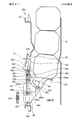
- FIG. 1 is a cross-sectional side view showing a case where an internal structure of a vending machine to which a commodity delivery apparatus according to an embodiment of the present invention is applied is viewed from the right side.
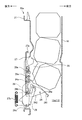
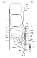
- FIG. 2 is a side view showing the commodity delivery apparatus shown in FIG. 1 as viewed from the left side.
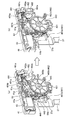
- FIG. 3 is a perspective view showing the commodity delivery apparatus shown in FIG. 1 as viewed from the rear left side.
- FIG. 4: is explanatory drawing which isolate
- FIG. 5 is an explanatory view schematically showing a main portion of the first unloading mechanism (one commodity unloading device) shown in FIGS. 2 to 4 as viewed from the left side.
- FIG. 6 is an explanatory view schematically showing a main portion of the first unloading mechanism shown in FIGS. 2 to 4 as viewed from the left side.
- FIG. 7 is an explanatory view schematically showing a main portion of the first unloading mechanism shown in FIGS. 2 to 4 as viewed from the left side.
- FIG. 8 is a perspective view showing the main part of the drive unit in the first unloading mechanism as viewed from the rear left side.
- FIG. 9 is an exploded perspective view of the main part of the drive unit in the first unloading mechanism.
- FIG. 10 is a rear view showing the first unloading mechanism as viewed from the back side.
- FIG. 11 is a block diagram schematically showing a characteristic control system of the drive unit.
- FIG. 12 is an enlarged perspective view showing the main part of the first unloading mechanism, in which (a) shows a state in which the sellout detection lever has moved backward, and (b) shows a state in which the sellout detection lever has advanced Is shown.
- FIG. 13 is an explanatory view schematically showing a case where the main part of the second carry-out mechanism (the other product carry-out device) shown in FIGS. 2 to 4 is viewed from the left side.
- FIG. 14 is an explanatory view schematically showing a case where the main part of the second carry-out mechanism shown in FIGS. 2 to 4 is viewed from the left side.
- FIG. 15 is an explanatory view schematically showing a case where the main part of the second carry-out mechanism shown in FIGS.
- FIG. 16 is an enlarged perspective view showing the main part of the first unloading mechanism, wherein (a) shows a state in which the sold-out detection lever provided in the second unloading mechanism has moved backward, and (b) shows 2 shows a state in which the sold-out detection lever provided in the delivery mechanism has advanced.
- FIG. 17 is a flowchart showing the contents of the carry-out control process carried out by the carry-out control unit of the commodity delivery apparatus.
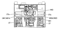
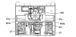
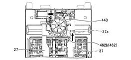
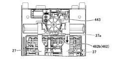
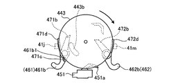
- FIG. 18A is an explanatory view showing the operation state when the motor is driven to rotate in the normal direction in FIG. 17 as viewed from the rear.
- FIG. 18-2 is an explanatory view showing the operation state when the motor is driven to rotate in the forward direction in FIG.
- FIG. 18-3 is an explanatory view showing the operation state when the motor is driven to rotate in the forward direction in FIG. 17 as viewed from the rear.
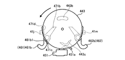
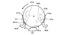
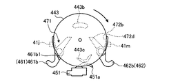
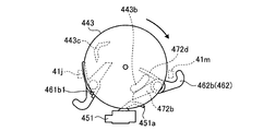
- FIG. 19A is an explanatory view showing the operation state of the output gear when the motor is driven to rotate in the forward direction in FIG. 17 as viewed from the rear.
- FIG. 19-2 is an explanatory view showing the operation state of the output gear when the motor is driven to rotate in the forward direction in FIG. 17 as viewed from the rear.
- FIG. 19-3 is an explanatory view showing the operation state of the output gear when the motor is driven to rotate in the forward direction in FIG. 17 as viewed from the rear.
- FIG. 20A is an explanatory view showing the operation state when the motor is reversely driven in FIG.
- FIG. 20-2 is an explanatory view showing the operation state when the motor is reversely driven in FIG. 17 as viewed from the rear.
- FIG. 20-3 is an explanatory view showing the operation state when the motor is reversely driven in FIG. 17 as viewed from the rear.
- FIG. 21A is an explanatory view showing the operation state of the output gear in the case of reversely driving the motor in FIG. 17 as viewed from the rear.
- FIG. 21B is an explanatory view showing the operation state of the output gear when the motor is reversely driven in FIG. 17 as viewed from the rear.
- FIG. 21-3 is an explanatory view showing the operation state of the output gear when the motor is reversely driven in FIG. 17 as viewed from the rear.
- FIG. 22 is a perspective view showing a modification of the embodiment of the present invention.
- FIG. 1 is a cross-sectional side view showing a case where an internal structure of a vending machine to which a commodity delivery apparatus according to an embodiment of the present invention is applied is viewed from the right side.
- the vending machine illustrated here is for selling a product in a cooled or heated state, and is configured to include a main body cabinet 1, an outer door 2 and an inner door 3.
- the main body cabinet 1 is configured in a rectangular shape whose front surface is opened by combining a plurality of steel plates as appropriate, and has a commodity storage case 4 of a heat insulation structure inside thereof.
- the outer door 2 is for covering the front opening of the main body cabinet 1 and is disposed at one edge of the main body cabinet 1 so as to be openable and closable. Display window, commodity selection button, bill insertion slot, coin insertion slot, return lever, integrated indicator, coin return slot, commodity outlet 2a, etc. are required on the front of this outer door 2 when selling commodities etc. Things are provided.
- the inner door 3 is a heat insulating door divided into upper and lower halves for covering the front opening of the product storage case 4, and the upper heat insulating door is at one side edge of the outer door 2 at a position inside the outer door 2.
- the lower heat insulating door is disposed at one side edge of the main body cabinet 1 so as to be able to open and close.
- a commodity discharge port 3 a for carrying the commodity out of the commodity storage 4 is provided.
- a commodity shooter 5 is provided inside the commodity storage 4, and a temperature control unit is provided in a region (hereinafter also referred to as "heat exchange region") below the commodity shooter 5.
- the product storage rack 10 is disposed in an area (hereinafter, also referred to as a "product storage area”) above the product shooter 5 while the 6 is disposed.
- the commodity shooter 5 is a plate-like member for guiding the commodity carried out of the commodity storage rack 10 to the commodity outlet 3a of the inner door 3, and is disposed in a manner to gradually incline downward toward the front side There is. Although not clearly shown in the figure, the commodity shooter 5 is provided with a large number of vent holes (not shown) for communicating between the heat exchange area and the commodity storage area.
- the temperature control unit 6 is for maintaining the internal atmosphere of the product storage case 4 at a desired temperature state, and includes an evaporator 6a of a refrigeration cycle, an electric heater 6b, and a blower fan 6c.
- this temperature control unit 6 for example, when the blower fan 6c is driven in a state where the refrigeration cycle is operated, the air cooled in the evaporator 6a is fed upward through the vent holes of the product shooter 5, so the product storage area Can be maintained at a low temperature.
- the blower fan 6c is driven in a state in which the electric heater 6b is energized, the air heated by the electric heater 6b is supplied upward through the vent holes of the product shooter 5, so the product storage area is maintained at high temperature. be able to.
- the compressor, the condenser and the expansion valve of the refrigeration cycle are disposed in the machine room 7 which is not shown in the figure but is outside the commodity storage case 4.
- the product storage racks 10 are arranged in three rows in the front and rear direction, and are configured in a serpentine shape along the vertical direction by arranging the passage components 12 between the pair of base side plates 11.
- a plurality of (two in the illustrated example) product storage channels 13 are provided, and a plurality of products are stored inside the product storage channels 13 in an upside-down posture along the vertical direction.
- the passage components 12 are appropriately disposed to face each other on the front side and the rear side of the commodity storage passage 13 and are fixed to the base side plate 11.
- two commodity storage passages 13 are provided adjacent to each other in the front and back direction.
- the front product storage passage 13 is also referred to as a first product storage passage 13a
- the rear product storage passage 13 is also referred to as a second product storage passage 13b.
- the passage component 12 is provided with a flapper which is not explicitly shown in the figure.
- the flapper is pivotally disposed in the passage component 12 in such a manner as to move forward and backward with respect to the commodity storage passage 13.
- the flapper is urged by a coil spring (not shown) to move forward into the product storage passage 13 in a normal state. Then, by coming into contact with the product passing through the product storage passage 13, the self moves backward along the meandering product storage passage 13 against the biasing force of the coil spring to correct the posture of the product. .
- the top tray 14 is provided in the upper part of the product storage passage 13 and the product delivery device 20 is provided in the lower part of the product storage passage 13.
- the top tray 14 is configured by bending a flat sheet metal, and is disposed between the base side plates 11 in a manner of being inclined gradually downward from the front to the rear.
- the upper surface of the top tray 14 as described above constitutes a commodity guiding passage 15 for guiding the commodity introduced through the inlet to the commodity storage passage 13.
- FIG. 2 to 4 respectively show the commodity delivery apparatus 20 shown in FIG. 1, and FIG. 2 is a side view showing the case viewed from the left, and FIG. 3 is a perspective view showing the case viewed from the left rear 4 is an explanatory view in which the components of the commodity delivery apparatus 20 are separated.
- the commodity delivery apparatus 20 includes one commodity unloading device (hereinafter also referred to as a first ejection mechanism) 20a and the other commodity ejection device (hereinafter also referred to as a second ejection mechanism). 20b, and the first carry-out mechanism 20a and the second carry-out mechanism 20b are configured to be held back to back.
- a first ejection mechanism the commodity unloading device
- a second ejection mechanism the other commodity ejection device
- FIGS. 5 to 7 are explanatory views schematically showing the main part of the first unloading mechanism 20a shown in FIGS. 2 to 4 as viewed from the left side.
- the structure of the first unloading mechanism 20a will be described using FIG. 5 to FIG. 7 as appropriate.
- the first carry-out mechanism 20a is applied to the first product storage passage 13a, and is disposed below the first product storage passage 13a.
- the first unloading mechanism 20a controls the behavior of the product between the opposing passage width defining plate 16 to store the product in the first product storage passage 13a in the standby state while driving the product.
- a base member 21 is provided which functions to carry out corresponding products one by one to the product shooter 5.
- the base member 21 is formed by cutting and bending a steel plate, and is disposed in such a manner that the surface of the base member 21 faces the passage width determining plate 16, and the insertion hole 22 is formed in the middle portion thereof. It is formed.
- the insertion hole 22 is a rectangular through opening. Further, side walls 21 a are formed on both sides of the base member 21 by being bent.
- a first rocking support shaft 24 a and a second rocking support shaft 25 a are mounted on the pair of left and right bearing pieces 23 provided on both sides of the insertion hole 22 of the base member 21.
- the first rocking support shaft 24 a is a shaft-like member disposed in a manner to extend along a substantially horizontal direction, and supports the lower pedal member 24 at an intermediate portion thereof.
- the second swing support shaft 25a is a shaft-like member disposed extending substantially horizontally along the upper side of the first swing support shaft 24a, and the upper pedal is provided at the middle portion thereof. The member 25 is supported.
- the lower pedal member 24 is a plate-like member, and is disposed in such a manner that it can be pivoted about the axis of the first pivoting support shaft 24a by inserting the first pivoting support shaft 24a in the base end portion. It is done.
- the tip end portion of the lower pedal member 24 extends outward in the radial direction of the first rocking support shaft 24a, and when rocked about the axis of the first rocking support shaft 24a, through the insertion hole 22 It is possible to move back and forth to the first product storage passage 13a. That is, the lower pedal member 24 is disposed swingably in such a manner as to move forward and backward with respect to the first product storage passage 13a.
- a lower pedal member spring (not shown) is interposed between the lower pedal member 24 and the base member 21.
- the lower pedal member spring always biases the lower pedal member 24 in the advancing movement direction with respect to the first product storage passage 13a.
- the lower pedal member 24 includes a plate-like pedal body portion 241 and a pair of guide portions 242.
- the pair of guide portions 242 is provided on the back side of the pedal body 241.
- the respective guides 242 are plate-like members extending along the vertical direction, and are formed to face each other.
- Guide grooves 243 are formed on opposing surfaces of the guide portions 242 facing each other.
- the guide groove 243 is located at the lowermost position in the state (shown in FIG. 5) in which the lower pedal member 24 is disposed at the advanced position moved forward with respect to the first product storage passage 13a.
- a state (shown in FIG. 7) in which the lower pedal member 24 is disposed at the most retracted position with respect to the first product storage passage 13a with the insertion portion 243a into which the pedal operation shaft 29a of the stopper member 29 is inserted.
- the first guiding portion 243b is separated from the fitting portion 243a with respect to the base member 21 in a state where the lower pedal member 24 is disposed at a position (advanced position) where the lower pedal member 24 is most advanced and moved with respect to the first product storage passage 13a.
- the guide portion 242 is formed so as to be inclined obliquely upward so as to approach the base member 21 and reach the contact portion 243 d.
- the second guide portion 243c is separated from the contact portion 243d with respect to the base member 21 in a state in which the lower pedal member 24 is disposed at a position (advanced position) at which the lower pedal member 24 is moved most to the first product storage passage 13a. It is formed in the guide part 242 in the aspect which inclines diagonally downward and reaches the insertion part 243a.
- the radial outward length of the lower pedal member 24 from the first swing support shaft 24a is as shown in the figure when it is positioned at the most advanced position (advanced position) with respect to the first product storage passage 13a. As also shown in FIG. 5, the length is set such that a gap smaller than the maximum width of the product having a smaller maximum width with the passage width defining plate 16 can be secured.
- the upper pedal member 25 is a plate-like member, and by inserting the second rocking support shaft 25a at the base end, the base member can be rocked about the axis of the second rocking support shaft 25a. It is arranged at 21.
- the tip of the upper pedal member 25 extends outward in the radial direction of the second rocking support shaft 25a, and when it is swung around the axis of the second rocking support shaft 25a, the insertion hole is formed. It is possible to move back and forth to the first product storage passage 13 a through 22. That is, the upper pedal member 25 is swingably disposed in such a manner as to move forward and backward with respect to the first product storage passage 13a.
- An upper pedal member spring (not shown) is interposed between the upper pedal member 25 and the base member 21.
- the upper pedal member spring always biases the upper pedal member 25 in the backward movement direction with respect to the first product storage passage 13a.
- the upper pedal member 25 is provided with a pressing inclined surface 251, a recess 252, a stopper contact portion 253, and a protrusion 254.
- the pressing inclined surface 251 is provided at the front end portion of the upper pedal member 25. When the upper pedal member 25 is moved backward with respect to the first product storage passage 13a, the pressing inclined surface 251 is directed to the first product storage passage 13a. It is a curved inclined surface formed in a gradually decreasing manner.
- the recess 252 is provided on the back side of the upper pedal member 25 and is a single recess extending along a substantially horizontal direction formed in such a manner as to open on both side surfaces of the upper pedal member 25.
- the stopper abutting portion 253 is a portion on which a stopper pin 28a described later abuts, and is provided in such a manner as to be inclined above the recess 252 on the back surface of the upper pedal member 25.
- the protruding portion 254 is provided in a manner of protruding toward the first product storage passage 13 a at the base end portion of the upper pedal member 25.
- the upper pedal member 25 is biased to move backward to the first product storage passage 13a by the biasing force of the upper pedal member spring, but the stopper pin 28a abuts on the recess 252 to store the first product.
- the initial position is set in a state of retreating movement with respect to the passage 13a.
- Such an upper pedal member 25 passes through the second swing support shaft 25a in a state (state shown in FIG. 7) positioned at a position (advanced position) which has advanced most to the first product storage passage 13a. It is in an inclined state forward with respect to the vertical plane.
- the length of the radially outward direction from the second swing support shaft 25a of the upper pedal member 25 is greater than the maximum width of the product having a smaller maximum width with the passage width defining plate 16 in the above-described forward inclined state. The length is set so as to secure a small gap.
- a bearing 26 is provided on the base member 21.
- the bearing portion 26 guides movement of the pedal link member 27 in the vertical direction, and is formed to extend in the vertical direction, and one end thereof is at the upper end edge of the insertion hole 22. It is attached, and the other end is attached to the lower end edge of the insertion hole 22 and provided so as to cross the insertion hole 22 longitudinally.
- the bearing portion 26 is made of a resin material, and includes a second rocking support shaft insertion hole 261, a first rocking support shaft insertion hole 262, a stopper pin insertion hole 263, and a pedal stopper pin support groove 264. And stopper support holes 265.
- the second swing support shaft insertion hole 261 is a hole for inserting the second swing support shaft 25 a and supporting the second swing support shaft 25 a.
- the first rocking support shaft insertion hole 262 is a hole for inserting the first rocking support shaft 24 a and supporting the first rocking support shaft 24 a.
- the first rocking support shaft insertion hole 262 is formed below the second rocking support shaft insertion hole 261.
- the stopper pin insertion hole 263 is a hole slidably supporting a stopper pin 28a described later, and the extension length in the vertical direction is larger than the diameter of the axially formed stopper pin 28a. It is formed. Therefore, the stopper pin insertion hole 263 allows movement of the stopper pin 28 a in the vertical direction, and in the bearing portion 26, a portion where the upper end portion and the second swing support shaft insertion hole 261 are formed. It is provided in the part which becomes approximately middle between and.
- the pedal stopper pin support groove 264 is a hole slidably supporting a pedal stopper pin 28b described later, and extends in the vertical direction in comparison with the diameter of the axially formed pedal stopper pin 28b. Is formed to be large. Therefore, the pedal stopper pin support groove 264 allows movement of the pedal stopper pin 28b in the vertical direction, and in the bearing portion 26, a portion where the first swing support shaft insertion hole 262 is formed; It is provided in the part which becomes approximately middle with a lower end part.
- the stopper support hole 265 is a hole for supporting a stopper shaft 28 c described later, and is formed at the lower end portion of the bearing portion 26.
- a stopper pin 28a is provided between the one bearing piece 23 and the bearing portion 26, a stopper pin 28a, a pedal stopper pin 28b and a stopper shaft 28c.
- the stopper pin 28 a is a shaft-like member disposed along a substantially horizontal direction between one bearing piece 23 and the bearing portion 26, and one end portion thereof is a stopper pin insertion hole (not shown) of the bearing piece 23. And the other end portion is inserted into the stopper pin insertion hole 263 of the bearing 26.
- the stopper pin 28 a is coupled to the pedal link member 27, and can move in the vertical direction inside the stopper pin insertion hole 263 as the pedal link member 27 moves in the vertical direction.
- the stopper pin 28 a is in contact with the recess 252 of the upper pedal member 25 at the initial position.
- the pedal stopper pin 28 b is an axial member disposed along the substantially horizontal direction between the one bearing piece 23 and the bearing portion 26, and one end thereof is a pedal stopper pin supporting groove of the bearing piece 23 (see FIG. The other end is inserted into the pedal stopper pin support groove 264 of the bearing 26.
- the pedal stopper pin 28 b is coupled to the pedal link member 27, and can be moved along the vertical direction inside the pedal stopper pin support groove 264 as the pedal link member 27 moves in the vertical direction. is there.
- the circumferential surface of the pedal stopper pin 28b abuts against the inner circumferential surface of the pedal stopper pin support groove 264 when the pedal link member 27 is moved in the vertical direction.
- the stopper shaft 28 c is a shaft-like member disposed substantially horizontally between the one bearing piece 23 and the bearing portion 26, and supports the rotation stopper member 29 at an intermediate portion thereof.
- the rotation stopper member 29 is disposed between the one bearing piece 23 and the bearing portion 26 in such a manner that the stopper shaft 28c is inserted through the base end portion and can be pivoted around the axis of the stopper shaft 28c. It is done.
- the distal end portion of the rotation stopper member 29 extends outward in the radial direction of the stopper shaft 28c, and when it pivots around the axis of the stopper shaft 28c, it passes through the insertion hole 22 to the first product storage passage 13a. It is possible to move back and forth.
- the rotation stopper member 29 has a pedal operation shaft 29a at its tip.
- the pedal operation shaft 29 a is a shaft-like member disposed substantially in the horizontal direction, and both end portions thereof are fitted in the guide grooves 243 of the lower pedal member 24.
- a pedal operating member spring (not shown) is interposed between the rotation stopper member 29 and the base member 21.
- the pedal operation member spring always urges the rotation stopper member 29 in a direction in which the rotation stopper member 29 is advanced and moved with respect to the first product storage passage 13a.
- Such a rotation stopper member 29 is biased by a pedal operation member spring in a direction to move forward with respect to the first product storage passage 13a, and a pedal stopper is provided at a predetermined portion on the back side of the rotation stopper member 29.
- the movement in the backward movement direction is restricted by the contact of the pin 28b, and the initial position in the state of advancing and moving with respect to the first product storage passage 13a is set.
- both ends of the pedal operation shaft 29 a of the rotation stopper member 29 are positioned at the fitting portion 243 a of the guide groove 243.
- the initial position is set at a position at which the first product storage passage 13a has advanced.
- the pedal link member 27 is a long plate-like member extending along the vertical direction, and has a claw portion 27 a formed by bending a part of the upper portion forward. Although details will be described later, the pedal link member 27 is movable along the vertical direction.
- a link spring 27 b is interposed between the pedal link member 27 and the base member 21.
- the link spring 27 b always biases the pedal link member 27 downward.
- a second link spring is interposed between the pedal link member 27 and the base member 21.
- the second link spring has one end engaged with an engagement hole formed at the lower end of the pedal link member 27, and the other end engaged with the stopper shaft 28c.
- the second link spring normally prevents the engagement between the pedal link member 27 and the pedal stopper pin 28b from being released by its own elastic force.
- the stopper pin 28a is disposed at the lower end portion of the stopper pin insertion hole 263, and the pedal stopper is disposed at the lower end portion of the pedal stopper pin support groove 264.
- the pin 28b will be placed.
- the recess 252 of the upper pedal member 25 disposed at the retracted position abuts against the stopper pin 28a.
- the rotation stopper member 29 disposed at the advanced position abuts on the pedal stopper pin 28b, and the backward movement of the rotation stopper member 29 is restricted.
- the pedal operation shaft 29a of the rotation stopper member 29 disposed at the advanced position is inserted into the fitting portion 243a of the lower pedal member 24, whereby the backward movement of the lower pedal member 24 disposed at the advanced position is It is regulated.
- the stopper pin 28a is disposed at the upper end portion of the stopper pin insertion hole 263, as shown in FIG. Also, the pedal stopper pin 28 b is disposed at the upper end portion of the pedal stopper pin support groove 264.
- the stopper contact portion 253 of the upper pedal member 25 abuts on the stopper pin 28a, the backward movement of the upper pedal member 25 is restricted, and the upper pedal member resists the biasing force of the upper pedal member spring. 25 moves forward and is placed at the exit position.
- the first carry-out mechanism 20a having the above configuration includes the drive unit 40 in addition to the above configuration.
- 8 and 9 show the main part of the drive unit 40 in the first carry-out mechanism 20a, respectively, and FIG. 8 is a perspective view showing a case seen from the rear left side, and FIG. 9 is an exploded perspective view.
- FIG. 10 is a rear view showing the first unloading mechanism 20a viewed from the rear side, and some of the components are removed for the convenience of description.
- FIG. 11 is a block diagram schematically showing a characteristic control system of the drive unit 40. As shown in FIG.
- the drive unit 40 is disposed on the back side of the base member 21 above the second rocking support shaft 25 a and in a region directly above the bearing portion 26.
- the drive unit 40 includes a unit base 41 attached to the back of the base member 21.
- the unit base 41 is formed of, for example, a resin material or the like, and is formed in a box shape whose rear surface is open.
- a rectangular base opening 41 a is formed on the front surface of the unit base 41 at a portion corresponding to the upper opening 21 b (see FIG. 4) provided in the base member 21.
- the unit cover 41 is closed by the attachment of a unit cover 42 made of resin to form an accommodation space between the unit base 41 and the unit cover 42. In this manner, the motor 43, the gear member 44, the switch member 45, the link lever member 46, the arm member 47, and the sold-out link lever member 48 are housed in the housing space formed by the unit base 41 and the unit cover 42. ing.
- the motor 43 is a drive source, and is a direct-current motor capable of rotating in the forward and reverse directions according to a command given from the carry-out control unit 50 which is control means.
- the motor 43 is disposed in a state of being held by the motor holding portion 41 b of the unit base 41.
- the carry-out control unit 50 controls the operation of the drive unit 40 in accordance with the program and data stored in the memory 51, and can communicate with the vending machine control unit 100 which controls the sales operation of the vending machine. It is a thing.
- the gear member 44 includes a helical gear 441, an intermediate gear 442 and an output gear 443.
- the helical gear 441 has a disk shape, and a hole (not shown) is formed in the central portion, and a gear portion 441a formed of a plurality of teeth is formed on the circumferential surface.
- the helical gear 441 is formed around the axis of the first gear shaft 41c by inserting the first gear shaft 41c of the unit base 41 through the hole in a state where the gear portion 441a is in mesh with the output shaft 43a of the motor 43. It is rotatably disposed.
- the intermediate gear 442 includes a disk-shaped first intermediate gear 442 a and a disk-shaped second intermediate gear 442 b having a diameter smaller than that of the first intermediate gear 442 a.
- the first intermediate gear 442a has a hole (not shown) formed at the center and a gear portion 442a1 formed of a plurality of teeth on the circumferential surface.
- the second intermediate gear 442b is located on the rear surface side of the first intermediate gear 442a, and is provided such that its center coincides with the center of the first intermediate gear 442a.
- a gear portion 442b1 formed of a plurality of teeth is also formed on the circumferential surface of the second intermediate gear 442b.
- the intermediate gear 442 is configured such that the second gear shaft 41d of the unit base 41 is inserted through the hole in a state where the gear portion 442b1 of the first intermediate gear 442a meshes with the gear portion 441a of the helical gear 441.
- the two-gear shaft 41d is disposed rotatably about the axis.
- the output gear 443 has a disk shape having a diameter larger than that of the helical gear 441 and the intermediate gear 442.
- a gear portion 443a formed of a plurality of teeth is also formed on the circumferential surface of the output gear 443. Further, although not clearly shown in the figure, at the center of the output gear 443 is formed an axial portion projecting forward. Further, on the front face of the output gear 443, an action piece 443 b and a pressing piece 443 c are formed (both are shown in FIG. 10).
- the action piece 443b has an arc shape and is formed in such a manner as to project forward.
- the action piece 443b is formed such that its arc-like length is large enough to hold the state after the pedal link member 27 (37) is moved upward.
- the action piece 443b which will be described in detail later, is disposed in a region not in contact with the contact 451a of the carrier switch 451 constituting the switch member 45 when it moves by the rotation of the output gear 443.
- the pressing piece 443c has a substantially V shape when viewed from the rear, and is formed in a manner of projecting forward in a region opposite to the action piece 443b.
- the pressing piece 443c is formed such that the size of the protrusion projecting forward is smaller than that of the action piece 443b.
- Such an output gear 443 is formed by inserting the shaft-like portion into the shaft hole 41e formed in the unit base 41 in a state where the gear portion 443a meshes with the gear portion 442b1 of the second intermediate gear 442b. It is disposed rotatably around the axis of.
- the switch member 45 has a carrier switch 451, one sold-out detection switch (hereinafter also referred to as a first sold-out detection switch) 452 corresponding to the first unloading mechanism 20 a, and the other sold-out detection corresponding to the second unloading mechanism 20 b.
- a switch hereinafter, also referred to as a second sold-out detection switch 453 is provided.
- the carrier switch 451 is a so-called push switch and includes a contactor 451a.
- the carrier switch 451 is disposed on the unit base 41 in a state of being held by the carrier switch holding portion 41 f slightly below the area where the output gear 443 is disposed.
- the carrier switch 451 is turned on when the contact 451a is pressed, and is given as an on signal to that effect to the carry-out control unit 50, while it is turned off when the contact 451a is not pressed. ing.
- the first sold-out detection switch 452 is a so-called push-type switch, and includes a contact 452a.
- the first sold-out detection switch 452 is disposed on the unit base 41 in a state of being held by the first sold-out detection switch holding unit 41g.
- the first sold-out detection switch 452 is turned on when the contact 452a is pressed, and supplies that effect as an on signal to the carry-out control unit 50, while the contact 452a is not pressed, It is off.
- the second sold-out detection switch 453 is a so-called push-type switch, and includes a contact 453a.
- the second sold-out detection switch 453 is disposed on the unit base 41 in a state of being held by the second sold-out detection switch holding unit 41 h adjacent to the right side of the first sold-out detection switch holding unit 41 g.
- the second sold-out detection switch 453 is turned on when the contact 453a is pressed, and supplies that effect as an on signal to the carry-out control unit 50, while the contact 453a is not pressed, It is off.
- the link lever member 46 is configured to include a first link lever 461 and a second link lever 462.
- the first link lever 461 is formed of, for example, a resin material, and a through hole 461a1 is formed in the base end 461a.
- the first link lever 461 has a hook shape that is curved obliquely upward to the right after the distal end portion 461b extends obliquely downward to the right from the proximal end portion 461a. Further, a projecting piece 461b1 that protrudes toward the rear is formed at the tip end portion 461b of the first link lever 461.
- the second link lever 462 is formed of, for example, a resin material, and a through hole 462a1 is formed in the base end 462a.
- the second link lever 462 has a hook shape that is curved obliquely leftward and upward after the distal end portion 462b extends obliquely downward and leftward from the proximal end portion 462a. Further, a projecting piece (not shown) which protrudes forward is formed at the tip end portion 462 b of the second link lever 462.
- the arm member 47 includes a first arm 471 and a second arm 472.
- the first arm 471 is, for example, a flat plate made of a resin material, and includes a first base 471a, a first contact portion 471b, a first acting portion 471c, and a first locking portion 471d. .
- the first base 471a has a through hole 471a1.
- the through hole 471 a 1 has substantially the same inner diameter as the through hole 461 a 1 formed in the proximal end 461 a of the first link lever 461.
- the first contact portion 471 b is an elongated portion that extends obliquely upward to the left from the upper portion of the first base portion 471 a.
- the first action portion 471c is a portion that protrudes obliquely downward to the right from the lower portion of the first base 471a.
- the first locking portion 471d is a portion that extends upward in a manner adjacent to the first contact portion 471b at the top of the first base 471a.
- the second arm 472 is, for example, a flat plate made of a resin material, and includes a second base 472a, a second abutment portion 472b, a second acting portion 472c, and a second locking portion 472d. .
- the second base 472a has a through hole 472a1.
- the through hole 472 a 1 has substantially the same inner diameter as the through hole 462 a 1 formed in the proximal end 462 a of the second link lever 462.
- the second contact portion 472b is an elongated portion extending obliquely upward to the right from the upper portion of the second base portion 472a.
- the second action portion 472c is a portion that protrudes obliquely leftward and downward from the lower portion of the second base 472a.
- the second locking portion 472 d is a portion that extends upward in a manner adjacent to the second contact portion 472 b at the top of the second base 472 a.
- Such an arm member 47 is disposed on the unit base 41 together with the link lever member 46 as follows.
- the first arm 471 is arranged such that the through hole 471a1 of the first base 471a matches the through hole 461a1 of the proximal end 461a on the rear side of the first link lever 461. At this time, the first arm 471 causes the first acting portion 471 c to abut on the projection 461 b 1 of the first link lever 461 from the left.
- the first arm 471 in such a state has the first link shaft 41i of the unit base 41 inserted through the through holes 461a and 471a1 in the state where the first link lever 461 is interposed. And the output gear 443 so as to be rotatable about the axis of the first link shaft 41i.
- the first arm 471 disposed on the unit base 41 is in a state in which the first locking portion 471 d abuts on the right restricting piece 41 j formed on the unit base 41.
- the second link lever 462 is arranged such that the through hole 462a1 of the proximal end 462a matches the through hole 472a1 of the second base 472a on the rear side of the second arm 472.
- the second arm 472 causes the second acting portion 472 c to abut on the projection of the second link lever 462 from the right.
- the second link lever 462 in such a state, the second link shaft 41k of the unit base 41 is inserted through the through holes 462a1 and 472a1 in the state where the second arm 472 is interposed.
- the output gear 443 so as to be rotatable about the axis of the second link shaft 41k.
- the second link shaft 41k of the unit base 41 is composed of a proximal end 41k1 and a distal end 41k2 having a smaller diameter than the proximal end 41k1.
- the outer diameter of the distal end portion 41k2 is slightly smaller than the inner diameter of the through holes 462a1 and 472a1, and the outer diameter of the base end portion 41k1 is larger than the inner diameter of the through holes 462a1 and 472a1.
- the second link lever 462 and the second arm 472 inserted into the second link shaft 41k are disposed in a state of being inserted into the distal end portion 41k2 of the second link shaft 41k. That is, a gap is formed between the second arm 472 and the unit base 41.
- the sold-out link lever member 48 is configured to include a first sold-out link lever 481 and a second sold-out link lever 482.
- the first sold-out link lever 481 includes a rod-shaped base 481a, an abutment plate 481b extending obliquely downward from the right end of the base 481a, and a lower end than the left end of the base 481a. And a pressing plate 481c.
- the first sold-out link lever 481 is disposed on the unit base 41 so as to be rotatable around the axial center of the base 481a while being held by the first sold-out link lever holding portion 41n.
- the first sold-out link lever spring 491 is interposed between the pressing plate 481 c of the first sold-out link lever 481 and the unit base 41, and the first sold-out link lever spring 491 is biased.
- the first sold-out link lever 481 is always biased so that the pressing plate 481 c is directed forward. That is, as shown in FIG. 12A, the first sold-out link lever 481 is biased to press the contact 452a of the first sold-out detection switch 452.
- the contact plate 481b of the first sold-out link lever 481 is disposed at a position where the base opening 41a can be viewed from the rear (see (a) in FIG. 12).
- the second sold-out link lever 482 includes a flat contact substrate 482a, and a shaft 482b extending in the left-right direction at the tip of the arm extending forward from the contact substrate 482a. There is. Such a second sold-out link lever 482 is disposed on the unit base 41 so as to be rotatable around the axial center of the shaft portion 482 b by the shaft portion 482 b being held by the second sold-out link lever holding portion 41 p. It is done.
- a second sold-out link lever spring 492 is interposed between the contact base 482 a of the second sold-out link lever 482 and the unit base 41, and the second sold-out link lever spring 492 is attached
- the second sold-out link lever 482 is always biased so that the abutting base plate 482a is directed forward. That is, it is urged to press the contact 453a of the second sold-out detection switch 453.
- a sold-out detection lever (hereinafter also referred to as a first sold-out detection lever) 61 corresponding to the first unloading mechanism 20a is disposed.
- the first sold-out detection lever 61 passes through the upper opening 21b of the base member 21 and the base opening 41a of the unit base 41, and is formed in shaft holes (not shown) formed on the left and right sides of the base end 61a.
- a pair of left and right shaft protrusions 41a1 formed on both side surfaces of the base opening 41a of the unit base 41 is disposed so as to be swingable around the axial center of the shaft protrusion 41a1.
- the first sold-out detection lever 61 is such that the tip end portion 61b can move forward and backward with respect to the first product storage passage 13a.
- a sold-out detection lever spring (hereinafter also referred to as a first sold-out detection lever spring) 62 is interposed between the first sold-out detection lever 61 and the base member 21 (unit base 41).
- the first sold-out detection lever spring 62 always urges the distal end portion 61b of the first sold-out detection lever 61 in such a manner that the leading end portion 61b moves forward to the first product storage passage 13a.
- the base end 61a is in contact with the contact plate 481b of the first sold-out link lever 481.
- the proximal end portion 61a abuts on the contact plate 481b of the first sale link lever 481 although it does not contact.
- the first sold-out link lever 481 resists the biasing force of the first sold-out link lever spring 491 and moves rearward about the axial center. It will turn to face.
- FIGS. 13 to 15 are explanatory views schematically showing the main part of the second carry-out mechanism 20b shown in FIGS. 2 to 4 as viewed from the left side.
- the structure of the second carry-out mechanism 20b will be described using FIG. 13 to FIG. 15 as appropriate.
- the second carry-out mechanism 20b is applied to the second commodity storage passage 13b, and is disposed below the second commodity storage passage 13b.
- the second carry-out mechanism 20b controls the behavior of the product between the opposing passage width defining plate 17 to store the product in the second product storage passage 13b in the standby state while driving the product.
- a base member 31 is provided which functions to carry out corresponding products one by one to the product shooter 5.
- the base member 31 is formed by cutting and bending a steel plate, and is disposed in such a manner that the surface of the base member 31 faces the passage width determining plate 17, and the insertion hole 32 is formed in the middle portion thereof. It is formed.
- the insertion hole 32 is a rectangular through opening. Further, side walls 31 a are formed on both sides of the base member 31 by being bent.
- a first rocking support shaft 34 a and a second rocking support shaft 35 a are bridged by a pair of left and right bearing pieces 33 provided on both sides of the insertion hole 32 of the base member 31.
- the first rocking support shaft 34a is a shaft-like member disposed in a manner to extend along a substantially horizontal direction, and supports the lower pedal member 34 at an intermediate portion thereof.
- the second swing support shaft 35a is a shaft-like member disposed extending substantially horizontally along the upper side of the first swing support shaft 34a, and the upper pedal is provided at the middle portion thereof. The member 35 is supported.
- the lower pedal member 34 is a plate-like member, and is disposed in such a manner as to be able to swing around the axis of the first swing support shaft 34a by inserting the first swing support shaft 34a at the base end portion. It is done.
- the tip of the lower pedal member 34 extends outward in the radial direction of the first rocking support shaft 34a, and when it is swung around the axis of the first rocking support shaft 34a, through the insertion hole 32 It is possible to move back and forth to the second commodity storage passage 13b. That is, the lower pedal member 34 is disposed swingably in such a manner as to move forward and backward with respect to the second product storage passage 13b.
- a lower pedal member spring (not shown) is interposed between the lower pedal member 34 and the base member 31.
- the lower pedal member spring always biases the lower pedal member 34 in the advancing movement direction with respect to the second product storage passage 13b.
- the lower pedal member 34 includes a plate-like pedal body 341 and a pair of guide portions 342.
- the pair of guide portions 342 is provided on the back side of the pedal body 341.
- the respective guide portions 342 are plate-like members extending along the vertical direction, and are formed to face each other.
- Guide grooves 343 are formed on opposing surfaces of the guide portions 342 facing each other.
- the guide groove 343 is located at the lowermost position in the state (shown in FIG. 13) where the lower pedal member 34 is disposed at the advanced position where the lower pedal member 34 is advanced most to the second product storage passage 13b.
- the insertion portion 343a into which the pedal operation shaft 39a of the stopper member 39 is inserted A first guide portion 343b and a first guide portion 343b connected so that the contact portion 343d, which is located at the uppermost position and to which the pedal operation shaft 39a of the rotation stopper member 39 abuts, and the insertion portion 343a and the contact portion 343d are continuous.
- 2 guiding portions 343c are provided to guide groove 343c.
- the first guiding portion 343b is separated from the fitting portion 343a with respect to the base member 31 in a state where the lower pedal member 34 is disposed at a position (advanced position) where the lower pedal member 34 is most advanced and moved to the second product storage passage 13b After being inclined obliquely upward, the guide portion 342 is formed in such a manner as to be inclined obliquely upward so as to approach the base member 31 and reach the contact portion 343d.
- the second guiding portion 343c is separated from the contact portion 343d with respect to the base member 31 in a state in which the lower pedal member 34 is disposed at a position (advanced position) at which the lower pedal member 34 is moved most to the second product storage passage 13b
- the guide portion 342 is formed in such a manner as to be inclined obliquely downward and reach the insertion portion 343a.
- the radial outward length of the lower pedal member 34 from the first swing support shaft 34a is as shown in the figure when it is located at the most advanced position (advanced position) with respect to the second product storage passage 13b. As also shown in FIG. 13, the length is set such that a gap smaller than the maximum width of the small-width product with the passage width defining plate 17 can be secured.
- the upper pedal member 35 is a plate-like member, and the base member is configured to be able to swing around the axis of the second swinging support shaft 35a by inserting the second swinging support shaft 35a into the base end portion. It is arranged at 31.
- the tip end portion of the upper pedal member 35 extends outward in the radial direction of the second swing support shaft 35a, and when it swings around the axis of the second swing support shaft 35a, the insertion hole is formed. It is possible to move back and forth to the second product storage passage 13 b through 32. That is, the upper pedal member 35 is disposed swingably in such a manner as to move forward and backward with respect to the second product storage passage 13b.
- An upper pedal member spring (not shown) is interposed between the upper pedal member 35 and the base member 31.
- the upper pedal member spring always biases the upper pedal member 35 in the backward movement direction with respect to the second product storage passage 13b.
- the upper pedal member 35 is provided with a pressing inclined surface 351, a recess 352, a stopper contact portion 353 and a protrusion 354.
- the pressing inclined surface 351 is provided at the front end portion of the upper pedal member 35, and when the upper pedal member 35 is moved backward with respect to the second product storage passage 13b, it is directed toward the second product storage passage 13b. It is a curved inclined surface formed in a gradually decreasing manner.
- the recess 352 is provided on the back side of the upper pedal member 35, and is a single recess extending along a substantially horizontal direction formed in such a manner as to open on both side surfaces of the upper pedal member 35.
- the stopper abutting portion 353 is a portion on which a stopper pin 38a described later abuts.
- the stopper abutting portion 353 is provided on the back surface of the upper pedal member 35 so as to be inclined above the recess 352.
- the protruding portion 354 is provided in a manner of projecting toward the second product storage passage 13 b at the base end portion of the upper pedal member 35.
- the upper pedal member 35 is biased to move backward to the second product storage passage 13b by the biasing force of the upper pedal member spring, but the second product storage is performed when the stopper pin 38a abuts on the recess 352.
- the initial position is set in a state of retreating movement with respect to the passage 13b.
- the upper pedal member 35 as described above passes through the second swing support shaft 35a in a state (state shown in FIG. 15) positioned at a position (advanced position) which has advanced most to the second product storage passage 13b. It is inclined to the rear with respect to the vertical plane.
- the radially outward length of the upper pedal member 35 from the second swing support shaft 35a is greater than the maximum width of the product having a smaller maximum width with the passage width defining plate 17 in the above-described rearward inclined state. Is set to a length that can ensure a small gap.
- a bearing portion 36 is provided on the base member 31.
- the bearing portion 36 guides movement of the pedal link member 37 in the vertical direction, and is formed to extend in the vertical direction, and one end portion thereof is at the upper end edge of the insertion hole 32. It is attached and the other end is attached to the lower end edge of the insertion hole 32, and it is provided so that the insertion hole 32 may be cut longitudinally.
- the bearing portion 36 is made of a resin material, and includes a second swing support shaft insertion hole 361, a first swing support shaft insertion hole 362, a stopper pin insertion hole 363, and a pedal stopper pin support groove 364 And stopper support holes 365.
- the second swing support shaft insertion hole 361 is a hole for inserting the second swing support shaft 35 a and supporting the second swing support shaft 35 a.
- the first rocking support shaft insertion hole 362 is a hole for inserting the first rocking support shaft 34 a and supporting the first rocking support shaft 34 a.
- the first swing support shaft insertion hole 362 is formed below the second swing support shaft insertion hole 361.
- the stopper pin insertion hole 363 is a hole slidably supporting a stopper pin 38a described later, and the extension length in the vertical direction is larger than the diameter of the axially formed stopper pin 38a. It is formed. Therefore, the stopper pin insertion hole 363 allows movement of the stopper pin 38 a along the vertical direction, and in the bearing portion 36, a portion where the upper end portion and the second swing support shaft insertion hole 361 are formed. It is provided in the part which becomes approximately middle between and.
- the pedal stopper pin support groove 364 is a hole slidably supporting a pedal stopper pin 38b to be described later, and extends in the vertical direction in comparison with the diameter of the axially formed pedal stopper pin 38b. Is formed to be large. Therefore, the pedal stopper pin support groove 364 allows movement of the pedal stopper pin 38b in the vertical direction, and in the bearing portion 36, a portion where the first swing support shaft insertion hole 362 is formed; It is provided in the part which becomes approximately middle with a lower end part.
- the stopper support hole 365 is a hole for pivotally supporting a stopper shaft 38 c described later, and is formed at the lower end portion of the bearing portion 36.
- a stopper pin 38a is provided between one bearing piece 33 and the bearing portion 36.
- a pedal stopper pin 38b is provided between one bearing piece 33 and the bearing portion 36.
- the stopper pin 38 a is a shaft-like member disposed along the substantially horizontal direction between one bearing piece 33 and the bearing portion 36, and one end portion thereof is a stopper pin insertion hole (not shown) of the bearing piece 33. And the other end is inserted into the stopper pin insertion hole 363 of the bearing portion 36.
- the stopper pin 38a is coupled to the pedal link member 37, and can move in the vertical direction inside the stopper pin insertion hole 363 as the pedal link member 37 moves in the vertical direction.
- the stopper pin 38a is in contact with the recess 352 of the upper pedal member 35 at the initial position.
- the pedal stopper pin 38 b is an axial member disposed along a substantially horizontal direction between one bearing piece 33 and the bearing portion 36, and one end portion thereof is a pedal stopper pin supporting groove of the bearing piece 33 (see FIG. The other end is inserted into the pedal stopper pin support groove 364 of the bearing portion 36.
- the pedal stopper pin 38b is coupled to the pedal link member 37, and can be moved in the vertical direction inside the pedal stopper pin support groove 364 as the pedal link member 37 moves in the vertical direction. is there.
- the circumferential surface of the pedal stopper pin 38b abuts against the inner circumferential surface of the pedal stopper pin support groove 364 when the pedal link member 37 is moved in the vertical direction.
- the stopper shaft 38c is a shaft-like member disposed substantially horizontally between the one bearing piece 33 and the bearing portion 36, and supports the rotation stopper member 39 at an intermediate portion thereof.
- the rotation stopper member 39 is disposed between the one bearing piece 33 and the bearing portion 36 in such a manner that the stopper shaft 38c is inserted through the base end portion and can be pivoted about the axis of the stopper shaft 38c. It is done.
- the tip end portion of the rotation stopper member 39 extends outward in the radial direction of the stopper shaft 38c, and when pivoted about the axial center of the stopper shaft 38c, it passes through the insertion hole 32 to the second product storage passage 13b. It is possible to move back and forth.
- the rotation stopper member 39 has a pedal operation shaft 39a at its tip.
- the pedal operation shaft 39 a is a shaft-like member disposed substantially in the horizontal direction, and both end portions thereof are fitted in the guide grooves 343 of the lower pedal member 34.
- a pedal operating member spring (not shown) is interposed between the rotation stopper member 39 and the base member 31.
- the pedal operation member spring always urges the rotation stopper member 39 in a direction in which the rotation stopper member 39 is advanced and moved with respect to the second product storage passage 13b.
- Such a rotation stopper member 39 is biased by the pedal operation member spring in the direction of advancing and moving relative to the second product storage passage 13b, and a pedal stopper is provided at a predetermined portion on the back side of the rotation stopper member 39.
- the movement in the backward movement direction is restricted by the contact of the pin 38b, and the initial position in the state of advancing and moving with respect to the second product storage passage 13b is set.
- both ends of the pedal operation shaft 39 a of the rotation stopper member 39 are positioned at the fitting portion 343 a of the guide groove 343.
- the initial position is set at a position at which the second product storage passage 13b has advanced.
- the pedal link member 37 is a long plate-like member extending along the vertical direction, and has a claw portion 37a formed by bending a part of the upper portion forward. Although details will be described later, the pedal link member 37 is movable along the vertical direction.
- a link spring 37 b is interposed between the pedal link member 37 and the base member 31.
- the link spring 37b always biases the pedal link member 37 downward.
- a second link spring is interposed between the pedal link member 37 and the base member 31.
- the second link spring is engaged at one end with an engagement hole formed at the lower end of the pedal link member 37, and the other end is engaged with the stopper shaft 38c.
- the second link spring normally prevents the engagement between the pedal link member 37 and the pedal stopper pin 38b from being released by its own elastic force.
- the stopper pin 38a is disposed at the lower end portion of the stopper pin insertion hole 363, and the pedal stopper is disposed at the lower end portion of the pedal stopper pin support groove 364
- the pin 38b will be placed.
- the recess 352 of the upper pedal member 35 disposed at the retracted position abuts against the stopper pin 38a.
- the rotation stopper member 39 disposed at the advanced position is in contact with the pedal stopper pin 38b, and the backward movement of the rotation stopper member 39 is restricted.
- the pedal operation shaft 39a of the rotation stopper member 39 disposed at the advanced position is inserted into the fitting portion 343a of the lower pedal member 34, whereby the backward movement of the lower pedal member 34 disposed at the advanced position is It is regulated.
- the stopper pin 38a is disposed at the upper end portion of the stopper pin insertion hole 363, as shown in FIG. Also, the pedal stopper pin 38 b is disposed at the upper end portion of the pedal stopper pin support groove 364. In this state, when the stopper contact portion 353 of the upper pedal member 35 abuts on the stopper pin 38a, the backward movement of the upper pedal member 35 is restricted, and the upper pedal member resists the biasing force of the upper pedal member spring. 35 moves forward and is placed at the advanced position.
- the restriction on the retreating movement of the rotation stopper member 39 is released from the pedal stopper pin 38b, so the restriction on the retreating movement about the stopper shaft 38c is released.
- the load of the product which is in contact with the lower pedal member 34 maintained at the advanced position by the rotation stopper member 39 is applied to the rotation stopper member 39, and the restriction of the retraction movement by the pedal stopper pin 38b is By being released, the rotation stopper member 39 starts to move backward. Since the pedal operation shaft 39a is disengaged from the insertion portion 343a of the lower pedal member 34 when the backward movement of the rotation stopper member 39 is started, the lower pedal member 34 is allowed to move backward about the first rocking support shaft 34a. As a result, the product is moved backward against the elastic biasing force of the lower pedal member spring.
- the second carry-out mechanism 20b having the above configuration includes a sold-out detection lever (hereinafter, also referred to as a second sold-out detection lever) 71 in addition to the above configuration.
- a sold-out detection lever hereinafter, also referred to as a second sold-out detection lever
- the second sold-out detection lever 71 passes through the upper opening 31b of the base member 31 and is formed on shaft holes (not shown) formed on the left and right sides of the base end 71a at both side edges of the upper opening 31b.
- shaft holes not shown
- the second sold-out detection lever 71 is configured such that the tip end portion 71b can move forward and backward with respect to the second product storage passage 13b.
- a sold-out detection lever spring (hereinafter also referred to as a second sold-out detection lever spring) 72 (see FIG. 4) is interposed between the second sold-out detection lever 71 and the base member 31.
- the second sold-out detection lever spring 72 always urges the leading end portion 71b (see FIG. 2) of the second sold-out detection lever 71 to move forward to the second product storage passage 13b.
- a lever protrusion 73 is disposed on the back surface (surface on the front side) of the distal end portion 71 b of the second sold-out detection lever 71.
- the lever projection 73 is a cover hole 42 a formed in the communication hole 31 d of the base member 31 and the unit cover 42 of the drive unit 40 when the second sold-out detection lever 71 retreats from the second product storage passage 13 b.
- the second sold-out link lever 482 that constitutes the drive unit 40 and is adjusted to a length that can be in contact with the contact substrate 482 a of the second sale link lever 482.
- the commodity delivery apparatus 20 is configured by holding the first unloading mechanism 20a and the second unloading mechanism 20b having the above-described configuration back to back. And in this case, as shown in FIG. 10, in the first link lever 461 constituting the drive unit 40, the tip end portion 461b is located in the lower area of the claw portion 27a of the pedal link member 27, and the second link The tip end portion 462 b of the lever 462 is located in the lower area of the claw portion 37 a of the pedal link member 37.
- the action piece 443b of the output gear 443 is located at the uppermost position, and the pressing piece 443c presses the contact 451a of the carrier switch 451. .
- the carrier switch 451 is turned on.
- the tip 461b of the first link lever 461 constituting the drive unit 40 is at a position spaced downward from the claw 27a of the pedal link member 27, and the tip 462b of the second link lever 462 is It is at a position spaced downward from the claw portion 37 a of the pedal link member 37.
- the pedal link member 27 is in the state of being disposed downward. Since the pedal link member 27 is disposed at the lower side in this manner, the pedal stopper pin 28b is disposed at the restricting position as shown in FIG. 5, and the backward movement of the rotation stopper member 29 is restricted. There is. As a result, the pedal operation shaft 29a of the rotation stopper member 29 whose retraction movement is restricted is fitted into the insertion portion 243a of the guide groove 243 of the lower pedal member 24, and the retraction movement of the lower pedal member 24 disposed at the advanced position is It is regulated.
- the downward movement of the lowermost product in contact with the lower pedal member 24 is restricted, and the products are stored in the first product storage passage 13a in the overturned posture.
- the upper pedal member 25 is biased by the upper pedal member spring, and the stopper pin 28a abuts on the recess 252 to move back and forth from the first product storage passage 13a (standby position) Will be waiting for you.
- the first sold-out detection lever 61 is also pressed by the product stored in the first product storage passage 13a, and the first product is stored against the urging force of the first sold-out detection lever spring 62. It is in the state of retreating movement from the passage 13a.
- the base end 61a of the first sold-out detection lever 61 is in contact with the first sold-out link lever 481. It abuts on the plate 481b. As a result, as shown in FIG.
- the first sold-out link lever 481 pivots rearward about the axial center against the biasing force of the first sold-out link lever spring 491,
- the pressing plate 481 c is separated from the contact 452 a of the first sold-out detection switch 452. Therefore, the first sold-out detection switch 452 is in the OFF state.
- the pedal link member 37 is disposed at the lower side also in the second unloading mechanism 20b. Therefore, as shown in FIG. 13, the pedal stopper pin 38b is disposed at the restricting position, and restricts the retreating movement of the rotation stopper member 39.
- the pedal operation shaft 39a of the rotation stopper member 39 whose regression movement is restricted is inserted into the insertion portion 343a of the guide groove 343 of the lower pedal member 34, and the retreat movement of the lower pedal member 34 disposed at the advancing position is It is regulated.
- the downward movement of the lowermost product in contact with the lower pedal member 34 is restricted, and the products are stored in the second product storage passage 13b in the overturned posture.
- the upper pedal member 35 is biased by the upper pedal member spring, and the stopper pin 38a abuts on the concave portion 352 to move back and forth from the second product storage passage 13b (standby position) Will be waiting for you.
- the second sold-out detection lever 71 is also pressed by the product stored in the second product storage passage 13b, and the second product is stored against the urging force of the second sold-out detection lever spring 72. It is in the state of retreating movement from the passage 13b.
- the lever projection 73 of the second sold-out detection lever 71 is inserted through the communication hole 31d and the cover hole 42a. It comes in contact with the contact substrate 482 a of the second sold-out link lever 482.
- the second sold-out link lever 482 pivots rearward about the axial center against the biasing force of the second sold-out link lever spring 492 as shown in FIG.
- the contact substrate 482 a is separated from the contact 453 a of the second sold-out detection switch 453. Therefore, the second sold-out detection switch 453 is in the OFF state.
- the product delivery apparatus 20 operates as follows.
- FIG. 17 is a flowchart showing the process content of the carry-out control process performed by the carry-out control unit 50 of the commodity delivery apparatus 20.
- the operation of the commodity delivery apparatus 20 will be described while describing the carry-out control process.
- a product stored in the first product storage passage 13a will be referred to as a "first product”
- a product stored in the second product storage passage 13b will be described as a "second product”.
- step S101: Yes when the carry-out command of the first product is given from the vending machine control unit 100 (step S101: Yes), the carry-out control unit 50 drives the motor 43 to rotate forward (step S102).
- the output gear 443 to which the driving force of the motor 43 is transmitted through the helical gear 441 and the intermediate gear 442 is as shown in FIGS. 18-1 and 19-1. It rotates counterclockwise as viewed from the rear.
- the tip end portion 461b contacts the claw portion 27a of the pedal link member 27, and the pedal link resists the biasing force of the link spring 27b.
- the member 27 can be moved upward by a predetermined distance (for example, about 15 mm), and while the action piece 443b is in sliding contact with the first contact portion 471b, the pedal link member 27 is moved upward by a predetermined distance. It is possible to maintain the state of
- the upper pedal member 25 moving forward moves into contact with the second product from the bottom (hereinafter also referred to as the next product), and the next product moves downward. regulate.
- the lower pedal member 24 retracts due to the weight of the lowermost product, and as shown in FIG. 7, the downward movement of the lowermost product is permitted, and the lowermost product is unloaded downward.
- the carried-out goods are guided to the goods discharge port 3a through the goods shooter 5 and are in a state where they can be taken out via the goods outlet 2a.
- the lower pedal member 24 is moved toward the advanced position by the elastic biasing force of the lower pedal member spring, and the rotation stopper member 29 is also a pedal operating member spring Move toward the advanced position by the elastic biasing force of
- the pedal operation shaft 29a held at the position where the first guide portion 243b and the second guide portion 243c intersect is directed to the insertion portion 243a.
- the lower pedal member 24 and the rotation stopper member 29 return to the advanced position.
- the pedal link member 27 moves upward, the stopper pin 28 a is positioned at the upper end of the stopper pin insertion hole 263, and the pedal stopper pin 28 b is positioned at the upper end of the pedal stopper pin support groove 264.
- the stopper pin 28a is moved downward from the upper end of the stopper pin insertion hole 263, and the pedal stopper pin 28b is moved downward from the upper end of the pedal stopper pin support groove 264. .
- the upper pedal member 25 is biased by the upper pedal member spring, and retreats along with the downward movement of the stopper pin 28a.
- the downward movement of the next product is permitted, and then the next product abuts on the lower pedal member 24 moved forward, and the downward movement is restricted, and the apparatus returns to the standby state.
- the action piece 443b abuts on the second contact portion 472b of the second arm 472 by the rotation of the output gear 443 in the counterclockwise direction.
- the second arm 472 abuts on the left restricting piece 41m formed on the unit base 41 by the second locking portion 472d, so that the rotation around the axial center is restricted. Therefore, as shown in FIG. 19-3, the second contact portion 472b is elastically deformed so as to approach the second locking portion 472d, and the movement of the action piece 443b due to the rotation of the output gear 443 is not inhibited.
- the carry-out control unit 50 monitors whether the carrier switch 451 is turned on for a predetermined time (step S103, step S104). That is, it is monitored whether or not the output gear 443 makes one rotation within a predetermined time.
- step S103 Yes, step S104: No
- step S105 the carry-out control unit 50 stops the forward driving of the motor 43 (step S105). Is returned to end this process. According to this, it is possible to well carry out the first product for which the carry-out command has been given as described above.
- step S103 When the carrier switch 451 is not turned on within the predetermined time, that is, when the on signal is not given from the carrier switch 451 within the predetermined time (step S103: No, step S104: Yes), the carry-out control unit 50 has an abnormality. It is determined that it has occurred (step S106). Then, the unloading control unit 50 notifies the vending machine control unit 100 that an abnormality has occurred (step S107), and then returns the procedure to end the current process. According to this, it is possible to recognize that an abnormality has occurred in the first product storage passage 13a, and for the first product, it is possible to stop the sale by lighting the sale-off lamp or the like.
- Step S101 No, Step S108: Yes
- the motor 43 is reversely driven (Step S109).
- the output gear 443 to which the driving force of the motor 43 is transmitted via the helical gear 441 and the intermediate gear 442 is a rear as shown in FIGS. 20-1 and 21-1. It rotates in the clockwise direction as seen from above.
- the second arm 472 When the action piece 443b comes into contact with the second contact portion 472b of the second arm 472 from above as shown in FIG. 21-2 by the rotation of the output gear 443 the second arm 472 is a counterclockwise as viewed from the rear. Rotate around the axis in the direction of rotation.
- the second action portion 472 c presses the projection of the second link lever 462 so that the second link lever 462 is also integrated with the second arm 472 from the rear. Look and rotate in a counterclockwise direction.
- the tip end portion 462b moves upward. By moving the tip end portion 462b upward in this manner, as shown in FIG.
- the tip end portion 462b contacts the claw portion 37a of the pedal link member 37, and the pedal link resists the biasing force of the link spring 37b.
- the member 37 can be moved upward by a predetermined distance (for example, about 15 mm) and the pedal link member 37 is moved upward by a predetermined distance while the action piece 443b is in sliding contact with the second contact portion 472b. It is possible to maintain the state of
- the upper pedal member 35 moving forward moves into contact with the second product from the bottom (hereinafter also referred to as the next product), and the next product moves downward. regulate.
- the lower pedal member 34 retracts due to the weight of the lowermost product, and as shown in FIG. 15, the downward movement of the lowermost product is permitted, and the lowermost product is unloaded downward.
- the carried-out goods are guided to the goods discharge port 3a through the goods shooter 5 and are in a state where they can be taken out via the goods outlet 2a.
- the lower pedal member 34 moves toward the advanced position by the elastic biasing force of the lower pedal member spring
- the rotation stopper member 39 is also a pedal operating member spring Move toward the advanced position by the elastic biasing force of
- the pedal link member 37 moves upward, the stopper pin 38 a is positioned at the upper end of the stopper pin insertion hole 363, and the pedal stopper pin 38 b is positioned at the upper end of the pedal stopper pin support groove 364.
- the stopper pin 38a is moved downward from the upper end of the stopper pin insertion hole 363, and the pedal stopper pin 38b is moved downward from the upper end of the pedal stopper pin support groove 364 .
- the upper pedal member 35 is biased by the upper pedal member spring, and retreats along with the downward movement of the stopper pin 38a. Thereby, the downward movement of the next product is permitted, and then the next product abuts on the lower pedal member 34 moved forward and the downward movement is restricted, and the apparatus returns to the standby state.
- the action piece 443b abuts on the first contact portion 471b of the first arm 471 by the rotation of the output gear 443 in the clockwise direction.
- the first locking portion 471d is in contact with the right restricting piece 41j formed on the unit base 41 so that the rotation of the first arm 471 about the axis is restricted. Therefore, as shown in FIG. 21-3, the first contact portion 471b is elastically deformed so as to approach the first locking portion 471d, and the movement of the action piece 443b due to the rotation of the output gear 443 is not inhibited.
- the carry-out control unit 50 monitors whether the carrier switch 451 is turned on for a predetermined time (step S110, step S111). That is, it is monitored whether or not the output gear 443 makes one rotation within a predetermined time.
- step S110: Yes, step S111: No the carry-out control unit 50 stops the reverse rotation drive of the motor 43 (step S112). Return and complete this process. According to this, it is possible to well carry out the second product for which the carry-out command has been given.
- step S110: No, step S111: Yes the carry-out control unit 50 has an abnormality. It is determined that it has occurred (step S113). Then, the carry-out control unit 50 notifies the vending machine control unit 100 that an abnormality has occurred (step S114), returns the procedure thereafter, and ends the current process. According to this, it is possible to recognize that an abnormality has occurred in the second product storage passage 13b, and for the second product, it is possible to stop the sale by turning on the sale-off lamp or the like.
- the first sold-out detection lever 61 is urged by the first sold-out detection lever spring 62 to move forward into the first product storage passage 13a.
- the contact state between the base end 61 a of the first sold-out detection lever 61 and the contact plate 481 b of the first sold-out link lever 481 is released.
- the first sold-out link lever 481 is biased by the first sold-out link lever spring 491 to move forward as shown in FIG.
- the press plate 481 c presses the contact 452 a of the first sold-out detection switch 452 by rotating around the center.
- the first sold-out detection switch 452 is turned on to give an on signal to the carry-out control unit 50.
- a message indicating that the first product storage passage 13a is sold out is transmitted from the carry-out control unit 50 to the vending machine control unit 100, and the sold out lamp or the like (not shown) is turned on to be known to the user.
- the second sold-out detection lever 71 is urged by the second sold-out detection lever spring 72 to move forward into the second product storage passage 13b.
- the lever projection 73 of the second sold-out detection lever 71 is disengaged from the communication hole 31 d and the cover hole 42 a.
- the second sold-out detection lever 71 whose contact substrate 482a is in contact with the lever projection 73 is biased by the second sold-out link lever spring 492 as shown in (b) of FIG.
- the contact base plate 482 a is turned about the axial center to move forward, and the contactor 453 a of the second sold-out detection switch 453 is pressed. As a result, the second sold-out detection switch 453 is turned on to give an on signal to the carry-out control unit 50. As a result, a message indicating that the second product storage passage 13b is sold out is transmitted from the carry-out control unit 50 to the vending machine control unit 100, and a sold-out lamp or the like (not shown) is turned on to inform the user.
- the motor 43 constitutes a drive source of the first unloading mechanism 20a and the second unloading mechanism 20b, and the drive unit 40 performs the first unloading according to the unloading command when the unloading command is given.
- the mechanism 20a and the second unloading mechanism 20b are alternatively selected to constitute driving force application means for applying the driving force from the driving source.
- the first unloading mechanism 20a is configured to unload the motor 43 serving as a driving source of the first unloading mechanism 20a and the second unloading mechanism 20b. Since the first unloading mechanism 20a and the second unloading mechanism 20b are alternatively selected according to the unloading command when the command is given, and the drive unit 40 for applying the driving force from the motor 43 is provided, The number of driving sources can be reduced relative to the number of unloading mechanisms, and the manufacturing cost can be reduced. And since the 1st carrying out mechanism 20a is provided with drive unit 40 containing motor 43, only the 1st carrying out mechanism 20a can also be used.
- the motor 43 which is a drive source is a direct current motor, it is not susceptible to regional voltage or frequency fluctuation, and installation at various locations becomes possible.
- the first sold-out detection switch 452 and the second sold-out detection switch 453 are installed in the first carry-out mechanism 20a, only the first carry-out mechanism 20a can be used. It can respond flexibly according to the number of goods storage passages 13 adjacent to back and forth.
- the size of the left and right width of the drive unit 40 is for goods with various left and right widths, ie for goods having a relatively small maximum width and relatively It is adjusted to a size that can be commonly used for commodity delivery apparatuses having different width corresponding to a product with a large maximum width. Therefore, as shown in FIG. 22, the present invention can also be applied to a base member 21 '(31') having a smaller horizontal width than the base member 21 (31) in the above-described embodiment.
- the first unloading mechanism 20a corresponds to the first commodity storage passage 13a
- the second unloading mechanism 20b corresponds to the second commodity storage passage 13b
- the present invention is not limited thereto.
- the present invention is not limited to this, and one product delivery device may correspond to the other product storage passage, and the other product delivery device may correspond to one product storage passage.
Landscapes
- Physics & Mathematics (AREA)
- General Physics & Mathematics (AREA)
- Business, Economics & Management (AREA)
- Accounting & Taxation (AREA)
- Vending Machines For Individual Products (AREA)
- Control Of Vending Devices And Auxiliary Devices For Vending Devices (AREA)
Abstract
Description
4 商品収容庫
10 商品収納ラック
13 商品収納通路
20 商品払出装置
20a 第1搬出機構
20b 第2搬出機構
24 下ペダル部材
25 上ペダル部材
27 ペダルリンク部材
34 下ペダル部材
35 上ペダル部材
37 ペダルリンク部材
40 駆動ユニット
41 ユニットベース
42 ユニットカバー
43 モータ
44 ギア部材
45 スイッチ部材
46 リンクレバー部材
47 アーム部材
48 売切リンクレバー部材
50 搬出制御部
61 第1売切検知レバー
71 第2売切検知レバー
Claims (5)
- 上下方向に沿って延在し、かつ投入された商品を自身の延在方向に沿って収納する一方の商品収納通路に適用され、待機状態においては前記一方の商品収納通路に収納された商品が下方に向けて移動することを規制する一方、駆動する場合には該一方の商品収納通路に収納された最下位の商品を下方に向けて搬出する一方の商品搬出装置と、
前記一方の商品収納通路に隣接して上下方向に沿って延在し、かつ投入された商品を自身の延在方向に沿って収納する他方の商品収納通路に適用され、待機状態においては前記他方の商品収納通路に収納された商品が下方に向けて移動することを規制する一方、駆動する場合には該他方の商品収納通路に収納された最下位の商品を下方に向けて搬出する他方の商品搬出装置と
を互いに背中合わせに抱き合わせ可能な商品払出装置において、
前記一方の商品搬出装置は、
自身及び前記他方の商品搬出装置の駆動源と、
搬出指令が与えられた場合に、該搬出指令に応じて自身及び前記他方の商品搬出装置を択一的に選択して前記駆動源からの駆動力を付与する駆動力付与手段と
を備えたことを特徴とする商品払出装置。 - 前記駆動源は、前記一方の商品搬出装置及び前記他方の商品搬出装置に共通なものであることを特徴とする請求項1に記載の商品払出装置。
- 前記駆動源は、直流モータであることを特徴とする請求項1又は請求項2に記載の商品払出装置。
- 前記一方の商品搬出装置は、前記一方の商品収納通路に進退移動する態様で揺動可能に配設され、かつ常態においては付勢手段に付勢されて該一方の商品収納通路に進出移動する一方、該一方の商品収納通路に収納された商品に当接される場合には、前記付勢手段の付勢力に抗して該一方の商品収納通路より退行移動する売切検知レバーを備え、
前記他方の商品搬出装置は、前記他方の商品収納通路に進退移動する態様で揺動可能に配設され、かつ常態においては付勢手段に付勢されて該他方の商品収納通路に進出移動する一方、該他方の商品収納通路に収納された商品に当接される場合には、前記付勢手段の付勢力に抗して該他方の商品収納通路より退行移動する売切検知レバーを備えたことを特徴とする請求項1に記載の商品払出装置。 - 前記一方の商品搬出装置は、
前記売切検知レバーが前記一方の商品収納通路から退行移動した場合にはオフ状態となる一方、前記売切検知レバーが前記一方の商品収納通路に進出移動した場合にはオン状態となって前記一方の商品収納通路が売切状態であることを検知する売切検知スイッチと、
前記他方の商品搬出装置に具備された売切検知レバーが前記他方の商品収納通路から退行移動した場合にはオフ状態となる一方、前記他方の商品搬出装置に具備された売切検知レバーが前記他方の商品収納通路に進出移動した場合にはオン状態となって前記他方の商品収納通路が売切状態であることを検知する売切検知スイッチと
を備えたことを特徴とする請求項4に記載の商品払出装置。
Priority Applications (5)
| Application Number | Priority Date | Filing Date | Title |
|---|---|---|---|
| CN201480043559.0A CN105474279B (zh) | 2013-11-14 | 2014-07-30 | 商品排出装置 |
| KR1020167002979A KR102197784B1 (ko) | 2013-11-14 | 2014-07-30 | 상품 불출 장치 |
| MYPI2016700415A MY187235A (en) | 2013-11-14 | 2014-07-30 | Product dispensing device |
| SG11201600916WA SG11201600916WA (en) | 2013-11-14 | 2014-07-30 | Product dispensing device |
| US15/017,060 US9747742B2 (en) | 2013-11-14 | 2016-02-05 | Product dispensing device |
Applications Claiming Priority (2)
| Application Number | Priority Date | Filing Date | Title |
|---|---|---|---|
| JP2013236105A JP6098484B2 (ja) | 2013-11-14 | 2013-11-14 | 商品払出装置 |
| JP2013-236105 | 2013-11-14 |
Related Child Applications (1)
| Application Number | Title | Priority Date | Filing Date |
|---|---|---|---|
| US15/017,060 Continuation US9747742B2 (en) | 2013-11-14 | 2016-02-05 | Product dispensing device |
Publications (1)
| Publication Number | Publication Date |
|---|---|
| WO2015072185A1 true WO2015072185A1 (ja) | 2015-05-21 |
Family
ID=53057131
Family Applications (1)
| Application Number | Title | Priority Date | Filing Date |
|---|---|---|---|
| PCT/JP2014/070121 Ceased WO2015072185A1 (ja) | 2013-11-14 | 2014-07-30 | 商品払出装置 |
Country Status (7)
| Country | Link |
|---|---|
| US (1) | US9747742B2 (ja) |
| JP (1) | JP6098484B2 (ja) |
| KR (1) | KR102197784B1 (ja) |
| CN (1) | CN105474279B (ja) |
| MY (1) | MY187235A (ja) |
| SG (1) | SG11201600916WA (ja) |
| WO (1) | WO2015072185A1 (ja) |
Families Citing this family (9)
| Publication number | Priority date | Publication date | Assignee | Title |
|---|---|---|---|---|
| JP6221756B2 (ja) | 2014-01-10 | 2017-11-01 | 富士電機株式会社 | 商品払出装置 |
| KR102204263B1 (ko) | 2014-01-10 | 2021-01-18 | 후지 덴키 가부시키가이샤 | 상품 반출 장치 |
| JP6273939B2 (ja) * | 2014-03-19 | 2018-02-07 | 富士電機株式会社 | 商品払出装置 |
| WO2016136070A1 (ja) * | 2015-02-27 | 2016-09-01 | 富士電機株式会社 | 商品払出装置 |
| JP6729068B2 (ja) * | 2016-06-28 | 2020-07-22 | 富士電機株式会社 | 商品収納装置 |
| JP2019021030A (ja) * | 2017-07-18 | 2019-02-07 | 富士電機株式会社 | 商品払出装置 |
| CN109243060A (zh) * | 2018-09-04 | 2019-01-18 | 广州甘来信息科技有限公司 | 一种自动售货机及组合式自动售货机 |
| US20220097971A1 (en) * | 2020-09-30 | 2022-03-31 | Daniel C. Orefice | Smart vending machines for fishing tackle and method of distributing the same |
| CN112396755B (zh) * | 2020-11-27 | 2022-06-21 | 深圳市智莱科技股份有限公司 | 用于自动售卖设备的货道、货道组件和自动售卖设备 |
Citations (3)
| Publication number | Priority date | Publication date | Assignee | Title |
|---|---|---|---|---|
| JPS61213992A (ja) * | 1985-03-19 | 1986-09-22 | 株式会社クボタ | 自動販売機の商品払出し装置 |
| JPH0341380U (ja) * | 1989-08-30 | 1991-04-19 | ||
| JP2002150405A (ja) * | 2000-11-13 | 2002-05-24 | Fuji Electric Co Ltd | 自動販売機の商品搬出装置 |
Family Cites Families (6)
| Publication number | Priority date | Publication date | Assignee | Title |
|---|---|---|---|---|
| WO1986007339A1 (en) * | 1985-06-06 | 1986-12-18 | W. Rast Pty. Ltd. | Coin operated paper vending machine |
| JP2749917B2 (ja) | 1989-10-26 | 1998-05-13 | 松下電工株式会社 | 商品搬出装置 |
| IT1269592B (it) * | 1994-04-28 | 1997-04-08 | Vendo Italy Spa | Dispositivo per il rilascio dei prodotti in un distributore automatico |
| US5547105A (en) * | 1994-10-18 | 1996-08-20 | Royal Vendors, Inc. | Can vending mechanism |
| JP3855573B2 (ja) * | 1999-12-28 | 2006-12-13 | 富士電機リテイルシステムズ株式会社 | 自動販売機の商品搬出装置 |
| CN103295326B (zh) * | 2012-03-05 | 2015-11-18 | 富士电机株式会社 | 自动售货机的商品收纳装置 |
-
2013
- 2013-11-14 JP JP2013236105A patent/JP6098484B2/ja active Active
-
2014
- 2014-07-30 MY MYPI2016700415A patent/MY187235A/en unknown
- 2014-07-30 KR KR1020167002979A patent/KR102197784B1/ko active Active
- 2014-07-30 CN CN201480043559.0A patent/CN105474279B/zh active Active
- 2014-07-30 WO PCT/JP2014/070121 patent/WO2015072185A1/ja not_active Ceased
- 2014-07-30 SG SG11201600916WA patent/SG11201600916WA/en unknown
-
2016
- 2016-02-05 US US15/017,060 patent/US9747742B2/en active Active
Patent Citations (3)
| Publication number | Priority date | Publication date | Assignee | Title |
|---|---|---|---|---|
| JPS61213992A (ja) * | 1985-03-19 | 1986-09-22 | 株式会社クボタ | 自動販売機の商品払出し装置 |
| JPH0341380U (ja) * | 1989-08-30 | 1991-04-19 | ||
| JP2002150405A (ja) * | 2000-11-13 | 2002-05-24 | Fuji Electric Co Ltd | 自動販売機の商品搬出装置 |
Also Published As
| Publication number | Publication date |
|---|---|
| JP2015095235A (ja) | 2015-05-18 |
| US9747742B2 (en) | 2017-08-29 |
| US20160155287A1 (en) | 2016-06-02 |
| KR20160084364A (ko) | 2016-07-13 |
| CN105474279B (zh) | 2018-07-17 |
| MY187235A (en) | 2021-09-13 |
| CN105474279A (zh) | 2016-04-06 |
| SG11201600916WA (en) | 2016-03-30 |
| JP6098484B2 (ja) | 2017-03-22 |
| KR102197784B1 (ko) | 2021-01-04 |
Similar Documents
| Publication | Publication Date | Title |
|---|---|---|
| WO2015072185A1 (ja) | 商品払出装置 | |
| JP6441816B2 (ja) | 商品払出装置 | |
| WO2015105156A1 (ja) | 商品搬出装置 | |
| JP6221756B2 (ja) | 商品払出装置 | |
| JP6209970B2 (ja) | 商品搬出装置 | |
| JP5332499B2 (ja) | 商品搬出装置 | |
| US10460548B2 (en) | Article dispensing apparatus | |
| JP6221755B2 (ja) | 商品搬出装置 | |
| JP6417763B2 (ja) | 商品払出装置 | |
| US10657756B2 (en) | Article dispensing apparatus | |
| JP6295755B2 (ja) | 商品払出装置 | |
| JP6528488B2 (ja) | 商品払出装置 | |
| US10380823B2 (en) | Article dispensing apparatus | |
| US10540838B2 (en) | Article dispensing apparatus | |
| WO2015105157A1 (ja) | 商品搬出装置 | |
| JP2016038660A (ja) | 商品搬出装置 | |
| JP6447241B2 (ja) | 商品払出装置 | |
| JP6484952B2 (ja) | 商品搬出装置 | |
| JP2016162126A (ja) | 商品払出装置 | |
| JP2016024626A (ja) | 商品払出装置 |
Legal Events
| Date | Code | Title | Description |
|---|---|---|---|
| WWE | Wipo information: entry into national phase |
Ref document number: 201480043559.0 Country of ref document: CN |
|
| 121 | Ep: the epo has been informed by wipo that ep was designated in this application |
Ref document number: 14861210 Country of ref document: EP Kind code of ref document: A1 |
|
| ENP | Entry into the national phase |
Ref document number: 20167002979 Country of ref document: KR Kind code of ref document: A |
|
| NENP | Non-entry into the national phase |
Ref country code: DE |
|
| 122 | Ep: pct application non-entry in european phase |
Ref document number: 14861210 Country of ref document: EP Kind code of ref document: A1 |