WO2015068788A1 - 電車の自己位置推定装置 - Google Patents
電車の自己位置推定装置 Download PDFInfo
- Publication number
- WO2015068788A1 WO2015068788A1 PCT/JP2014/079526 JP2014079526W WO2015068788A1 WO 2015068788 A1 WO2015068788 A1 WO 2015068788A1 JP 2014079526 W JP2014079526 W JP 2014079526W WO 2015068788 A1 WO2015068788 A1 WO 2015068788A1
- Authority
- WO
- WIPO (PCT)
- Prior art keywords
- overhead line
- self
- train
- information
- data
- Prior art date
- Legal status (The legal status is an assumption and is not a legal conclusion. Google has not performed a legal analysis and makes no representation as to the accuracy of the status listed.)
- Ceased
Links
Images


Classifications
-
- B—PERFORMING OPERATIONS; TRANSPORTING
- B61—RAILWAYS
- B61L—GUIDING RAILWAY TRAFFIC; ENSURING THE SAFETY OF RAILWAY TRAFFIC
- B61L25/00—Recording or indicating positions or identities of vehicles or trains or setting of track apparatus
- B61L25/02—Indicating or recording positions or identities of vehicles or trains
- B61L25/025—Absolute localisation, e.g. providing geodetic coordinates
-
- G—PHYSICS
- G06—COMPUTING OR CALCULATING; COUNTING
- G06T—IMAGE DATA PROCESSING OR GENERATION, IN GENERAL
- G06T7/00—Image analysis
- G06T7/70—Determining position or orientation of objects or cameras
- G06T7/73—Determining position or orientation of objects or cameras using feature-based methods
- G06T7/74—Determining position or orientation of objects or cameras using feature-based methods involving reference images or patches
-
- G—PHYSICS
- G06—COMPUTING OR CALCULATING; COUNTING
- G06T—IMAGE DATA PROCESSING OR GENERATION, IN GENERAL
- G06T2207/00—Indexing scheme for image analysis or image enhancement
- G06T2207/10—Image acquisition modality
- G06T2207/10016—Video; Image sequence
-
- G—PHYSICS
- G06—COMPUTING OR CALCULATING; COUNTING
- G06T—IMAGE DATA PROCESSING OR GENERATION, IN GENERAL
- G06T2207/00—Indexing scheme for image analysis or image enhancement
- G06T2207/30—Subject of image; Context of image processing
- G06T2207/30248—Vehicle exterior or interior
- G06T2207/30252—Vehicle exterior; Vicinity of vehicle
Definitions
- the present invention relates to a train self-position estimation apparatus using continuous DP matching.
- Non-Patent Document 1 Seiichi Uchida, “DP Matching Overview-Basics and Various Extensions”, Shingaku Techniques, PRMU, Vol. 166, pp. 31-36, 2006
- DP matching Dynamic Programming: Dynamic Planning
- Patent Document 1 Japanese Patent Application Laid-Open No. 2008-247154, “Train Position Detection Device and Train Control Device”) extracts a characteristic thing such as a landscape or a building from an image, and has been photographed in advance and the photographing location is known. The self-position is taken out by the comparison using the characteristic.
- Patent Document 2 Japanese Patent Laid-Open No. 2011-201426, “Train-mounted image processing system”
- the vehicle position can be obtained by matching with image information in addition to GPS and encoder information.
- Patent Document 3 Japanese Patent Application Laid-Open No. 2011-209026, “Train Speed Measurement System”
- the speed is known by recognizing an image of this marker.
- Patent Document 4 Japanese Patent Application Laid-Open No. 2008-298733, “Trolley Wire Wear Measurement Device by Image Processing”
- images of several lines obtained by a line sensor are processed together to measure continuous wire wear over time. Can be done.
- Patent Document 5 Japanese Patent Laid-Open No. 2002-37070, “Vehicle position detection device and vehicle speed detection device”
- a vehicle position can be detected using a distance measuring sensor.
- Patent Document 6 Japanese Patent Application Laid-Open No. 2010-243417, “trolley line inspection device” proposes an improvement in the method of installing a sensor for detecting an overhead line using a range sensor and the detection of the trolley line thereby. Is going.
- Patent Document 7 Japanese Patent Application Laid-Open No. 2010-243416, “Trolley Line Inspection Device and Inspection Method”
- the linearity is observed or the search range is limited, thereby The accuracy of detection has been improved.
- Non-Patent Document 1 is a method that can match data having different data lengths.
- feature points are extracted from a landscape / building, and self-position estimation is performed by performing matching.
- self-position estimation cannot be performed.
- Patent Document 2 In the method of Patent Document 2, it is necessary to combine with GPS and an encoder, and a characteristic pattern such as a railroad crossing is used. Therefore, like Patent Document 1, self-position estimation cannot be performed at a high rate. In the method of Patent Document 3, since there is a marker on the line, self-position estimation at a high speed and a high frame rate is possible, but it is a problem that a marker needs to be prepared on the line.
- the method for arranging the sensors is discussed.
- the overhead line detection method itself uses the lowest point of the measurement data, and when there are a plurality of overhead lines or when there are crossover lines. It is not a very robust method and depends on the influence of noise.
- the self-position estimation device for a train according to claim 1 of the present invention that solves the above-mentioned problem is an overhead line data (hereinafter referred to as a reference) that is obtained in advance in time series for characteristic changes of overhead lines on a traveling train.
- the self-position of the train is estimated by comparing continuous line data (hereinafter referred to as measurement overhead line data) measured in time series with respect to the overhead line at the current position using continuous DP matching.
- a reference overhead line data input unit for inputting the reference overhead line data, a storage unit for storing the reference overhead line data input by the reference overhead line data input unit as a database, and the measurement overhead line data are input.
- the measurement overhead line data input unit to be input, and the reference that is input by the reference overhead line data input unit and stored as a database in the storage unit Continuously performing extension matching on the line data and the measurement overhead line data input by the measurement overhead line data input unit to calculate which position in the reference information data series most closely matches the measurement information data
- a DP matching unit, and a self-position estimation unit that estimates a self-position of a train using a continuous DP matching result by the continuous DP matching unit and absolute position information are provided.
- the self-position estimation apparatus for a train according to claim 2 of the present invention for solving the above-described problem is that according to claim 1, the displacement of the overhead wire, the height of the overhead wire, and the wear width of the overhead wire are independently used as the overhead wire data. Alternatively, two or three combinations are used.
- the train self-position estimation apparatus for solving the above-mentioned problems is characterized in that, in claim 1, the overhead line data is acquired by image processing.
- the train self-position estimation apparatus for solving the above-mentioned problems is characterized in that in claim 1, the overhead line data is acquired by a distance measuring sensor installed on the train.
- the train self-position estimation apparatus for solving the above-mentioned problems is characterized in that, in claim 1, the measurement overhead line data is time-series data at a plurality of positions before and after the current position. .
- the self-position estimation apparatus for a train according to claim 6 of the present invention for solving the above-described problem is that in claim 1, the speed of the train when acquiring the measurement overhead line data is the same as that when acquiring the reference overhead line data. It is different from the speed of the train.
- the train self-position estimation apparatus that solves the above-described problem is that in claim 1, the continuous DP matching unit corresponds to the model point corresponding to the reference overhead line data and the measurement overhead line data. By calculating the minimum value of the sum of square values of the Euclidean distance from the input point, it is calculated which position in the reference information data series most closely matches the measurement information data.
- the self-position of the train is known with high accuracy.
- the self-position of the train can be known frequently.
- Self-position estimation is possible even if the speed is different from that of the reference data.
- Stable self-position estimation is possible by using a plurality of deviation information, height information, wear width information alone or a combination of these two or three.
- No GPS or encoder is required.
- GPS and encoder cannot detect even if they enter the up line and down line by mistake, but the present invention has different deviation information, height information, and wear width information in the up line and down line. It is possible to detect these things.
- an overhead line is measured using a line sensor capable of imaging at a high frame rate, or a ranging sensor is installed on the upper surface of the vehicle, and the overhead line is measured using the ranging sensor. Measure and consider self-location estimation using the characteristic trajectory of the overhead line.
- overhead lines Unlike overhead lines, overhead lines have characteristic changes, so that high-precision self-position estimation using only image information becomes possible. Further, since the overhead line information is different between the up line and the down line, it is possible to determine these. In addition, there has been a method using a distance measuring sensor as in Patent Document 5 until now, but it is necessary to prepare a dedicated reflector near the track, and the installation cost is high.
- the self-position is estimated by using an overhead line that is always installed on the train. Since the overhead line has a characteristic change unlike the line, highly accurate self-position estimation using only distance information is possible.
- the present invention for example, by using the overhead wire detection technique (image processing) disclosed in Patent Document 4 or the like, or by using a distance measuring sensor, information on the displacement, height, and wear width of the overhead wire as viewed from the train (these Are collectively called overhead line information).
- the time series data of this information is stored in advance as a database (this data is referred to as reference overhead line data), and the vehicle's self-position is matched by matching with the time series data of the overhead line information that is subsequently measured (this data is referred to as measured overhead line data) Estimate.
- the speed of the train is not always constant for each operation, the absolute position of the overhead line does not change greatly. Therefore, it is considered that the self-position of the train can be found by using this overhead line information.
- the kilometer of the overhead line is given in advance to the reference overhead line.
- matching with only one location may cause a measurement error or the same. It may be difficult because there is a possibility that there are a plurality of pieces of overhead line data.
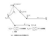
- FIG. 1 shows a schematic diagram of matching.
- the input coordinate value X n (t) and the model coordinate value X m (t) are as follows.
- the input coordinate value corresponds to the measurement overhead line data
- the model coordinate value corresponds to the reference overhead line data.
- k (t) represents a time deviation from the ideal corresponding point.
- “Time shift from ideal corresponding point” means that when the same trajectory (same speed, no measurement error, etc.) as the two models, the first point of the model point is necessarily the first input point The second corresponds to the second, and thereafter overlaps in the same manner. At this time, the corresponding points at the same time in the model time and the input operation time are called “ideal corresponding points”.
- S t is the sum of the evaluation values in all points.
- D t be the Euclidean distance of the corresponding point between the input point and the model point.
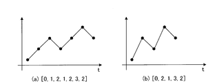
- the input data value is [0, 2, 1, 3, 2]
- the reference data value is [0, 1, 2, 1, 2, 3, 2] (FIG. 2). Performing these matchings is equivalent to calculating the shortest path in FIG.
- Dynamic programming is a method of shortening calculation time by storing calculation results and paths up to the middle when calculating this path.
- the path to the point (1,1) where the horizontal axis is 2 and the vertical axis is 1 is (0,0) ⁇ (1,1), (0,0) ⁇ (0,1) ⁇ (1,
- the continuous DP will be described with reference to FIG.
- the starting point and the ending point are determined, but in the case of continuous DP, it is not determined where the starting point is or where the ending point is.
- a free node whose distance to the next node is 0 is provided.
- the free node used to determine the start point is set to free node 1
- the free node used to determine the end point is set to free node 2.
- the matching between 5 points and 7 points is the same, but providing a free node has the same meaning as matching 3 points to 1 to 4 points.
- continuous DP Since the number of points to be matched changes in this way, continuous DP is referred to as expansion / contraction matching. Actually, the corresponding points can be “stretched” to 1 to 4 points.
- the evaluation formulas (1) and (2) are used for continuous DP. By using these equations, it is evaluated how far the measured overhead line data and the reference overhead line data are separated by the Euclidean distance.
- the object of the present invention is to extract the deviation of the overhead line in time series using image processing, and to compare the prepared reference overhead line deviation and the measured overhead line deviation using continuous DP matching. To provide a self-position estimation device capable of estimating the self-position of a train.
- “Extract time-series deviation of overhead lines using image processing” means that, for example, as described in Patent Document 4 and the like, the line sensor is installed on the train roof so as to look up vertically, The luminance signal for one line is photographed by scanning along the direction of the sleeper so as to cross the overhead line, and the difference in light and shade between the background and the overhead line in the image in which the luminance signal for the photographed one line is arranged in time series From this, the deviation of the overhead wire is acquired in time series.
- the present invention is characterized in that the self-position of the vehicle can be known when the overhead line deviation is obtained, and the deviation acquisition method is not limited to the method of Patent Document 4 using a line sensor.
- the train self-position estimation apparatus includes a reference deviation data input unit 10, a measurement deviation data input unit 20, a storage unit 30, a continuous DP matching unit 40, and a self-position estimation unit 50. And make up more.
- deviation information (reference deviation data) and absolute position information, which serve as a reference for the overhead line, which has been photographed and analyzed in advance for characteristic changes in the overhead line, are input and stored in the storage unit 30.
- the measurement deviation data input unit 20 the overhead line deviation information measured at the current position and the deviation information (measurement deviation data) up to several lines before are input and stored in the storage unit 30.
- the storage unit 30 stores deviation information including absolute deviation information, absolute position information, matching result information, and the like as a database.
- the continuous DP matching unit 40 performs expansion / contraction matching using the reference deviation data and the measurement deviation data, and calculates which position in the reference deviation data series most closely matches the measurement deviation data.
- the calculated continuous DP matching result (matching position data) is output to the storage unit 30 and stored.
- the above evaluation formulas (1) and (2) are used for expansion / contraction matching (continuous DP).
- the self-position estimation unit 50 estimates the self-position of the train using the continuous DP matching result obtained by the continuous DP matching unit 40 and the absolute position information.
- the absolute position information refers to information about “km” from the station.
- the continuous DP matching unit 40 only matches the measured deviation data (measured overhead line data) and the reference deviation data (reference overhead line data), and does not obtain absolute position information (km information). By this matching, only the information on what number of the reference overhead line data corresponds to the measurement overhead line data (more precisely, since multiple data are used, multiple correspondences between the measurement overhead line data point group and the reference overhead line data point group) is obtained. is there.
- the absolute position information is given to the self-position estimating unit 50 together with the reference overhead line data, and thereby the absolute position information (kilo-distance information) of the measured overhead line data is known.
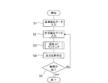
- deviation information (reference deviation data), which is a reference of the overhead wire taken and analyzed in advance, is input to the reference deviation data input unit 10 (step S1). Absolute position information is similarly input to the reference deviation data input unit 10.
- the deviation information of the overhead wire measured at the current position and the deviation information (measurement deviation data) up to several lines before are input to the measurement deviation data input unit 20 (step S2).
- the continuous DP matching unit 40 performs expansion / contraction matching to calculate which position in the reference deviation data series most closely matches the measurement deviation data (step). S3). Then, using the continuous DP matching result and the absolute position information by the continuous DP matching unit 40, the self position estimation unit 50 estimates the self position of the train (step S4). Further, steps S2 to S4 are repeated until photographing of the overhead line (overhead line measurement) is completed (step S5).
- the self-position of the train is known with high accuracy.
- the self-position of the train can be known frequently.
- Self-position estimation is possible even if the speed is different from that of the reference data.
- Stable self-position estimation is possible by using multiple deviation information.
- No GPS or encoder is required.
- GPS and encoders cannot detect even if they enter the up and down lines by mistake, but the present invention can detect these because the up and down lines have different deviations. .
- An object of the present invention is to extract the height of overhead lines in time series using image processing, and compare a reference overhead line height prepared in advance with a measured overhead line height using continuous DP matching. It is an object to provide a self-position estimation apparatus that can estimate the self-position.
- “Extracting the height of overhead lines in time series using image processing” means, for example, the height of overhead lines by triangulation using a plurality of line sensors installed so as to look up vertically above the train roof. It is to measure in time series. The difference from the first embodiment is that height information is used instead of overhead line deviation.
- the overhead line height is also different from the railway line, so it can be used for self-position estimation because it has a characteristic change.
- the train self-position estimation apparatus includes a reference height data input unit 11, a measured height data input unit 21, a storage unit 31, a continuous DP matching unit 41, and a self-position estimation unit 51. And make up more.
- the reference height data input unit 11 stores the height information (reference height data) and the absolute position information, which serve as a reference for the overhead line taken and analyzed in advance for characteristic changes of the overhead line, in the storage unit.
- the measured height data input unit 12 stores the height information of the overhead line measured at the current position and the height information (measured height data) up to several lines before that in the storage unit.
- the storage unit 31 stores, as a database, height information, absolute position information, matching result information, and the like made up of reference height data and measured height data.
- the continuous DP matching unit 41 performs expansion / contraction matching using the reference height data and the measured height data, and calculates which position in the reference height data series most closely matches the measured height data. Perform DP matching.
- the calculated continuous DP matching result (matching position data) is output to the storage unit 31 and stored.
- the self-position estimating unit 51 estimates the self-position of the train using the continuous DP matching result and the absolute position information.
- step T1 height information (reference height data) that serves as a reference for the overhead line imaged and analyzed in advance is input to the reference height data input unit 11 (step T1).
- the absolute position information is similarly input to the reference height data input unit 11.
- step T2 the height information of the overhead line measured at the current position and the height information (measured height data) up to several lines before are input to the measured height data input unit 21 (step T2).
- the continuous DP matching unit 41 performs expansion / contraction matching to calculate which position in the reference height data series most closely matches the measured height data (step). T3). Then, using the continuous DP matching result and the absolute position information by the continuous DP matching unit 41, the self position estimation unit 51 estimates the self position of the train (step T4). Further, steps T2 to T4 are repeated (step T5) until the photographing of the overhead line (measurement of the overhead line) is completed.
- the self-position of the train is known with high accuracy.
- the self-position of the train can be known frequently.
- Self-position estimation is possible even if the speed is different from that of the reference data.
- Stable self-position estimation is possible by using multiple height information.
- No GPS or encoder is required.
- the object of the present invention is to extract the wear width of the overhead line in time series using image processing, and to compare the prepared reference overhead line wear width and the measured overhead line wear width using continuous DP matching. To provide a self-position estimation device capable of estimating the self-position of a train.
- “Extracting the wear width of an overhead line in time series using image processing” means that, for example, as in the method of Patent Document 4, the overhead line is imaged in time series using a line sensor, and the wear width is measured. Is to do.
- the difference from Embodiments 1 and 2 is that wear width information is used instead of the displacement and height of the overhead wire.
- the overhead wire wear width is also different from the track, etc., so it can be used for self-position estimation because it has a characteristic change.
- the train self-position estimation apparatus includes a reference wear width data input unit 12, a measured wear width data input unit 22, a storage unit 32, a continuous DP matching unit 42, and a self-position estimation unit 52. And make up more.
- the reference wear width data input unit 12 inputs wear width information (reference wear width data) that serves as a reference for the overhead wire taken and analyzed in advance for characteristic changes in the overhead wire, and stores the absolute position information in the storage unit 32. .
- the wear width information of the overhead wire measured at the current position and the wear width information (measured wear width data) up to several lines before are input and stored in the storage unit 32.
- the storage unit 32 stores, as a database, wear width information, absolute position information, matching result information, and the like made up of reference wear width data and measured wear width data.
- the continuous DP matching unit 42 performs expansion / contraction matching using the reference wear width data and the measured wear width data, and calculates which position in the reference wear width data series most closely matches the measured wear width data series. Perform DP matching.
- the calculated continuous DP matching result (matching position data) is output to the storage unit 32 and stored.
- the self position estimating unit 52 estimates the self position of the train using the continuous DP matching result and the absolute position information.
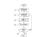
- wear width information (reference wear width data), which is a reference of the overhead wire taken and analyzed in advance, is input to the reference wear width data input unit 12 (step U1).
- the absolute position information is similarly input to the reference wear width data input unit 12.
- the wear width information of the overhead wire measured at the current position and the wear width information (measured wear width data) up to several lines from there are input to the measured wear width data input unit 22 (step U2).
- the continuous DP matching unit 42 performs expansion / contraction matching to calculate which position in the reference wear width data series most closely matches the measured wear width data (step). U3). Then, using the continuous DP matching result and the absolute position information by the continuous DP matching unit 42, the self position estimation unit 52 estimates the self position of the train (step U4). Further, steps U2 to U4 are repeated until photographing of the overhead line (measurement of the overhead line) is completed (step U5).
- the self-position of the train is known with high accuracy.
- the self-position of the train can be known frequently.
- Self-position estimation is possible even if the speed is different from that of the reference data.
- Stable self-position estimation is possible by using multiple wear width information.
- No GPS or encoder is required.
- the object of the present invention is to extract the deviation, height and wear width of the overhead line in time series using image processing, and use the continuous DP matching for the reference overhead line information and the measurement overhead line information prepared in advance. It is to provide a self-position estimation device that can estimate the self-position of a train by comparing.
- “Extracting the displacement, height, and wear width of overhead lines in time series using image processing” means, for example, using a plurality of line sensors installed on a train roof so as to look up vertically upward.
- the displacement, height, and wear width (collectively referred to as overhead line information) are measured in time series.
- the difference from Examples 1, 2, and 3 is that a plurality (two combinations or all three) of the deflection, height, and wear width of the overhead wire are used independently.
- the train self-position estimation apparatus includes a reference information data input unit 13, a measurement information data input unit 23, a storage unit 33, a continuous DP matching unit 43, and a self-position estimation unit 53.
- a reference information data input unit 13 information (reference overhead line data) and absolute position information that serve as a reference for overhead line information of the overhead line that has been photographed and analyzed in advance for characteristic changes of the overhead line are input and stored in the storage unit 33.
- the overhead line information of the overhead line measured at the current position and the overhead line information (measurement overhead line data) up to several lines before are input and stored in the storage unit 33.
- the storage unit 33 stores overhead line information, absolute position information, matching result information, and the like made up of reference overhead line data and measurement overhead line data as a database.
- the continuous DP matching unit 43 performs expansion / contraction matching using the reference overhead line data and the measurement overhead line data, and calculates which position in the reference information data series most closely matches the measurement information data, that is, performs continuous DP matching. .
- the calculated continuous DP matching result (matching position data) is output to the storage unit 33 and stored.
- the self-position estimating unit 53 estimates the self-position of the train using the continuous DP matching result and the absolute position information.
- the reference overhead line information (reference overhead line data) that has been photographed and analyzed in advance is input to the reference overhead line data input unit 13 (step V1).
- the absolute position information is similarly input to the reference overhead line data input unit 13.
- the overhead line information of the overhead line measured at the current position and the overhead line information (measurement overhead line data) up to several lines before are input to the measurement overhead line data input unit 23 (step V2).
- the continuous DP matching unit 43 performs expansion / contraction matching to calculate which position in the reference overhead line data series most closely matches the measurement overhead line data (step V3). Then, using the continuous DP matching result and the absolute position information by the continuous DP matching unit 43, the self position estimation unit 53 estimates the self position of the train (step V4). Further, steps V2 to V4 are repeated until the shooting of the overhead line (measurement of the overhead line) is completed (step V5).
- the self-position of the train is known with high accuracy.
- the self-position of the train can be known frequently.
- Self-position estimation is possible even if the speed is different from that of the reference data.
- Stable self-position estimation is possible by using multiple overhead line information.
- No GPS or encoder is required.
- GPS and encoder cannot detect even if they enter the up line and down line by mistake, but the present invention can detect these because the overhead line of up line and down line has different information. is there.
- Example 5 It is an object of the present invention to extract a deviation of an overhead line in a time series using a distance measuring sensor, and to compare a prepared reference overhead line deviation and a measured overhead line deviation using continuous DP matching. It is to provide a self-position estimation device that can estimate the self-position of a train. The difference from the first embodiment is that a distance measuring sensor is used instead of image processing to extract the deviation of the overhead line.
- a distance sensor is installed on the train roof so that it looks vertically upward, and the distance for one line is acquired in time series by measuring along the sleeper direction so as to cross the overhead line. In an image in which the distances for one line are arranged in time series, the distance to the overhead line is shorter than the background, so that the overhead line can be detected.
- the distance measuring sensor is a sensor that can acquire the distance and the direction thereof, and the deviation of the overhead wire can be acquired by using the information. Specifically, the deviation of the overhead wire can be acquired by using methods such as Patent Document 6 and Patent Document 7.
- the present invention is characterized in that the self-position of the vehicle is known when the overhead line deviation is obtained, and the deviation acquisition method is not limited to the method described in the above document using the distance measuring sensor.
- the train self-position estimation apparatus includes a reference deviation data input unit 10, a measurement deviation data input unit 20, a storage unit 30, a continuous DP matching unit 40, a self-position estimation, as shown in FIG.
- the part 50 comprises.
- deviation information reference deviation data
- absolute position information which serve as a reference for the overhead line, which has been photographed and analyzed in advance for characteristic changes in the overhead line, are input and stored in the storage unit 30. .
- the overhead line deviation information measured at the current position and the deviation information (measurement deviation data) up to several lines before are input and stored in the storage unit 30.
- the storage unit 30 stores deviation information including absolute deviation information, absolute position information, matching result information, and the like as a database.
- the continuous DP matching unit 40 performs expansion / contraction matching using the reference deviation data and the measurement deviation data, and calculates which position in the reference deviation data series most closely matches the measurement deviation data. Perform DP matching.
- the calculated continuous DP matching result (matching position data) is output to the storage unit 30 and stored.
- the self-position estimating unit 50 estimates the self-position of the train using the continuous DP matching result and the absolute position information.
- deviation information (reference deviation data), which is a reference of the overhead wire taken and analyzed in advance, is input to the reference deviation data input unit 10 (step S1). Absolute position information is similarly input to the reference deviation data input unit 10.
- the deviation information of the overhead wire measured at the current position and the deviation information (measurement deviation data) up to several lines before are input to the measurement deviation data input unit 20 (step S2).
- the continuous DP matching unit 40 performs expansion / contraction matching to calculate which position in the reference deviation data series most closely matches the measurement deviation data (step). S3). Then, using the continuous DP matching result and the absolute position information by the continuous DP matching unit 40, the self position estimation unit 50 estimates the self position of the train (step S4). Further, steps S2 to S4 are repeated until photographing of the overhead line (overhead line measurement) is completed (step S5).
- the self-position of the train is known with high accuracy.
- the self-position of the train can be known frequently.
- Self-position estimation is possible even if the speed is different from the reference data acquisition time.
- Stable self-position estimation is possible by using multiple deviation information.
- No GPS or encoder is required.
- GPS and encoders cannot detect even if they enter the up and down lines by mistake, but the present invention can detect these because the up and down lines have different deviations. .
- the object of the present invention is to extract the height of the overhead line in time series using a distance measuring sensor, and compare the prepared reference overhead line height and the measured overhead line height using continuous DP matching.
- the difference from the fifth embodiment is that height information is used instead of overhead line deviation.
- the overhead line height is also different from the railway line, so it can be used for self-position estimation because it has a characteristic change.
- the train self-position estimation apparatus includes a quasi-height data input unit 11, a measured height data input unit 21, a storage unit 31, a continuous DP matching unit 41, and a self-position estimation.
- the unit 51 is configured.
- the height information (reference height data) and the absolute position information serving as a reference for the overhead line taken and analyzed in advance for characteristic changes in the overhead line are input and stored in the storage unit 31. .
- the height information of the overhead line measured at the current position and the height information (measured height data) up to several lines before are input and stored in the storage unit 31.
- the storage unit 31 stores, as a database, height information, absolute position information, matching result information, and the like made up of reference height data and measured height data.
- the continuous DP matching unit 41 performs expansion / contraction matching using the reference height data and the measured height data, and calculates which position in the reference height data series most closely matches the measured height data. Perform DP matching.
- the calculated continuous DP matching result (matching position data) is output to the storage unit 31 and stored.
- the self-position estimating unit 51 estimates the self-position of the train using the continuous DP matching result and the absolute position information.
- step T1 height information (reference height data) that serves as a reference for the overhead line imaged and analyzed in advance is input to the reference height data input unit 11 (step T1).
- the absolute position information is similarly input to the reference height data input unit 11.
- step T2 the height information of the overhead line measured at the current position and the height information (measured height data) up to several lines before are input to the measured height data input unit 21 (step T2).
- the continuous DP matching unit 41 performs expansion / contraction matching to calculate which position in the reference height data series most closely matches the measured height data (step). T3). Then, using the continuous DP matching result and the absolute position information by the continuous DP matching unit 41, the self position estimation unit 51 estimates the self position of the train (step T4). Further, steps T2 to T4 are repeated (step T5) until the photographing of the overhead line (measurement of the overhead line) is completed.
- the following effects can be obtained.
- (1) The self-position of the train is known with high accuracy.
- (2) The self-position of the train can be known frequently.
- (3) Self-position estimation is possible even if the speed is different from the reference data acquisition time.
- (4) Stable self-position estimation is possible by using multiple height information.
- No GPS or encoder is required.
- An object of the present invention is to extract deviations and heights (collectively referred to as overhead line information) using a distance measuring sensor, and use continuous DP matching between previously prepared reference overhead line information and measured overhead line information. It is an object to provide a self-position estimation device that can estimate the self-position of a train by comparing the above.
- the difference from Examples 5 and 6 is that the deflection and height of the overhead wire are not independent, but a plurality of uses, that is, the deflection and height of the overhead wire are used together. By using a plurality of pieces of information together, it is considered that the self-position estimation accuracy is improved as compared with the case where only one piece of information is used.
- the train self-position estimation apparatus includes a reference information data input unit 13, a measurement information data input unit 23, a storage unit 33, a continuous DP matching unit 43, and a self-position estimation unit 53, as shown in FIG. And make up more.
- the reference information data input unit 13 inputs the reference overhead line information (reference overhead line data) and the absolute position information, which are taken and analyzed in advance for characteristic changes of the overhead line, and stores them in the storage unit 33.
- the overhead line information of the overhead line measured at the current position and the overhead line information (measurement overhead line data) up to several lines before are input and stored in the storage unit 33.
- the storage unit 33 stores overhead line information, absolute position information, matching result information, and the like made up of reference overhead line data and measurement overhead line data as a database.
- the continuous DP matching unit 43 performs expansion / contraction matching using the reference information data and the measurement information data, and calculates which position in the reference information data series most closely matches the measurement information data, that is, performs continuous DP matching. .
- the calculated continuous DP matching result (matching position data) is output to the storage unit 33 and stored.
- the self-position estimating unit 53 estimates the self-position of the train using the continuous DP matching result and the absolute position information.
- the flowchart of this embodiment is the same as that of the fourth embodiment shown in FIG.
- the reference overhead line information reference overhead line data
- the absolute position information is similarly input to the reference overhead line data input unit 13.
- the overhead line information of the overhead line measured at the current position and the overhead line information (measurement overhead line data) up to several lines before are input to the measurement overhead line data input unit 23 (step V2).
- the continuous DP matching unit 43 performs expansion / contraction matching to calculate which position in the reference overhead line data series most closely matches the measurement overhead line data (step V3). Then, using the continuous DP matching result and the absolute position information by the continuous DP matching unit 43, the self position estimation unit 53 estimates the self position of the train (step V4). Further, steps V2 to V4 are repeated until the shooting of the overhead line (measurement of the overhead line) is completed (step V5).
- the following effects can be obtained.
- (1) The self-position of the train is known with high accuracy.
- (2) The self-position of the train can be known frequently.
- (3) Self-position estimation is possible even if the speed is different from the reference data acquisition time.
- Stable self-position estimation is possible by using multiple overhead line information.
- No GPS or encoder is required.
- (6) GPS and encoder cannot detect even if they enter the up line and down line by mistake, but the present invention can detect these because the overhead line of up line and down line has different information. is there.
- the present invention can be widely used industrially as a train self-position estimation device by continuous DP matching.
Landscapes
- Engineering & Computer Science (AREA)
- Mechanical Engineering (AREA)
- Computer Vision & Pattern Recognition (AREA)
- Physics & Mathematics (AREA)
- General Physics & Mathematics (AREA)
- Theoretical Computer Science (AREA)
- Train Traffic Observation, Control, And Security (AREA)
- Image Analysis (AREA)
- Electric Propulsion And Braking For Vehicles (AREA)
- Navigation (AREA)
Priority Applications (2)
| Application Number | Priority Date | Filing Date | Title |
|---|---|---|---|
| CN201480061600.7A CN105722742B (zh) | 2013-11-11 | 2014-11-07 | 电车的自身位置推测装置 |
| EP14860982.9A EP3069955A4 (en) | 2013-11-11 | 2014-11-07 | Train self-position estimation device |
Applications Claiming Priority (2)
| Application Number | Priority Date | Filing Date | Title |
|---|---|---|---|
| JP2013232760A JP6225362B2 (ja) | 2013-11-11 | 2013-11-11 | 電車の自己位置推定装置 |
| JP2013-232760 | 2013-11-11 |
Publications (1)
| Publication Number | Publication Date |
|---|---|
| WO2015068788A1 true WO2015068788A1 (ja) | 2015-05-14 |
Family
ID=53041563
Family Applications (1)
| Application Number | Title | Priority Date | Filing Date |
|---|---|---|---|
| PCT/JP2014/079526 Ceased WO2015068788A1 (ja) | 2013-11-11 | 2014-11-07 | 電車の自己位置推定装置 |
Country Status (4)
| Country | Link |
|---|---|
| EP (1) | EP3069955A4 (https=) |
| JP (1) | JP6225362B2 (https=) |
| CN (1) | CN105722742B (https=) |
| WO (1) | WO2015068788A1 (https=) |
Families Citing this family (6)
| Publication number | Priority date | Publication date | Assignee | Title |
|---|---|---|---|---|
| JP6583916B2 (ja) * | 2015-11-17 | 2019-10-02 | 日本電気株式会社 | トロリ線の摩耗分析装置、摩耗分析方法、およびプログラム |
| EP3431362B1 (de) * | 2017-06-30 | 2025-05-28 | Deutsches Zentrum für Luft- und Raumfahrt e.V. | Verfahren zur infrastrukturlosen detektion einer überfahrt eines gleisabschnitts durch ein schienenfahrzeug |
| CN107585181A (zh) * | 2017-08-11 | 2018-01-16 | 北京交通大学 | 一种基于深度学习的列车定位系统 |
| JP6986936B2 (ja) | 2017-11-21 | 2021-12-22 | 株式会社日立製作所 | 車両制御システム |
| CN109398422A (zh) * | 2018-10-25 | 2019-03-01 | 中车株洲电力机车有限公司 | 一种停车时车辆位置确定方法及对标停车方法 |
| JP7555072B2 (ja) * | 2020-12-16 | 2024-09-24 | 株式会社豊田自動織機 | 自己位置推定装置、及び移動体 |
Citations (12)
| Publication number | Priority date | Publication date | Assignee | Title |
|---|---|---|---|---|
| JP2000085581A (ja) * | 1998-09-18 | 2000-03-28 | Nippon Signal Co Ltd:The | 列車運行情報抽出装置 |
| JP2002037070A (ja) | 2000-07-24 | 2002-02-06 | Mitsubishi Electric Corp | 車両位置検出装置および車両速度検出装置 |
| JP2008247154A (ja) | 2007-03-30 | 2008-10-16 | Kyosan Electric Mfg Co Ltd | 列車位置検知装置と列車制御装置 |
| JP2008298733A (ja) | 2007-06-04 | 2008-12-11 | Meidensha Corp | 画像処理によるトロリ線摩耗測定装置 |
| JP2009234338A (ja) * | 2008-03-26 | 2009-10-15 | Railway Technical Res Inst | 鉄道のトロリ線の状態診断装置 |
| JP2010243416A (ja) | 2009-04-09 | 2010-10-28 | Meidensha Corp | トロリ線検測装置及び検測方法 |
| JP2010243417A (ja) | 2009-04-09 | 2010-10-28 | Meidensha Corp | トロリ線検測装置 |
| JP2010285054A (ja) * | 2009-06-11 | 2010-12-24 | Meidensha Corp | 電気鉄道保守用車両位置測定装置 |
| JP2011201426A (ja) | 2010-03-25 | 2011-10-13 | National Traffic Safety & Environment Laboratory | 列車搭載用画像処理システム |
| JP2011209026A (ja) | 2010-03-29 | 2011-10-20 | Mitsubishi Electric Corp | 列車速度計測システム |
| JP2011230722A (ja) * | 2010-04-30 | 2011-11-17 | Meidensha Corp | 電気鉄道保守用車両位置測定装置 |
| JP2012191778A (ja) * | 2011-03-11 | 2012-10-04 | Railway Technical Research Institute | パンタグラフの動特性の異常検出方法 |
Family Cites Families (6)
| Publication number | Priority date | Publication date | Assignee | Title |
|---|---|---|---|---|
| DE2814348C3 (de) * | 1978-04-03 | 1986-02-13 | Siemens AG, 1000 Berlin und 8000 München | Orientierungseinrichtung für ein spurgebundenes Fahrzeug |
| DE19532104C1 (de) * | 1995-08-30 | 1997-01-16 | Daimler Benz Ag | Verfahren und Vorrichtung zur Bestimmung der Position wenigstens einer Stelle eines spurgeführten Fahrzeugs |
| DE19940350C2 (de) * | 1999-08-25 | 2003-06-05 | Deutsche Bahn Ag | Verfahren und Anordnung zur Überwachung des Fahrdrahtes einer Fahrtstrecke für elektrisch antreibbare Schienenfahrzeuge |
| DE102007028325B4 (de) * | 2007-06-15 | 2012-09-06 | Deutsches Zentrum für Luft- und Raumfahrt e.V. | Ortungsvorrichtung zur Ermittlung der Position von fahrweggebundenen Fahrzeugen |
| DE102007049248B4 (de) * | 2007-10-12 | 2013-07-04 | Deutsches Zentrum für Luft- und Raumfahrt e.V. | Verfahren zur Positionsbestimmung eines Schienenfahrzeugs |
| NL2004944C2 (nl) * | 2010-06-22 | 2011-12-27 | Ronald Johannes Bakker | Systeem voor het lokaliseren van objecten op een spoorbaan, en werkwijze daarvoor. |
-
2013
- 2013-11-11 JP JP2013232760A patent/JP6225362B2/ja active Active
-
2014
- 2014-11-07 WO PCT/JP2014/079526 patent/WO2015068788A1/ja not_active Ceased
- 2014-11-07 EP EP14860982.9A patent/EP3069955A4/en not_active Withdrawn
- 2014-11-07 CN CN201480061600.7A patent/CN105722742B/zh active Active
Patent Citations (12)
| Publication number | Priority date | Publication date | Assignee | Title |
|---|---|---|---|---|
| JP2000085581A (ja) * | 1998-09-18 | 2000-03-28 | Nippon Signal Co Ltd:The | 列車運行情報抽出装置 |
| JP2002037070A (ja) | 2000-07-24 | 2002-02-06 | Mitsubishi Electric Corp | 車両位置検出装置および車両速度検出装置 |
| JP2008247154A (ja) | 2007-03-30 | 2008-10-16 | Kyosan Electric Mfg Co Ltd | 列車位置検知装置と列車制御装置 |
| JP2008298733A (ja) | 2007-06-04 | 2008-12-11 | Meidensha Corp | 画像処理によるトロリ線摩耗測定装置 |
| JP2009234338A (ja) * | 2008-03-26 | 2009-10-15 | Railway Technical Res Inst | 鉄道のトロリ線の状態診断装置 |
| JP2010243416A (ja) | 2009-04-09 | 2010-10-28 | Meidensha Corp | トロリ線検測装置及び検測方法 |
| JP2010243417A (ja) | 2009-04-09 | 2010-10-28 | Meidensha Corp | トロリ線検測装置 |
| JP2010285054A (ja) * | 2009-06-11 | 2010-12-24 | Meidensha Corp | 電気鉄道保守用車両位置測定装置 |
| JP2011201426A (ja) | 2010-03-25 | 2011-10-13 | National Traffic Safety & Environment Laboratory | 列車搭載用画像処理システム |
| JP2011209026A (ja) | 2010-03-29 | 2011-10-20 | Mitsubishi Electric Corp | 列車速度計測システム |
| JP2011230722A (ja) * | 2010-04-30 | 2011-11-17 | Meidensha Corp | 電気鉄道保守用車両位置測定装置 |
| JP2012191778A (ja) * | 2011-03-11 | 2012-10-04 | Railway Technical Research Institute | パンタグラフの動特性の異常検出方法 |
Non-Patent Citations (2)
| Title |
|---|
| See also references of EP3069955A4 * |
| SEIICHI UCHIDA: "DP Matching - Fundamentals and Applications", IEICE TECHNICAL REPORT, PRMU, vol. 166, 2006, pages 31 - 36 |
Also Published As
| Publication number | Publication date |
|---|---|
| JP2015093532A (ja) | 2015-05-18 |
| JP6225362B2 (ja) | 2017-11-08 |
| EP3069955A1 (en) | 2016-09-21 |
| CN105722742B (zh) | 2018-09-25 |
| CN105722742A (zh) | 2016-06-29 |
| EP3069955A4 (en) | 2017-06-28 |
Similar Documents
| Publication | Publication Date | Title |
|---|---|---|
| JP6225362B2 (ja) | 電車の自己位置推定装置 | |
| CN102203552B (zh) | 视差计算方法和视差计算装置 | |
| CN108778889B (zh) | 用于检测轨道旁的固定点的方法和测量系统 | |
| JP4363295B2 (ja) | ステレオ画像による平面推定方法 | |
| JP5861318B2 (ja) | トロリ線データ比較装置 | |
| JP5494286B2 (ja) | 架線位置測定装置 | |
| EP2264403A3 (en) | Positioning device and positioning method | |
| US20200108849A1 (en) | Running location identification system, running location identification apparatus, and running location identification method for railroad cars | |
| KR20190097326A (ko) | 신호기 인식 장치 및 신호기 인식 방법 | |
| US10133940B2 (en) | Road surface undulation estimation device and road surface undulation estimation method | |
| KR102255978B1 (ko) | 3d 센서를 활용한 객체 인식 기반 고해상도 철도 터널 내부 정밀 지도 생성 장치 및 방법 | |
| US9815480B2 (en) | Method and device for monitoring the function of a driver assistance system | |
| JP5151845B2 (ja) | 画像処理によるパンタグラフの鉛直加速度測定装置および測定方法 | |
| JP6699323B2 (ja) | 電車設備の三次元計測装置及び三次元計測方法 | |
| JP2017010393A (ja) | 地図生成装置及びプログラム | |
| CN114830180B (zh) | 摄像机自动检查系统 | |
| JP2015093532A5 (https=) | ||
| JP6638353B2 (ja) | 重錘位置検出装置及び方法 | |
| CN115235510B (zh) | 一种适用于隧道的行驶工具的里程校准方法、系统及终端 | |
| JP5936527B2 (ja) | 画像処理装置および画像処理方法 | |
| CN119492370A (zh) | 基于单程轨迹校正的高精度铁路地图生成方法和系统 | |
| JP7127607B2 (ja) | レール曲率推定装置 | |
| KR101555823B1 (ko) | 로봇 제어 방법 및 장치 | |
| KR20210067383A (ko) | 이동 로봇의 위치 추정 시스템 및 방법 | |
| JP2020006845A (ja) | 線路曲率推定装置及び方法 |
Legal Events
| Date | Code | Title | Description |
|---|---|---|---|
| 121 | Ep: the epo has been informed by wipo that ep was designated in this application |
Ref document number: 14860982 Country of ref document: EP Kind code of ref document: A1 |
|
| REEP | Request for entry into the european phase |
Ref document number: 2014860982 Country of ref document: EP |
|
| WWE | Wipo information: entry into national phase |
Ref document number: 2014860982 Country of ref document: EP |
|
| NENP | Non-entry into the national phase |
Ref country code: DE |