WO2015068754A1 - 電動圧縮機の取付構造 - Google Patents
電動圧縮機の取付構造 Download PDFInfo
- Publication number
- WO2015068754A1 WO2015068754A1 PCT/JP2014/079404 JP2014079404W WO2015068754A1 WO 2015068754 A1 WO2015068754 A1 WO 2015068754A1 JP 2014079404 W JP2014079404 W JP 2014079404W WO 2015068754 A1 WO2015068754 A1 WO 2015068754A1
- Authority
- WO
- WIPO (PCT)
- Prior art keywords
- electric compressor
- compressor
- electric
- vehicle
- elastic members
- Prior art date
- Legal status (The legal status is an assumption and is not a legal conclusion. Google has not performed a legal analysis and makes no representation as to the accuracy of the status listed.)
- Ceased
Links
Images






Classifications
-
- F—MECHANICAL ENGINEERING; LIGHTING; HEATING; WEAPONS; BLASTING
- F04—POSITIVE - DISPLACEMENT MACHINES FOR LIQUIDS; PUMPS FOR LIQUIDS OR ELASTIC FLUIDS
- F04B—POSITIVE-DISPLACEMENT MACHINES FOR LIQUIDS; PUMPS
- F04B39/00—Component parts, details, or accessories, of pumps or pumping systems specially adapted for elastic fluids, not otherwise provided for in, or of interest apart from, groups F04B25/00 - F04B37/00
- F04B39/0027—Pulsation and noise damping means
- F04B39/0044—Pulsation and noise damping means with vibration damping supports
-
- F—MECHANICAL ENGINEERING; LIGHTING; HEATING; WEAPONS; BLASTING
- F01—MACHINES OR ENGINES IN GENERAL; ENGINE PLANTS IN GENERAL; STEAM ENGINES
- F01C—ROTARY-PISTON OR OSCILLATING-PISTON MACHINES OR ENGINES
- F01C21/00—Component parts, details or accessories not provided for in groups F01C1/00 - F01C20/00
- F01C21/007—General arrangements of parts; Frames and supporting elements
-
- F—MECHANICAL ENGINEERING; LIGHTING; HEATING; WEAPONS; BLASTING
- F04—POSITIVE - DISPLACEMENT MACHINES FOR LIQUIDS; PUMPS FOR LIQUIDS OR ELASTIC FLUIDS
- F04B—POSITIVE-DISPLACEMENT MACHINES FOR LIQUIDS; PUMPS
- F04B39/00—Component parts, details, or accessories, of pumps or pumping systems specially adapted for elastic fluids, not otherwise provided for in, or of interest apart from, groups F04B25/00 - F04B37/00
-
- F—MECHANICAL ENGINEERING; LIGHTING; HEATING; WEAPONS; BLASTING
- F04—POSITIVE - DISPLACEMENT MACHINES FOR LIQUIDS; PUMPS FOR LIQUIDS OR ELASTIC FLUIDS
- F04B—POSITIVE-DISPLACEMENT MACHINES FOR LIQUIDS; PUMPS
- F04B53/00—Component parts, details or accessories not provided for in, or of interest apart from, groups F04B1/00 - F04B23/00 or F04B39/00 - F04B47/00
- F04B53/001—Noise damping
- F04B53/003—Noise damping by damping supports
-
- F—MECHANICAL ENGINEERING; LIGHTING; HEATING; WEAPONS; BLASTING
- F04—POSITIVE - DISPLACEMENT MACHINES FOR LIQUIDS; PUMPS FOR LIQUIDS OR ELASTIC FLUIDS
- F04C—ROTARY-PISTON, OR OSCILLATING-PISTON, POSITIVE-DISPLACEMENT MACHINES FOR LIQUIDS; ROTARY-PISTON, OR OSCILLATING-PISTON, POSITIVE-DISPLACEMENT PUMPS
- F04C23/00—Combinations of two or more pumps, each being of rotary-piston or oscillating-piston type, specially adapted for elastic fluids; Pumping installations specially adapted for elastic fluids; Multi-stage pumps specially adapted for elastic fluids
- F04C23/008—Hermetic pumps
-
- F—MECHANICAL ENGINEERING; LIGHTING; HEATING; WEAPONS; BLASTING
- F16—ENGINEERING ELEMENTS AND UNITS; GENERAL MEASURES FOR PRODUCING AND MAINTAINING EFFECTIVE FUNCTIONING OF MACHINES OR INSTALLATIONS; THERMAL INSULATION IN GENERAL
- F16F—SPRINGS; SHOCK-ABSORBERS; MEANS FOR DAMPING VIBRATION
- F16F15/00—Suppression of vibrations in systems; Means or arrangements for avoiding or reducing out-of-balance forces, e.g. due to motion
- F16F15/02—Suppression of vibrations of non-rotating, e.g. reciprocating systems; Suppression of vibrations of rotating systems by use of members not moving with the rotating systems
- F16F15/04—Suppression of vibrations of non-rotating, e.g. reciprocating systems; Suppression of vibrations of rotating systems by use of members not moving with the rotating systems using elastic means
- F16F15/08—Suppression of vibrations of non-rotating, e.g. reciprocating systems; Suppression of vibrations of rotating systems by use of members not moving with the rotating systems using elastic means with rubber springs ; with springs made of rubber and metal
-
- F—MECHANICAL ENGINEERING; LIGHTING; HEATING; WEAPONS; BLASTING
- F04—POSITIVE - DISPLACEMENT MACHINES FOR LIQUIDS; PUMPS FOR LIQUIDS OR ELASTIC FLUIDS
- F04C—ROTARY-PISTON, OR OSCILLATING-PISTON, POSITIVE-DISPLACEMENT MACHINES FOR LIQUIDS; ROTARY-PISTON, OR OSCILLATING-PISTON, POSITIVE-DISPLACEMENT PUMPS
- F04C18/00—Rotary-piston pumps specially adapted for elastic fluids
- F04C18/02—Rotary-piston pumps specially adapted for elastic fluids of arcuate-engagement type, i.e. with circular translatory movement of co-operating members, each member having the same number of teeth or tooth-equivalents
- F04C18/0207—Rotary-piston pumps specially adapted for elastic fluids of arcuate-engagement type, i.e. with circular translatory movement of co-operating members, each member having the same number of teeth or tooth-equivalents both members having co-operating elements in spiral form
- F04C18/0215—Rotary-piston pumps specially adapted for elastic fluids of arcuate-engagement type, i.e. with circular translatory movement of co-operating members, each member having the same number of teeth or tooth-equivalents both members having co-operating elements in spiral form where only one member is moving
-
- F—MECHANICAL ENGINEERING; LIGHTING; HEATING; WEAPONS; BLASTING
- F04—POSITIVE - DISPLACEMENT MACHINES FOR LIQUIDS; PUMPS FOR LIQUIDS OR ELASTIC FLUIDS
- F04C—ROTARY-PISTON, OR OSCILLATING-PISTON, POSITIVE-DISPLACEMENT MACHINES FOR LIQUIDS; ROTARY-PISTON, OR OSCILLATING-PISTON, POSITIVE-DISPLACEMENT PUMPS
- F04C2270/00—Control; Monitoring or safety arrangements
- F04C2270/12—Vibration
Definitions
- the present invention relates to an electric motor, a compression mechanism driven by the electric motor, and a structure for mounting the electric compressor integrated with an inverter for driving the electric motor to the vehicle.
- An electric compressor used in a vehicle air conditioner is attached to a vehicle via, for example, a rubber elastic support member, and usually four elastic support members are used.
- the resonance frequency of the elastic support member that supports the compression mechanism side of the electric compressor and the resonance frequency of the elastic support member that supports the electric motor side of the electric compressor are set as appropriate, whereby the vibration of the electric compressor is set.
- a postoperative technique that suppresses the transmission of noise to the vehicle and the transmission of vehicle vibration to the electric compressor (see Patent Document 1, etc.).
- An object of the present invention is to provide an electric compressor mounting structure that can effectively suppress vibration transmission from an electric compressor to a vehicle while having a relatively simple configuration.
- the mounting structure of the electric compressor in which the electric motor, the compression mechanism driven by the electric motor, and the inverter that drives the electric motor are integrated, is fixed to the vehicle.
- a support member that elastically supports the electric compressor by three elastic members, two of the three elastic members being arranged on the electric motor side with respect to the center of gravity of the electric compressor, The remaining one is disposed closer to the compression mechanism than the position of the center of gravity.
- the electric compressor is elastically supported by the two elastic members arranged on the electric motor side with respect to the center of gravity position of the electric compressor and the one elastic member arranged on the compression mechanism side.
- FIG. 1 shows a main configuration of an electric compressor mounting structure according to an embodiment of the present invention.
- Fig.1 (a) is a principal part front view of the attachment structure of an electric compressor
- FIG.1 (b) is a principal part perspective view of the attachment structure of an electric compressor.
- the electric compressor mounting structure is for mounting the electric compressor 10 used in the vehicle air conditioner to a vehicle such as an electric vehicle or a hybrid vehicle.
- a support bracket 20 that is fixed to the body (not shown) and elastically supports the electric compressor 10 is included. That is, the electric compressor 10 is attached and fixed to the vehicle via the support bracket 20.
- the electric compressor 10 has a housing 11, in which an electric motor 12, a compression mechanism 13 driven by the electric motor 12, and an inverter 14 for driving the electric motor 12 are accommodated. (See FIG. 1 (a)). That is, the electric compressor 10 is configured as a so-called inverter-integrated electric compressor.
- the electric motor 12 and the compression mechanism 13 are arranged in series, and the output shaft 12 a of the electric motor 12 is directly connected to a drive shaft (not shown) of the compression mechanism 13.
- the electric motor 12 is, for example, a DC brushless motor
- the compression mechanism 13 is, for example, a scroll type compression mechanism configured by a fixed fixed scroll and a movable scroll.
- the inverter 14 is arranged on one end side (left side in the figure) in the housing 11.
- the present invention is not limited to this, and the arrangement of the inverter 14 can be arbitrarily set.
- the housing 11 is formed with a suction port 15 and a discharge port 16 to which a refrigerant pipe (not shown) of the vehicle air conditioner is connected.
- the suction port 15 opens above the electric motor 12, and the discharge port 16 opens at the upper end on the other end side (right side) opposite to the inverter 14.
- the electric motor 12 When the electric motor 12 is driven by the inverter 14, the electric motor 12 drives the compression mechanism 4 (the movable scroll) via the output shaft 12a.
- the electric compressor 10 sucks and compresses the refrigerant (low pressure refrigerant) of the vehicle air conditioner from the suction port 15 and discharges the compressed refrigerant (high pressure refrigerant) from the discharge port 16.
- the support bracket 20 is disposed between the electric compressor 10 and the body of the vehicle, in other words, below the electric compressor 10 and elastically supports the electric compressor 10.
- FIG. 2 shows the configuration of the support bracket 20.
- FIG. 2A is a plan view of the support bracket 20, and
- FIG. 2B is a perspective view of the support bracket 20.
- the support bracket 20 includes a compressor side bracket 21, a vehicle side bracket 22, and three elastic members 23 disposed between the compressor side bracket 21 and the vehicle side bracket 22. (23a to 23c).
- the compressor side bracket 21 is fixed to the lower part of the electric compressor 10 by bolts 31 and nuts 32.
- the vehicle side bracket 22 is fixed to the vehicle body by fastening means such as a bolt (not shown).
- the elastic member 23 is a rubber member, for example.
- the compressor side bracket 21 and the vehicle side bracket 22 are integrated with three elastic members 23 interposed therebetween. That is, the support bracket 20 is configured to be fixed to the vehicle and to elastically support the electric compressor 10 by the three elastic members 23 (so as to be elastically supported at three points). Accordingly, in the present embodiment, the support bracket 20 corresponds to the “support member” of the present invention, the compressor side bracket 21 corresponds to the “compressor side support member” of the present invention, and the vehicle side bracket 22 corresponds to the present invention. It corresponds to a “vehicle-side support member”.
- the compressor side bracket 21 and the vehicle side bracket 22 are formed using a stamped sheet metal member.
- the compressor side bracket 21 has elastic member attaching portions 21a to 21c formed by bending upward three tongue pieces protruding from the periphery of the flat surface.
- the vehicle-side bracket 22 is formed by bending upwards three tongue pieces protruding from the periphery of the flat surface so as to correspond to the elastic member mounting portions 21a to 21c of the compressor side bracket 21. 22a to 22c. Through holes are formed in the elastic member attaching portions 21a to 21c and 22a to 22c, respectively.
- a so-called double-bolt type round anti-vibration rubber (cylindrical anti-vibration rubber) is used as the elastic member 23 (23a to 23c).
- the elastic members 23 a to 23 c are disposed between the elastic member mounting portions 21 a to 21 c of the compressor side bracket 21 and the elastic member mounting portions 22 a to 22 c of the vehicle side bracket 22. Then, one bolt part of each elastic member 23a to 23c is inserted into the through hole of each elastic member attaching part 21a to 21c of the compressor side bracket 21, and the other bolt part is attached to each elastic member attaching part of the vehicle side bracket 22. These are integrated by inserting through the through holes of the portions 22a to 22c, and then screwing the nuts 33 to the respective bolt portions and tightening them.
- the present invention is not limited to this, and the compressor side bracket 21 and the vehicle side bracket 22 may be integrated through three elastic members 23 to form the support bracket 20. Further, an anti-vibration spring or an anti-vibration pad may be used as the elastic member 23.
- FIG. 3 is a front view of the main part of the mounting structure of the electric compressor (corresponding to FIG. 1A), and FIG. 4 is a side view of the main part of the mounting structure of the electric compressor.
- FIG. 5 is a plan view of the support bracket 20 (corresponding to FIG. 2A), and FIG. 6 is a view as viewed in A of FIG.
- two elastic members 23a and 23b among the three elastic members 23a to 23c are arranged closer to the electric motor 12 than the gravity center position G of the electric compressor 10.
- the remaining one elastic member 23 c is arranged closer to the compression mechanism 13 than the center of gravity G of the electric compressor 10.
- the three elastic members 23 when viewed from above the electric compressor 10 (that is, in plan view), the three elastic members 23 (23 a to 23 c) are provided on the electric compressor 10. Located on the outside.
- the two elastic members 23a and 23b arranged on the electric motor 12 side of the center of gravity position G of the electric compressor 10 are electrically compressed with the electric compressor 10 (the axis of the output shaft 12a of the electric motor 12) sandwiched therebetween.
- One elastic member 23c that is located on both the front and rear sides of the compressor 10 and is located closer to the compression mechanism 13 than the center of gravity G of the electric compressor 10 is outside the end surface of the electric compressor 10 on the compression mechanism 13 side. Located on the right side.
- one elastic member 23c arranged on the compression mechanism 13 side is located below a horizontal line H that passes through the center of gravity position G and extends in the left-right direction (longitudinal direction) of the electric compressor 10.
- the two elastic members 23 a and 23 b arranged on the motor 12 side are positioned symmetrically in the front-rear direction of the electric compressor 10 with the horizontal line H in between.
- the distance from the center of gravity position G to the support position (support point) of the compressor side bracket 21 by the elastic members 23a and 23b on the electric motor 12 side is L1, and the center of gravity position.
- the load distribution to the elastic members 23a to 23c when the electric compressor 10 is supported can be substantially equalized, and an appropriate vibration-proofing effect can be obtained and the elastic members 223a to 23c Durability will also be improved.
- the left-right direction (longitudinal direction) of the electric compressor 10 corresponds to the axial direction of the output shaft 12a of the electric motor 12, and the front-rear direction of the electric compressor 10 is the output shaft 12a of the electric motor 12. This corresponds to the horizontal direction orthogonal to the axial direction.
- the elastic member attaching portions 21a to 21c of the compressor side bracket 21 and the elastic member attaching portions 22a to 22c of the vehicle side bracket 22 are inclined at a predetermined angle with respect to the horizontal plane.
- the elastic member mounting portions 21c and 22c located closer to the compression mechanism 13 than the gravity center position G of the electric compressor 10 are inclined at an angle ⁇ with respect to the horizontal plane (see FIG. 3).
- the elastic member mounting portions 21a, 21b, 22a, and 22b located on the electric motor 12 side with respect to the gravity center position G of the machine 10 are inclined at an angle ⁇ with respect to the horizontal plane (see FIG. 6). Therefore, the elastic members 23a to 23c are arranged between the compressor side bracket 21 and the vehicle side bracket 22 so that the upper part thereof is inclined so as to be closer to the electric compressor 10 than the lower part. Yes.
- the elastic members 23a to 23c are arranged so as to be inclined in this way, the natural frequency of the entire support bracket 20 can be lowered without changing the spring constant (rubber hardness) of the elastic members 23a to 23c. Thereby, the vibration isolation area
- the elastic member mounting portions 21a to 21c of the compressor side bracket 21 and the elastic member mounting portions 22a to 22c of the vehicle side bracket 22 are positioned vertically above the center of gravity position G with respect to the tongue pieces described above. It is formed by bending toward the side. For this reason, the elastic members 23a to 23c are arranged so as to be inclined so that the central axes Ca to Cc intersect the vertical line V passing through the gravity center position G (see FIGS. 3 and 4). If it does in this way, the vibration isolating effect of the electric compressor 10 by the support bracket 20 can be obtained more stably and reliably.
- the central axes Ca to Cc of the elastic members 23a to 23c may pass through the gravity center position value G. In this case, the angle ⁇ ⁇ angle ⁇ .
- FIG. 7 shows the support bracket in the comparative example.
- the support bracket in this comparative example is configured such that the support bracket 20 in the present embodiment elastically supports the electric compressor 10 at three points, whereas the electric compressor 10 has four points as in the prior art. It is comprised so that it may elastically support.
- FIGS. 8 to 12 show the comparison results between the electric compressor mounting structure (three-point elastic support) according to the present embodiment and the comparative example (four-point elastic support).
- FIGS. 8 and 9 are graphs showing the relationship between the rotational speed of the electric compressor 10 and the vibration acceleration in the vicinity of the suction port 15.
- FIGS. 10 and 11 show the rotational speed of the electric compressor 10 and the vicinity of the discharge port 16. It is a graph which shows the relationship with vibration acceleration of.
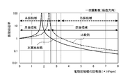
- FIG. 12 is a graph showing the relationship between the rotational speed of the electric compressor 10 and the vibration transmissibility (vertical direction).
- the vibration acceleration in the vicinity of the suction port 15 and the vicinity of the discharge port 16 is detected in consideration of vibrations (and associated noise) of the refrigerant piping of the vehicle air conditioner connected to them.
- the peak of vibration acceleration is shifted to the low rotation side compared to the comparative example (FIGS. 8 to 11). That is, the resonance frequency can be made lower in this embodiment than in the comparative example. Furthermore, as shown in FIG. 12, the vibration-proof region against vibrations in the vertical direction is clearly wider in the present embodiment than in the comparative example. Therefore, it turns out that this embodiment can suppress the vibration transmission from the electric compressor 10 to a vehicle rather than a comparative example.
- vibration transmission from the electric compressor 10 to the vehicle can be effectively suppressed by using the support bracket 20 having a relatively simple configuration.
- the number of elastic members can be reduced as compared with the conventional case, which contributes to the cost reduction of the entire mounting structure of the electric compressor.
- each of the elastic members 23 is disposed so as to be inclined so that the central axes Ca to Cc intersect the vertical line V passing through the gravity center position G. It is not limited.
- a support bracket may be configured as in the modification shown in FIG. 13 ((a) plan view, (b) perspective view).
- the two elastic members 23a and 23b arranged on the electric motor 12 side with respect to the center of gravity position G of the electric compressor 10 need not necessarily be arranged so as to intersect with the vertical line passing through the center of gravity position G.
- the electric compressor 10 (horizontal line H or the axis of the output shaft of the electric motor) is arranged symmetrically in the front-rear direction of the electric compressor 10 (so that its central axes Ca and Cb face the electric compressor). Just do it.
- SYMBOLS 10 Electric compressor, 11 ... Housing, 12 ... Electric motor, 13 ... Compression mechanism, 14 ... Inverter, 15 ... Intake port, 16 ... Discharge port, 20 ... Support bracket (support member), 21 ... Compressor side bracket ( Compressor side support member), 22 ... Vehicle side bracket (vehicle side support member), 23 ... Elastic member, Ca to Cc ... Central axis of elastic member, G ... Center of gravity of electric compressor
Landscapes
- Engineering & Computer Science (AREA)
- General Engineering & Computer Science (AREA)
- Mechanical Engineering (AREA)
- Chemical & Material Sciences (AREA)
- Combustion & Propulsion (AREA)
- Physics & Mathematics (AREA)
- Acoustics & Sound (AREA)
- Aviation & Aerospace Engineering (AREA)
- Compressor (AREA)
- Applications Or Details Of Rotary Compressors (AREA)
- Vibration Prevention Devices (AREA)
- Air-Conditioning For Vehicles (AREA)
Abstract
【課題】比較的簡単な構成としつつ、電動圧縮機から車両への振動伝達を効果的に抑制することのできる電動圧縮機の車両への取付構造を提供する。 【解決手段】電動モータ12、電動モータ12によって駆動される圧縮機構13及び電動モータ12を駆動するインバータ14が一体化された電動圧縮機10は、支持ブラケット20を介して車両に取り付け固定される。支持ブラケット20は、電動圧縮機10の下部に固定される圧縮機側ブラケット21と、車両に固定される車両側ブラケット22と、これらの間に配置された三つの弾性部材23とを有する。三つの弾性部材23のうちの二つは、電動圧縮機10の重心位置よりも電動モータ12側に配置され、残りの一つは重心位置よりも圧縮機構13側に配置されている。
Description
本発明は、電動モータ、電動モータによって駆動される圧縮機構及び電動モータを駆動するインバータが一体化された電動圧縮機の車両への取付構造に関する。
車両用空調装置に使用される電動圧縮機は、例えばゴム製の弾性支持部材を介して車両に取り付けられており、通常は、四つの弾性支持部材が用いられている。また、電動圧縮機の圧縮機構側を支持する弾性支持部材の共振周波数と、電動圧縮機の電動モータ側を支持する弾性支持部材の共振周波数とを適宜設定し、これによって、電動圧縮機の振動が車両に伝達してしまうこと及び車両振動が電動圧縮機に伝達してしまうことを抑制する後術も知られている(特許文献1等参照)。
ところで、近年、電気自動車やハイブリッド自動車が普及してきており、車室内の静粛性は従来に比べて格段に向上している。電動圧縮機の振動が車両に伝達されると車室内の騒音が増加する。そのため、電動圧縮機から車両への振動伝達をこれまで以上に抑制することが求められている。一方、振動伝達の抑制のために構成を複雑化することはコストアップを招くため好ましくない。
そこで、本発明は、比較的簡単な構成としつつ、電動圧縮機から車両への振動伝達を効果的に抑制することのできる電動圧縮機の取付構造を提供することを目的とする。
そこで、本発明は、比較的簡単な構成としつつ、電動圧縮機から車両への振動伝達を効果的に抑制することのできる電動圧縮機の取付構造を提供することを目的とする。
本発明の一側面によると、電動モータ、前記電動モータによって駆動される圧縮機構及び前記電動モータを駆動するインバータが一体化された電動圧縮機の車両への取付構造は、前記車両に固定されると共に三つの弾性部材によって前記電動圧縮機を弾性的に支持する支持部材を含み、前記三つの弾性部材のうちの二つは、前記電動圧縮機の重心位置よりも前記電動モータ側に配置され、残りの一つは前記重心位置よりも前記圧縮機構側に配置されている。
前記取付構造によると、電動圧縮機は、当該電動圧縮機の重心位置よりも電動モータ側に配置された二つの弾性部材と圧縮機構側に配置された一つの弾性部材とによって弾性的に支持される。これにより、構成を複雑化させることなく、電動圧縮機の防振領域を従来よりも拡大して電動圧縮機から車両への振動伝達を効果的に抑制することができる。
以下、添付図面を参照して本発明の実施形態について説明する。
図1は、本発明の一実施形態による電動圧縮機の取付構造の要部構成を示している。図1(a)は、電動圧縮機の取付構造の要部正面図であり、図1(b)は、電動圧縮機の取付構造の要部斜視図である。
図1は、本発明の一実施形態による電動圧縮機の取付構造の要部構成を示している。図1(a)は、電動圧縮機の取付構造の要部正面図であり、図1(b)は、電動圧縮機の取付構造の要部斜視図である。
本実施形態による電動圧縮機の取付構造は、車両用空調装置に使用される電動圧縮機10を電気自動車やハイブリッド自動車などの車両に取り付けるためのものであって、図1に示すように、車両のボディ(図示省略)に固定されると共に電動圧縮機10を弾性的に支持する支持ブラケット20を含む。すなわち、電動圧縮機10は、支持ブラケット20を介して車両に取り付け固定される。
電動圧縮機10は、ハウジング11を有しており、このハウジング11内には、電動モータ12、電動モータ12によって駆動される圧縮機構13、及び電動モータ12を駆動するためのインバータ14が収容されている(図1(a)参照)。つまり、電動圧縮機10は、いわゆるインバータ一体型の電動圧縮機として構成されている。
ハウジング11内において、電動モータ12と圧縮機構13とは直列に配置され、電動モータ12の出力軸12aは圧縮機構13の駆動軸(図示省略)に直結されている。電動モータ12は、例えば、DCブラシレスモータであり、圧縮機構13は、例えば、固定された固定スクロールと、可動スクロールとで構成されたスクロール型圧縮機構である。インバータ14は、ハウジング11内の一端側(図では左側)に配置されている。但し、これに限るものではなく、インバータ14の配置は任意に設定することができる。
また、ハウジング11には、前記車両空調装置の冷媒配管(図示省略)が接続される吸入ポート15及び吐出ポート16が形成されている。本実施形態において、吸入ポート15は、電動モータ12の上方に開口しており、吐出ポート16は、インバータ14とは反対の他端側(右側)の上部に開口している。
インバータ14によって電動モータ12が駆動されると、電動モータ12がその出力軸12aを介して圧縮機構4(前記可動スクロール)駆動する。これにより、電動圧縮機10は、前記車両空調装置の冷媒(低圧冷媒)を吸入ポート15から吸入して圧縮し、圧縮した冷媒(高圧冷媒)を吐出ポート16から吐出する。
支持ブラケット20は、電動圧縮機10と前記車両のボディとの間、換言すれば、電動圧縮機10の下側に配置され、電動圧縮機10を弾性的に支持する。
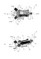
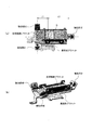
図2は、支持ブラケット20の構成を示している。図2(a)は、支持ブラケット20の平面図であり、図2(b)は、支持ブラケット20の斜視図である。
図2は、支持ブラケット20の構成を示している。図2(a)は、支持ブラケット20の平面図であり、図2(b)は、支持ブラケット20の斜視図である。
図1,図2に示すように、支持ブラケット20は、圧縮機側ブラケット21と、車両側ブラケット22と、圧縮機側ブラケット21と車両側ブラケット22との間に配置された三つの弾性部材23(23a~23c)と、を有する。
圧縮機側ブラケット21は、ボルト31及びナット32によって電動圧縮機10の下部に固定される。車両側ブラケット22は、図示省略したボルト等の締結手段によって車両のボディに固定される。弾性部材23は、例えばゴム製の部材である。
圧縮機側ブラケット21と車両側ブラケット22とは、三つの弾性部材23をその間に挟んで一体化されている。すなわち、支持ブラケット20は、車両に固定されると共に三つの弾性部材23によって電動圧縮機10を弾性的に支持するように(三点で弾性支持するように)構成されている。したがって、本実施形態において、支持ブラケット20が本発明の「支持部材」に相当し、圧縮機側ブラケット21が本発明の「圧縮機側支持部材」に相当し、車両側ブラケット22が本発明の「車両側支持部材」に相当する。
圧縮機側ブラケット21と車両側ブラケット22とは、三つの弾性部材23をその間に挟んで一体化されている。すなわち、支持ブラケット20は、車両に固定されると共に三つの弾性部材23によって電動圧縮機10を弾性的に支持するように(三点で弾性支持するように)構成されている。したがって、本実施形態において、支持ブラケット20が本発明の「支持部材」に相当し、圧縮機側ブラケット21が本発明の「圧縮機側支持部材」に相当し、車両側ブラケット22が本発明の「車両側支持部材」に相当する。
本実施形態において、圧縮機側ブラケット21及び車両側ブラケット22は、型抜きした板金部材を用いて形成されている。圧縮機側ブラケット21は、その平坦面の周縁に突設する三つの舌片部を上方に折り曲げて形成された弾性部材取付部21a~21cを有している。車両側ブラケット22は、圧縮機側ブラケット21の弾性部材取付部21a~21cに対応するように、その平坦面の周縁に突出する三つの舌片部を上方に折り曲げて形成された弾性部材取付部22a~22cを有している。弾性部材取付部21a~21c及び22a~22cには、それぞれ貫通孔が形成されている。また、本実施形態では、弾性部材23(23a~23c)として、いわゆる両ボルトタイプの丸型防振ゴム(円柱状の防振ゴム)を用いている。
各弾性部材23a~23cは、圧縮機側ブラケット21の各弾性部材取付部21a~21cと、車両側ブラケット22の各弾性部材取付部22a~22cとの間に配置される。そして、各弾性部材23a~23cの一方のボルト部を圧縮機側ブラケット21の各弾性部材取付部21a~21cの貫通孔に挿通させると共に、他方のボルト部を車両側ブラケット22の各弾性部材取付部22a~22cの貫通孔に挿通させ、その後、各ボルト部にナット33をねじ結合して締め付けることでこれらを一体化している。
但し、これに限るものではなく、圧縮機側ブラケット21と車両側ブラケット22とが三つの弾性部材23を介して一体化されて支持ブラケット20を構成していればよい。また、弾性部材23として防振スプリングや防振パッドなどを用いてもよい。
但し、これに限るものではなく、圧縮機側ブラケット21と車両側ブラケット22とが三つの弾性部材23を介して一体化されて支持ブラケット20を構成していればよい。また、弾性部材23として防振スプリングや防振パッドなどを用いてもよい。
次に、本実施形態による電動圧縮機の取付構造、特に三つの弾性部材23の配置について、図3~図6を参照して具体的に説明する。
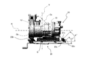
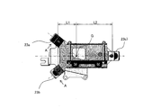
図3は、電動圧縮機の取付構造の要部正面図(図1(a)に相当)であり、図4は、電動圧縮機の取付構造の要部側面図である。また、図5は、支持ブラケット20の平面図(図2(a)に相当)であり、図6は、図5のA視図である。
図3は、電動圧縮機の取付構造の要部正面図(図1(a)に相当)であり、図4は、電動圧縮機の取付構造の要部側面図である。また、図5は、支持ブラケット20の平面図(図2(a)に相当)であり、図6は、図5のA視図である。
図3~図5に示すように、本実施形態において、三つの弾性部材23a~23cのうちの二つの弾性部材23a,23bは、電動圧縮機10の重心位置Gよりも電動モータ12側に配置され、残りの一つの弾性部材23cは、電動圧縮機10の重心位置Gよりも圧縮機構13側に配置されている。また、図3及び図4からも明らかなように、電動圧縮機10の上方から見たときに(すなわち、平面視において)、三つの弾性部材23(23a~23c)は、電動圧縮機10の外側に位置している。
ここで、電動圧縮機10の重心位置Gよりも電動モータ12側に配置された二つの弾性部材23a,23bは、電動圧縮機10(電動モータ12の出力軸12aの軸線)を挟んで電動圧縮機10の前後両外側に位置しており、電動圧縮機10の重心位置Gよりも圧縮機構13側に配置された一つの弾性部材23cは、電動圧縮機10の圧縮機構13側端面よりも外側(右側方)に位置している。
具体的には、圧縮機構13側に配置された一つの弾性部材23cは、重心位置Gを通って電動圧縮機10の左右方向(長手方向)に延びる水平線Hの下方に位置しており、電動モータ12側に配置された二つの弾性部材23a,23bは、水平線Hを挟んで電動圧縮機10の前後方向に対称に位置している。そして、電動圧縮機10の左右方向(長手方向)において、重心位置Gから電動モータ12側の弾性部材23a,23bによる圧縮機側ブラケット21の支持位置(支持点)までの距離をL1、重心位置Gから圧縮機構13側の弾性部材23cによる圧縮機側ブラケット21の支持位置(支持点)までの距離をL2としたときに、「L1:L2=1:2」となるように各弾性部材23a~23cが配置されている(図5参照)。
このような配置によって、電動圧縮機10を支持する際の各弾性部材23a~23cへの荷重配分をほぼ均等化することができ、適切な防振効果が得られると共に各弾性部材223a~23cの耐久性も向上することになる。
なお、本実施形態において、電動圧縮機10の左右方向(長手方向)は、電動モータ12の出力軸12aの軸線方向に相当し、電動圧縮機10の前後方向は、電動モータ12の出力軸12aの軸線方向に直交する水平方向に相当する。
なお、本実施形態において、電動圧縮機10の左右方向(長手方向)は、電動モータ12の出力軸12aの軸線方向に相当し、電動圧縮機10の前後方向は、電動モータ12の出力軸12aの軸線方向に直交する水平方向に相当する。
また、圧縮機側ブラケット21の各弾性部材取付部21a~21c及び車両側ブラケット22の各弾性部材取付部22a~22cは、それぞれ水平面に対して所定角度で傾斜している。具体的には、電動圧縮機10の重心位置Gよりも圧縮機構13側に位置する弾性部材取付部21c及び22cは、水平面に対して角度αで傾斜しており(図3参照)、電動圧縮機10の重心位置Gよりも電動モータ12側に位置する弾性部材取付部21a,21b,22a及び22bは、水平面に対して角度βで傾斜している(図6参照)。このため、各弾性部材23a~23cは、圧縮機側ブラケット21と車両側ブラケット22の間において、その上部がその下部よりも電動圧縮機10に近づくように傾斜して配置されるようになっている。
このように各弾性部材23a~23cを傾斜して配置すると、各弾性部材23a~23cのばね定数(ゴム硬度)を変えることなく、支持ブラケット20全体の固有振動数を低くすることができる。これにより、支持ブラケット20の防振領域を拡大して振動伝達率を小さくすることができる。なお、角度α及び角度βは、電動圧縮機10の仕様や車両の種類などに応じて任意に設定できる。但し、本実施形態では、角度α=角度β=45°としている。
さらに、本実施形態において、圧縮機側ブラケット21の各弾性部材取付部21a~21c及び車両側ブラケット22の各弾性部材取付部22a~22cは、上述の各舌片部を重心位置Gの鉛直上方に向かって折り曲げて形成されている。このため、各弾性部材23a~23cは、その中心軸Ca~Ccが、重心位置Gを通る鉛直線Vと交差するように傾斜して配置されている(図3、図4参照)。このようにすると、支持ブラケット20による電動圧縮機10の防振効果をさらに安定かつ確実に得ることができる。
なお、各弾性部材23a~23cの中心軸Ca~Ccが重心位値Gを通るようにしてもよいことはもちろんである。この場合には、角度α<角度βとなる。
なお、各弾性部材23a~23cの中心軸Ca~Ccが重心位値Gを通るようにしてもよいことはもちろんである。この場合には、角度α<角度βとなる。
次に、本実施形態による電動圧縮機の取付構造の効果を比較例と対比して説明する。
図7は、比較例における支持ブラケットを示している。この比較例における支持ブラケットは、本実施形態における支持ブラケット20が電動圧縮機10を三点で弾性支持するように構成されているのに対し、従来技術と同様に、電動圧縮機10を四点で弾性支持するように構成されたものである。
図7は、比較例における支持ブラケットを示している。この比較例における支持ブラケットは、本実施形態における支持ブラケット20が電動圧縮機10を三点で弾性支持するように構成されているのに対し、従来技術と同様に、電動圧縮機10を四点で弾性支持するように構成されたものである。
図8~図12は、本実施形態による電動圧縮機の取付構造(三点弾性支持)と、比較例(四点弾性支持)との比較結果を示している。
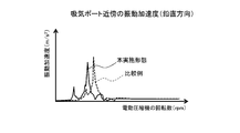
図8,図9は、電動圧縮機10の回転数と吸入ポート15近傍の振動加速度との関係を示すグラフであり、図10,図11は、電動圧縮機10の回転数と吐出ポート16近傍の振動加速度との関係を示すグラフである。また、図12は、電動圧縮機10の回転数と振動伝達率(鉛直方向)との関係を示すグラフである。ここで、吸入ポート15近傍及び吐出ポート16近傍の振動加速度を検出するのは、これらに接続される前記車両空調装置の冷媒配管の振動(及びこれに伴う騒音)を考慮したものである。
図8,図9は、電動圧縮機10の回転数と吸入ポート15近傍の振動加速度との関係を示すグラフであり、図10,図11は、電動圧縮機10の回転数と吐出ポート16近傍の振動加速度との関係を示すグラフである。また、図12は、電動圧縮機10の回転数と振動伝達率(鉛直方向)との関係を示すグラフである。ここで、吸入ポート15近傍及び吐出ポート16近傍の振動加速度を検出するのは、これらに接続される前記車両空調装置の冷媒配管の振動(及びこれに伴う騒音)を考慮したものである。
吸入ポート15近傍及び吐出ポート16近傍の双方において、本実施形態と比較例との間で水平方向の振動加速度のピーク値についてはほとんど差がないが(図8,図10)、鉛直方向の振動加速度のピーク値については本実施形態の方が比較例よりも小さくなることが確認された(図9,図11)。特に吐出ポート16近傍における鉛直方向の振動加速度のピーク値の差は大きい(図11)。したがって、本実施形態は、比較例に対して特に鉛直方向の振動を抑制できることが分かる。
また、本実施形態の方が比較例に対して振動加速度のピークが低回転側にシフトしている(図8~図11)。つまり、本実施形態の方が比較例よりもその共振周波数を低くすることができる。さらに、図12に示すように、特に鉛直方向の振動に対する防振領域が、本実施形態の方が比較例よりも明らかに広くなっている。したがって、本実施形態は、比較例よりも電動圧縮機10から車両への振動伝達を抑制できることが分かる。
このように、本実施形態によれば、比較的簡単な構成の支持ブラケット20を用いることによって、電動圧縮機10から車両への振動伝達を効果的に抑制することができる。また、従来に比べて弾性部材の個数を少なくすることができ、電動圧縮機の取付構造全体のコストダウンにも寄与する。
以上、本発明の好ましい実施形態について説明したが、本発明は上述の実施形態に制限されるものではなく、本発明の技術的思想に基づいて更なる変形等が可能であることはもちろんである。
例えば、上述の実施形態において、各弾性部材23(23a~23c)は、その中心軸Ca~Ccが重心位置Gを通る鉛直線Vと交差するように傾斜して配置されているが、これに限るものではない。図13((a)平面図、(b)斜視図)に示す変形例のように、支持ブラケットを構成してもよい。すなわち、電動圧縮機10の重心位置Gよりも電動モータ12側に配置された二つの弾性部材23a,23bについては、必ずしも重心位置Gを通る鉛直線と交差するように傾斜して配置する必要はなく、電動圧縮機10(水平線H又は電動モータの出力軸の軸線)を挟んで電動圧縮機10の前後方向に対称に(その中心軸Ca,Cbが電動圧縮機に向かうように)配置されていればよい。
例えば、上述の実施形態において、各弾性部材23(23a~23c)は、その中心軸Ca~Ccが重心位置Gを通る鉛直線Vと交差するように傾斜して配置されているが、これに限るものではない。図13((a)平面図、(b)斜視図)に示す変形例のように、支持ブラケットを構成してもよい。すなわち、電動圧縮機10の重心位置Gよりも電動モータ12側に配置された二つの弾性部材23a,23bについては、必ずしも重心位置Gを通る鉛直線と交差するように傾斜して配置する必要はなく、電動圧縮機10(水平線H又は電動モータの出力軸の軸線)を挟んで電動圧縮機10の前後方向に対称に(その中心軸Ca,Cbが電動圧縮機に向かうように)配置されていればよい。
10…電動圧縮機、11…ハウジング、12…電動モータ、13…圧縮機構、14…インバータ、15…吸気ポート、16…吐出ポート、20…支持ブラケット(支持部材)、21…圧縮機側ブラケット(圧縮機側支持部材)、22…車両側ブラケット(車両側支持部材)、23…弾性部材、Ca~Cc…弾性部材の中心軸、G…電動圧縮機の重心位置
Claims (6)
- 電動モータ、前記電動モータによって駆動される圧縮機構及び前記電動モータを駆動するインバータが一体化された電動圧縮機の車両への取付構造であって、前記車両に固定されると共に三つの弾性部材によって前記電動圧縮機を弾性的に支持する支持部材を含み、前記三つの弾性部材のうちの二つは、前記電動圧縮機の重心位置よりも前記電動モータ側に配置され、残りの一つは前記重心位置よりも前記圧縮機構側に配置されている、電動圧縮機の取付構造。
- 前記三つの弾性部材は、平面視において前記電動圧縮機の外側に位置している、請求項1に記載の電動圧縮機の取付構造。
- 前記重心位置よりも前記電動モータ側に配置された二つの弾性部材は、前記電動モータの出力軸の軸線を挟んで前記電動圧縮機の両外側に位置し、前記重心位置よりも前記圧縮機構側に配置された一つの弾性部材は、前記電動圧縮機の前記圧縮機構側の端面よりも外側に位置している、請求項2に記載の電動圧縮機の取付構造。
- 前記三つの弾性部材のそれぞれは、その上部がその下部よりも前記電動圧縮機に近づくように傾斜して配置されている、請求項2又は3に記載の電動圧縮機の取付構造。
- 前記三つの弾性部材は、その中心軸が前記重心位置を通る鉛直線と交差するように傾斜して配置されている、請求項4に記載の電動圧縮機の取付構造。
- 前記支持部材は、前記電動圧縮機の下部に固定される圧縮機側支持部材と、前記車両に固定される車両側支持部材と、を有し、前記三つの弾性部材が、前記圧縮機側支持部材と前記車両側支持部材との間に配置されている、請求項1~5のいずれか一つに記載の電動圧縮機の取付構造。
Priority Applications (2)
| Application Number | Priority Date | Filing Date | Title |
|---|---|---|---|
| DE112014005119.5T DE112014005119T5 (de) | 2013-11-07 | 2014-11-06 | Montagestruktur für einen elektrischen Kompressor |
| CN201480061082.9A CN105899807A (zh) | 2013-11-07 | 2014-11-06 | 电动压缩机的安装结构 |
Applications Claiming Priority (2)
| Application Number | Priority Date | Filing Date | Title |
|---|---|---|---|
| JP2013-231022 | 2013-11-07 | ||
| JP2013231022A JP2015090130A (ja) | 2013-11-07 | 2013-11-07 | 電動圧縮機の取付構造 |
Publications (1)
| Publication Number | Publication Date |
|---|---|
| WO2015068754A1 true WO2015068754A1 (ja) | 2015-05-14 |
Family
ID=53041531
Family Applications (1)
| Application Number | Title | Priority Date | Filing Date |
|---|---|---|---|
| PCT/JP2014/079404 Ceased WO2015068754A1 (ja) | 2013-11-07 | 2014-11-06 | 電動圧縮機の取付構造 |
Country Status (4)
| Country | Link |
|---|---|
| JP (1) | JP2015090130A (ja) |
| CN (1) | CN105899807A (ja) |
| DE (1) | DE112014005119T5 (ja) |
| WO (1) | WO2015068754A1 (ja) |
Cited By (4)
| Publication number | Priority date | Publication date | Assignee | Title |
|---|---|---|---|---|
| EP3217128A1 (en) * | 2016-03-07 | 2017-09-13 | Whirlpool Corporation | Refrigerator vibration isolating compressor mount |
| CN107636313A (zh) * | 2015-05-29 | 2018-01-26 | 纳博特斯克有限公司 | 空气压缩装置 |
| WO2020195512A1 (ja) * | 2019-03-28 | 2020-10-01 | 株式会社デンソー | 防振装置 |
| IT202100014276A1 (it) * | 2021-06-01 | 2022-12-01 | Cifa Spa | Apparecchiatura di pompaggio |
Families Citing this family (23)
| Publication number | Priority date | Publication date | Assignee | Title |
|---|---|---|---|---|
| CN104943507B (zh) * | 2015-06-08 | 2017-03-08 | 南京金龙新能源汽车研究院有限公司 | 一种空调压缩机安装支架 |
| JP6728599B2 (ja) * | 2015-08-28 | 2020-07-22 | 株式会社Soken | 防振装置 |
| JP2017089816A (ja) * | 2015-11-13 | 2017-05-25 | サンデン・オートモーティブコンポーネント株式会社 | 電動圧縮機の支持装置 |
| CN205605462U (zh) * | 2016-05-06 | 2016-09-28 | 艾拉斯科普库空气动力股份有限公司 | 离心式压缩机 |
| DE102016111293B4 (de) * | 2016-06-21 | 2018-10-25 | Starrag Gmbh | Einrichtung zur Kühlschmierstoffversorgung für Werkzeugmaschinen |
| US10830223B2 (en) * | 2016-11-30 | 2020-11-10 | Dare Auto Inc. | Pump system |
| FR3059733B1 (fr) * | 2016-12-05 | 2021-01-01 | Valeo Japan Co Ltd | Compresseur pour une installation de conditionnement d'air d'un vehicule automobile, equipe d'organes d'amortissement de vibrations dont les proprietes d'amortissement sont differenciees. |
| KR102485662B1 (ko) * | 2017-02-17 | 2023-01-09 | 한온시스템 주식회사 | 압축기 |
| JP6733575B2 (ja) * | 2017-02-23 | 2020-08-05 | 株式会社デンソー | 圧縮機及び冷凍サイクル装置 |
| JP6971739B2 (ja) * | 2017-09-22 | 2021-11-24 | 三菱重工サーマルシステムズ株式会社 | 輸送用冷凍機 |
| KR102577678B1 (ko) * | 2017-12-29 | 2023-09-14 | 한온시스템 주식회사 | 압축기 |
| DE102018210153A1 (de) * | 2018-06-21 | 2019-12-24 | Volkswagen Aktiengesellschaft | Entkopplungsanordnung für einen Kompressor in einem Kraftfahrzeug |
| DE102019214914A1 (de) * | 2019-09-27 | 2021-04-01 | Volkswagen Aktiengesellschaft | Halterung für einen Kompressor und Kraftfahrzeug mit einer solchen Halterung |
| PL3832134T3 (pl) * | 2019-12-04 | 2024-09-02 | Arçelik Anonim Sirketi | Sprężarka o zmiennej prędkości |
| CN111577592B (zh) * | 2020-06-18 | 2021-12-31 | 山东尤科斯石油装备有限公司 | 一种预装式压裂泵 |
| CN116018295B (zh) * | 2020-09-02 | 2025-06-10 | 采埃孚商用车系统欧洲有限公司 | 压缩机组件和空气供应单元 |
| CN116323271A (zh) * | 2020-12-11 | 2023-06-23 | 浙江吉利控股集团有限公司 | 一种用于车辆空调压缩机的悬置系统及车辆 |
| JP7488986B2 (ja) * | 2021-03-23 | 2024-05-23 | 株式会社豊田自動織機 | 電動圧縮機 |
| DE102021119801B4 (de) * | 2021-07-29 | 2025-08-07 | Vibracoustic Se | Halterung zum Fixieren eines elektrischen Kompressors |
| CN113565736B (zh) * | 2021-08-03 | 2023-03-28 | 珠海格力电器股份有限公司 | 振动设备用减振垫、减振垫组、空调器的减振组件和空调器 |
| DE102022109602B4 (de) | 2022-04-21 | 2024-08-01 | Dr. Ing. H.C. F. Porsche Aktiengesellschaft | Antriebssystem für ein wenigstens teilweise elektrisch angetriebenes Kraftfahrzeug |
| CN115263990B (zh) * | 2022-09-02 | 2025-10-24 | 重庆拓思动力科技有限公司 | 一种电驱动力单元减振装置 |
| KR20250144114A (ko) * | 2024-03-26 | 2025-10-10 | 한온시스템 주식회사 | 압축기의 설치구조 및 압축기를 지지하는 브라켓 어셈블리 |
Citations (5)
| Publication number | Priority date | Publication date | Assignee | Title |
|---|---|---|---|---|
| JPS5868594A (ja) * | 1981-10-20 | 1983-04-23 | 株式会社東芝 | 横型回転圧縮機の支持装置 |
| JPS62167892U (ja) * | 1986-04-15 | 1987-10-24 | ||
| JPH04164172A (ja) * | 1990-10-24 | 1992-06-09 | Daikin Ind Ltd | 横形圧縮機 |
| JP2000234586A (ja) * | 1998-12-17 | 2000-08-29 | Denso Corp | 電動圧縮機の取付構造 |
| US6543741B1 (en) * | 2001-12-26 | 2003-04-08 | Carrier Corporation | Vibration isolation for a transversely mounted compressor |
Family Cites Families (4)
| Publication number | Priority date | Publication date | Assignee | Title |
|---|---|---|---|---|
| JPH0599143A (ja) * | 1991-04-11 | 1993-04-20 | Mitsubishi Electric Corp | 圧縮機の防振支持装置 |
| JPH09250781A (ja) * | 1996-03-14 | 1997-09-22 | Matsushita Seiko Co Ltd | 空気調和機の圧縮機固定装置 |
| JP5313206B2 (ja) * | 2010-06-11 | 2013-10-09 | 株式会社神戸製鋼所 | スクリュ圧縮機 |
| US8944401B2 (en) * | 2010-10-19 | 2015-02-03 | Jaguar Land Rover Limited | Vibration damper of a vehicle and method of reducing vibration |
-
2013
- 2013-11-07 JP JP2013231022A patent/JP2015090130A/ja active Pending
-
2014
- 2014-11-06 WO PCT/JP2014/079404 patent/WO2015068754A1/ja not_active Ceased
- 2014-11-06 CN CN201480061082.9A patent/CN105899807A/zh active Pending
- 2014-11-06 DE DE112014005119.5T patent/DE112014005119T5/de not_active Ceased
Patent Citations (5)
| Publication number | Priority date | Publication date | Assignee | Title |
|---|---|---|---|---|
| JPS5868594A (ja) * | 1981-10-20 | 1983-04-23 | 株式会社東芝 | 横型回転圧縮機の支持装置 |
| JPS62167892U (ja) * | 1986-04-15 | 1987-10-24 | ||
| JPH04164172A (ja) * | 1990-10-24 | 1992-06-09 | Daikin Ind Ltd | 横形圧縮機 |
| JP2000234586A (ja) * | 1998-12-17 | 2000-08-29 | Denso Corp | 電動圧縮機の取付構造 |
| US6543741B1 (en) * | 2001-12-26 | 2003-04-08 | Carrier Corporation | Vibration isolation for a transversely mounted compressor |
Cited By (10)
| Publication number | Priority date | Publication date | Assignee | Title |
|---|---|---|---|---|
| CN107636313A (zh) * | 2015-05-29 | 2018-01-26 | 纳博特斯克有限公司 | 空气压缩装置 |
| EP3306097A4 (en) * | 2015-05-29 | 2019-01-16 | Nabtesco Corporation | AIR COMPRESSION DEVICE |
| EP3217128A1 (en) * | 2016-03-07 | 2017-09-13 | Whirlpool Corporation | Refrigerator vibration isolating compressor mount |
| US10359225B2 (en) | 2016-03-07 | 2019-07-23 | Whirlpool Corporation | Refrigerator vibration isolating compressor mount |
| US10859306B2 (en) | 2016-03-07 | 2020-12-08 | Whirlpool Corporation | Refrigerator vibration isolating compressor mount |
| WO2020195512A1 (ja) * | 2019-03-28 | 2020-10-01 | 株式会社デンソー | 防振装置 |
| JP2020165440A (ja) * | 2019-03-28 | 2020-10-08 | 株式会社Soken | 防振装置 |
| JP7207081B2 (ja) | 2019-03-28 | 2023-01-18 | 株式会社Soken | 防振装置 |
| IT202100014276A1 (it) * | 2021-06-01 | 2022-12-01 | Cifa Spa | Apparecchiatura di pompaggio |
| EP4098871A1 (en) * | 2021-06-01 | 2022-12-07 | Cifa S.P.A. | Pumping apparatus |
Also Published As
| Publication number | Publication date |
|---|---|
| DE112014005119T5 (de) | 2016-07-28 |
| JP2015090130A (ja) | 2015-05-11 |
| CN105899807A (zh) | 2016-08-24 |
Similar Documents
| Publication | Publication Date | Title |
|---|---|---|
| WO2015068754A1 (ja) | 電動圧縮機の取付構造 | |
| JP6377767B2 (ja) | 電動圧縮機 | |
| CN104870227B (zh) | 用于电子设备的车载结构 | |
| JP5891971B2 (ja) | 圧縮機の取付け構造 | |
| US7819638B2 (en) | Compressor mounting system | |
| JP5556721B2 (ja) | 電動圧縮機 | |
| CN103974842A (zh) | 车辆扭矩杆和用于动力单元的支撑结构 | |
| JP5446709B2 (ja) | ハイブリッド車におけるエアコン用コンプレッサの配置構造 | |
| JP6094497B2 (ja) | 電動圧縮機、及び電動圧縮機の製造方法 | |
| CN114829176A (zh) | 逆变器外壳上的安装件 | |
| US20230032188A1 (en) | Holder for fixing an electric compressor | |
| JP2010158991A (ja) | 電動圧縮機の配置構造 | |
| CN207334978U (zh) | 空调室外机和具有其的空调器 | |
| JP6506030B2 (ja) | 電動圧縮機の取付構造 | |
| WO2012114438A1 (ja) | ハイブリッド車におけるエアコン用コンプレッサの配置構造 | |
| JP2017089816A (ja) | 電動圧縮機の支持装置 | |
| KR102273426B1 (ko) | 전동 압축기 | |
| JP2012211531A (ja) | 電動圧縮機 | |
| KR20110098313A (ko) | 차량의 공기조화기용 전동식압축기의 마운팅구조 | |
| KR100931043B1 (ko) | 차량용 트랜스미션 마운팅 유닛 | |
| JP7257795B2 (ja) | 車両 | |
| JP6245021B2 (ja) | 補機取付構造 | |
| JP6573543B2 (ja) | スクリュ圧縮機 | |
| KR102764200B1 (ko) | 전동 압축기 | |
| KR20110051940A (ko) | 전동 컴프레서의 장착 구조 |
Legal Events
| Date | Code | Title | Description |
|---|---|---|---|
| 121 | Ep: the epo has been informed by wipo that ep was designated in this application |
Ref document number: 14860395 Country of ref document: EP Kind code of ref document: A1 |
|
| WWE | Wipo information: entry into national phase |
Ref document number: 112014005119 Country of ref document: DE Ref document number: 1120140051195 Country of ref document: DE |
|
| 122 | Ep: pct application non-entry in european phase |
Ref document number: 14860395 Country of ref document: EP Kind code of ref document: A1 |