WO2015068716A1 - マスタスレーブシステム - Google Patents
マスタスレーブシステム Download PDFInfo
- Publication number
- WO2015068716A1 WO2015068716A1 PCT/JP2014/079304 JP2014079304W WO2015068716A1 WO 2015068716 A1 WO2015068716 A1 WO 2015068716A1 JP 2014079304 W JP2014079304 W JP 2014079304W WO 2015068716 A1 WO2015068716 A1 WO 2015068716A1
- Authority
- WO
- WIPO (PCT)
- Prior art keywords
- master
- slave
- robot
- force
- displacement
- Prior art date
Links
Images


Classifications
-
- B—PERFORMING OPERATIONS; TRANSPORTING
- B25—HAND TOOLS; PORTABLE POWER-DRIVEN TOOLS; MANIPULATORS
- B25J—MANIPULATORS; CHAMBERS PROVIDED WITH MANIPULATION DEVICES
- B25J3/00—Manipulators of master-slave type, i.e. both controlling unit and controlled unit perform corresponding spatial movements
- B25J3/04—Manipulators of master-slave type, i.e. both controlling unit and controlled unit perform corresponding spatial movements involving servo mechanisms
-
- B—PERFORMING OPERATIONS; TRANSPORTING
- B25—HAND TOOLS; PORTABLE POWER-DRIVEN TOOLS; MANIPULATORS
- B25J—MANIPULATORS; CHAMBERS PROVIDED WITH MANIPULATION DEVICES
- B25J13/00—Controls for manipulators
- B25J13/02—Hand grip control means
- B25J13/025—Hand grip control means comprising haptic means
-
- B—PERFORMING OPERATIONS; TRANSPORTING
- B25—HAND TOOLS; PORTABLE POWER-DRIVEN TOOLS; MANIPULATORS
- B25J—MANIPULATORS; CHAMBERS PROVIDED WITH MANIPULATION DEVICES
- B25J9/00—Programme-controlled manipulators
- B25J9/16—Programme controls
- B25J9/1602—Programme controls characterised by the control system, structure, architecture
- B25J9/1607—Calculation of inertia, jacobian matrixes and inverses
-
- B—PERFORMING OPERATIONS; TRANSPORTING
- B25—HAND TOOLS; PORTABLE POWER-DRIVEN TOOLS; MANIPULATORS
- B25J—MANIPULATORS; CHAMBERS PROVIDED WITH MANIPULATION DEVICES
- B25J9/00—Programme-controlled manipulators
- B25J9/16—Programme controls
- B25J9/1679—Programme controls characterised by the tasks executed
- B25J9/1689—Teleoperation
-
- G—PHYSICS
- G05—CONTROLLING; REGULATING
- G05B—CONTROL OR REGULATING SYSTEMS IN GENERAL; FUNCTIONAL ELEMENTS OF SUCH SYSTEMS; MONITORING OR TESTING ARRANGEMENTS FOR SUCH SYSTEMS OR ELEMENTS
- G05B2219/00—Program-control systems
- G05B2219/30—Nc systems
- G05B2219/40—Robotics, robotics mapping to robotics vision
- G05B2219/40333—Singularity, at least one movement not possible, kinematic redundancy
Definitions
- the present invention relates to a master-slave system to which force progressive bilateral control is applied.
- the so-called master-slave system starts with a mechanical master-slave system in which a master robot and a slave robot are mechanically coupled and linked.
- the mechanical master-slave system has the advantage that the operator can get a direct feeling of operation, but the freedom of mechanical design is limited due to the geometrical constraints between the operator and the master robot and slave robot, Since the driving source is human power, the operation has to be heavy, and there are also disadvantages in that it is difficult to ensure safety in the event of an abnormality.
- the master robot and slave robot are electrically interconnected and mechanically separated so that both can operate independently.
- the master-slave system is the mainstream.
- the electric type allows flexibility in designing electric or software means, allows the mechanism to be designed flexibly, and does not allow the operator to enter the work area of the high-power actuator. It is possible to build a system that is easy to secure.
- the electric master-slave system with such features has been developed mainly for remote operation (teleoperation), so far it has improved position and force reproducibility, transparency, or communication time delay. Research has been conducted as the main focus. Hereinafter, basic bilateral control in the electric master-slave system will be described in an overview.
- f m (t) is a master operating force that the operator applies to the master robot at time t
- f s (t) is a slave operating force that the slave robot similarly applies to the environment (work target) at time t.
- q m (t) and q s (t) are joint displacements
- ⁇ m (t) and ⁇ s (t) are joint driving forces
- M m (q m ) M s (q s) is the inertia matrix
- r m (q ⁇ m, q m) r s (q ⁇ s, q s) is a remainder term which integrates the effects other than inertia.
- J m (q m ) and J s (q s ) are Jacobian matrices expressing differential kinematics and satisfy the following relationship.
- x m (t) and x s (t) are displacements in the work coordinate system of the operation end of the master robot and the work end of the slave robot corresponding to q m (t) and q s (t), respectively.
- descriptions such as “(t)” indicating an independent variable of a function may be omitted.
- Symmetric bilateral control is a master-slave bi-directional displacement error servo. Since this control does not require a force sensor, a relatively stable system can be easily configured. If proportional control in the work coordinate system is used, the control law of the master robot and the control law of the slave robot are as follows, for example. Kp is a position control gain. Also, the S f scale ratio of the force from the master robot to the slave robots, the S p is the scale ratio of the displacement from the slave robot to the master robot.
- slave dynamics (2) From the master dynamics (1), slave dynamics (2), master control law (5), and slave control law (6), the following equation is obtained.
- the influence of the master dynamics is added to the master operating force f m at the same magnification, and the influence of the slave dynamics and the slave work force f s are added at S f ⁇ 1 times.
- the force feedback type bilateral control with disposing the operation force sensor that detects the master operating force f m to the operation end of the master robot, placing the work force sensor for measuring the slave working force f s to the working end of the slave robot And configure the force error servo on the master side.
- the master control law is as follows. The above equation is obtained by adding a force error servo to the force reverse feed type master control law (8). Kf is a force control gain.
- the slave control law is the same as the equation (6) in the symmetric bilateral control.
- I is a unit matrix.
- Non-Patent Document 1 proposed parallel bilateral control that improved the conventional serial connection method of bilateral control.
- the operation force sensor that detects the master operating force f m to the operation end of the master robot
- the displacement error servo is configured in parallel with the master and slave.
- the control law is as follows, for example.
- X d (t) is a target displacement in the work coordinate system of the operation end of the master robot and the work end of the slave robot at time t.
- the force progressive bilateral control instead of slave robot measures the slave working force f s to be applied to the environment (work object), the operator measures the master operating force f m applied to the master robot
- force information is transmitted sequentially from the master to the slave, and displacement information is transmitted backward from the slave to the master.
- the force sequential bilateral control has the following features 1 to 6.
- feature 1 Since information on the slave work force f s is not required, the present invention can be applied to a system in which a work force sensor cannot be mounted on the slave robot.
- feature 2 Rather than displacement errors of the master robot, since the operator system is driven by the master operation force f m applied to the master robot, Backdrivability the master robot are not required, as a result, the master robot against human power A robust and highly accurate mechanism can be obtained.
- feature 3 Since the control is aimed at “projection”, which will be described later, instead of transparency, the operator feels not only the dynamics of the environment (work target) but also the slave dynamics and not the master dynamics.
- a slave robot is provided with a high output actuator. Therefore, the slave robot must be hardware that can withstand this high output.
- a multi-axis force sensor as a work force sensor is generally delicate and expensive, it is difficult to mount it on the work end of a high-power slave robot.
- the slave robot In the case of a master-slave system as a surgical robot, the slave robot needs to invade the human body, and its hardware is required to have a high level of cleaning, disinfection, and sterilization (autoclave sterilization). It is difficult to mount a multi-axis force sensor, which is a complicated electronic device, at the working end of such a slave robot.
- force progressive bilateral control it is only necessary to mount a force sensor (operation force sensor) on a master robot that does not have such mounting difficulties.
- the slave robot can have a simple configuration with only an actuator and a displacement sensor and no more. From the above, the force progressive bilateral control can be implemented relatively easily in many systems.
- exoskeleton projection By realizing exoskeleton projection, a slave robot that should operate mechanically independently from the master robot at least other than the trunk, feels like it is mechanically interlocked with the master robot in parts other than the trunk. The operator can feel it. Furthermore, the master robot, which is only an operating device, is erased, and the slave robot, which is the working device, gives the operator the feeling as if it were an actual exoskeleton Can do.
- exoskeleton projection is derived from this effect.
- an “ideal response” synonymous with transparency is defined as follows. “When the operator applies a certain operating force, the position responses x m and x s of the master arm and the slave arm always match the force responses f m and f s regardless of the object to be handled.” The ideal response can be expressed as follows according to the notation of the present specification in consideration of the scale ratio (S f , S p ).
- Non-Patent Document 2 The state in which this ideal response is realized is referred to as a state in which object teleperception is possible in Non-Patent Document 2.
- all the dynamics of the master-slave system must be erased together with inertia, and the load on the control system is large, and there is a high possibility that bilateral control will become unstable ( Non-Patent Document 3).
- force transparency (22) in the force feedback bilateral control equation (11) or the parallel bilateral control equation (16) the force control gain K f ⁇ ⁇ must be used. It can be understood from what is not.
- the state where this ideal response is realized is “exoskeleton projection”. There is no need to erase slave dynamics to achieve exoskeleton projection. This is particularly advantageous in a power amplification master / slave system.
- the slave robot of the power amplification master-slave system is often larger than the master robot, and the slave robot is dominant in inertia. Reducing the load of eliminating the inertia of the dominant slave robot contributes to improving the stability of the control system.
- the projectability as a norm is especially when the operator learns “machine-friendly operation” in a master-slave system (different structure, different degrees of freedom, and different scales) that have a very different dynamic between the master robot and slave robot. Is more advantageous than transparency.
- the scale effect of the slave dynamics as well as the environment (work target) is presented to the operator by using projectivity as a standard. can do.
- projectivity As a standard. can do.
- the scale effect of inertia that occurs when the slave robot is larger than the master robot (specifically, when the slave robot tries to move due to inertia, the master robot is swung around). Therefore, it is possible to prompt the operator to perform an appropriate operation, and the efficiency and optimization of the operation based on the operator's own skill can be expected.
- the scale effect of slave dynamics is not presented to the operator, and thus the efficiency and optimization of the operation by the operator cannot be expected.
- Equations (25) to (27) are the dynamics of the master robot that is only an operating device when the slave robot receives an external force ⁇ f s in the conventional bilateral control (symmetric type, force reverse feed type, force feedback type). It shows that the slave robot operates under the influence of. Then, in some cases, unstable behavior in a master-slave system by only an external force -f s applied to the slave robot at risk of being excited. Although the explanation is omitted, the same can be said for the parallel bilateral control. With respect to this problem, it can be seen that the system tends to exhibit unstable behavior when the operator releases his / her hand from the operation end of the master robot in force reverse feed type and force feedback type bilateral control. P. 24. In particular, when being larger force control gain K f in order to enhance the transparency in a force-feedback and parallel bilateral control, this tendency becomes strong.
- the master robot In the master-slave system, the master robot is only operated by humans, is made on a scale that is easy for humans to operate, and is placed in a comfortable environment for humans.
- slave robots are required to adopt a wide variety of hardware structures to operate in a wide variety of environments, depending on the task to be achieved.
- a hydraulic actuator may be employed instead of the electromagnetic actuator.
- a pneumatic actuator In a master-slave system as a surgical robot, a pneumatic actuator may be employed.
- the operator's intention is specified as the target position of the slave robot, and the position of the slave robot is controlled.
- force progressive bilateral control the operator's intention is specified as the target driving force of the slave robot, and the slave robot is driven.
- force progressive bilateral control employing a hydraulic / pneumatic actuator
- the slave robot is controlled in driving force by specifying a target pressure rather than a target position of the hydraulic / pneumatic actuator.
- Such pressure control of the hydraulic / pneumatic actuator is generally performed using a hydraulic / pneumatic control valve, and there is no difficulty in mounting.
- the driving force control is implemented in the force progressive bilateral control, it is not guaranteed that the operator will perform the position control of the slave robot with high accuracy, and the advanced bilateral control used by the computer It can be said that the complicated position control law has been pushed to the operator's skill. However, it is certain that the driving force control is easily implemented, and the operator's intention is accurately reflected in the slave robot as the slave driving force. Moreover, the operator can intuitively determine in the force progressive bilateral control until the controllability of the hydraulic / pneumatic actuator, which is hidden in the position control law in the conventional bilateral control, is good or bad.
- the dynamics compensation algorithm (gravity compensation, friction compensation, etc.) is superimposed on the driving force control of the slave robot.
- the operator's skill can be supported.
- force progressive bilateral control in which the slave robot is controlled in driving force, it is possible to simply superimpose control laws, and the enormous driving force control base has been cultivated so far.
- Knowledge can be used to support operator skills. For example, it is possible to apply such that the slave robot's non-linear term that makes the operation difficult to operate while compensating for the inertia of the slave robot useful for the operation is eliminated.
- the master robot in the master-slave system requires operability, and the slave robot requires operability.
- so-called ergonomic master robot design is required, and in order to improve workability, slave robot design that matches the task to be achieved is required.
- slave robot design that matches the task to be achieved is required. For this reason, the structures of the master robot and the slave robot are naturally different.
- a master-slave system having a master robot and a slave robot with different structures is called a different-structure master-slave system.
- a singularity problem arises when the robot is position-controlled in the work coordinate system.
- a singular point is a posture (singular posture) of a robot in which the Jacobian matrix is not regular (an inverse matrix cannot be obtained).
- the movement direction of the robot in the work coordinate system is limited.
- the joint speed for realizing the target trajectory becomes excessive. Since an actual robot can generate only a finite joint speed, position control in the work coordinate system may fail near the singular point. This is the singularity problem.
- Even if the position control law does not go through the inverse matrix of the Jacobian matrix as in the equation (6), the position control fails in the vicinity of the singular point. This is a physical failure associated with coordinate transformation. For this reason, this failure of position control cannot be prevented by a device of calculation.
- the slave robot In the conventional master-slave system, the slave robot is subjected to position control. If this is used as position control in the work coordinate system, a singularity problem occurs. That is, if the vicinity of the singular point is not avoided, the position control is broken in the vicinity of the singular point. On the other hand, if you dislike the failure and the slave robot moves around the singularity, i) The work area of the slave robot becomes narrower, and the robot becomes larger than necessary. ii) The singularity of the slave robot cannot be actively used to accomplish the task. Another disadvantage occurred, and it was not easy to eliminate it. Note that the method of positively using singular points is described in detail in Non-Patent Document 5.
- Non-Patent Document 7 proposes a method of adjusting the assist gain in accordance with the distance (operability) from the singular point in order to solve the singular point problem in the different structure master-slave system.
- Each of these is a method of informing the operator that the singular point is approached by increasing the operational feeling in the vicinity of the singular point, and is a kind of technique for avoiding the singular point. That is, even when the methods of Non-Patent Document 6 and Non-Patent Document 7 are used, the above demerits i) and ii) are still not solved.
- Non-patent document 8 proposes a singularity matching method as another countermeasure against the singularity problem.
- This method is a control method using a cofactor matrix of a Jacobian matrix, and according to this method, an excessive joint speed is suppressed and position control does not fail.
- the above disadvantages i) and ii) are also eliminated.
- the joint speed is still finite, and operability deterioration is inevitable in the vicinity of the singular point.
- Non-Patent Document 8 is devised to prevent the operability from being deteriorated, but even if the deterioration can be suppressed, it is impossible to prevent the deterioration as long as the method of Non-Patent Document 8 is used.
- force progressive bilateral control position control is not performed on the slave robot, but driving force control is performed.
- the driving force control is implemented in the slave robot as shown in Equation (19)
- force progressive bilateral control where the driving force is controlled by the slave robot, there is no singularity problem in the slave robot in the first place, so there is no need to avoid the singularity of the slave robot, and the above problems i) and ii) exist. do not do.
- i ′) The entire movable range (all work areas) of the slave robot can be used.
- ii ′) The singularity of the slave robot can be actively used to accomplish the task. The advantage is obtained.
- position-force loop is shown as control opposite to the force reverse feed type and force feedback type bilateral control, but there is no further detailed description regarding this control in the same document. This control is not considered to be a control corresponding to the force progressive bilateral control.
- the force progressive bilateral control has many advantages over the conventional bilateral control, but has the following problems that need to be solved.
- the present invention has been made in view of such circumstances, and the object of the present invention is to provide a master-slave system capable of solving the singularity problem of both the master robot and the slave robot.
- the present inventor i) Since the size of the master robot is at most human-sized, even if the design includes the entire human operation area within the operation area excluding the vicinity of the singular point of the master robot, the master robot will not become larger than necessary. . ii) The output required of the master robot is at most human-powered, and as described in [Feature 2], the force-feed type bilateral control makes the master robot a robust mechanism with a high reduction ratio. Therefore, there is no need to actively use the singularity of the master robot.
- the master slave system is A master robot that is an admittance type force sense presentation device operated by an operator, and a slave robot that is at least electrically connected to the master robot and mechanically independent from the master robot at least other than the trunk
- a bilaterally controlled master-slave system comprising: Measuring at least one master actuator for generating a master driving force for controlling the position of the master robot; at least one slave actuator for generating a slave driving force for controlling the driving force of the slave robot; and measuring a master displacement in the master robot.
- At least one master displacement sensor At least one slave displacement sensor for measuring slave displacement in the slave robot; at least one operation force sensor for measuring a master operation force applied by the operator to the master robot; and the slave
- a master target displacement calculation device that obtains a master target displacement that is a target value of the master displacement corresponding to the slave displacement by mapping the displacement, and a slave that is a target value of the slave driving force based on the master operating force.
- the slave actuator includes a slave target driving force computing unit for determining the target driving force, and
- the slave actuator generates the slave driving force based on the slave target driving force, while the master actuator generates the master driving force based on the master target displacement and the master displacement, (1)
- a work force sensor for the bilateral control that measures the slave work force applied to the environment by the slave robot is not required, and (2) the operator feels the slave dynamics without making the operator feel the master dynamics.
- the mapping in the master target displacement calculation device in advance so that the set of master target displacements does not include the singular point of the master robot, (3) the slave robot, the master robot, Regardless of whether they have the same structure or different structures, the singularity problem of both the master robot and the slave robot can be solved over the entire movable range of the slave robot.
- the master target displacement calculation device obtains the master target displacement corresponding to the slave displacement in the master joint coordinate system of the master robot by inverse kinematics calculation of the master robot. It is preferable that position control of the master robot by an actuator is performed in the master joint coordinate system.
- the master-slave system may be configured such that the master robot mechanism can perform the inverse kinematic operation of the master robot analytically without requiring a numerical iterative convergence operation.
- the master robot has six degrees of freedom or less, and three consecutive degrees of freedom of the six or less degrees of freedom constitute a single serial link mechanism.
- a configuration in which the rotation axes of the three rotation joints or their extension lines intersect at one point can be considered.
- the master robot is selected from a plurality of master robots, and a plurality of slave robots that can be electrically connected to any of the plurality of master robots.
- each of the selected one of the master robot and the slave robot is electrically connected.
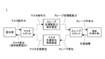
- FIG. 1 is a schematic diagram of a force progressive master-slave system according to the present invention.
- FIG. It is a control block diagram of a force progressive master slave system according to the present invention. It is the schematic which shows an example of the master arm of the force progressive type master slave system which concerns on this invention. It is the schematic which shows an example of a master arm unsuitable as a master arm of the force progressive master slave system which concerns on this invention.
- force progressive master slave systems (more precisely, master slave systems to which force progressive bilateral control is applied) 1 according to the present invention are provided at different positions of the trunk B.
- a master robot including a master arm M and a slave robot including a slave arm S which are electrically connected to each other in the following manner.
- the master arm M is an admittance type force sense presentation device operated by an operator U.
- Each of the master arm M and the slave arm S has a grip G serving as an operation end and a work end d on one end side, and the other end side is provided at a different position on the trunk B.
- Each of the master arm M and the slave arm S has two links, one end connected to the grip G or the work end d, the other end connected to the trunk B, and a connection portion between the links.
- Each has one joint (for example, a rotating joint). Therefore, each of the master arm M and the slave arm S has three degrees of freedom.
- the force progressive master slave system 1 includes a position control system PC m , a master target displacement calculation device 2, a drive force control system FC s and a slave target drive force calculation device 3. It has been.
- the master robot includes the master arm M, the master displacement sensors Pm 1 to 3 , the master actuators Am 1 to 3 , the operation force sensor F m (grip G), and the position control system PC m. It is assumed that the arm S, the slave displacement sensors Ps 1 to 3 , the slave actuators As 1 to 3 , and the driving force control system FC s are included in the slave robot.
- the operation force sensor F m is provided on the master arm M and measures the master operation force f m from the operator U.
- Master displacement sensors Pm 1 to 3 are provided at each joint of the master arm M, and measure master displacements q m and x m .
- Slave displacement sensors Ps 1 to 3 are provided at the joints of the slave arm S, and measure slave displacements q s and x s .
- Master target displacement computing unit 2 is determined by calculating the master target displacement as a target value of the master displacement q m and x m, based on the measured slave displacement q s and x s.
- the slave target driving force calculating unit 3 is determined by calculating the slave target driving force, which is the target value of the slave driving force tau s (to be described later) based on the measured master operating force f m.
- the slave actuators Ps 1 to 3 are provided at the respective joints of the slave arm S, and generate the slave driving force ⁇ s through the slave driving force control system FC s based on the slave target driving force, whereby the slave arm S controls the driving force. Is done.
- the master actuators Am 1 to 3 are provided at the respective joints of the master arm M, and generate the master driving force ⁇ m based on the master displacements q m and x m and the master target displacement, whereby the master arm M is positioned. Be controlled. More specifically, the master actuators Am 1 to 3 perform the master driving force through the position control system PC m so that the deviation between the signals from the master displacement sensors Pm 1 to 3 and the signal from the master target displacement calculation device 2 becomes zero. ⁇ m is generated.
- the slave arm S 1 to 3 that generates the slave driving force ⁇ s controls the driving force of the slave arm S, while the master actuator that generates the master driving force ⁇ m.
- the position of the master arm M is controlled by Am 1 to 3 .
- FIG. 2 is a control block diagram representing this configuration.
- the master robot in FIG. 2 includes a master arm M, master displacement sensors Pm 1 to 3 , master actuators Am 1 to 3 , an operation force sensor F m (grip G), and a position control system PC m .
- the slave robot includes a slave arm S, slave displacement sensors Ps 1 to 3 , slave actuators As 1 to 3 , and a driving force control system FC s .
- the basic force-forwarding master-slave system proposed by the present inventor in Patent Document 1 and the force-forwarding master-slave system 1 according to the present invention differ in the calculation in the master target displacement calculation device 2. More specifically, the master target displacement calculation device 2 of the force progressive master-slave system 1 according to the present invention is a mapping previously defined so that the set of master target displacements x md does not include the singular point of the master robot. A master target displacement x md corresponding to the slave displacement x s is obtained using ⁇ .
- the following master control law is used instead of the master control law (18).
- the slave control law the above-described slave control law (19) is used as it is.
- the master target displacement x md ⁇ (x s ) corresponding to the slave displacement x s can be obtained while avoiding the vicinity of the singular point of the master robot. Thereby, the singularity problem of both the master robot and the slave robot can be solved.
- mapping ⁇ is defined not only by mere scale conversion (enlargement / reduction) and parallel movement, but also by linear conversion with rotation / shear applied by so-called affine conversion. do it.
- mapping ⁇ can be defined by projective transformation or appropriate nonlinear transformation.
- p. 78-85 describes a method for associating a master operation area with a slave work area in a different-structure master-slave system. This is a method of matching the approximate direction of motion, and cannot solve the singularity problem as in the present invention.
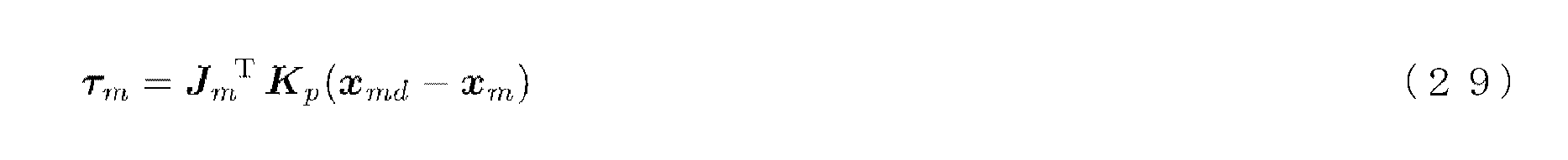
- the position control of the master robot is performed in the work coordinate system according to the master control law (29).
- the master robot is controlled according to the master control law (33).
- Position control can also be performed in the joint coordinate system.
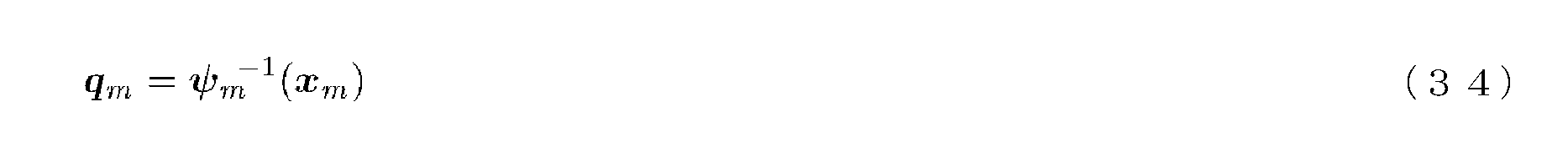
- the master joint displacement q m and the target value of the master target joint displacement q md are as follows. Since the master joint displacement q m is equivalent to the posture of the master robot, q m may be referred to as a posture in this specification.
- ⁇ m ⁇ 1 is a nonlinear function representing the inverse kinematics of the master robot.
- the mapping ⁇ is defined to cover all the slave work area X s while avoiding the singular point of the master robot, so that the inverse kinematics ⁇ m ⁇ 1 ( ⁇ (x s ) ) Always has a solution.
- the gain J m T K p for the displacement error in the work coordinate system is the master robot. It will vary depending on the attitude q m. That is, a gain that was appropriate in one posture may not be appropriate in another posture.
- the gain K p to the displacement error of the master joint coordinate system is constant that does not depend on the attitude q m of the master robot can be expected to improve the stability of the system.
- Non-Patent Document 10 shows that a general solution of inverse kinematics can be derived analytically if the robot to be controlled satisfies the following two conditions. i) The degree of freedom of the robot is 6 or less. ii) 3 consecutive degrees of freedom of 6 degrees or less are caused by three or more rotary joints constituting a single serial link mechanism, and rotation of the three rotary joints The axes or their extension lines meet at one point.
- the solution of the inverse kinematics ⁇ m ⁇ 1 ( ⁇ (x s )) in the master control law (33) can be derived analytically by using the master robot as such a mechanism.
- the position control of the master robot according to the master control law (33) can be performed at high speed and simply.
- the slave robot is controlled in position, so that the stability of the system is improved by using inverse kinematics, and the control is fast and simple.
- Is preferably a structure capable of analytically deriving inverse kinematics such that the slave robot satisfies the above conditions i) and ii).
- slave robots are first required to have task performance for task execution. Therefore, both a structure for realizing the required work performance and a structure for enabling inverse kinematics to be derived analytically are provided. It is difficult to plan. In this respect, since it is sufficient for the master robot to have a structure that can be easily operated by humans, it is relatively easy to make the structure capable of analytically deriving inverse kinematics and having excellent operability.
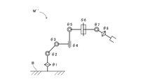
- FIG. 3 shows an example of a master robot (master arm M ′) that satisfies the above conditions i) and ii).
- the master arm M ′ includes six rotary joints indicated by ⁇ 1 to ⁇ 6, thereby having six degrees of freedom. Further, three consecutive rotary joints ⁇ 4 to ⁇ 6 among the rotary joints ⁇ 1 to ⁇ 6 constitute a serial link mechanism, and further, an extension line of the rotary shaft of the rotary joint ⁇ 4 and an extension line of the rotary shaft of the rotary joint ⁇ 6 are provided. , And intersect at one point on the rotation axis of the rotary joint ⁇ 5.
- the rotary joints ⁇ 1, ⁇ 2, and ⁇ 4 cannot be said to be continuous. Further, for example, the rotary joints ⁇ 1, ⁇ 2, and ⁇ 3 are continuous, but their rotation axes (or extension lines) do not intersect at one point.
- FIG. 4 shows an example of a master robot (master arm M ′′) that does not satisfy the above conditions i) and ii).
- the master arm M ′′ has eight degrees of freedom provided by seven rotary joints indicated by ⁇ 1 to ⁇ 3, ⁇ 5 to ⁇ 8, and one linear motion joint indicated by ⁇ 4. Therefore, the condition i) is not satisfied.
- the master arm M ′′ has three sets of three consecutive rotary joints ( ⁇ 1 to ⁇ 3, ⁇ 5 to ⁇ 7, ⁇ 6 to ⁇ 8). ) Does not meet at one point. Therefore, the master arm M ′′ does not satisfy the condition ii).
- a force progressive master-slave system includes a master robot selected from a plurality of master robots and a plurality of slave robots that can be electrically connected to any of the plurality of master robots.
- a master-slave system may be constructed by electrically connecting one selected slave robot.
- the master robot is required to have operability, and the slave robot is required to have operability.
- my master robot Since multiple slave robots can be exchanged and used accordingly, a wide variety of tasks can be achieved, such as shortening the training for skilled workers and simply replacing the end effector provided at the working end of the slave robot The advantage that it can respond to is obtained.
- This configuration is suitable for a master-slave system as a surgical robot, for example.
- the doctor selects a master robot that is well-adjusted according to his / her body, skills, and preferences.
- the doctor responds to the technique from a variety of slave robots prepared in advance. You can choose one.
- This configuration is also suitable when one master robot wants to selectively operate either a small slave robot such as a surgical robot or a large slave robot such as a power amplification robot.
- the information about the entire movable range (all work areas) of the slave robot that is, Information on slave work area set X s
- information on the entire movable range (all operation areas) and singular posture vicinity that is, master operation area set X m and all singular point neighborhoods in the master operation area
- Information of the set X mS and when one is selected and connected to each other, the mapping ⁇ is defined manually or automatically from the information, and any master robot and slave robot can be combined.
- a master-slave system can be easily constructed.
- the definition of the mapping ⁇ for example if the method to adjust the S p and x mdo of Equation (32) can be easily automated.
- Displacement and “position” in this specification mean generalized displacement, and include translation and rotation position and orientation.
- force means generalized force and includes translational force and rotational force (torque).
- each bilateral control is a simple example for explanation, and if the control purpose is not changed, a more advanced control law can be used.
- proportional control is used as the position control law.
- PID control Proxy-based Sliding Mode control that extends PID control (see Non-Patent Document 11), or Patent Document 2 that further expands it.
- Advanced control laws as described can also be used.
- the operating force sensor does not have to be a hardware force sensor.
- the operating force is estimated by an observer or the like from means for estimating the operating force from the current of the electromagnetic actuator or the pressure of the hydraulic / pneumatic actuator, or from the signal of the displacement sensor. It may be a means.
- the operation result is presented by displacement information, so the operation result is presented using a wide frequency band with DC as the lower limit and several hundred Hz to 1 kHz as the upper limit.
- the presentation of the operation result is not necessarily performed by one type of actuator.
- the operation result may be shared by a plurality of actuators having different frequency bands that can be presented.
- a combination of a plurality of actuators for example, a combination of a large motor and a small motor (so-called macro / micro system), or a combination of a motor that bears a low frequency band and a vibrator or speaker that bears a high frequency band or a voice coil motor, etc. Conceivable.
Abstract
本発明に係るマスタスレーブシステム(1)は、マスタロボットにおけるマスタ変位を計測する少なくとも一つのマスタ変位センサ(Pm1~3)と、スレーブロボットにおけるスレーブ変位を計測する少なくとも一つのスレーブ変位センサ(Ps1~3)と、前記スレーブ変位を写像することにより当該スレーブ変位に対応する前記マスタ変位の目標値であるマスタ目標変位を求めるマスタ目標変位演算装置(2)と、前記マスタ目標変位と前記マスタ変位とに基づいて、前記マスタロボットを位置制御するマスタ駆動力を発生させるマスタアクチュエータ(Am1~3)とを備える。前記写像は、前記マスタ目標変位の集合が前記マスタロボットの特異点を含まないように予め定義されている。このマスタスレーブシステム(1)によれば、マスタロボットおよびスレーブロボット双方の特異点問題を解決することができる。
Description
本発明は、力順送型バイラテラル制御が適用されるマスタスレーブシステムに関する。
いわゆるマスタスレーブシステムは、マスタロボットとスレーブロボットとが機械的に結合し、連動する機械式マスタスレーブシステムが発端となっている。機械式マスタスレーブシステムには、操作者が直接的な操作感を得られるという長所があるが、操作者とマスタロボットおよびスレーブロボットとの幾何学的拘束から機構設計の自由が制限されるとともに、駆動源が人力であることから操作が重くならざるを得ず、また、異常時における安全確保に難があるという短所も存在する。
そこで、機械式マスタスレーブシステムの有用性は認めつつも、現在においては、マスタロボットとスレーブロボットとが電気的に相互接続され、かつ機械的には分離されて、両者が独立に動作可能な電気式マスタスレーブシステムが主流となっている。一般的に、電気式とすれば、電気的またはソフトウェア的手段による融通が利き、柔軟に機構を設計することができ、しかも、大出力アクチュエータの作業領域に操作者を入れないような、安全を確保しやすいシステムを構築することが可能となる。
このような特徴を持つ電気式マスタスレーブシステムは、遠隔操作(テレオペレーション)を主なアプリケーションとして発展してきたために、これまでは、位置や力の再現性、透明性、または通信時間遅延の改善を主眼として研究がなされてきた。以下、電気式マスタスレーブシステムにおける基本的なバイラテラル制御について俯瞰的に説明する。
まず、マスタロボットおよびスレーブロボットのダイナミクスを表現する運動方程式を、説明の便宜のため、一例として以下のように定める。


fm(t)は、時刻tにおいて操作者がマスタロボットに加えるマスタ操作力、fs(t)は、同じく時刻tにおいてスレーブロボットが環境(作業対象)に加えるスレーブ作業力である。また、マスタロボットおよびスレーブロボットのそれぞれについて、qm(t)、qs(t)は関節変位、τm(t)、τs(t)は関節駆動力、Mm(qm)、Ms(qs)は慣性行列、rm(q・
m,qm)、rs(q・
s,qs)は慣性以外の効果を集約した剰余項である。Jm(qm)、Js(qs)は微分運動学を表現するヤコビ行列であり、以下の関係を満たす。


xm(t)、xs(t)は、それぞれqm(t)、qs(t)に対応するマスタロボットの操作端およびスレーブロボットの作業端の作業座標系における変位である。なお、本明細書では、関数の独立変数を示す“(t)”等の記述を省略して表記することがある。
[対称型バイラテラル制御]
対称型のバイラテラル制御は、マスタ・スレーブの双方向の変位誤差サーボである。この制御では力センサが不要となるため、比較的安定な系を簡単に構成することができる。作業座標系における比例制御を用いれば、マスタロボットの制御則およびスレーブロボットの制御則は、例えば以下のようになる。


Kpは位置制御ゲインである。また、Sfはマスタロボットからスレーブロボットへの力のスケール比、Spはスレーブロボットからマスタロボットへの変位のスケール比である。
対称型のバイラテラル制御は、マスタ・スレーブの双方向の変位誤差サーボである。この制御では力センサが不要となるため、比較的安定な系を簡単に構成することができる。作業座標系における比例制御を用いれば、マスタロボットの制御則およびスレーブロボットの制御則は、例えば以下のようになる。
マスタダイナミクス(1)、スレーブダイナミクス(2)、マスタ制御則(5)およびスレーブ制御則(6)から、次式が得られる。

このように、対称型バイラテラル制御では、マスタ操作力fmにマスタダイナミクスの影響が等倍で加わるとともに、スレーブダイナミクスの影響とスレーブ作業力fsがSf
-1倍で加わる。
[力逆送型バイラテラル制御]
力逆送型のバイラテラル制御では、スレーブロボットの作業端にスレーブ作業力fsを計測する作業力センサを配置し、スレーブ作業力fsをマスタの駆動力へ「反射」させる。この場合、マスタ制御則は次式のようになる。なお、スレーブ制御則は対称型バイラテラル制御における式(6)と同じである。

力逆送型のバイラテラル制御では、スレーブロボットの作業端にスレーブ作業力fsを計測する作業力センサを配置し、スレーブ作業力fsをマスタの駆動力へ「反射」させる。この場合、マスタ制御則は次式のようになる。なお、スレーブ制御則は対称型バイラテラル制御における式(6)と同じである。
マスタダイナミクス(1)およびマスタ制御則(8)から、次式が得られる。

対称型バイラテラル制御と同様、力逆送型バイラテラル制御では、マスタ操作力fmにマスタダイナミクスの影響が等倍で加わるとともに、スレーブ作業力fsがSf
-1倍で加わる。一方、マスタ操作力fmは、スレーブダイナミクスの影響を受けない。
[力帰還型バイラテラル制御]
力帰還型のバイラテラル制御では、マスタロボットの操作端にマスタ操作力fmを計測する操作力センサを配置するとともに、スレーブロボットの作業端にスレーブ作業力fsを計測する作業力センサを配置し、マスタ側で力誤差サーボを構成する。この場合、マスタ制御則は次式のようになる。

上式は、力逆送型のマスタ制御則(8)に力誤差サーボを追加したものである。なお、Kfは力制御ゲインである。また、スレーブ制御則は対称型バイラテラル制御における式(6)と同じである。
力帰還型のバイラテラル制御では、マスタロボットの操作端にマスタ操作力fmを計測する操作力センサを配置するとともに、スレーブロボットの作業端にスレーブ作業力fsを計測する作業力センサを配置し、マスタ側で力誤差サーボを構成する。この場合、マスタ制御則は次式のようになる。
マスタダイナミクス(1)およびマスタ制御則(10)から、次式が得られる。なお、Iは単位行列である。

上式において力制御ゲインKfを十分に大きくすれば、次式が得られる。

このように、力帰還型バイラテラル制御では、力制御ゲインKfを十分に大きくすることで、マスタ操作力fmへのマスタダイナミクスの影響は無視できる程小さくなり、マスタ操作力fmにはスレーブ作業力fsのみがSf
-1倍で加わる。ただし、実装上は力制御ゲインKfを大きくするにつれてバイラテラル制御の安定性が損なわれるため、マスタ操作力fmへのマスタダイナミクスの影響を完全に消すことは難しく、透明性を完全に実現することはできない。
[並列型バイラテラル制御]
宮崎らは、非特許文献1において、これまでのバイラテラル制御の直列的な接続方法を改良した並列型バイラテラル制御を提案した。並列型では、マスタロボットの操作端にマスタ操作力fmを計測する操作力センサを配置するとともに、スレーブロボットの作業端にスレーブ作業力fs(t)を計測する作業力センサを配置して、マスタ・スレーブで並列に変位誤差サーボを構成する。この場合、制御則は例えば以下のようになる。


なお、xd(t)は、時刻tにおけるマスタロボットの操作端およびスレーブロボットの作業端の作業座標系での目標変位である。
宮崎らは、非特許文献1において、これまでのバイラテラル制御の直列的な接続方法を改良した並列型バイラテラル制御を提案した。並列型では、マスタロボットの操作端にマスタ操作力fmを計測する操作力センサを配置するとともに、スレーブロボットの作業端にスレーブ作業力fs(t)を計測する作業力センサを配置して、マスタ・スレーブで並列に変位誤差サーボを構成する。この場合、制御則は例えば以下のようになる。
マスタダイナミクス(1)、スレーブダイナミクス(2)、マスタ制御則(13)、スレーブ制御則(14)および目標変位演算(15)から、次式が得られる。
そして、上式において力制御ゲインKfを十分に大きくすれば、次式が得られる。

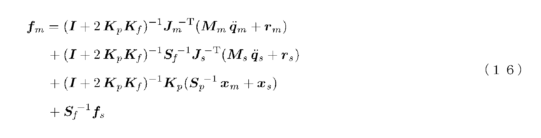
マスタ制御則とスレーブ制御則とを並列に構成することで位相遅れが減少し、バイラテラル制御の安定性が向上することが並列型バイラテラル制御の利点である。しかしながら、式(16)右辺第1項、第2項のように、並列型バイラテラル制御では、マスタ操作力fmがマスタダイナミクスおよびスレーブダイナミクスの両方の影響を受ける。さらに、式(16)右辺第3項のように、並列型バイラテラル制御では、マスタ操作力fmに元々のダイナミクスには存在しないバネ項まで付加される。力制御ゲインKfを大きくすればこれらの影響は無視できるほど小さくなるが、安定性が向上しているとはいえ、実装上は力制御ゲインKfを大きくするにつれてバイラテラル制御の安定性が損なわれるため、結局、並列型バイラテラル制御でも透明性は完全には実現できていない。
[力順送型バイラテラル制御]
ここまで、対称型、力逆送型、力帰還型および並列型を含む、基本的なバイラテラル制御について述べたが、これらをはじめとする従来のバイラテラル制御は、以下の問題1~6を有していた。
[問題1]・・・力逆送型、力帰還型および並列型に共通する問題
制御にスレーブ作業力fsの情報を必要とするため、スレーブロボットに作業力センサを実装できないシステムには適用できない。
[問題2]・・・対称型および力逆送型に共通する問題
マスタロボットの変位誤差によってシステムが駆動される制御であるため、人力で簡単にマスタロボットの変位誤差を発生することができるように、すわなち、高いバックドライバビリティが保たれるようにマスタロボットの慣性および摩擦を極力小さくしておかなければならず、高精度な機構とすることが難しい。
[問題3]・・・力帰還型および並列型に共通する問題
透明性を目指す制御であるため、操作者が主に環境(作業対象)のダイナミクスのみを感じることになる。
[問題4]・・・対称型、力逆送型、力帰還型および並列型に共通する問題
スレーブロボットが常にマスタロボットに接続されているため、操作者がマスタロボットに対して何もしなくてもスレーブロボットに加えられる外力のみによってシステムに不安定な挙動が励起される危険がある。
[問題5]・・・対称型、力逆送型、力帰還型および並列型に共通する問題
スレーブロボットへの指令値が位置であり、位置制御によってスレーブダイナミクスをキャンセルしなければならないため、制御系への負荷が大きい。さらに、位置制御ベースの制御則では、必ずしも他の制御則を重畳することができるとは限らない。
[問題6]・・・対称型、力逆送型、力帰還型および並列型に共通する問題
スレーブロボットに作業座標系での位置制御を適用すると特異点問題が生じ、スレーブロボットの姿勢が特異点近傍となったときに制御が破綻する可能性がある。
これらの問題をエレガントに解決し得る新たなバイラテラル制御として、本発明者は、特許文献1において「力順送型バイラテラル制御」の基本構成を提案した。力順送型では、マスタロボットの操作端にマスタ操作力fmを計測する操作力センサを配置し、計測したマスタ操作力fmをスレーブロボットの駆動力へ「投射」する。力順送型バイラテラル制御におけるマスタ制御則およびスレーブ制御則は、例えば以下のようになる。


スレーブダイナミクス(2)およびスレーブ制御則(19)から、次式が得られる。

このように、力順送型バイラテラル制御では、マスタ操作力fmにスレーブダイナミクスの影響とスレーブ作業力fsがSf
-1倍で加わる。すなわち、力順送型バイラテラル制御とは、スレーブロボットが環境(作業対象)に加えるスレーブ作業力fsを計測するのではなく、操作者がマスタロボットに加えるマスタ操作力fmを計測することで、マスタからスレーブへは力情報を順送し、スレーブからマスタへは変位情報を逆送する手法である。
力順送型バイラテラル制御は、以下の特徴1~6を有している。
[特徴1]
スレーブ作業力fsの情報を必要としないため、スレーブロボットに作業力センサを実装できないシステムにも適用することができる。
[特徴2]
マスタロボットの変位誤差ではなく、操作者がマスタロボットに加えるマスタ操作力fmによってシステムが駆動されるため、マスタロボットにバックドライバビリティが必要とされず、その結果、マスタロボットを人力に対して堅牢で、かつ高精度な機構とすることができる。
[特徴3]
透明性ではなく後述する「投射性」を目指す制御であるため、操作者が環境(作業対象)のダイナミクスのみならずスレーブダイナミクスをも感じ、マスタダイナミクスは感じない。
[特徴4]
操作者がマスタロボットにマスタ操作力fmを加えなければ、マスタロボットからスレーブロボットへの接続は遮断される(バイラテラルでなくなり、ユニラテラルとなる)ので、スレーブロボットに加えられる外力のみによってシステムに不安定な挙動が励起される危険はない。
[特徴5]
スレーブロボットへの指令値が位置ではなく駆動力(力とトルク)なので、スレーブ制御則の実装が容易であり、制御系への負荷が小さい。また、駆動力制御ベースの制御なので、スレーブ制御則に駆動力制御ベースのあらゆる制御を重畳することができる。
[特徴6]
スレーブロボットが位置制御ではなく駆動力制御されるので、作業座標系での制御を適用しても特異点問題が生じず、スレーブロボットの姿勢が特異点近傍となっても制御が破綻することはない。
以下、上記特徴1~6について、さらに詳しく説明していく。
まず、[特徴1]について説明する。
力逆送型、力帰還型、並列型等の従来の多くのバイラテラル制御では、マスタスレーブシステムの操作感を高めるために、スレーブロボットの作業端にスレーブ作業力fsを計測するための作業力センサを実装している。しかしながら、少なからぬシステムにおいて、スレーブロボットの作業端に作業力センサを実装することは困難である。
力逆送型、力帰還型、並列型等の従来の多くのバイラテラル制御では、マスタスレーブシステムの操作感を高めるために、スレーブロボットの作業端にスレーブ作業力fsを計測するための作業力センサを実装している。しかしながら、少なからぬシステムにおいて、スレーブロボットの作業端に作業力センサを実装することは困難である。
例えばパワー増幅マスタスレーブシステムの場合、スレーブロボットには大出力のアクチュエータが配置される。このため、スレーブロボットはこの大出力に耐えられるハードウェアでなければならない。しかしながら、一般に作業力センサとしての多軸力センサは繊細かつ高価なので、大出力スレーブロボットの作業端に実装するのは困難である。また、手術ロボットとしてのマスタスレーブシステムの場合、スレーブロボットは人体内部に侵襲することが必要であり、そのハードウェアには高いレベルの洗浄・消毒・滅菌が求められる(オートクレープ滅菌)。このようなスレーブロボットの作業端に、複雑な電子機器である多軸力センサを実装するのは困難である。
力順送型バイラテラル制御では、このような実装上の困難の無いマスタロボットにのみ力センサ(操作力センサ)を実装すればよい。一方、スレーブロボットは、アクチュエータと変位センサのみの、これ以上は無い単純な構成にすることができる。以上のことから、力順送型バイラテラル制御は、多くのシステムに比較的容易に実装可能である。
次に、[特徴2]について説明する。
従来のバイラテラル制御の多く、例えば対称型および力逆送型バイラテラル制御では、マスタロボットに加えられるマスタ操作力fmそのものではなく、マスタ操作力fmによって生じたマスタロボットの変位誤差によってシステムが駆動される。この場合、操作感を高めるためには、マスタロボットを人力でも楽に動かし得るように、いわゆるバックドライバブルにする必要があった。そして、そのために、マスタロボットの慣性質量および摩擦をできるだけ減らしておく必要があった。このような事情から、従来のバイラテラル制御では、マスタロボットが必然的に低い減速比を有する非力で華奢な機構となってしまっていた。これは、操作者に反力を高精度に提示するための剛性や出力が不足しがちであることを意味する。
従来のバイラテラル制御の多く、例えば対称型および力逆送型バイラテラル制御では、マスタロボットに加えられるマスタ操作力fmそのものではなく、マスタ操作力fmによって生じたマスタロボットの変位誤差によってシステムが駆動される。この場合、操作感を高めるためには、マスタロボットを人力でも楽に動かし得るように、いわゆるバックドライバブルにする必要があった。そして、そのために、マスタロボットの慣性質量および摩擦をできるだけ減らしておく必要があった。このような事情から、従来のバイラテラル制御では、マスタロボットが必然的に低い減速比を有する非力で華奢な機構となってしまっていた。これは、操作者に反力を高精度に提示するための剛性や出力が不足しがちであることを意味する。
これに対して力順送型バイラテラル制御では、マスタロボットに加えられるマスタ操作力fmによってシステムが駆動されるため、マスタ操作力fmさえ計測できればマスタロボットがバックドライバブルである必要はない。このため、力順送型バイラテラル制御では、マスタロボットを堅牢かつ高い減速比を有する強力な機構とすることができるとともに、操作者に反力を高精度に提示することが可能となる。なお、マスタロボットの機構は、マスタであるが故に人力程度の力に対する堅牢さが確保されていれば十分である。このため、マスタ操作力fmを計測するための操作力センサを装備していることは、たとえ操作力センサが多軸力センサであっても、堅牢さを確保する上で不利にならない。
次に、[特徴3]について説明する。
スレーブロボットに作業力センサを配置する力逆送型および力帰還型バイラテラル制御において、特に作業力センサをスレーブロボットの作業端に置く場合、式(9)や式(11)から分かるように、操作者がスレーブダイナミクスを感じることはない。一方、操作者はマスタダイナミクスを感じるため、従来のバイラテラル制御において重要な規範であった透明性は、マスタダイナミクスの影響を無視できる程小さくすることで実現されることになっていた。すなわち、従来のバイラテラル制御では、[特徴2]の説明中で述べたのとは別の理由からも、マスタロボットを低い減速比を有する非力で華奢な機構とすることが必要であった。
スレーブロボットに作業力センサを配置する力逆送型および力帰還型バイラテラル制御において、特に作業力センサをスレーブロボットの作業端に置く場合、式(9)や式(11)から分かるように、操作者がスレーブダイナミクスを感じることはない。一方、操作者はマスタダイナミクスを感じるため、従来のバイラテラル制御において重要な規範であった透明性は、マスタダイナミクスの影響を無視できる程小さくすることで実現されることになっていた。すなわち、従来のバイラテラル制御では、[特徴2]の説明中で述べたのとは別の理由からも、マスタロボットを低い減速比を有する非力で華奢な機構とすることが必要であった。
しかし、この透明性という従来のマスタスレーブシステムの規範そのものに再考の余地があると本発明者は考えており、ここに新たな規範を提唱する。すなわち、マスタダイナミクスおよびスレーブダイナミクスの両方を「透明」とし、操作者が直接、環境(作業対象)のみを操る操作感を提示するための「透明性」という従来の規範に対して、操作者によるマスタ操作力fmをスレーブ駆動力として「投射」し、環境(作業対象)のダイナミクスをも含むスレーブダイナミクスをマスタ変位として「投射」することで、環境(作業対象)と共にスレーブロボットをも操る操作感を提示するための新たな規範である。この新たな規範を「投射性」と呼ぶことにする。マスタ操作力fmが正確にスレーブ駆動力に投射されているほど、また、環境(作業対象)のダイナミクスとスレーブダイナミクスが正確にマスタ変位に投射されているほど、投射性は高いと言える。
定性的に表現すれば、透明性が高い従来のマスタスレーブシステムの場合、操作者は、マスタスレーブシステムの感覚が消えた結果、自分の身体で直接的に環境(作業対象)を操作しているように感じる。一方、投射性が高いマスタスレーブシステムの場合、操作者は、マスタロボットの感覚が消えた結果、自分の身体でスレーブロボットを動かし、そのスレーブロボットが環境(作業対象)を操作しているように感じる。つまり、透明性が「生身の身体で対象を操る感覚」を目標としているのに対し、投射性は「外骨格を介して対象を操る感覚」を目標としている、と言い換えることができる。
そこで、本発明者は、理想的な投射性が実現された状態を「外骨格投射」と名付ける。外骨格投射を実現することにより、少なくとも体幹以外はマスタロボットから機械的に独立して動作するはずのスレーブロボットが、体幹以外の部分においてもマスタロボットと機械的に連動するような感覚を操作者に感じさせることができる。さらに、操作装置に過ぎないマスタロボットの感覚を消した上で、作業装置であるスレーブロボットが、あたかも自らが実際に身に纏っている外骨格であるかのような感覚を操作者に与えることができる。「外骨格投射」の語は、このような作用効果に由来している。
横小路らは、非特許文献2のp.575において、透明性と同義の「理想応答」を以下のように定義している。
“オペレータがある操作力を加えたとき、マスタアームとスレーブアームの位置の応答xm、xsと力の応答fm、fsとが、扱う対象物によらず常に一致する。”
スケール比(Sf、Sp)を考慮した本明細書の表記に合わせれば、上記理想応答は以下のように表現することができる。


“オペレータがある操作力を加えたとき、マスタアームとスレーブアームの位置の応答xm、xsと力の応答fm、fsとが、扱う対象物によらず常に一致する。”
スケール比(Sf、Sp)を考慮した本明細書の表記に合わせれば、上記理想応答は以下のように表現することができる。
この理想応答が実現されている状態を、非特許文献2では遠隔知覚(object teleperception)できる状態と呼んでいる。ただし、このような理想応答を実現するためにはマスタスレーブシステムのダイナミクスを慣性ごと全て消去しなければならず、制御系への負荷が大きく、バイラテラル制御が不安定になる可能性が高い(非特許文献3参照)。これは、力帰還型バイラテラル制御の式(11)あるいは並列型バイラテラル制御の式(16)において力の透明性(22)を実現するためには、力制御ゲインKf→∞としなければならないことからも理解される。
これに対して、本発明者が定義した「投射性」の理想応答は以下のように表現することができる。


この理想応答が実現されている状態が「外骨格投射」である。外骨格投射を実現するためにスレーブダイナミクスを消去する必要はない。これは、パワー増幅マスタスレーブシステムにおいて、特に有利である。パワー増幅マスタスレーブシステムのスレーブロボットはマスタロボットよりも大型であることが多く、慣性もスレーブロボットが支配的である。その支配的なスレーブロボットの慣性を消去する分の負荷が軽くなることは、制御系の安定性向上に少なからず寄与する。
さらに、規範としての投射性は、特にマスタロボットとスレーブロボットとが大きく異なるダイナミクスを持つマスタスレーブシステム(異構造・異自由度・異スケール)における「機械に優しい操作」を操作者が習得する場合において、透明性よりも有利である。
例えば、マスタロボットとスレーブロボットのスケールが大きく異なる、異スケールのマスタスレーブシステムにおいては、投射性を規範とすることで、環境(作業対象)のみならずスレーブダイナミクスのスケール効果をも操作者に提示することができる。スレーブロボットがマスタロボットよりも大きい場合に生じる慣性の効果(具体的には、スレーブロボットが慣性により動き続けようとすることにより、マスタロボットが振り回されるような状態)を操作者に提示することで、操作者に適切な操作を促すことができ、操作者自身のスキルによる操作の効率化および最適化が期待できる。投射性でなく透明性を規範とするシステムではスレーブダイナミクスのスケール効果は操作者に提示されないため、このような、操作者による操作の効率化および最適化は期待できない。
以上のように、力順送型バイラテラル制御では、マスタロボットの操作端に操作力センサを配置することによって、式(20)に示されているように、マスタダイナミクスを透明とし、スレーブロボットを介して環境(作業対象)を操る感覚を操作者に提示することができる高い投射性、すなわち外骨格投射を実現することができる。また、力順送型バイラテラル制御では、式(24)で表現された力の投射性を実現するために、力制御ゲインKfを無限大にする必要はない。
次に、[特徴4]について説明する。
操作者がマスタロボットに対して何もしないマスタ操作力fm=0の場合、マスタスレーブシステムは外力-fsのみによって駆動される。対称型では式(7)より、力逆送型では式(9)より、力帰還型では式(11)より、外力-fsはそれぞれ以下のようになる。
操作者がマスタロボットに対して何もしないマスタ操作力fm=0の場合、マスタスレーブシステムは外力-fsのみによって駆動される。対称型では式(7)より、力逆送型では式(9)より、力帰還型では式(11)より、外力-fsはそれぞれ以下のようになる。
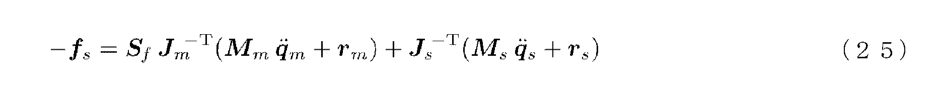
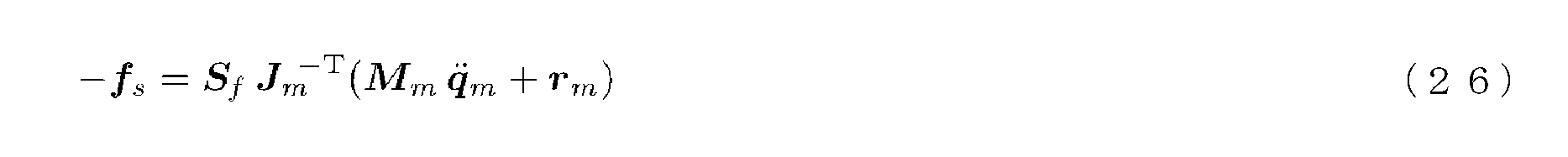
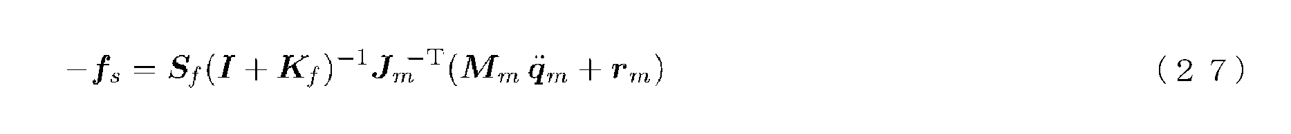
式(25)~(27)は、従来(対称型、力逆送型、力帰還型)のバイラテラル制御では、スレーブロボットが外力-fsを受けると、操作装置にすぎないマスタロボットのダイナミクスの影響下でスレーブロボットが動作することを示している。そして、場合によっては、スレーブロボットに加えられた外力-fsのみによってマスタスレーブシステムに不安定な挙動が励起される危険がある。説明は省略するが、並列型のバイラテラル制御についても同様のことが言える。この問題については、力逆送型および力帰還型バイラテラル制御において操作者がマスタロボットの操作端から手を離すと、システムが不安定な挙動を示す傾向が見られることが、非特許文献4のp.24に指摘されている。特に、力帰還型および並列型バイラテラル制御において透明性を高めるために力制御ゲインKfを大きくしていると、その傾向が強くなる。
これに対し、力順送型バイラテラル制御では、式(20)より、外力-fsは次式のようになる。

スレーブロボットは、外力-fsを受けた際に自分自身のダイナミクスの影響下で動作する。また、外力-fsがマスタダイナミクスの影響を全く受けないことから、マスタ操作力fm=0の場合は、マスタからスレーブへの接続が自動的に遮断され、力制御ゲインKfに関係なくユニラテラルとなることが分かる。このように、力順送型バイラテラル制御では、スレーブロボットに加えられる外力-fsのみによってマスタスレーブシステムに不安定な挙動が励起される危険はない。
次に、[特徴5]について説明する。
マスタスレーブシステムにおいては、マスタロボットは人間に操作されるためだけにあり、人間が操作しやすいスケールで作られ、人間にとって快適な環境下に置かれる。しかしスレーブロボットは、達成すべきタスクに応じて、多種多様な環境下で動作すべく多種多様なハードウェア構造を採用することが求められる。例えば、パワー増幅マスタスレーブシステムにおいてはスレーブロボットに大出力が求められるため、電磁アクチュエータの代わりに油圧アクチュエータが採用されることがある。また、手術ロボットとしてのマスタスレーブシステムにおいては、空圧アクチュエータが採用されることもある。そして、ほとんどの従来のバイラテラル制御では、操作者の意思はスレーブロボットの目標位置として指定され、スレーブロボットは位置制御される。
マスタスレーブシステムにおいては、マスタロボットは人間に操作されるためだけにあり、人間が操作しやすいスケールで作られ、人間にとって快適な環境下に置かれる。しかしスレーブロボットは、達成すべきタスクに応じて、多種多様な環境下で動作すべく多種多様なハードウェア構造を採用することが求められる。例えば、パワー増幅マスタスレーブシステムにおいてはスレーブロボットに大出力が求められるため、電磁アクチュエータの代わりに油圧アクチュエータが採用されることがある。また、手術ロボットとしてのマスタスレーブシステムにおいては、空圧アクチュエータが採用されることもある。そして、ほとんどの従来のバイラテラル制御では、操作者の意思はスレーブロボットの目標位置として指定され、スレーブロボットは位置制御される。
よく知られているように、電磁アクチュエータに比べ油圧/空圧アクチュエータの位置(軌道)制御性能は低い。このため、従来のバイラテラル制御を用いて操作者の意思を油圧/空圧アクチュエータに正確に反映させるためには、高度で複雑な位置制御則を適用しなければならず、実装に困難が予想される。
しかし、力順送型バイラテラル制御では、操作者の意思はスレーブロボットの目標駆動力として指定され、スレーブロボットは駆動力制御される。油圧/空圧アクチュエータを採用した力順送型バイラテラル制御では、油圧/空圧アクチュエータの目標位置ではなく目標圧力を指定することにより、スレーブロボットは駆動力制御される。このような油圧/空圧アクチュエータの圧力制御は、油圧/空圧制御弁を用いて一般的に行なわれていることであり、実装に困難はない。
もちろん、力順送型バイラテラル制御に駆動力制御を実装しても、操作者がスレーブロボットの位置制御を高精度に行なうことは保証されず、従来のバイラテラル制御でコンピュータが担っていた高度で複雑な位置制御則を、操作者のスキルに押し付けてしまっただけとも言える。しかし、駆動力制御の実装が容易であることは確かであり、操作者の意思はスレーブ駆動力として正確にスレーブロボットに反映される。しかも、従来のバイラテラル制御では位置制御則に隠されてしまう油圧/空圧アクチュエータの制御性の良し悪しまで、力順送型バイラテラル制御では操作者が直感的に判断することができる。
さらに、操作者のスキルに押し付けたものの操作者の手に余るスレーブダイナミクスの非線形性が存在するならば、ダイナミクス補償のアルゴリズム(重力補償、摩擦補償、他)をスレーブロボットの駆動力制御に重畳することで、操作者のスキルを支援することができる。スレーブロボットが駆動力制御される力順送型バイラテラル制御においては、制御則の単純な重ね合わせが可能であり、これまでロボット制御工学が営々と培ってきた成果としての駆動力制御ベースの膨大な知識を操作者のスキル支援のために利用することができる。例えば、操作に役立つスレーブロボットの慣性は操作者に感じさせつつ、操作をしにくくするスレーブロボットの非線形項は補償して消去するといった応用も可能である。あるいは、まるで外骨格上で操作者の手を取って誘導するかのようなスレーブロボットの低ゲインの軌道制御を重ね合わせたり、スレーブロボットの可動範囲を制限する仮想壁をスレーブロボット制御に重ね合わせたりすることもできる。スレーブロボットが位置制御ベースの場合は、前述の通り、このような制御則を単純に重ね合わせることができるとは限らない。
次に、[特徴6]について説明する。
マスタスレーブシステムにおけるマスタロボットには操作性が求められ、スレーブロボットには作業性が求められる。操作性向上のためには、いわゆる人間工学的なマスタロボット設計が必要であり、作業性向上のためには、達成すべきタスクに合わせたスレーブロボット設計が必要である。このため、マスタロボットとスレーブロボットの構造は、自ずと異なったものとなる。構造の異なるマスタロボットとスレーブロボットを備えたマスタスレーブシステムを、異構造マスタスレーブシステムと呼ぶ。
マスタスレーブシステムにおけるマスタロボットには操作性が求められ、スレーブロボットには作業性が求められる。操作性向上のためには、いわゆる人間工学的なマスタロボット設計が必要であり、作業性向上のためには、達成すべきタスクに合わせたスレーブロボット設計が必要である。このため、マスタロボットとスレーブロボットの構造は、自ずと異なったものとなる。構造の異なるマスタロボットとスレーブロボットを備えたマスタスレーブシステムを、異構造マスタスレーブシステムと呼ぶ。
同構造マスタスレーブシステムで操作性と作業性を共に高めるのには限界がある。このため、高度なマスタスレーブシステムは異構造とならざるを得ない。そして、異構造マスタスレーブシステムにおいては作業座標系で制御を行うのが一般的であり、本明細書におけるここまでの考察でも、作業座標系で制御を行うことを前提として制御則を構築してきた。
一般に、ロボットを作業座標系で位置制御すると特異点問題が生ずる。特異点とは、ヤコビ行列が正則とならない(逆行列が得られない)ロボットの姿勢(特異姿勢)のことである。特異点においては、作業座標系におけるロボットの運動方向が制限される。特異点近傍においては、作業座標系でロボットの目標軌道を定めた場合に、その目標軌道を実現する関節速度が過大となる。そして、現実のロボットは有限の関節速度しか発生できないため、特異点近傍においては作業座標系での位置制御が破綻する可能性がある。これが特異点問題である。たとえ式(6)のように、計算上、ヤコビ行列の逆行列を経由しない位置制御則でも、やはり特異点近傍で位置制御は破綻する。これは、座標変換に伴う物理的な破綻である。このため、この位置制御の破綻を計算の工夫によって防ぐことはできない。
従来のマスタスレーブシステムにおいてはスレーブロボットに位置制御がなされており、これを作業座標系での位置制御とすると特異点問題が発生する。つまり、特異点近傍を避けなければ、特異点近傍で位置制御が破綻してしまう。一方、破綻を嫌ってスレーブロボットが特異点近傍を避けて動くようにすると、
i)スレーブロボットの作業領域が狭くなり、必要以上にロボットが大型化する。
ii)タスク達成のために、スレーブロボットの特異点を積極的に利用することができない。
という別のデメリットが発生し、これを解消することは容易ではなかった。なお、特異点を積極的に利用する手法については、非特許文献5に詳細に記載されている。
i)スレーブロボットの作業領域が狭くなり、必要以上にロボットが大型化する。
ii)タスク達成のために、スレーブロボットの特異点を積極的に利用することができない。
という別のデメリットが発生し、これを解消することは容易ではなかった。なお、特異点を積極的に利用する手法については、非特許文献5に詳細に記載されている。
特異点問題への対策として、非特許文献6のp.476には、マスタロボットおよびスレーブロボットの各関節が可動範囲の限界や特異点に近づいた場合、逆方向へ力が働くようにマスタ側へフィードバックする方法が記載されている。また、非特許文献7では、異構造マスタスレーブシステムにおける特異点問題を解決するために、特異点からの距離(可操作度)に応じてアシストゲインを調整する方法が提案されている。これらはいずれも、特異点近傍での操作感を重くすることで操作者に特異点に近づいていることを知らせる方法であり、特異点を避ける手法の一種である。つまり、非特許文献6および非特許文献7の手法を用いても、上記デメリットi)、ii)は依然として解消されない。
特異点問題への別の対策として、非特許文献8では特異点適合法が提案されている。この手法は、ヤコビ行列の余因子行列を利用した制御法であり、この手法によれば、関節速度が過大になることが抑えられ、位置制御は破綻しなくなる。また、特異点を避けなくて済むため、上記デメリットi)、ii)も解消される。しかし、破綻はしないものの関節速度が有限であることに変わりなく、特異点近傍においては操作性の劣化が避けられない。非特許文献8では操作性を劣化させないための工夫がなされているが、劣化を抑えることはできても、劣化しないようにすることは非特許文献8の手法を使う限り不可能である。
これに対して、力順送型バイラテラル制御ではスレーブロボットに位置制御がなされず、駆動力制御がなされる。例えば、式(19)のようにスレーブロボットに駆動力制御を実装した場合は、微分運動学に基づきヤコビ行列の転置行列Js
Tさえ求められればよく、ヤコビ行列の逆行列Js
-1を求める必要はない。スレーブロボットに駆動力制御がなされる力順送型バイラテラル制御では、そもそもスレーブロボットには特異点問題が存在しないのでスレーブロボットの特異点を避ける必要はなく、上記問題i)、ii)は存在しない。言い換えると、力順送型バイラテラル制御によれば、
i’)スレーブロボットの可動範囲全域(全作業領域)を使用することができる。
ii’)タスク達成のために、スレーブロボットの特異点を積極的に利用することができる。
というメリットが得られる。
i’)スレーブロボットの可動範囲全域(全作業領域)を使用することができる。
ii’)タスク達成のために、スレーブロボットの特異点を積極的に利用することができる。
というメリットが得られる。
なお、非特許文献9のp.116では、力逆送型および力帰還型バイラテラル制御とは逆向きの制御として「position-force loop」が示されているが、同文献にはこの制御に関するこれ以上の詳細な記載がないため、この制御が力順送型バイラテラル制御に相当する制御であるとは考えられない。
また、非特許文献9のp.116には、“position-force loopの実装はうまくいかない”との記載があり、さらにその理由として、“スレーブロボットに対する力制御は不安定である”との記載がある。これらの記載は、「position-force loop」の実装は非常に困難であるか、または不可能であると考えるのが当業者の技術常識であったことを示唆している。
宮崎,萩原,"バイラテラル・マスタ・スレーブ・マニピュレータの並列型制御方式",日本ロボット学会誌,vol.7,no.5,pp.446-452,1989.
横小路,吉川,"マスタ・スレーブ型遠隔操縦システムの操作性",計測自動制御学会論文集,vol.26,no.5,pp.572-579,1990.
舘,榊,"インピーダンス制御型マスタ・スレーブシステム(I)基本原理と伝送遅れへの応用",日本ロボット学会誌,vol.8,no.3,pp.241-252,1990.
吉灘,"大形バイラテラルマニピュレータの研究",東京工業大学博士学位論文,2012.
琴坂,大滝,"多自由度ロボットにおける機構自由度の縮退を利用したアクチュエータの選択的利用",日本ロボット学会誌,vol.25,no.8,pp.1259-1265,2007.
新井,中野,"異構造マニピュレー夕間におけるバイラテラルマスタスレイブ制御",日本ロボット学会誌,vol.4,no.5,pp.469-479,1986.
吉永,下川,尾崎,"産業用ロボットアームを用いた異構造マスタ・スレーブアームの構成",日本機械学会ロボティクス・メカトロニクス講演会2008講演論文集,1A1-G16,2008.
妻木,小寺,ネンチェフ,内山,"6自由度マニピュレータの特異点適合遠隔操作",日本ロボット学会誌,vol.16,no.2,pp.195-204,1998.
Thurston L. Brooks, "Telerobotic Response Requirements," Proceedings of the IEEE International Conference on Systems, Man and Cybernetics, pp. 113-120, 1990.
D.L. Pieper, "The Kinematics of Manipulators under Computer Control," Stanford Artificial Intelligence Report, memo no. AI-72, 1968.
Ryo Kikuuwe, Satoshi Yasukouchi, Hideo Fujimoto, and Motoji Yamamoto," Proxy-Based Sliding Mode Control: A Safer Extension of PID Position Control," IEEE Transactions on Robotics, Vol.26, No.4, pp.670-683, 2010.
以上のように、力順送型バイラテラル制御は、従来のバイラテラル制御にはない多くの利点を有しているが、その一方で解決を要する以下の問題を有している。
すなわち、[特徴6]で述べた通り、力順送型バイラテラル制御ではスレーブロボットに位置制御がなされておらず、駆動力制御がなされているため、スレーブロボットに特異点問題は存在しない。しかしながら、力順送型バイラテラル制御ではマスタロボットに位置制御がなされているので、これを作業座標系での位置制御とするとスレーブロボットではなくマスタロボットに特異点問題が発生する。たとえ式(18)のように、計算上、ヤコビ行列の逆行列を経由しない位置制御則でも、座標変換に伴う物理的な破綻は存在し、やはり特異点近傍で位置制御が破綻する。
本発明はこのような事情に鑑みてなされたものであり、その課題とするところは、マスタロボットおよびスレーブロボット双方の特異点問題を解決し得るマスタスレーブシステムを提供することにある。
上記課題を解決するために鋭意検討した結果、本発明者は、
i)マスタロボットの大きさは高々人間サイズなので、マスタロボットの特異点近傍を除く操作領域内に人間の操作領域の全部が含まれる設計としても、マスタロボットが必要以上に大型化することはない。
ii)マスタロボットに求められる出力は高々人力であり、かつ、[特徴2]で述べたように、力順送型バイラテラル制御ではマスタロボットを堅牢かつ高い減速比を有する強力な機構とすることができるので、マスタロボットの特異点を積極的に利用する必要はない。
ことを見いだし、さらにこれらの知見i)、ii)から、
iii)従来のバイラテラル制御が適用されるマスタスレーブシステムとは異なり、力順送型バイラテラル制御が適用されるマスタスレーブシステムに限っては、マスタロボットが特異点近傍を避けて動くことがデメリットにはならない。
ことを見いだし、本発明を完成させるに至った。
すなわち、本発明に係るマスタスレーブシステムは、
操作者によって操られるアドミッタンス型の力覚提示装置であるマスタロボットと、前記マスタロボットに少なくとも電気的に接続され、かつ前記マスタロボットから少なくとも体幹以外が機械的に独立して動作するスレーブロボットとからなる、バイラテラル制御されるマスタスレーブシステムであって、
前記マスタロボットを位置制御するマスタ駆動力を発生させる少なくとも一つのマスタアクチュエータと、前記スレーブロボットを駆動力制御するスレーブ駆動力を発生させる少なくとも一つのスレーブアクチュエータと、前記マスタロボットにおけるマスタ変位を計測する少なくとも一つのマスタ変位センサと、前記スレーブロボットにおけるスレーブ変位を計測する少なくとも一つのスレーブ変位センサと、前記操作者が前記マスタロボットに加えるマスタ操作力を計測する少なくとも一つの操作力センサと、前記スレーブ変位を写像することにより、当該スレーブ変位に対応する前記マスタ変位の目標値であるマスタ目標変位を求めるマスタ目標変位演算装置と、前記マスタ操作力に基づいて前記スレーブ駆動力の目標値であるスレーブ目標駆動力を求めるスレーブ目標駆動力演算装置と、を備え、
前記スレーブアクチュエータが前記スレーブ目標駆動力に基づいて前記スレーブ駆動力を発生させる一方、前記マスタアクチュエータが前記マスタ目標変位と前記マスタ変位とに基づいて前記マスタ駆動力を発生させることで、(1)前記スレーブロボットが環境に加えるスレーブ作業力を計測する前記バイラテラル制御のための作業力センサを不要とし、かつ(2)前記操作者にマスタダイナミクスを感じさせることなく、スレーブダイナミクスを感じさせるようにし、
さらに、前記マスタ目標変位演算装置における前記写像を、前記マスタ目標変位の集合が前記マスタロボットの特異点を含まないように予め定義しておくことで、(3)前記スレーブロボットと前記マスタロボットとが同構造であるか異構造であるかに関わらず、前記スレーブロボットの可動範囲全域において前記マスタロボットおよび前記スレーブロボット双方の特異点問題を解決し得るようにした
ことを特徴とする。
上記マスタスレーブシステムは、前記マスタ目標変位演算装置が、前記マスタロボットの逆運動学演算によって、前記スレーブ変位に対応する前記マスタ目標変位を前記マスタロボットのマスタ関節座標系において求めることで、前記マスタアクチュエータによる前記マスタロボットの位置制御が前記マスタ関節座標系において行われることが好ましい。
また、上記マスタスレーブシステムは、前記マスタロボットの機構が、数値的な反復収束演算を必要とすることなく解析的に前記マスタロボットの逆運動学演算が行われ得るように構成されていることが好ましい。
なお、このような構成としては、例えば、前記マスタロボットが6以下の自由度を有し、前記6以下の自由度のうちの連続した3つの自由度が、単一のシリアルリンク機構を構成する3つの回転関節によってもたらされたものであり、前記3つの回転関節の回転軸またはその延長線が一点で交わるような構成が考えられる。
なお、このような構成としては、例えば、前記マスタロボットが6以下の自由度を有し、前記6以下の自由度のうちの連続した3つの自由度が、単一のシリアルリンク機構を構成する3つの回転関節によってもたらされたものであり、前記3つの回転関節の回転軸またはその延長線が一点で交わるような構成が考えられる。
また、上記マスタスレーブシステムは、前記マスタロボットが複数のマスタロボットの中から選ばれたものであり、前記スレーブロボットが前記複数のマスタロボットのいずれにも電気的に接続可能な複数のスレーブロボットの中から選ばれたものであり、前記選ばれた各1つの前記マスタロボットおよび前記スレーブロボットが電気的に接続されていることが好ましい。
本発明によれば、マスタロボットおよびスレーブロボット双方の特異点問題を解決し得るマスタスレーブシステムを提供することができる。
以下、図面を参照しながら本発明の実施形態について説明する。
図1に示すように、本発明に係る力順送型マスタスレーブシステム(正確には、力順送型バイラテラル制御が適用されるマスタスレーブシステム)1は、体幹Bの異なる位置に設けられるとともに、以下の要領で互いに電気的に接続されたマスタアームMを含むマスタロボットとスレーブアームSを含むスレーブロボットとからなる。この力順送型マスタスレーブシステム1において、マスタアームMは、操作者Uによって操られるアドミッタンス型の力覚提示装置である。
マスタアームMとスレーブアームSは、それぞれ、一端側に操作端となるグリップGと作業端dを有するとともに、他端側が体幹Bの異なる位置に備えられている。また、マスタアームMとスレーブアームSは、それぞれ、2本のリンクを有するとともに、グリップGまたは作業端dに接続される一端、体幹Bに接続される他端、およびリンク同士の接続部分に各1つの関節(一例として、回転関節)を有している。したがって、マスタアームMとスレーブアームSは、それぞれ3自由度を有している。
これらの関節には、マスタ変位センサPm1~3およびスレーブ変位センサPs1~3、マスタアクチュエータAm1~3およびスレーブアクチュエータAs1~3が備えられている。また、グリップGには、操作力センサFmが備えられている。さらに、図1に示すように、この力順送型マスタスレーブシステム1には、位置制御系PCm、マスタ目標変位演算装置2、駆動力制御系FCsおよびスレーブ目標駆動力演算装置3が備えられている。
なお、本明細書では、マスタアームM、マスタ変位センサPm1~3、マスタアクチュエータAm1~3、操作力センサFm(グリップG)、および位置制御系PCmがマスタロボットに含まれ、スレーブアームS、スレーブ変位センサPs1~3、スレーブアクチュエータAs1~3、および駆動力制御系FCsがスレーブロボットに含まれるものとする。
操作力センサFmはマスタアームMに設けられ、操作者Uからのマスタ操作力fmを計測する。マスタ変位センサPm1~3はマスタアームMの各関節に設けられ、マスタ変位qmおよびxmを計測する。また、スレーブ変位センサPs1~3はスレーブアームSの各関節に設けられ、スレーブ変位qsおよびxsを計測する。
マスタ目標変位演算装置2は、計測されたスレーブ変位qsおよびxsに基づきマスタ変位qmおよびxmの目標値であるマスタ目標変位を演算により求める。また、スレーブ目標駆動力演算装置3は、計測されたマスタ操作力fmに基づき後述するスレーブ駆動力τsの目標値であるスレーブ目標駆動力を演算により求める。
スレーブアクチュエータPs1~3は、スレーブアームSの各関節に設けられ、スレーブ目標駆動力に基づきスレーブ駆動力制御系FCsを通じてスレーブ駆動力τsを発生させ、これによりスレーブアームSが駆動力制御される。一方、マスタアクチュエータAm1~3は、マスタアームMの各関節に設けられ、マスタ変位qmおよびxmとマスタ目標変位とに基づきマスタ駆動力τmを発生させ、これによりマスタアームMが位置制御される。より詳しくは、マスタアクチュエータAm1~3は、マスタ変位センサPm1~3からの信号とマスタ目標変位演算装置2からの信号との偏差が0になるように位置制御系PCmを通じてマスタ駆動力τmを発生させる。
このように、力順送型マスタスレーブシステム1では、スレーブ駆動力τsを発生させるスレーブアクチュエータAs1~3によってスレーブアームSが駆動力制御される一方、マスタ駆動力τmを発生させるマスタアクチュエータAm1~3によってマスタアームMが位置制御される。
図2は、この構成を制御ブロック図で表現したものである。図2のマスタロボットには、マスタアームM、マスタ変位センサPm1~3、マスタアクチュエータAm1~3、操作力センサFm(グリップG)、および位置制御系PCmが含まれる。また、スレーブロボットには、スレーブアームS、スレーブ変位センサPs1~3、スレーブアクチュエータAs1~3、および駆動力制御系FCsが含まれる。
本発明者が特許文献1において提案した基本的な力順送型マスタスレーブシステムと本発明に係る力順送型マスタスレーブシステム1とは、マスタ目標変位演算装置2における演算が異なっている。より詳しくは、本発明に係る力順送型マスタスレーブシステム1のマスタ目標変位演算装置2は、マスタ目標変位xmdの集合がマスタロボットの特異点を含まないように予め定義しておいた写像φを用いて、スレーブ変位xsに対応するマスタ目標変位xmdを求める。
本発明に係る力順送型バイラテラル制御では、マスタ制御則(18)に代えて、例えば次式のマスタ制御則を用いる。
一方、スレーブ制御則は、前述のスレーブ制御則(19)をそのまま用いる。
また、本発明に係る力順送型バイラテラル制御では、マスタ目標変位演算装置2において、以下のようにして定義された写像φを用いる。
まず、マスタ操作領域の集合XmをXm∋xmとし、スレーブ作業領域の集合XsをXs∋xsとし、これらの集合間の写像φを次式のように定義する。

さらに、マスタ操作領域内の全ての特異点近傍の集合XmSを、XmS⊂Xmとする。このとき、写像φによる集合Xsの像Xmd=φ(Xs)∋xmdについて、次式が成り立つように写像φを定める。

まず、マスタ操作領域の集合XmをXm∋xmとし、スレーブ作業領域の集合XsをXs∋xsとし、これらの集合間の写像φを次式のように定義する。
このようにして定義した写像φによれば、スレーブ変位xsに対応するマスタ目標変位xmd=φ(xs)をマスタロボットの特異点近傍を回避して求めることができる。そして、これにより、マスタロボットおよびスレーブロボット双方の特異点問題を解決することができる。
なお、特異点近傍の集合XmSはマスタロボットの機構に依存するため、実装においては、マスタロボット毎に写像φを具体的に定義する必要があるが、スケール変換xmd=Spxsにxmdoだけの平行移動(オフセット)を加えてなる次式の写像φにおいて、xmdoをマスタ操作領域の中央付近に相当する位置とし、さらにスケール比Spをマスタ目標変位xmdが特異点近傍を含まなくなるまで小さくしておけば、多くの場合は事足りると予想される。

式(32)で表される簡易的な写像φで事足りない場合は、単なるスケール変換(拡大縮小)と平行移動だけではなく、いわゆるアフィン変換によって回転・剪断を加えた線形変換により写像φを定義すればよい。この他、射影変換や適当な非線形変換により写像φを定義することもできる。
なお、非特許文献4のp.78-85には、異構造マスタスレーブシステムにおいてマスタ操作領域とスレーブ作業領域とを対応させる手法が記載されているが、この手法は、「形の異なるマスタとスレーブのほぼ全動作領域で、両者のおおよその運動方向を一致させる方法」であり、本発明のように特異点問題を解決し得るものではない。
ここで、上の説明では、マスタロボットの位置制御をマスタ制御則(29)に従って作業座標系で行うこととしたが、マスタロボットの逆運動学を用いれば、例えばマスタ制御則(33)に従ってマスタ関節座標系で位置制御を行うこともできる。

ただし、マスタ関節変位qm、およびその目標値であるマスタ目標関節変位qmdは、それぞれ以下の通りである。なお、マスタ関節変位qmはマスタロボットの姿勢と等価なので、本明細書ではqmを姿勢と呼ぶこともある。

式(34)、(35)においてψm
-1は、マスタロボットの逆運動学を表す非線形関数である。前述の通り、本発明では、写像φがマスタロボットの特異点を回避しつつもスレーブ作業領域Xsを全てカバーするよう定義されているため、逆運動学ψm
-1(φ(xs))は必ず解を持つ。
マスタ制御則(29)では、作業座標系での位置制御のためにヤコビ行列Jm(qm)が用いられているので、作業座標系での変位誤差に対するゲインJm
TKpがマスタロボットの姿勢qmに依存して変化することになる。すなわち、ある姿勢において適切だったゲインが、別の姿勢においては適切でなくなる可能性がある。一方、上記のマスタ制御則(33)では、マスタ関節座標系での変位誤差に対するゲインKpがマスタロボットの姿勢qmに依存しない定数となるので、システムの安定性の向上が期待できる。
なお、マスタ制御則(33)において逆運動学ψm
-1(φ(xs))は必ず解を持つと述べたが、この解が解析的に導出できるとは限らない。特に、多くの自由度を有するリンク機構の逆運動学には一般的な解析解が存在しないことが多い。解析解が存在しない場合は、数値解法、すなわちコンピュータによる数値的な反復収束計算によって解を導出する必要があるが、この計算は制御系への負荷が非常に大きいものであった。
しかしながら、例えば産業用のロボットアームの多くは、その機構を工夫することによって数値解法に依らずに解析的に解を導出し得るようになっている。これに関し、非特許文献10には、制御対象となるロボットが以下の2つの条件を満たせば、逆運動学の一般解が解析的に導出され得ることが示されている。
i)ロボットの自由度が6以下であること。
ii)6以下の自由度のうちの連続した3つの自由度が、単一のシリアルリンク機構を構成する3つ以上の回転関節によってもたらされたものであり、かつその3つの回転関節の回転軸またはその延長線が一点で交わること。
したがって、本発明においても、マスタロボットをこのような機構とすることによって、マスタ制御則(33)における逆運動学ψm -1(φ(xs))の解を解析的に導出することができるようになり、高速かつ簡便にマスタ制御則(33)に従ったマスタロボットの位置制御を行えるようになる。
i)ロボットの自由度が6以下であること。
ii)6以下の自由度のうちの連続した3つの自由度が、単一のシリアルリンク機構を構成する3つ以上の回転関節によってもたらされたものであり、かつその3つの回転関節の回転軸またはその延長線が一点で交わること。
したがって、本発明においても、マスタロボットをこのような機構とすることによって、マスタ制御則(33)における逆運動学ψm -1(φ(xs))の解を解析的に導出することができるようになり、高速かつ簡便にマスタ制御則(33)に従ったマスタロボットの位置制御を行えるようになる。
なお、力順送型ではない従来のマスタスレーブシステムではスレーブロボットに位置制御がなされるので、逆運動学を用いてシステムの安定性を向上させ、かつ制御を高速かつ簡便なものとするためには、スレーブロボットが上記条件i)およびii)を満たすような、逆運動学が解析的に導出可能な構造であることが好ましい。しかしながら、スレーブロボットにはタスク遂行のための作業性能が第1に求められるところ、必要な作業性能を実現するための構造と、逆運動学を解析的に導出可能とするための構造との両立を図ることは困難である。この点、マスタロボットは、人間が操作し易い構造になっていれば十分なので、逆運動学を解析的に導出可能とし、かつ操作性に優れた構造とすることは、比較的容易である。
上記条件i)およびii)を満たすマスタロボット(マスタアームM’)の一例を図3に示す。同図に示すように、マスタアームM’は、θ1~θ6で示された6つの回転関節を備え、これにより6自由度を有している。また、回転関節θ1~θ6のうちの連続した3つの回転関節θ4~θ6はシリアルリンク機構を構成し、さらに、回転関節θ4の回転軸の延長線と回転関節θ6の回転軸の延長線とが、回転関節θ5の回転軸上の一点で交わっている。
なお、例えば、回転関節θ1、θ2およびθ4は連続しているとは言えない。また、例えば、回転関節θ1、θ2およびθ3は連続しているものの、その回転軸(または延長線)が一点で交わっていない。
次に、上記条件i)およびii)を満たさないマスタロボット(マスタアームM’’)の一例を図4に示す。同図に示すように、マスタアームM’’は、θ1~θ3、θ5~θ8で示された7つの回転関節、およびθ4で示された1つの直動関節によってもたらされる8自由度を有しているので、条件i)を満たさない。また、マスタアームM’’には、連続する3つの回転関節の組が3つ(θ1~θ3、θ5~θ7、θ6~θ8)存在しているが、どの組においても回転軸(または延長線)は一点で交わっていない。したがって、マスタアームM’’は、条件ii)も満たしていない。
本発明に係る力順送型マスタスレーブシステムは、複数のマスタロボットの中から選ばれた1つのマスタロボットと、複数のマスタロボットのいずれにも電気的に接続可能な複数のスレーブロボットの中から選ばれた1つのスレーブロボットとを電気的に接続してマスタスレーブシステムを構築したものであってもよい。上記の通り、マスタロボットには操作性が求められ、スレーブロボットには作業性が求められるところ、このような構成にすれば、自分の好みのマスタロボット(マイマスタロボット)を使いつつ、タスクに応じて複数のスレーブロボットを交換して使い分けることができるので、熟練のためのトレーニングを短縮しつつ、単にスレーブロボットの作業端に設けられたエンドエフェクタを交換するだけでは済まないような多種多様なタスクに対応できるというメリットが得られる。
この構成は、例えば手術ロボットとしてのマスタスレーブシステムに好適である。マスタについては、医師が自らの身体やスキル、好みに合わせて、良く調整されたマスタロボットを選択し、スレーブについては、予め準備しておいた多種多様なスレーブロボットの中から術式に応じたものを選択することができる。また、この構成は、1つのマスタロボットで手術ロボットのような小さなスレーブロボットおよびパワー増幅ロボットのような大きなスレーブロボットのいずれかを選択的に操作したい場合にも好適である。
なお、特異点問題を抱えている従来のマスタスレーブシステムでは、マスタロボットおよびスレーブロボットの組み合わせ毎に特異点問題に個別に対処せねばならないため、上記のような複数のマスタロボットおよびスレーブロボットの中から任意に選択した各1つのマスタロボットおよびスレーブロボットを接続してマスタスレーブシステムを構築することは、非常に困難であった。
しかしながら、本発明に係る力順送型マスタスレーブシステムによれば、マスタロボットおよびスレーブロボット双方の特異点問題が解決されるので、スレーブロボットについては可動範囲全域(全作業領域)の情報(つまり、スレーブ作業領域の集合Xsの情報)、マスタロボットについては可動範囲全域(全操作領域)と特異姿勢近傍の情報(つまり、マスタ操作領域の集合Xmとマスタ操作領域内の全ての特異点近傍の集合XmSの情報)を持たせておき、各々1つを選んで接続した時に、それらの情報から写像φを手動もしくは自動で定義するだけで、任意のマスタロボットおよびスレーブロボットを組み合わせてなるマスタスレーブシステムを容易に構築することができる。なお、写像φの定義は、例えば式(32)のSpとxmdoを調節するような方法であれば、容易に自動化することができる。
[注意事項]
本明細書では、便宜上、マスタロボット、スレーブロボットという表現を使用したが、必ずしも本発明はいわゆるロボットらしいロボットへの適用のみに限られない。マスタスレーブシステムおよびバイラテラル制御には広範な応用が期待されており、あらゆる電気式マスタスレーブシステムに本発明は適用することができる。例えばX-by-Wireシステム(バイワイヤシステム)と呼ばれるものは、全て電気式マスタスレーブシステムである。したがって、マスタスレーブロボットシステムのみならず、自動車、航空機、船舶、その他あらゆる操縦型機械のX-by-Wireシステムにおいてバイラテラル制御を使用する場合に、本発明をそのまま適用することができる。
本明細書では、便宜上、マスタロボット、スレーブロボットという表現を使用したが、必ずしも本発明はいわゆるロボットらしいロボットへの適用のみに限られない。マスタスレーブシステムおよびバイラテラル制御には広範な応用が期待されており、あらゆる電気式マスタスレーブシステムに本発明は適用することができる。例えばX-by-Wireシステム(バイワイヤシステム)と呼ばれるものは、全て電気式マスタスレーブシステムである。したがって、マスタスレーブロボットシステムのみならず、自動車、航空機、船舶、その他あらゆる操縦型機械のX-by-Wireシステムにおいてバイラテラル制御を使用する場合に、本発明をそのまま適用することができる。
本明細書中の「変位」および「位置」は一般化変位を意味し、並進・回転の位置姿勢を含むものとする。同じく「力」は一般化力を意味し、並進力・回転力(トルク)を含むものとする。
各バイラテラル制御における具体的な制御則は説明のための簡単な例であり、制御目的を変えなければ、より高度な制御則を用いることができる。例えば、位置制御則としては比例制御が用いられているが、もちろんPID制御や、PID制御を拡張したProxy-based Sliding Mode制御(非特許文献11参照)、あるいは、それをさらに拡張した特許文献2記載のような高度な制御則を用いることもできる。
操作力センサはハードウェアとしての力センサでなくてもよく、電磁アクチュエータの電流や油空圧アクチュエータの圧力から操作力を推定する手段や、変位センサの信号等からオブザーバ等によって操作力を推定する手段であってもよい。
力順送型バイラテラル制御では、操作結果が変位情報によって提示されるため、直流を下限、数百Hzから1kHz程度を上限とする広い周波数帯域を使って操作結果の提示がなされる。この操作結果の提示は、必ずしも一種類のアクチュエータで行う必要はなく、例えば、提示できる周波数帯域の異なる複数のアクチュエータで分担して提示してもよい。複数のアクチュエータの組み合わせとしては、例えば、大モータと小モータの組み合わせ(いわゆるマクロ・マイクロシステム)や、あるいは低周波帯域を担うモータと高周波帯域を担う振動子またはスピーカまたはボイスコイルモータ等の組み合わせが考えられる。
1 マスタスレーブシステム
2 マスタ目標変位演算装置
3 スレーブ目標駆動力演算装置
M マスタアーム
S スレーブアーム
Fm 操作力センサ
FCs 駆動力制御系
PCm 位置制御系
Am1~3 マスタアクチュエータ
As1~3 スレーブアクチュエータ
Pm1~3 マスタ変位センサ
Ps1~3 スレーブ変位センサ
2 マスタ目標変位演算装置
3 スレーブ目標駆動力演算装置
M マスタアーム
S スレーブアーム
Fm 操作力センサ
FCs 駆動力制御系
PCm 位置制御系
Am1~3 マスタアクチュエータ
As1~3 スレーブアクチュエータ
Pm1~3 マスタ変位センサ
Ps1~3 スレーブ変位センサ
Claims (5)
- 操作者によって操られるアドミッタンス型の力覚提示装置であるマスタロボットと、前記マスタロボットに少なくとも電気的に接続され、かつ前記マスタロボットから少なくとも体幹以外が機械的に独立して動作するスレーブロボットとからなる、バイラテラル制御されるマスタスレーブシステムであって、
前記マスタロボットを位置制御するマスタ駆動力を発生させる少なくとも一つのマスタアクチュエータと、
前記スレーブロボットを駆動力制御するスレーブ駆動力を発生させる少なくとも一つのスレーブアクチュエータと、
前記マスタロボットにおけるマスタ変位を計測する少なくとも一つのマスタ変位センサと、
前記スレーブロボットにおけるスレーブ変位を計測する少なくとも一つのスレーブ変位センサと、
前記操作者が前記マスタロボットに加えるマスタ操作力を計測する少なくとも一つの操作力センサと、
前記スレーブ変位を写像することにより、当該スレーブ変位に対応する前記マスタ変位の目標値であるマスタ目標変位を求めるマスタ目標変位演算装置と、
前記マスタ操作力に基づいて前記スレーブ駆動力の目標値であるスレーブ目標駆動力を求めるスレーブ目標駆動力演算装置と、
を備え、
前記スレーブアクチュエータが前記スレーブ目標駆動力に基づいて前記スレーブ駆動力を発生させる一方、前記マスタアクチュエータが前記マスタ目標変位と前記マスタ変位とに基づいて前記マスタ駆動力を発生させることで、
(1)前記スレーブロボットが環境に加えるスレーブ作業力を計測する前記バイラテラル制御のための作業力センサを不要とし、かつ(2)前記操作者にマスタダイナミクスを感じさせることなく、スレーブダイナミクスを感じさせるようにし、
さらに、前記マスタ目標変位演算装置における前記写像を、前記マスタ目標変位の集合が前記マスタロボットの特異点を含まないように予め定義しておくことで、
(3)前記スレーブロボットと前記マスタロボットとが同構造であるか異構造であるかに関わらず、前記スレーブロボットの可動範囲全域において前記マスタロボットおよび前記スレーブロボット双方の特異点問題を解決し得るようにした
ことを特徴とするマスタスレーブシステム。 - 前記マスタ目標変位演算装置が、前記マスタロボットの逆運動学演算によって、前記スレーブ変位に対応する前記マスタ目標変位を前記マスタロボットのマスタ関節座標系において求めることで、
前記マスタアクチュエータによる前記マスタロボットの位置制御が、前記マスタ関節座標系において行われるようにした
ことを特徴とする請求項1に記載のマスタスレーブシステム。 - 前記マスタロボットの機構が、数値的な反復収束演算を必要とすることなく解析的に前記マスタロボットの逆運動学演算が行われ得るように構成されている
ことを特徴とする請求項2に記載のマスタスレーブシステム。 - 前記マスタロボットが6以下の自由度を有し、
前記6以下の自由度のうちの連続した3つの自由度が、単一のシリアルリンク機構を構成する3つの回転関節によってもたらされたものであり、
前記3つの回転関節の回転軸またはその延長線が一点で交わる
ことを特徴とする請求項3に記載のマスタスレーブシステム。 - 前記マスタロボットは、複数のマスタロボットの中から選ばれたものであり、
前記スレーブロボットは、前記複数のマスタロボットのいずれにも電気的に接続可能な複数のスレーブロボットの中から選ばれたものであり、
前記選ばれた各1つの前記マスタロボットおよび前記スレーブロボットが電気的に接続されている
ことを特徴とする請求項1~4のいずれか一項に記載のマスタスレーブシステム。
Priority Applications (2)
| Application Number | Priority Date | Filing Date | Title |
|---|---|---|---|
| US15/033,688 US9855653B2 (en) | 2013-11-07 | 2014-11-05 | Master-slave system |
| EP14861009.0A EP3067162B1 (en) | 2013-11-07 | 2014-11-05 | Master-slave system |
Applications Claiming Priority (2)
| Application Number | Priority Date | Filing Date | Title |
|---|---|---|---|
| JP2013230820A JP6201126B2 (ja) | 2013-11-07 | 2013-11-07 | マスタスレーブシステム |
| JP2013-230820 | 2013-11-07 |
Publications (1)
| Publication Number | Publication Date |
|---|---|
| WO2015068716A1 true WO2015068716A1 (ja) | 2015-05-14 |
Family
ID=53041493
Family Applications (1)
| Application Number | Title | Priority Date | Filing Date |
|---|---|---|---|
| PCT/JP2014/079304 WO2015068716A1 (ja) | 2013-11-07 | 2014-11-05 | マスタスレーブシステム |
Country Status (4)
| Country | Link |
|---|---|
| US (1) | US9855653B2 (ja) |
| EP (1) | EP3067162B1 (ja) |
| JP (1) | JP6201126B2 (ja) |
| WO (1) | WO2015068716A1 (ja) |
Cited By (2)
| Publication number | Priority date | Publication date | Assignee | Title |
|---|---|---|---|---|
| JP2017023223A (ja) * | 2015-07-16 | 2017-02-02 | 国立大学法人埼玉大学 | 機能的電気刺激を用いた双方向遠隔制御システム |
| CN108803344A (zh) * | 2018-07-25 | 2018-11-13 | 西北工业大学 | 一种基于模态切换的机器人双边遥操作对称预测控制方法 |
Families Citing this family (32)
| Publication number | Priority date | Publication date | Assignee | Title |
|---|---|---|---|---|
| JP6547164B2 (ja) | 2014-04-30 | 2019-07-24 | 株式会社人機一体 | マスタスレーブシステム |
| JP6550605B2 (ja) * | 2014-12-02 | 2019-07-31 | Soinn株式会社 | 動作の転移装置、動作の転移方法及びプログラム |
| US10562191B2 (en) * | 2015-12-29 | 2020-02-18 | Robomotive Laboratories LLC | Method of controlling devices with sensation of applied force |
| US10065311B1 (en) * | 2016-06-08 | 2018-09-04 | X Development Llc | Singularity handling for robot jogging |
| KR102353178B1 (ko) * | 2016-11-10 | 2022-01-20 | 코그니보티스 에이비 | 로봇을 지시하는 시스템 및 방법 |
| US10821614B2 (en) | 2016-11-11 | 2020-11-03 | Sarcos Corp. | Clutched joint modules having a quasi-passive elastic actuator for a robotic assembly |
| US10828767B2 (en) | 2016-11-11 | 2020-11-10 | Sarcos Corp. | Tunable actuator joint modules having energy recovering quasi-passive elastic actuators with internal valve arrangements |
| CN110536779A (zh) * | 2017-03-26 | 2019-12-03 | 詹尼斯机器人移动技术加拿大公司 | 机械臂 |
| CN107932506B (zh) * | 2017-11-15 | 2020-10-16 | 电子科技大学 | 一种力反馈双边遥操作稳定控制方法 |
| US10843330B2 (en) * | 2017-12-07 | 2020-11-24 | Sarcos Corp. | Resistance-based joint constraint for a master robotic system |
| US11331809B2 (en) | 2017-12-18 | 2022-05-17 | Sarcos Corp. | Dynamically controlled robotic stiffening element |
| JP6962229B2 (ja) * | 2018-02-15 | 2021-11-05 | オムロン株式会社 | 中央制御装置、制御方法およびプログラム |
| CN109048897B (zh) * | 2018-08-14 | 2021-01-15 | 清华大学深圳研究生院 | 一种主从机器人遥操作的方法 |
| CN111267090A (zh) * | 2018-12-04 | 2020-06-12 | 深圳先进技术研究院 | 一种双臂机器人主从控制系统及方法 |
| US10906191B2 (en) | 2018-12-31 | 2021-02-02 | Sarcos Corp. | Hybrid robotic end effector |
| US11241801B2 (en) | 2018-12-31 | 2022-02-08 | Sarcos Corp. | Robotic end effector with dorsally supported actuation mechanism |
| US11351675B2 (en) | 2018-12-31 | 2022-06-07 | Sarcos Corp. | Robotic end-effector having dynamic stiffening elements for conforming object interaction |
| CN110340894B (zh) * | 2019-07-18 | 2020-10-16 | 浙江大学 | 一种基于模糊逻辑的遥操作系统自适应多边控制方法 |
| CN110262256B (zh) * | 2019-07-18 | 2020-09-11 | 浙江大学 | 一种非线性遥操作系统的多边自适应滑模控制方法 |
| CN110977974B (zh) * | 2019-12-11 | 2021-06-01 | 遨博(北京)智能科技有限公司 | 一种机器人规避奇异位型的导纳控制方法、装置及系统 |
| WO2022024238A1 (ja) * | 2020-07-29 | 2022-02-03 | 日本電信電話株式会社 | 力触覚制御システム、マスタ装置、スレーブ装置、力触覚制御方法、及び力触覚制御プログラム |
| US11833676B2 (en) | 2020-12-07 | 2023-12-05 | Sarcos Corp. | Combining sensor output data to prevent unsafe operation of an exoskeleton |
| CN112720502A (zh) * | 2021-01-11 | 2021-04-30 | 深圳市正运动技术有限公司 | 一种单多轴机械手的控制方法 |
| DE102022107130B4 (de) | 2021-03-26 | 2023-02-23 | Deutsches Zentrum für Luft- und Raumfahrt e.V. | Verfahren zur Stabilisierung eines haptischen Teleoperationssystems mit benutzerdefiniertem Haptik-Feedback-Regler |
| CN114311031A (zh) * | 2021-12-29 | 2022-04-12 | 上海微创医疗机器人(集团)股份有限公司 | 手术机器人主从端延时测试方法、系统、存储介质和设备 |
| WO2023135902A1 (ja) * | 2022-01-14 | 2023-07-20 | 株式会社Nttドコモ | 人間拡張プラットフォーム装置及び身体能力拡張方法 |
| US11826907B1 (en) | 2022-08-17 | 2023-11-28 | Sarcos Corp. | Robotic joint system with length adapter |
| US11717956B1 (en) | 2022-08-29 | 2023-08-08 | Sarcos Corp. | Robotic joint system with integrated safety |
| CN115355794B (zh) * | 2022-10-20 | 2023-01-20 | 合肥合滨智能机器人有限公司 | 主端位置测试方法及主从距离准确度与重复性测试系统 |
| US11897132B1 (en) | 2022-11-17 | 2024-02-13 | Sarcos Corp. | Systems and methods for redundant network communication in a robot |
| US11924023B1 (en) | 2022-11-17 | 2024-03-05 | Sarcos Corp. | Systems and methods for redundant network communication in a robot |
| CN117021118B (zh) * | 2023-10-08 | 2023-12-15 | 中北大学 | 一种并联机器人数字孪生轨迹误差动态补偿方法 |
Citations (6)
| Publication number | Priority date | Publication date | Assignee | Title |
|---|---|---|---|---|
| JPH07136949A (ja) * | 1993-11-16 | 1995-05-30 | Fujitsu Ltd | マスター・スレーブ・マニピュレーターの特異点回避方法 |
| JP2001300871A (ja) * | 2000-04-18 | 2001-10-30 | Kawasaki Heavy Ind Ltd | マスターアーム装置 |
| JP2009012125A (ja) * | 2007-07-05 | 2009-01-22 | Shin Meiwa Ind Co Ltd | パワーアシストロボット |
| JP2010504127A (ja) * | 2006-09-25 | 2010-02-12 | コーニンクレッカ フィリップス エレクトロニクス エヌ ヴィ | ハプティックフィードバックを用いた医用スキャニング方法及び装置 |
| JP2011189445A (ja) * | 2010-03-15 | 2011-09-29 | Ritsumeikan | マスタスレーブシステム及びその制御方法 |
| JP2013028989A (ja) | 2011-07-29 | 2013-02-07 | Daiken Corp | 石目調内装材の製造方法 |
Family Cites Families (8)
| Publication number | Priority date | Publication date | Assignee | Title |
|---|---|---|---|---|
| US5625576A (en) * | 1993-10-01 | 1997-04-29 | Massachusetts Institute Of Technology | Force reflecting haptic interface |
| EP1734913A4 (en) * | 2004-02-05 | 2012-08-08 | Motorika Ltd | METHOD AND DEVICES FOR REHABILITATION AND TRAINING |
| US20060293617A1 (en) * | 2004-02-05 | 2006-12-28 | Reability Inc. | Methods and apparatuses for rehabilitation and training |
| US7862524B2 (en) * | 2006-03-23 | 2011-01-04 | Carignan Craig R | Portable arm exoskeleton for shoulder rehabilitation |
| US20080009771A1 (en) * | 2006-03-29 | 2008-01-10 | Joel Perry | Exoskeleton |
| JP2011110620A (ja) * | 2009-11-24 | 2011-06-09 | Toyota Industries Corp | ロボットの動作を制御する方法およびロボットシステム |
| JP6032811B2 (ja) | 2013-02-18 | 2016-11-30 | 国立大学法人九州大学 | アドミッタンス制御を用いた力制御装置及び位置制御装置 |
| EP3079581B1 (en) * | 2013-12-09 | 2022-03-16 | President and Fellows of Harvard College | Assistive flexible suits, flexible suit systems, and methods for making and control thereof to assist human mobility |
-
2013
- 2013-11-07 JP JP2013230820A patent/JP6201126B2/ja active Active
-
2014
- 2014-11-05 EP EP14861009.0A patent/EP3067162B1/en active Active
- 2014-11-05 US US15/033,688 patent/US9855653B2/en active Active
- 2014-11-05 WO PCT/JP2014/079304 patent/WO2015068716A1/ja active Application Filing
Patent Citations (7)
| Publication number | Priority date | Publication date | Assignee | Title |
|---|---|---|---|---|
| JPH07136949A (ja) * | 1993-11-16 | 1995-05-30 | Fujitsu Ltd | マスター・スレーブ・マニピュレーターの特異点回避方法 |
| JP2001300871A (ja) * | 2000-04-18 | 2001-10-30 | Kawasaki Heavy Ind Ltd | マスターアーム装置 |
| JP2010504127A (ja) * | 2006-09-25 | 2010-02-12 | コーニンクレッカ フィリップス エレクトロニクス エヌ ヴィ | ハプティックフィードバックを用いた医用スキャニング方法及び装置 |
| JP2009012125A (ja) * | 2007-07-05 | 2009-01-22 | Shin Meiwa Ind Co Ltd | パワーアシストロボット |
| JP2011189445A (ja) * | 2010-03-15 | 2011-09-29 | Ritsumeikan | マスタスレーブシステム及びその制御方法 |
| JP5105450B2 (ja) | 2010-03-15 | 2012-12-26 | 学校法人立命館 | マスタスレーブシステム及びその制御方法 |
| JP2013028989A (ja) | 2011-07-29 | 2013-02-07 | Daiken Corp | 石目調内装材の製造方法 |
Non-Patent Citations (11)
| Title |
|---|
| ARAI; NAKANO: "Bilateral Master-Slave Control for Manipulators with Different Configurations", JOURNAL OF THE ROBOTICS SOCIETY OF JAPAN, vol. 4, no. 5, 1986, pages 469 - 479 |
| KOTOSAKA; OHTAKI: "Selective Utilization of Actuator for a Humanoid Robot by Singular Configuration", JOURNAL OF THE ROBOTICS SOCIETY OF JAPAN, vol. 25, no. 8, 2007, pages 1259 - 1265 |
| L. PIEPER: "The Kinematics of Manipulators under Computer Control", STANFORD ARTIFICIAL INTELLIGENCE REPORT, 1968 |
| MIYAZAKI; HAGIHARA: "Parallel Control Method for a Bilateral Master-Slave Manipulator", JOURNAL OF THE ROBOTICS SOCIETY OF JAPAN, vol. 7, no. 5, 1989, pages 446 - 452 |
| RYO KIKUUWE; SATOSHI YASUKOUCHI; HIDEO FUJIMOTO; MOTOJI YAMAMOTO: "Proxy-Based Sliding Mode Control: A Safer Extension of PID Position Control", IEEE TRANSACTIONS ON ROBOTICS, vol. 26, no. 4, 2010, pages 670 - 683, XP011332997, DOI: doi:10.1109/TRO.2010.2051188 |
| TACHI; SAKAKI: "Impedance Controlled Master Slave Manipulation System Part I, Basic Concept and Application to the System with Time Delay", JOURNAL OF THE ROBOTICS SOCIETY OF JAPAN, vol. 8, no. 3, 1990, pages 241 - 252 |
| THURSTON L. BROOKS: "Telerobotic Response Requirements", PROCEEDINGS OF THE IEEE INTERNATIONAL CONFERENCE ON SYSTEMS, MAN AND CYBERNETICS, 1990, pages 113 - 120 |
| TSUMAKI; KOTERA; NENCHEV; UCHIYAMA: "Singularity-Consistent Teleoperation of a 6-DOF Manipulator", JOURNAL OF THE ROBOTICS SOCIETY OF JAPAN, vol. 16, no. 2, 1998, pages 195 - 204 |
| YOKOKOHJI; YOSHIKAWA: "Maneuverability of Master-Slave Telemanipulation Systems", TRANSACTIONS OF THE SOCIETY OF INSTRUMENT AND CONTROL ENGINEERS, vol. 26, no. 5, 1990, pages 572 - 579 |
| YOSHINADA: "A Study on the Large-Scale Bilateral Manipulator", DOCTORAL THESIS, 2012 |
| YOSHINAGA; SHIMOGAWA; OZAKI: "Proceedings of Robotics and Mechatronics Conference 2008", 2008, THE JAPAN SOCIETY OF MECHANICAL ENGINEERS, article "Different Configuration Master-Slave Robot Arms System by Two Industrial Robots", pages: 1A1 - G16 |
Cited By (2)
| Publication number | Priority date | Publication date | Assignee | Title |
|---|---|---|---|---|
| JP2017023223A (ja) * | 2015-07-16 | 2017-02-02 | 国立大学法人埼玉大学 | 機能的電気刺激を用いた双方向遠隔制御システム |
| CN108803344A (zh) * | 2018-07-25 | 2018-11-13 | 西北工业大学 | 一种基于模态切换的机器人双边遥操作对称预测控制方法 |
Also Published As
| Publication number | Publication date |
|---|---|
| JP6201126B2 (ja) | 2017-09-27 |
| JP2015089605A (ja) | 2015-05-11 |
| EP3067162A4 (en) | 2017-08-09 |
| EP3067162B1 (en) | 2018-07-11 |
| EP3067162A1 (en) | 2016-09-14 |
| US20160279788A1 (en) | 2016-09-29 |
| US9855653B2 (en) | 2018-01-02 |
Similar Documents
| Publication | Publication Date | Title |
|---|---|---|
| JP6201126B2 (ja) | マスタスレーブシステム | |
| WO2015166932A1 (ja) | マスタスレーブシステム | |
| KR102353178B1 (ko) | 로봇을 지시하는 시스템 및 방법 | |
| WO2019107455A1 (ja) | 技能伝承機械装置 | |
| JP2019509907A (ja) | 機械システムの制御方法,機械システム用コントローラ,ロボットマニピュレータ,および非一時的なコンピュータ可読記憶媒体 | |
| US20090105878A1 (en) | Control system, control method, and robot apparatus | |
| JP2015529163A (ja) | 冗長自由度を伴うロボットマニピュレータの制約 | |
| US10562191B2 (en) | Method of controlling devices with sensation of applied force | |
| Azar et al. | Control design approaches for parallel robot manipulators: a review | |
| Saków et al. | Self-sensing teleoperation system based on 1-dof pneumatic manipulator | |
| Wisanuvej et al. | Master manipulator designed for highly articulated robotic instruments in single access surgery | |
| Mamdouh et al. | Development of a teleoperation system with a new workspace spanning technique | |
| WO2018153474A1 (en) | Robot system, method for programming a robot manipulator and control system | |
| Hao et al. | Development and evaluation of a 7-DOF haptic interface | |
| Choi et al. | Using a compliant wrist for a teleoperated robot | |
| Mihelj et al. | yControl-open architecture controller for Yaskawa Motoman MH5 robot | |
| US20240033929A1 (en) | Co-handling robot having a mixed-force control law providing high effector sensitivity and enabling interaction with the body of the robot | |
| CN115476331B (zh) | 机械手以及主从随动设备 | |
| Ochoa | Compliant Control of the Kinova Robot for Surface Polishing | |
| Pepe | Haptic Device Design and Teleoperation Control Algorithms for Mobile Manipulators | |
| Phlippen et al. | Development and evaluation of a straightforward method to identify the elastic structure of a lightweight robot | |
| Ren | Synchronized trajectory tracking control for parallel robotic manipulators | |
| JPS6240508A (ja) | マニピユレ−タの力と位置の混成制御方法 | |
| Ferreira et al. | Development of a teleoperated micromanipulation system with visual and haptic feedback | |
| Daoudi et al. | A Haptic interface design for robotics teaching task |
Legal Events
| Date | Code | Title | Description |
|---|---|---|---|
| 121 | Ep: the epo has been informed by wipo that ep was designated in this application |
Ref document number: 14861009 Country of ref document: EP Kind code of ref document: A1 |
|
| WWE | Wipo information: entry into national phase |
Ref document number: 15033688 Country of ref document: US |
|
| NENP | Non-entry into the national phase |
Ref country code: DE |
|
| REEP | Request for entry into the european phase |
Ref document number: 2014861009 Country of ref document: EP |
|
| WWE | Wipo information: entry into national phase |
Ref document number: 2014861009 Country of ref document: EP |