WO2015166932A1 - マスタスレーブシステム - Google Patents
マスタスレーブシステム Download PDFInfo
- Publication number
- WO2015166932A1 WO2015166932A1 PCT/JP2015/062755 JP2015062755W WO2015166932A1 WO 2015166932 A1 WO2015166932 A1 WO 2015166932A1 JP 2015062755 W JP2015062755 W JP 2015062755W WO 2015166932 A1 WO2015166932 A1 WO 2015166932A1
- Authority
- WO
- WIPO (PCT)
- Prior art keywords
- slave
- master
- force
- driving force
- robot
- Prior art date
Links
Images


Classifications
-
- B—PERFORMING OPERATIONS; TRANSPORTING
- B25—HAND TOOLS; PORTABLE POWER-DRIVEN TOOLS; MANIPULATORS
- B25J—MANIPULATORS; CHAMBERS PROVIDED WITH MANIPULATION DEVICES
- B25J3/00—Manipulators of master-slave type, i.e. both controlling unit and controlled unit perform corresponding spatial movements
-
- B—PERFORMING OPERATIONS; TRANSPORTING
- B25—HAND TOOLS; PORTABLE POWER-DRIVEN TOOLS; MANIPULATORS
- B25J—MANIPULATORS; CHAMBERS PROVIDED WITH MANIPULATION DEVICES
- B25J13/00—Controls for manipulators
- B25J13/02—Hand grip control means
- B25J13/025—Hand grip control means comprising haptic means
-
- B—PERFORMING OPERATIONS; TRANSPORTING
- B25—HAND TOOLS; PORTABLE POWER-DRIVEN TOOLS; MANIPULATORS
- B25J—MANIPULATORS; CHAMBERS PROVIDED WITH MANIPULATION DEVICES
- B25J13/00—Controls for manipulators
- B25J13/08—Controls for manipulators by means of sensing devices, e.g. viewing or touching devices
- B25J13/081—Touching devices, e.g. pressure-sensitive
- B25J13/084—Tactile sensors
-
- B—PERFORMING OPERATIONS; TRANSPORTING
- B25—HAND TOOLS; PORTABLE POWER-DRIVEN TOOLS; MANIPULATORS
- B25J—MANIPULATORS; CHAMBERS PROVIDED WITH MANIPULATION DEVICES
- B25J13/00—Controls for manipulators
- B25J13/08—Controls for manipulators by means of sensing devices, e.g. viewing or touching devices
- B25J13/085—Force or torque sensors
-
- B—PERFORMING OPERATIONS; TRANSPORTING
- B25—HAND TOOLS; PORTABLE POWER-DRIVEN TOOLS; MANIPULATORS
- B25J—MANIPULATORS; CHAMBERS PROVIDED WITH MANIPULATION DEVICES
- B25J13/00—Controls for manipulators
- B25J13/08—Controls for manipulators by means of sensing devices, e.g. viewing or touching devices
- B25J13/088—Controls for manipulators by means of sensing devices, e.g. viewing or touching devices with position, velocity or acceleration sensors
-
- B—PERFORMING OPERATIONS; TRANSPORTING
- B25—HAND TOOLS; PORTABLE POWER-DRIVEN TOOLS; MANIPULATORS
- B25J—MANIPULATORS; CHAMBERS PROVIDED WITH MANIPULATION DEVICES
- B25J3/00—Manipulators of master-slave type, i.e. both controlling unit and controlled unit perform corresponding spatial movements
- B25J3/04—Manipulators of master-slave type, i.e. both controlling unit and controlled unit perform corresponding spatial movements involving servo mechanisms
-
- B—PERFORMING OPERATIONS; TRANSPORTING
- B25—HAND TOOLS; PORTABLE POWER-DRIVEN TOOLS; MANIPULATORS
- B25J—MANIPULATORS; CHAMBERS PROVIDED WITH MANIPULATION DEVICES
- B25J9/00—Programme-controlled manipulators
- B25J9/16—Programme controls
- B25J9/1679—Programme controls characterised by the tasks executed
- B25J9/1689—Teleoperation
Definitions
- the present invention relates to a master-slave system to which force progressive bilateral control is applied.
- the so-called master-slave system starts with a mechanical master-slave system in which a master robot and a slave robot are mechanically coupled and linked.
- the mechanical master-slave system has the advantage that the operator can get a direct feeling of operation, but the freedom of mechanical design is limited due to the geometrical constraints between the operator and the master robot and slave robot, Since the driving source is human power, the operation has to be heavy, and there are also disadvantages in that it is difficult to ensure safety in the event of an abnormality.
- the master robot and slave robot are electrically interconnected and mechanically separated so that both can operate independently.
- the master-slave system is the mainstream.
- the electric type allows flexibility in designing electric or software means, allows the mechanism to be designed flexibly, and does not allow the operator to enter the work area of the high-power actuator. It is possible to build a system that is easy to secure.
- the electric master-slave system with such features has been developed mainly for remote operation (teleoperation), so far it has improved position and force reproducibility, transparency, or communication time delay. Research has been conducted as the main focus. Hereinafter, basic bilateral control in the electric master-slave system will be described in an overview.
- f m (t) is a master operating force applied to the master robot operating end by the operator at time t
- f s (t) is a slave operating force applied to the environment (work target) by the slave robot working end at the same time t. is there.
- q m (t) and q s (t) are joint displacements
- ⁇ m (t) and ⁇ s (t) are joint driving forces
- M m (q m ) M s (q s) is the inertia matrix
- r m (q ⁇ m, q m) r s (q ⁇ s, q s) is a remainder term which integrates the effects other than inertia.
- J m (q m ) and J s (q s ) are Jacobian matrices expressing differential kinematics and satisfy the following relationship.
- x m (t) and x s (t) are displacements in the work coordinate system of the operation end of the master robot and the work end of the slave robot corresponding to q m (t) and q s (t), respectively.
- descriptions such as “(t)” indicating an independent variable of a function may be omitted.
- Symmetric bilateral control is a master-slave bi-directional displacement error servo. Since this control does not require a force sensor, a relatively stable system can be easily configured. If proportional control in the work coordinate system is used, the control law of the master robot and the control law of the slave robot are as follows, for example. Kp is a position control gain. Also, the S f scale ratio of the force from the master robot to the slave robots, the S p is the scale ratio of the displacement from the slave robot to the master robot.
- slave dynamics (2) From the master dynamics (1), slave dynamics (2), master control law (5), and slave control law (6), the following equation is obtained.
- the influence of the master dynamics is added to the master operating force f m at the same magnification, and the influence of the slave dynamics and the slave work force f s are added at S f ⁇ 1 times.
- Non-Patent Document 1 proposed parallel bilateral control that improved the conventional serial connection method of bilateral control.
- an operation force sensor for measuring the master operation force f m is arranged at the operation end of the master robot
- a work force sensor for measuring the slave operation force f s is arranged at the work end of the slave robot.
- the control law is as follows, for example.
- X d (t) is a target displacement in the work coordinate system of the working end of the slave robot and the operating end of the scaled master robot at time t.
- the force progressive bilateral control instead of slave robot measures the slave working force f s to be applied to the environment (work object), the operator measures the master operating force f m applied to the master robot
- force information is transmitted sequentially from the master to the slave, and displacement information is transmitted backward from the slave to the master.
- the force progressive bilateral control has the following features 1 to 10.
- feature 1 Since information on the slave work force f s is not required, the present invention can be applied to a system in which a work force sensor cannot be mounted on the slave robot.
- feature 2 Rather than displacement errors of the master robot, since the operator system is driven by the master operation force f m applied to the master robot, Backdrivability the master robot are not required, as a result, the master robot against human power It can be a robust, highly accurate and powerful mechanism.
- feature 3 Because the master dynamics is a control that does not affect the master operating force f m, it is not necessary to reduce the inertia and friction of the master robot to improve operability.
- the master robot can be a mechanism that is robust to human power, highly accurate, and powerful.
- No normative transparency, namely the slave dynamics is affected control the master operation force f m, skills of the operator due to feel slave dynamics and thus, the efficiency and optimization of the slave robot operation expectations it can.
- This Since this is a control in which displacement information is sent back from the slave robot to the master robot, there is no problem of contact stability of the slave robot.
- the force progressive bilateral control proposed by the present inventor in Patent Document 1 has many advantages over the conventional bilateral control. Has problems AE.
- the problems A to E can be solved by the method proposed by the present inventor in Patent Document 3.
- the problem D can be solved by the method proposed by the present inventor in Patent Document 2.
- no suitable solution has yet been proposed for the problem E.
- the present invention has been made in view of such circumstances, and provides a master-slave system capable of increasing the slave robot's back drivability in a master-slave system where the slave robot has low back drivability due to its mechanical structure.
- the task is to do.
- the multi-axis force sensor mounted on the working end is delicate and expensive due to the complexity of the mechanism, but the single-axis force sensor has a simple mechanism and is generally more robust and less expensive than the multi-axis force sensor. .
- uniaxial force sensors that can be used even in poor environments are commercially available as so-called load cells and torque sensors.
- the present inventor has completed a master-slave system capable of solving the above-mentioned problems based on the above findings discovered as a result of intensive studies.
- the master slave system is A master robot that is an admittance type force sense presentation device operated by an operator, and a slave robot that is at least electrically connected to the master robot and mechanically independent from the master robot at least other than the trunk
- a bilaterally controlled master-slave system comprising: Measuring at least one master actuator for generating a master driving force for controlling the position of the master robot; at least one slave actuator for generating a slave driving force for controlling the driving force of the slave robot; and measuring a master displacement in the master robot.
- At least one master displacement sensor At least one slave displacement sensor for measuring slave displacement in the slave robot; at least one operation force sensor for measuring a master operation force applied by the operator to the master robot; and the slave At least one actual driving force sensor that measures a slave actual driving force actually acting on the final output shaft of the actuator, and a master target displacement that is a target value of the master displacement is obtained by calculation based on the slave displacement.
- the master actuator generates the master driving force based on the master target displacement and the master displacement, while the slave actuator generates the slave driving force based on the slave target actual driving force and the slave actual driving force.
- the slave robot working end sensor for measuring the slave working force applied to the environment by the slave robot for the bilateral control is unnecessary, and (2) the master robot is provided to the operator.
- the master dynamics and the dynamics inside the slave actuator are not felt, and the dynamics outside the slave actuator are felt.
- the slave actuator includes a driving source that generates the slave driving force, and a driving force / load matching unit or a driving force transmission unit provided on an output shaft of the driving source.
- the actual driving force sensor is provided on the output shaft of the driving force / load matching means or the driving force transmission means, which is the final output shaft, and is capable of measuring the slave actual driving force of one axis. A configuration is possible.
- the present invention it is possible to provide a master-slave system that can increase the back drivability of the slave robot in the master-slave system where the back drivability of the slave robot is low due to the mechanical structure.
- FIG. 1 is a schematic diagram of a force progressive master-slave system according to the present invention.
- FIG. It is a control block diagram of a force progressive master slave system according to the present invention. It is a detailed control block diagram of a slave robot of a force progressive master-slave system according to the present invention. It is a schematic diagram of the joint of the slave robot of the force progressive master-slave system according to the present invention.
- a force progressive master / slave system (more precisely, a master / slave system to which force progressive bilateral control is applied) 1 according to an embodiment of the present invention
- a master robot including a master arm M and a slave robot including a slave arm S which are electrically connected to each other in the following manner.
- the master arm M is an admittance type force sense presentation device operated by an operator U.
- the master arm M and the slave arm S each have a grip G as a manipulation end and a work end d on one end side, and the other end side is provided at a different position on the trunk B.
- Each of the master arm M and the slave arm S has two links, one end connected to the grip G or the work end d, the other end connected to the trunk B, and a connection portion between the links.
- Each has one joint (for example, a rotating joint). Therefore, in this embodiment, the master arm M and the slave arm S each have three degrees of freedom.
- each joint of the master arm M is provided with master displacement sensors Pm 1 to 3 and master actuators Am 1 to 3
- each joint of the slave arm S includes slave displacement sensors Ps 1 to 3 and slave actuators As 1 to 3
- actual driving force sensors Fs 1 to 3 are provided.
- the grip G, the operating force sensor F m are provided.
- the force progressive master slave system 1 includes a position control system PC m , a master target displacement calculation device 2, a driving force control system FC s and a slave target actual driving force calculation device 3. Is provided.
- the master robot includes the master arm M, the master displacement sensors Pm 1 to 3 , the master actuators Am 1 to 3 , the operation force sensor F m (grip G), and the position control system PC m.
- the slave robot includes an arm S, slave displacement sensors Ps 1 to 3 , slave actuators As 1 to 3 , actual driving force sensors Fs 1 to 3 , and a driving force control system FC s .
- the position control system PC m and the master actuators Am 1 to 3 are not separated, but are handled as “master actuators” in which the position control system PC m is integrated, or the driving force control system FC s
- the slave actuators As 1 to 3 may be handled as “slave actuators” in which the driving force control system FC s is integrated without separating them.
- the operation force sensor F m is provided on the master arm M and measures the master operation force f m from the operator U.
- Master displacement sensors Pm 1 to 3 are provided at each joint of the master arm M, and measure master displacements q m and x m .
- Slave displacement sensors Ps 1 to 3 are provided at each joint of the slave arm S, and measure slave displacements q s and x s .
- the actual driving force sensors Fs 1 to 3 are provided at the respective joints of the slave arm S, and measure a slave actual driving force ⁇ sa described later.
- Master target displacement computing unit 2 is determined by calculating the master target displacement as a target value of the master displacement q m and x m, based on the measured slave displacement q s and x s.
- the slave target actual driving force computing unit 3 is determined by calculating the slave target actual driving force tau sad is a target value of the slave actual drive force tau sa based on the measured master operating force f m.
- the slave actuators As 1 to 3 are provided at the respective joints of the slave arm S, and generate the slave driving force ⁇ s through the driving force control system FC s based on the slave target actual driving force ⁇ sad and the slave actual driving force ⁇ sa , As a result, the driving force of the slave arm S is controlled.
- the master actuators Am 1 to 3 are provided at the respective joints of the master arm M, and generate the master driving force ⁇ m based on the master displacements q m and x m and the master target displacement, whereby the master arm M is positioned. Be controlled. More specifically, the master actuators Am 1 to 3 perform the master driving force through the position control system PC m so that the deviation between the signals from the master displacement sensors Pm 1 to 3 and the signal from the master target displacement calculation device 2 becomes zero. ⁇ m is generated.
- the slave arm S 1 to 3 that generates the slave driving force ⁇ s controls the driving force of the slave arm S, while the master actuator that generates the master driving force ⁇ m.
- the position of the master arm M is controlled by Am 1 to 3 .
- the slave actuator As i of the i-th joint includes a drive source 12 that generates a slave drive force ⁇ s and a speed reducer 13 provided on the output shaft 14 thereof.
- the base of the speed reducer 13 is fixed to the link 10 in the same manner as the base of the drive source 12.
- the output shaft of the speed reducer 13, that is, the final output shaft 15 of the slave actuator As i is directly connected to the joint shaft 16 of the link mechanism constituted by the link 10 and the link 11.
- the dynamics of the slave robot represented by Expression (2) is divided into dynamics (21) inside the slave actuator As i including the speed reducer 13 and dynamics (22) outside the slave actuator As i .
- M sa is the inertia matrix of the slave actuator As i , M sl is the inertia matrix of the link mechanism of the slave arm S, r sa and r sl are remainder terms that aggregate effects other than inertia.
- J sa and J sl are Jacobian matrices and have the following relationship with J s .
- the dynamics inside the slave actuator As i and the external dynamics are driven by the driving force of the final output shaft 15.
- This driving force is referred to as a slave actual driving force ⁇ sa in the present invention.
- the slave driving force ⁇ s is a driving force generated by the driving source 12 inside the slave actuator As i
- the slave actual driving force ⁇ sa is changed from the slave driving force ⁇ s to the speed reducer 13 inside the slave actuator As i.
- the slave actual driving force ⁇ sa can be accurately measured by disposing a uniaxial force sensor as the actual driving force sensor Fs i on the final output shaft 15 of the slave actuator As i .
- a uniaxial force sensor is disposed at each of the three joints.
- a sensor group including the same number of uniaxial force sensors as the number of joints is arranged in the slave arm S.
- slave control laws (24) and (25) are used. This is obtained by adding an actual driving force error servo to the slave control law of Equation (19).
- the master control law is the same as the equation (18).
- force progressive bilateral control based on the slave control laws (24) and (25) and the master control law (18) is particularly referred to as “force progressive servo bilateral control”.
- Equation (27) by providing the real driving force sensors Fs i, the operator U, without feel slave actuator As i internal dynamics (21), only the slave actuator As i external dynamics (22) It shows that it can be felt at S f ⁇ 1 times.
- the force control gain Kf As the force control gain Kf is increased, the stability of the bilateral control is impaired. Therefore, in practice, the effects of the slave actuator As i internal dynamics in the master operating force f m (21), it is difficult to completely eliminate the equation (27). However, even if the influence of the dynamics (21) inside the slave actuator As i cannot be completely eliminated, it is beneficial if the influence can be reduced. That is, in the force progressive servo bilateral control, the inertia and friction inside the slave actuator As i can be reduced by increasing the force control gain K f as much as possible within a range in which stability can be ensured. In other words, in force progressive servo bilateral control, by making the force control gain Kf as large as possible within a range where stability can be ensured, a slave robot that is not back drivable is made back drivable. Can do.
- the force control gain K f by adjusting between 0 and ⁇ , expressed in exoskeleton projection and expressions represented by the formula (30) (31) It is possible to achieve intermediate projectivity of the exoskeleton projection.
- the slave target actual driving force calculation device calculates the slave target actual driving force ⁇ sad that is the target value of the slave actual driving force ⁇ sa based on the master operating force f m. Ask.
- the driving force control system of the slave robot causes the slave actuator to generate the slave driving force ⁇ s based on the slave actual driving force ⁇ sa and the slave target actual driving force ⁇ sad .
- the actual driving force sensor is a slave actual driving force ⁇ sa that combines the dynamics inside the slave actuator (corresponding to Expression (21)) and the dynamics outside the slave actuator (corresponding to Expression (22)). Measure.
- the force reverse feed type bilateral control according to the comparative example 1 reflects the slave actual driving force ⁇ sa measured by the actual driving force sensor to the master driving force instead of the slave working force f s measured by the working force sensor. And force progressive servo type bilateral control according to the present invention will be compared.
- the master control law is as follows. Note that the slave control law is the same as in equation (6). From the master dynamics (1), the dynamics outside the slave actuator (22), and the master control law (33), the following equation is obtained. Even in the force reverse feed type bilateral control according to this comparative example, the influence of the master dynamics is added to the master operating force f m at the same magnification, and the slave working force f s is added at S f ⁇ 1 times. Then, the master operating force f m, further influence of the slave dynamics also participate in -1 times S f.
- Non-Patent Document 2 presents the inertia force of slave dynamics to the operator U using a method similar to the force reverse feed type bilateral control according to this comparative example, so that the power amplification master slave system It has been pointed out that operability has improved.
- the master control law is as follows. Note that the slave control law is the same as in equation (6). From the master dynamics (1), the dynamics outside the slave actuator (22), and the master control law (35), the following equation is obtained. If the force control gain Kf is sufficiently increased in the above equation, the following equation is obtained. Expression (37) is exactly the same as Expression (27) in the force-forward servo type bilateral control according to the present invention. Therefore, according to the force feedback type bilateral control according to this comparative example, ideally exoskeleton projection can be realized as in the case of the force progressive servo type bilateral control according to the present invention.
- the force control gain Kf is increased, the stability of the bilateral control is impaired. Therefore, in practice, it can not be a force control gain K f to ⁇ .
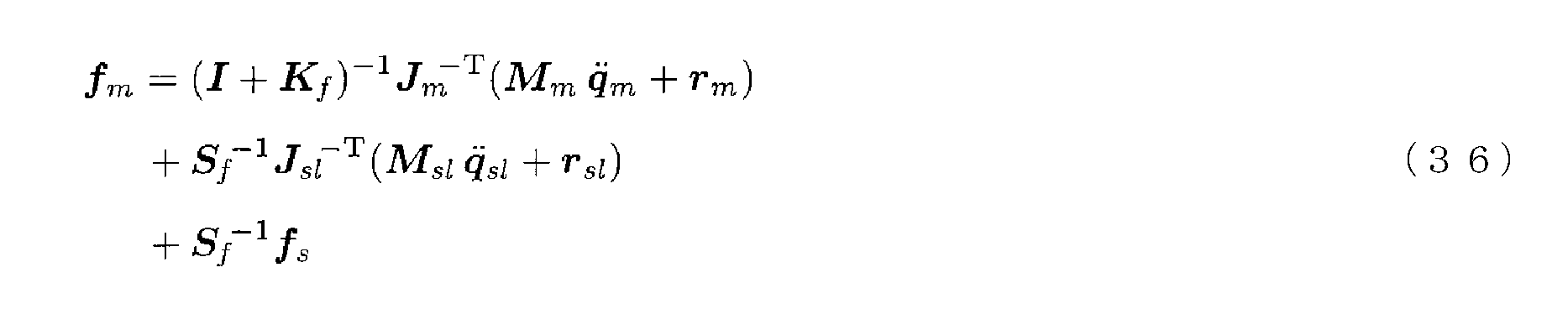
- the master operating force f m is affected by the master dynamics (the first term on the right side of Expression (36)).
- the master operating force f m is affected by the dynamics of the internal slave actuator (first term of formula (26)).
- the projectability of the force progressive servo type bilateral control according to the present invention and the force feedback type bilateral control according to the comparative example are both equations. It deviates from the exoskeleton projection represented by (31). However, the former shifts from the exoskeleton projection represented by Formula (31) to the exoskeleton projection represented by Formula (30), whereas the latter is the exoskeleton projection represented by Formula (30). Therefore, the influence on the master robot that is not a slave robot that should not be regarded as an exoskeleton but a master robot that should not be regarded as an exoskeleton is strengthened. Go. Therefore, it is expected that the former can maintain higher operability from the viewpoint of projectability than the latter.
- Equation (40) is a force order feed servo type bilateral control according to the present invention, when the slave robot receives an external force -f s, indicates that the master slave system is not affected by the dynamics of the master robot Yes. That is, the above equation is to be added to the operator U master operation force f m to the master robot, the connection from the master robot to the slave robot will automatically shut off, regardless master-slave system to the force control gain K f It shows that it becomes unilateral.
- the equation (40) is different depending on the setting of the force control gain K f when an excessive external force ⁇ f s is applied. Also shows that the dynamics inside the slave actuator can be moved significantly. This means that in the force progressive servo bilateral control according to the present invention, there is a problem of the contact stability of the slave robot that did not exist in the basic configuration. Therefore, in the power order transmission Servo bilateral control according to the present invention, in mind the stability of the slave control law (24), it is necessary to adjust the force control gain K f. However, this problem is only a problem of the stability of the force control in the slave robot alone, so the force reverse feed type bilateral control and the force feedback type bilateral control that can make the force control through the bilateral loop unstable. It is easier to solve than the contact stability problem.
- Displacement and “position” in this specification mean generalized displacement, and include translation and rotation position and orientation.
- force means generalized force and includes translational force and rotational force (torque).
- the “slave actuator” in the present invention is not limited to an actuator in a narrow sense such as an electromagnetic motor that generates a driving force, a hydraulic source, or a pneumatic source.
- the “slave actuator” is a mechanical means (driving force / load matching means) for matching impedance between the driving force and the load, such as a speed reducer, a hydraulic cylinder, or a pneumatic cylinder, or a gear, a timing belt. It means the whole actuator unit in a broad sense including a driving force transmission means such as a chain as internal dynamics.
- the “final output shaft” means any shaft that is directly connected to an adjacent link or work end, and is not limited to the rotating shaft as shown in FIG.
- the “operating force sensor” and “actual driving force sensor” in the present invention may not be a force sensor as hardware. It may be a means for estimating an operation force by an observer or the like from a sensor signal or the like.
- the “actual driving force sensor” in the present invention is attached to the final output shaft of the actuator for convenience of explanation. However, in mounting, it may be an integrated force (torque) sensor built in the actuator. .
- each bilateral control is a simple example for explanation, and a more advanced control law can be used if the control purpose is not changed.
- proportional control is used as the position control method.
- advanced control methods such as PID control and Proxy-based Sliding Mode control (see Non-Patent Document 3) that extends PID control. Can also be used.
- slave control laws (24) and (25) any control method for bringing the slave actual driving force ⁇ sa closer to the slave target actual driving force ⁇ sad can be used.
- Any control based on driving force control can be superimposed on the slave control laws (24) and (25).
- the superimposed control is applied to the slave robot that is back-drivable with reduced inertia and friction inside the slave actuator. It is beneficial.
Abstract
本発明に係るマスタスレーブシステム(1)は、スレーブロボットを駆動力制御するスレーブ駆動力(τs)を発生させるスレーブアクチュエータ(As1~3)と、スレーブアクチュエータ(As1~3)の最終出力軸に実際に作用しているスレーブ実駆動力(τsa)を計測する実駆動力センサ(Fs1~3)と、スレーブ実駆動力(τsa)の目標値であるスレーブ目標実駆動力(τsad)を操作者(U)がマスタロボットに加えたマスタ操作力(fm)に基づいて演算により求めるスレーブ目標実駆動力演算装置(3)とを備える。スレーブアクチュエータ(As1~3)は、スレーブ目標実駆動力(τsad)とスレーブ実駆動力(τsa)とに基づいてスレーブ駆動力(τs)を発生させる。
Description
本発明は、力順送型バイラテラル制御が適用されるマスタスレーブシステムに関する。
いわゆるマスタスレーブシステムは、マスタロボットとスレーブロボットとが機械的に結合し、連動する機械式マスタスレーブシステムが発端となっている。機械式マスタスレーブシステムには、操作者が直接的な操作感を得られるという長所があるが、操作者とマスタロボットおよびスレーブロボットとの幾何学的拘束から機構設計の自由が制限されるとともに、駆動源が人力であることから操作が重くならざるを得ず、また、異常時における安全確保に難があるという短所も存在する。
そこで、機械式マスタスレーブシステムの有用性は認めつつも、現在においては、マスタロボットとスレーブロボットとが電気的に相互接続され、かつ機械的には分離されて、両者が独立に動作可能な電気式マスタスレーブシステムが主流となっている。一般的に、電気式とすれば、電気的またはソフトウェア的手段による融通が利き、柔軟に機構を設計することができ、しかも、大出力アクチュエータの作業領域に操作者を入れないような、安全を確保しやすいシステムを構築することが可能となる。
このような特徴を持つ電気式マスタスレーブシステムは、遠隔操作(テレオペレーション)を主なアプリケーションとして発展してきたために、これまでは、位置や力の再現性、透明性、または通信時間遅延の改善を主眼として研究がなされてきた。以下、電気式マスタスレーブシステムにおける基本的なバイラテラル制御について俯瞰的に説明する。
まず、マスタロボットおよびスレーブロボットのダイナミクスを表現する運動方程式を、説明の便宜のため、一例として以下のように定める。


fm(t)は、時刻tにおいて操作者がマスタロボット操作端に加えるマスタ操作力、fs(t)は、同じく時刻tにおいてスレーブロボット作業端が環境(作業対象)に加えるスレーブ作業力である。また、マスタロボットおよびスレーブロボットのそれぞれについて、qm(t)、qs(t)は関節変位、τm(t)、τs(t)は関節駆動力、Mm(qm)、Ms(qs)は慣性行列、rm(q・
m,qm)、rs(q・
s,qs)は慣性以外の効果を集約した剰余項である。Jm(qm)、Js(qs)は微分運動学を表現するヤコビ行列であり、以下の関係を満たす。


xm(t)、xs(t)は、それぞれqm(t)、qs(t)に対応するマスタロボットの操作端およびスレーブロボットの作業端の作業座標系における変位である。なお、本明細書では、関数の独立変数を示す“(t)”等の記述を省略して表記することがある。
[対称型バイラテラル制御]
対称型のバイラテラル制御は、マスタ・スレーブの双方向の変位誤差サーボである。この制御では力センサが不要となるため、比較的安定な系を簡単に構成することができる。作業座標系における比例制御を用いれば、マスタロボットの制御則およびスレーブロボットの制御則は、例えば以下のようになる。


Kpは位置制御ゲインである。また、Sfはマスタロボットからスレーブロボットへの力のスケール比、Spはスレーブロボットからマスタロボットへの変位のスケール比である。
対称型のバイラテラル制御は、マスタ・スレーブの双方向の変位誤差サーボである。この制御では力センサが不要となるため、比較的安定な系を簡単に構成することができる。作業座標系における比例制御を用いれば、マスタロボットの制御則およびスレーブロボットの制御則は、例えば以下のようになる。
マスタダイナミクス(1)、スレーブダイナミクス(2)、マスタ制御則(5)およびスレーブ制御則(6)から、次式が得られる。

このように、対称型バイラテラル制御では、マスタ操作力fmにマスタダイナミクスの影響が等倍で加わるとともに、スレーブダイナミクスの影響とスレーブ作業力fsがSf
-1倍で加わる。
[力逆送型バイラテラル制御]
力逆送型のバイラテラル制御では、スレーブロボットの作業端にスレーブ作業力fsを計測する作業力センサを配置し、スレーブ作業力fsをマスタの駆動力へ「反射」させる。この場合、マスタ制御則は次式のようになる。なお、スレーブ制御則は対称型バイラテラル制御における式(6)と同じである。

力逆送型のバイラテラル制御では、スレーブロボットの作業端にスレーブ作業力fsを計測する作業力センサを配置し、スレーブ作業力fsをマスタの駆動力へ「反射」させる。この場合、マスタ制御則は次式のようになる。なお、スレーブ制御則は対称型バイラテラル制御における式(6)と同じである。
マスタダイナミクス(1)およびマスタ制御則(8)から、次式が得られる。

対称型バイラテラル制御と同様、力逆送型バイラテラル制御では、マスタ操作力fmにマスタダイナミクスの影響が等倍で加わるとともに、スレーブ作業力fsがSf
-1倍で加わる。一方、マスタ操作力fmは、スレーブダイナミクスの影響を受けない。
[力帰還型バイラテラル制御]
力帰還型のバイラテラル制御では、マスタロボットの操作端にマスタ操作力fmを計測する操作力センサを配置するとともに、スレーブロボットの作業端にスレーブ作業力fsを計測する作業力センサを配置し、マスタ側で力誤差サーボを構成する。この場合、マスタ制御則は次式のようになる。

上式は、力逆送型のマスタ制御則(8)に、右辺第1項の力誤差サーボを追加したものである。なお、Kfは力制御ゲインである。また、スレーブ制御則は対称型バイラテラル制御における式(6)と同じである。
力帰還型のバイラテラル制御では、マスタロボットの操作端にマスタ操作力fmを計測する操作力センサを配置するとともに、スレーブロボットの作業端にスレーブ作業力fsを計測する作業力センサを配置し、マスタ側で力誤差サーボを構成する。この場合、マスタ制御則は次式のようになる。
マスタダイナミクス(1)およびマスタ制御則(10)から、次式が得られる。なお、Iは単位行列である。

そして、上式において力制御ゲインKfを十分に大きくすれば、次式が得られる。

このように、力帰還型バイラテラル制御では、力制御ゲインKfを十分に大きくすることで、マスタ操作力fmへのマスタダイナミクスの影響は無視できる程小さくなり、マスタ操作力fmにはスレーブ作業力fsのみがSf
-1倍で加わる。ただし、実装上は力制御ゲインKfを大きくするにつれてバイラテラル制御の安定性が損なわれるため、マスタ操作力fmへのマスタダイナミクスの影響を完全に消すことは難しく、透明性を完全に実現することはできない。
[並列型バイラテラル制御]
宮崎らは、非特許文献1において、これまでのバイラテラル制御の直列的な接続方法を改良した並列型バイラテラル制御を提案した。並列型では、マスタロボットの操作端にマスタ操作力fmを計測する操作力センサを配置するとともに、スレーブロボットの作業端にスレーブ作業力fsを計測する作業力センサを配置して、マスタ・スレーブで並列に変位誤差サーボを構成する。この場合、制御則は例えば以下のようになる。


なお、xd(t)は、時刻tにおけるスレーブロボットの作業端およびスケールされたマスタロボットの操作端の作業座標系での目標変位である。
宮崎らは、非特許文献1において、これまでのバイラテラル制御の直列的な接続方法を改良した並列型バイラテラル制御を提案した。並列型では、マスタロボットの操作端にマスタ操作力fmを計測する操作力センサを配置するとともに、スレーブロボットの作業端にスレーブ作業力fsを計測する作業力センサを配置して、マスタ・スレーブで並列に変位誤差サーボを構成する。この場合、制御則は例えば以下のようになる。
マスタダイナミクス(1)、スレーブダイナミクス(2)、マスタ制御則(13)、スレーブ制御則(14)および目標変位演算(15)から、次式が得られる。

そして、上式において力制御ゲインKfを十分に大きくすれば、次式が得られる。

マスタ制御則とスレーブ制御則とを並列に構成することで位相遅れが減少し、バイラテラル制御の安定性が向上することが並列型バイラテラル制御の利点である。しかしながら、式(16)右辺第1項、第2項のように、並列型バイラテラル制御では、マスタ操作力fmがマスタダイナミクスおよびスレーブダイナミクスの両方の影響を受ける。さらに、式(16)右辺第3項のように、並列型バイラテラル制御では、マスタ操作力fmに元々のダイナミクスには存在しないバネ項まで付加される。力制御ゲインKfを大きくすればこれらの影響は無視できるほど小さくなるが、安定性が向上しているとはいえ、実装上は力制御ゲインKfを大きくするにつれてバイラテラル制御の安定性が損なわれるため、結局、並列型バイラテラル制御でも透明性を完全に実現することはできない。
[力順送型バイラテラル制御]
ここまで、対称型、力逆送型、力帰還型および並列型を含む、基本的なバイラテラル制御について述べたが、これらをはじめとする従来のバイラテラル制御は、以下の問題1~10を有していた。
[問題1]・・・力逆送型、力帰還型および並列型に共通する問題
制御にスレーブ作業力fsの情報を必要とするため、スレーブロボットに作業力センサを実装できないシステムには適用が困難である。
[問題2]・・・対称型および力逆送型に共通する問題
マスタロボットの変位誤差によってシステムが駆動される制御であるため、人力で簡単にマスタロボットの変位誤差を発生することができるように、すわなち、高いバックドライバビリティが保たれるようにマスタロボットの慣性および摩擦を極力小さくしておかなければならない。このため、マスタロボットを華奢で低減速比の非力な機構とすることが必須である。
[問題3]・・・対称型、力逆送型、力帰還型および並列型に共通する問題
マスタダイナミクスがマスタ操作力fmに影響を及ぼす制御であるため、操作性向上のためには、やはりマスタロボットの慣性および摩擦を極力小さくしておかなければならない。このため、マスタロボットを華奢で低減速比な非力な機構とすることが望まれる。
[問題4]・・・力逆送型および力帰還型に共通する問題
透明性を規範とする、すなわちスレーブダイナミクスがマスタ操作力fmに影響を及ぼさない制御であるため、スレーブダイナミクスを感じることによる操作者のスキル向上、ひいては、スレーブロボット操作の効率化および最適化を期待できない。
[問題5]・・・力帰還型および並列型に共通する問題
透明性を規範とする制御であるにもかかわらず、透明性と安定性はトレードオフの関係にあるため、必要な安定性を確保すると、透明性が実現されなくなる可能性がある。
[問題6]・・・力逆送型、力帰還型および並列型に共通する問題
スレーブロボットに配置した作業力センサが硬い環境へ接触すると、システムが不安定化する危険(スレーブロボットの接触安定性の問題)がある。これを防ぐためには、力制御ゲインKfを十分に下げておくか、あるいは、スレーブロボットと環境とが接触していないときと接触しているときとで制御則を切り替えることが考えられるが、前者は操作性および透明性を低下させ、後者は実装を煩雑にする。
[問題7]・・・対称型、力逆送型、力帰還型および並列型に共通する問題
スレーブロボットとマスタロボットが常に双方向に接続されているため、操作者がマスタロボットに対して何もしなくてもスレーブロボットに加えられる外力-fsのみによってシステムに不安定な挙動が励起される危険がある。
[問題8]・・・対称型、力逆送型、力帰還型および並列型に共通する問題
スレーブロボットへの指令値が位置であり、位置制御によってスレーブダイナミクスをキャンセルしなければならないため、制御系への負荷が大きい。さらに、位置制御ベースの制御則では、必ずしも他の制御則を重畳することができるとは限らない。
[問題9]・・・力逆送型、力帰還型および並列型に共通する問題
スレーブロボットの位置制御においてスレーブアクチュエータの出力が不足してスレーブ駆動力τsが飽和すると、マスタ変位とスレーブ変位との誤差が増大し、操作性が低下する可能性がある。
[問題10]・・・対称型、力逆送型、力帰還型および並列型に共通する問題
スレーブロボットに作業座標系での位置制御を適用すると特異点問題が生じ、スレーブロボットの姿勢が特異点近傍となったときに制御が破綻する可能性がある。
これらの問題をエレガントに解決し得る新たなバイラテラル制御として、本発明者は、特許文献1において「力順送型バイラテラル制御」の基本構成を提案した。力順送型では、マスタロボットの操作端にマスタ操作力fmを計測する操作力センサを配置し、計測したマスタ操作力fmをスレーブ駆動力τsへ「投射」する。力順送型バイラテラル制御におけるマスタ制御則およびスレーブ制御則は、例えば以下のようになる。


スレーブダイナミクス(2)およびスレーブ制御則(19)から、次式が得られる。

このように、力順送型バイラテラル制御では、マスタ操作力fmにスレーブダイナミクスの影響とスレーブ作業力fsがSf
-1倍で加わる。すなわち、力順送型バイラテラル制御とは、スレーブロボットが環境(作業対象)に加えるスレーブ作業力fsを計測するのではなく、操作者がマスタロボットに加えるマスタ操作力fmを計測することで、マスタからスレーブへは力情報を順送し、スレーブからマスタへは変位情報を逆送する手法である。
力順送型バイラテラル制御は、以下の特徴1~10を有している。
[特徴1]
スレーブ作業力fsの情報を必要としないため、スレーブロボットに作業力センサを実装できないシステムにも適用することができる。
[特徴2]
マスタロボットの変位誤差ではなく、操作者がマスタロボットに加えるマスタ操作力fmによってシステムが駆動されるため、マスタロボットにバックドライバビリティが必要とされず、その結果、マスタロボットを人力に対して堅牢で、高精度で、かつ強力な機構とすることができる。
[特徴3]
マスタダイナミクスがマスタ操作力fmに影響を及ぼさない制御であるため、操作性向上のためにマスタロボットの慣性および摩擦を小さくしておく必要がない。このため、特徴2とは別の理由で、やはりマスタロボットを人力に対して堅牢で、高精度で、かつ強力な機構とすることができる。
[特徴4]
透明性を規範としない、すなわちスレーブダイナミクスがマスタ操作力fmに影響を及ぼす制御であるため、スレーブダイナミクスを感じることによる操作者のスキル向上、ひいては、スレーブロボット操作の効率化および最適化が期待できる。
[特徴5]
透明性ではなく、本発明者が特許文献2において定義した「投射性」を規範とする制御であり、安定性とのトレードオフではなく、安定性とは独立に、必要とされる精度で投射性を実現することができる。
[特徴6]
スレーブロボットからマスタロボットに、力情報ではなく変位情報が逆送される制御であるため、スレーブロボットの接触安定性の問題は存在しない。
[特徴7]
操作者がマスタロボットにマスタ操作力fmを加えなければ、マスタロボットからスレーブロボットへの接続は遮断される(バイラテラルでなくなり、ユニラテラルとなる)ので、スレーブロボットに加えられる外力-fsのみによってシステムに不安定な挙動が励起される危険はない。
[特徴8]
スレーブロボットへの指令値が位置ではなく駆動力(力とトルク)なので、スレーブ制御則の実装が容易であり、制御系への負荷が小さい。また、駆動力制御ベースの制御なので、スレーブ制御則に駆動力制御ベースのあらゆる制御を重畳することができる。
[特徴9]
スレーブロボットの駆動力制御においてスレーブアクチュエータの出力が不足してスレーブ駆動力τsが飽和した場合でも、マスタロボットを人力に対して強力な機構としておけば、マスタロボットの位置制御においてマスタアクチュエータの出力が飽和する可能性は低いので、マスタ変位とスレーブ変位とを十分な精度で一致させることができ、操作性は低下しない。
[特徴10]
スレーブロボットが位置制御ではなく駆動力制御されるので、作業座標系での制御を適用しても特異点問題が生じず、スレーブロボットの姿勢が特異点近傍となっても制御が破綻することはない。
宮崎,萩原,"バイラテラル・マスタ・スレーブ・マニピュレータの並列型制御方式",日本ロボット学会誌,vol.7,no.5,pp.446-452,1989.
吉灘,"大形バイラテラルマニピュレータの研究",東京工業大学博士学位論文,2012.
Ryo Kikuuwe, Satoshi Yasukouchi, Hideo Fujimoto, and Motoji Yamamoto," Proxy-Based Sliding Mode Control: A Safer Extension of PID Position Control," IEEE Transactions on Robotics, Vol.26, No.4, pp.670-683, 2010.
以上のように、本発明者が特許文献1において提案した力順送型バイラテラル制御は、従来のバイラテラル制御にはない多くの利点を有しているが、その一方で解決を要する以下の問題A~Eを有している。
[問題A]
マスタロボットの操作力センサが硬い環境へ接触したり、該操作力センサにイレギュラーな衝撃が加わったりすると、これらをきっかけとしてシステムに不安定な挙動が励起される危険(マスタロボットの接触安定性の問題)がある。
[問題B]
バイラテラル制御の安定性が考慮されていないので、安定性を確保するために、スレーブロボットからマスタロボットへの変位のスケール比Sp、およびマスタロボットからスレーブロボットへの力のスケール比Sfを十分に大きくできない可能性がある。
[問題C]
操作者たる人間の感覚特性と、操作力センサおよび変位センサの実装における特性とが考慮されていないので、必ずしも人間の感覚特性に適合した制御設計になっているとはいえない。
[問題D]
作業座標系での制御において、マスタロボットの特異点およびその近傍において操作性が極端に低下する可能性がある。
[問題E]
スレーブロボットを構成するリンク機構の動的挙動(ダイナミクス)、および環境(作業対象)の動的挙動(ダイナミクス)を操作者が適切に感じるためには、スレーブロボットが高いバックドライバビリティを有している必要がある。
なお、スレーブロボットがバックドライバビリティを有していなくても、力順送型バイラテラル制御が破綻することはなく、バックドライバビリティが存在しないことをスレーブダイナミクスの一部として操作者が感じるだけである。しかしながら、スレーブロボットが高いバックドライバビリティを有していない場合、より詳しくは、バックドライバビリティが主にスレーブロボットの関節を構成するスレーブアクチュエータの内部の機構(減速機等)で失われた場合は、スレーブアクチュエータの外部に存在するスレーブロボットのダイナミクス、すなわち、リンク機構としてのダイナミクスや環境(作業対象)のダイナミクスを操作者が感じることは困難となる。そして、その結果、力順送型バイラテラル制御の上記特徴4が、部分的に、もしくは全面的に失われるという好ましくない結果を招く。
上記問題A~Eのうち、問題A~Cについては、本発明者が特許文献3において提案した手法により解決することができる。また、問題Dについては、本発明者が特許文献2において提案した手法により解決することができる。しかしながら、問題Eについては、未だ好適な解決手法は提案されていない。
本発明はこのような事情に鑑みてなされたものであり、機構的構造によりスレーブロボットのバックドライバビリティが低いマスタスレーブシステムにおいて、スレーブロボットのバックドライバビリティを高くすることのできるマスタスレーブシステムを提供することを課題とする。
本発明者が特許文献1で提案した基本的な力順送型バイラテラル制御は、スレーブロボットが環境に加えるスレーブ作業力を計測する作業力センサを不要としたことを特徴の一つとしている。このような構成としたのは、少なからぬマスタスレーブシステムにおいては、スレーブロボットの作業端に作業力センサを実装することが困難であることによる。
しかしながら、全てのマスタスレーブシステムのスレーブロボットに力センサを一切実装できないというわけではなく、以下の理由(1)、(2)により、スレーブロボットの作業端ではない箇所に、多軸力センサではなく一軸力センサを実装することは必ずしも困難ではない。
(1)スレーブロボットの作業端が硬い環境へ接触する際、作業端はその衝撃を直接的に受けるが、作業端以外の箇所は、たとえその箇所と作業端が剛体リンクで繋がっていたとしても、実際には必ず存在するリンクの粘弾性によって、衝撃は緩和される。
(2)作業端に実装する多軸力センサは、その機構の複雑さのために繊細で高価だが、一軸力センサは、機構が単純であり、一般に多軸力センサよりも堅牢で安価である。現に、いわゆるロードセルやトルクセンサとして、劣悪環境においても使用できる一軸力センサが市販されている。
(1)スレーブロボットの作業端が硬い環境へ接触する際、作業端はその衝撃を直接的に受けるが、作業端以外の箇所は、たとえその箇所と作業端が剛体リンクで繋がっていたとしても、実際には必ず存在するリンクの粘弾性によって、衝撃は緩和される。
(2)作業端に実装する多軸力センサは、その機構の複雑さのために繊細で高価だが、一軸力センサは、機構が単純であり、一般に多軸力センサよりも堅牢で安価である。現に、いわゆるロードセルやトルクセンサとして、劣悪環境においても使用できる一軸力センサが市販されている。
本発明者は、鋭意検討した結果発見した上記知見に基づき、上記課題を解決することができるマスタスレーブシステムを完成させた。
すなわち、本発明に係るマスタスレーブシステムは、
操作者によって操られるアドミッタンス型の力覚提示装置であるマスタロボットと、前記マスタロボットに少なくとも電気的に接続され、かつ前記マスタロボットから少なくとも体幹以外が機械的に独立して動作するスレーブロボットとからなる、バイラテラル制御されるマスタスレーブシステムであって、
前記マスタロボットを位置制御するマスタ駆動力を発生させる少なくとも一つのマスタアクチュエータと、前記スレーブロボットを駆動力制御するスレーブ駆動力を発生させる少なくとも一つのスレーブアクチュエータと、前記マスタロボットにおけるマスタ変位を計測する少なくとも一つのマスタ変位センサと、前記スレーブロボットにおけるスレーブ変位を計測する少なくとも一つのスレーブ変位センサと、前記操作者が前記マスタロボットに加えるマスタ操作力を計測する少なくとも一つの操作力センサと、前記スレーブアクチュエータの最終出力軸に実際に作用しているスレーブ実駆動力を計測する少なくとも一つの実駆動力センサと、前記マスタ変位の目標値であるマスタ目標変位を前記スレーブ変位に基づいて演算により求めるマスタ目標変位演算装置と、前記スレーブ実駆動力の目標値であるスレーブ目標実駆動力を前記マスタ操作力に基づいて演算により求めるスレーブ目標実駆動力演算装置とを備え、
前記マスタアクチュエータが前記マスタ目標変位と前記マスタ変位とに基づいて前記マスタ駆動力を発生させる一方、前記スレーブアクチュエータが前記スレーブ目標実駆動力と前記スレーブ実駆動力とに基づいて前記スレーブ駆動力を発生させることで、(1)前記スレーブロボットが環境に加えるスレーブ作業力を前記バイラテラル制御のために計測するスレーブロボット作業端の作業力センサを不要とし、(2)前記操作者に前記マスタロボットのマスタダイナミクスと前記スレーブアクチュエータの内部のダイナミクスとを感じさせることなく、前記スレーブアクチュエータの外部のダイナミクスを感じさせるようにしたことを特徴としている。
上記マスタスレーブシステムの具体的一例としては、前記スレーブアクチュエータが、前記スレーブ駆動力を発生させる駆動源と、前記駆動源の出力軸に設けられた駆動力・負荷整合手段もしくは駆動力伝達手段とを含み、前記実駆動力センサが、前記最終出力軸である前記駆動力・負荷整合手段もしくは前記駆動力伝達手段の出力軸に設けられた、一軸の前記スレーブ実駆動力を計測し得る一軸力センサである構成が考えられる。
本発明によれば、機構的構造によりスレーブロボットのバックドライバビリティが低いマスタスレーブシステムにおいて、スレーブロボットのバックドライバビリティを高くすることのできるマスタスレーブシステムを提供することができる。
以下、図面を参照しながら本発明の実施例について説明する。
[実施例]
図1に示すように、本発明の実施例に係る力順送型マスタスレーブシステム(正確には、力順送型バイラテラル制御が適用されたマスタスレーブシステム)1は、体幹Bの異なる位置に設けられるとともに、以下の要領で互いに電気的に接続されたマスタアームMを含むマスタロボットとスレーブアームSを含むスレーブロボットとからなる。この力順送型マスタスレーブシステム1において、マスタアームMは、操作者Uによって操られるアドミッタンス型の力覚提示装置である。
図1に示すように、本発明の実施例に係る力順送型マスタスレーブシステム(正確には、力順送型バイラテラル制御が適用されたマスタスレーブシステム)1は、体幹Bの異なる位置に設けられるとともに、以下の要領で互いに電気的に接続されたマスタアームMを含むマスタロボットとスレーブアームSを含むスレーブロボットとからなる。この力順送型マスタスレーブシステム1において、マスタアームMは、操作者Uによって操られるアドミッタンス型の力覚提示装置である。
マスタアームMとスレーブアームSは、それぞれ一端側に、操作端となるグリップGと作業端dを有するとともに、他端側が体幹Bの異なる位置に備えられている。また、マスタアームMとスレーブアームSは、それぞれ、2本のリンクを有するとともに、グリップGまたは作業端dに接続される一端、体幹Bに接続される他端、およびリンク同士の接続部分に各1つの関節(一例として、回転関節)を有している。したがって、本実施例では、マスタアームMとスレーブアームSは、それぞれ3自由度を有している。
マスタアームMの各関節には、マスタ変位センサPm1~3およびマスタアクチュエータAm1~3が備えられ、スレーブアームSの各関節には、スレーブ変位センサPs1~3、スレーブアクチュエータAs1~3および実駆動力センサFs1~3が備えられている。また、グリップGには、操作力センサFmが備えられている。さらに、図1に示すように、この力順送型マスタスレーブシステム1には、位置制御系PCm、マスタ目標変位演算装置2、駆動力制御系FCsおよびスレーブ目標実駆動力演算装置3が備えられている。
なお、本明細書では、マスタアームM、マスタ変位センサPm1~3、マスタアクチュエータAm1~3、操作力センサFm(グリップG)、および位置制御系PCmがマスタロボットに含まれ、スレーブアームS、スレーブ変位センサPs1~3、スレーブアクチュエータAs1~3、実駆動力センサFs1~3、および駆動力制御系FCsがスレーブロボットに含まれるものとする。また、本明細書では、位置制御系PCmとマスタアクチュエータAm1~3とを切り分けることなく、位置制御系PCmが一体化された「マスタアクチュエータ」として取り扱ったり、駆動力制御系FCsとスレーブアクチュエータAs1~3とを切り分けることなく、駆動力制御系FCsが一体化された「スレーブアクチュエータ」として取り扱ったりすることがある。
操作力センサFmはマスタアームMに設けられ、操作者Uからのマスタ操作力fmを計測する。マスタ変位センサPm1~3はマスタアームMの各関節に設けられ、マスタ変位qmおよびxmを計測する。スレーブ変位センサPs1~3はスレーブアームSの各関節に設けられ、スレーブ変位qsおよびxsを計測する。また、実駆動力センサFs1~3はスレーブアームSの各関節に設けられ、後述するスレーブ実駆動力τsaを計測する。
マスタ目標変位演算装置2は、計測されたスレーブ変位qsおよびxsに基づきマスタ変位qmおよびxmの目標値であるマスタ目標変位を演算により求める。また、スレーブ目標実駆動力演算装置3は、計測されたマスタ操作力fmに基づきスレーブ実駆動力τsaの目標値であるスレーブ目標実駆動力τsadを演算により求める。
スレーブアクチュエータAs1~3は、スレーブアームSの各関節に設けられ、スレーブ目標実駆動力τsadおよびスレーブ実駆動力τsaに基づき駆動力制御系FCsを通じてスレーブ駆動力τsを発生させ、これによりスレーブアームSが駆動力制御される。一方、マスタアクチュエータAm1~3は、マスタアームMの各関節に設けられ、マスタ変位qmおよびxmとマスタ目標変位とに基づきマスタ駆動力τmを発生させ、これによりマスタアームMが位置制御される。より詳しくは、マスタアクチュエータAm1~3は、マスタ変位センサPm1~3からの信号とマスタ目標変位演算装置2からの信号との偏差が0になるように位置制御系PCmを通じてマスタ駆動力τmを発生させる。
このように、力順送型マスタスレーブシステム1では、スレーブ駆動力τsを発生させるスレーブアクチュエータAs1~3によってスレーブアームSが駆動力制御される一方、マスタ駆動力τmを発生させるマスタアクチュエータAm1~3によってマスタアームMが位置制御される。
図2は、この構成を制御ブロック図で表現したものである。図2のマスタロボットには、マスタアームM、マスタ変位センサPm1~3、マスタアクチュエータAm1~3、操作力センサFm(グリップG)、および位置制御系PCmが含まれる。また、スレーブロボットには、スレーブアームS、スレーブ変位センサPs1~3、スレーブアクチュエータAs1~3、実駆動力センサFs1~3、および駆動力制御系FCsが含まれる。同図から明らかなように、本実施例に係る力順送型マスタスレーブシステム1では、操作者Uがマスタロボットに加えるマスタ操作力fmを計測することで、マスタからスレーブへは力情報を順送し、スレーブからマスタへは変位情報を逆送する。
図4は、n自由度(ただし、nは正整数)を有するスレーブアームSのi-1番目(ただし、i=1,2,・・・,n)のリンク10と該リンク10よりも作業端d側に位置するi番目のリンク11との間に設けられたi番目の関節の模式図である。同図に示すように、i番目の関節のスレーブアクチュエータAsiは、スレーブ駆動力τsを発生させる駆動源12と、その出力軸14に設けられた減速機13とを含んでいる。なお、図示されていないが、減速機13の基部は、駆動源12の基部と同様に、リンク10に固定されているものとする。そして、減速機13の出力軸、すなわちスレーブアクチュエータAsiの最終出力軸15は、リンク10とリンク11とで構成されたリンク機構の関節軸16に直結されている。
この場合、式(2)で表されるスレーブロボットのダイナミクスは、減速機13を含むスレーブアクチュエータAsi内部のダイナミクス(21)と、スレーブアクチュエータAsi外部のダイナミクス(22)とに分割される。


qsa(t)は、i-1番目のリンク10を基準としたスレーブアクチュエータAsiの変位(=出力軸14の変位)、qsl(t)は、同じくi-1番目のリンク10を基準とした最終出力軸15の変位(=i番目のリンク11の関節軸16の変位)、Msaは、スレーブアクチュエータAsiの慣性行列、Mslは、スレーブアームSのリンク機構の慣性行列、rsaおよびrslは、慣性以外の効果を集約した剰余項である。また、JsaおよびJslはヤコビ行列であり、Jsと以下の関係がある。

なお、剰余項rsaは、独立変数を明示するとrsa(q・
sa,qsa,q・
sl,qsl)となり、剰余項rslは、独立変数を明示するとrsl(q・
sl,qsl)となる。ただし、スレーブアクチュエータAsiの構成によっては、剰余項rsaおよびrslは、上記独立変数の一部のみに依存し、他には依存しないことがある点に注意が必要である。
スレーブアクチュエータAsiの最終出力軸15とリンク機構の関節軸16とが直結された図4に示す構成においては、スレーブアクチュエータAsi内部のダイナミクスと外部のダイナミクスは、最終出力軸15の駆動力によって結合される。この駆動力を、本発明ではスレーブ実駆動力τsaと呼ぶことにする。スレーブ駆動力τsが、スレーブアクチュエータAsi内部の駆動源12が発生する駆動力であるのに対し、スレーブ実駆動力τsaは、スレーブ駆動力τsからスレーブアクチュエータAsi内部の減速機13のダイナミクスによる損失を差し引いた、スレーブアクチュエータAsi外部に実際に取り出される駆動力である。
スレーブ実駆動力τsaは、スレーブアクチュエータAsiの最終出力軸15に実駆動力センサFsiとしての一軸力センサを配置することで、精度良く計測することができる。図1に示すように、スレーブアームSが3自由度を有している場合、3つの関節のそれぞれに一軸力センサが配置される。言い換えると、本実施例に係る力順送型マスタスレーブシステム1では、関節の数と同数の一軸力センサからなるセンサ群がスレーブアームSに配置される。
本実施例に係る力順送型マスタスレーブシステム1では、例えばスレーブ制御則(24)、(25)を用いる。これは、式(19)のスレーブ制御則に実駆動力誤差サーボを追加したものである。


一方、マスタ制御則は式(18)と同じである。以下、本明細書では、スレーブ制御則(24)、(25)とマスタ制御則(18)とによる力順送型バイラテラル制御を、特に「力順送サーボ型バイラテラル制御」と呼ぶ。
スレーブアクチュエータAsi内部のダイナミクス(21)、スレーブアクチュエータAsi外部のダイナミクス(22)、およびスレーブ制御則(24)、(25)から、次式が得られる。

そして、式(26)において力制御ゲインKfを十分大きくすれば、次式が得られる。

式(27)は、実駆動力センサFsiを設けることによって、操作者Uに、スレーブアクチュエータAsi内部のダイナミクス(21)を感じさせることなく、スレーブアクチュエータAsi外部のダイナミクス(22)のみをSf
-1倍で感じさせることができることを示している。
なお、式(26)において力制御ゲインKf=0とすれば、次式が得られる。

式(28)は、本発明者が特許文献1において提案した力順送型バイラテラル制御の基本構成における式(20)と同じである。すなわち、式(24)および(25)からも理解されるように、力順送サーボ型バイラテラル制御は、力制御ゲインKf=0とすれば、力順送型バイラテラル制御の基本構成に帰着する。
力制御ゲインKfを大きくするにつれてバイラテラル制御の安定性は損なわれる。このため、実際には、マスタ操作力fmにおけるスレーブアクチュエータAsi内部のダイナミクス(21)の影響を、式(27)のように完全に消すことは難しい。しかしながら、スレーブアクチュエータAsi内部のダイナミクス(21)の影響を完全に消すことはできなくても、影響を小さくすることができれば有益である。つまり、力順送サーボ型バイラテラル制御では、安定性を確保できる範囲内で力制御ゲインKfをできるだけ大きくすることで、スレーブアクチュエータAsi内部の慣性および摩擦を低減することができる。言い換えると、力順送サーボ型バイラテラル制御では、安定性を確保できる範囲内で力制御ゲインKfをできるだけ大きくすることで、バックドライバブルではないスレーブロボットを、バックドライバブルなものにすることができる。
ここで、特許文献2において、本発明者は、理想的な投射性が実現されている状態、すなわち「外骨格投射」を以下のように定義した。


力順送サーボ型バイラテラル制御では、式(30)を次式のように修正すれば、スレーブアクチュエータAsi内部のダイナミクスをキャンセルして操作性の向上を図ることができるとの考えに基づき、上記スレーブ制御則(24)、(25)を使用している。

そして、力順送サーボ型バイラテラル制御では、スレーブ制御則(24)、(25)とスレーブアクチュエータAsi内部のダイナミクス(21)とから得た次式の投射性が実現される。

力制御ゲインKf→∞とすると、式(32)は式(31)に等しくなる。一方、力制御ゲインKf=0とすると、式(32)は式(30)に等しくなる。つまり、力順送サーボ型バイラテラル制御によれば、力制御ゲインKfを0と∞の間で調節することで、式(30)で表された外骨格投射と式(31)で表された外骨格投射の中間の投射性を実現することができる。
本実施例に係る力順送型(力順送サーボ型)マスタスレーブシステム1のスレーブ側の構成を整理すると、以下の通りとなる。
スレーブ目標実駆動力演算装置は、図2および式(25)に示すように、スレーブ実駆動力τsaの目標値であるスレーブ目標実駆動力τsadをマスタ操作力fmに基づいて演算により求める。
スレーブロボットの駆動力制御系は、図3および式(24)に示すように、スレーブ実駆動力τsaとスレーブ目標実駆動力τsadとに基づいてスレーブアクチュエータにスレーブ駆動力τsを発生させる。
実駆動力センサは、図3に示すように、スレーブアクチュエータ内部のダイナミクス(式(21)に相当)とスレーブアクチュエータ外部のダイナミクス(式(22)に相当)とを結合するスレーブ実駆動力τsaを測定する。
スレーブ目標実駆動力演算装置は、図2および式(25)に示すように、スレーブ実駆動力τsaの目標値であるスレーブ目標実駆動力τsadをマスタ操作力fmに基づいて演算により求める。
スレーブロボットの駆動力制御系は、図3および式(24)に示すように、スレーブ実駆動力τsaとスレーブ目標実駆動力τsadとに基づいてスレーブアクチュエータにスレーブ駆動力τsを発生させる。
実駆動力センサは、図3に示すように、スレーブアクチュエータ内部のダイナミクス(式(21)に相当)とスレーブアクチュエータ外部のダイナミクス(式(22)に相当)とを結合するスレーブ実駆動力τsaを測定する。
[比較例1]
続いて、作業力センサで測定したスレーブ作業力fsの代わりに実駆動力センサで測定したスレーブ実駆動力τsaをマスタ駆動力へ反射させる、比較例1に係る力逆送型バイラテラル制御と本発明に係る力順送サーボ型バイラテラル制御とを比較する。
続いて、作業力センサで測定したスレーブ作業力fsの代わりに実駆動力センサで測定したスレーブ実駆動力τsaをマスタ駆動力へ反射させる、比較例1に係る力逆送型バイラテラル制御と本発明に係る力順送サーボ型バイラテラル制御とを比較する。
比較例1に係る力逆送型バイラテラル制御では、マスタ制御則は次式の通りとなる。なお、スレーブ制御則は式(6)と同じである。

マスタダイナミクス(1)、スレーブアクチュエータ外部のダイナミクス(22)、およびマスタ制御則(33)から、次式が得られる。

本比較例に係る力逆送型バイラテラル制御でも、マスタ操作力fmにマスタダイナミクスの影響が等倍で加わるとともに、スレーブ作業力fsがSf
-1倍で加わる。そして、マスタ操作力fmには、さらにスレーブダイナミクスの影響もSf
-1倍で加わる。
本比較例に係る力逆送型バイラテラル制御では、本発明者が特許文献1において提案した力順送型バイラテラル制御の基本構成と同様、操作者Uがスレーブダイナミクスを感じることができるので、上記特徴4の作用効果が得られる。これに関し、非特許文献2には、本比較例に係る力逆送型バイラテラル制御に類似した手法を用いてスレーブダイナミクスの慣性力を操作者Uに提示することで、パワー増幅マスタスレーブシステムの操作性が向上したことが指摘されている。
しかしながら、本比較例に係る力逆送型バイラテラル制御では、上記の通り、操作者Uは依然としてマスタダイナミクスの影響も感じることになる。このため、本比較例に係る力逆送型バイラテラル制御では、従来のバイラテラル制御が抱えていた問題1および4は解決されるが、問題2、3、7~10は解決されない。また、本比較例に係る力逆送型バイラテラル制御は、マスタ制御則(33)でヤコビ行列Jsl
-Tが使われているため、スレーブロボットの姿勢が特異点近傍となったときに、マスタ制御則(33)が駆動力制御であるにもかかわらず破綻する可能性がある。
[比較例2]
次に、作業力センサで測定したスレーブ作業力fsの代わりに実駆動力センサで測定したスレーブ実駆動力τsaをマスタ駆動力へ反射させつつ、操作力センサで測定したマスタ操作力fmによってマスタ側で力誤差サーボを構成した、比較例2に係る力帰還型バイラテラル制御と本発明に係る力順送サーボ型バイラテラル制御とを比較する。
次に、作業力センサで測定したスレーブ作業力fsの代わりに実駆動力センサで測定したスレーブ実駆動力τsaをマスタ駆動力へ反射させつつ、操作力センサで測定したマスタ操作力fmによってマスタ側で力誤差サーボを構成した、比較例2に係る力帰還型バイラテラル制御と本発明に係る力順送サーボ型バイラテラル制御とを比較する。
比較例2に係る力帰還型バイラテラル制御では、マスタ制御則は次式の通りとなる。なお、スレーブ制御則は式(6)と同じである。

マスタダイナミクス(1)、スレーブアクチュエータ外部のダイナミクス(22)、およびマスタ制御則(35)から、次式が得られる。
そして、上式において力制御ゲインKfを十分に大きくすれば、次式が得られる。

式(37)は、本発明に係る力順送サーボ型バイラテラル制御における式(27)と全く同じである。したがって、本比較例に係る力帰還型バイラテラル制御によれば、本発明に係る力順送サーボ型バイラテラル制御と同様に、理想的には外骨格投射を実現することができる。
しかしながら、力制御ゲインKfを大きくするとバイラテラル制御の安定性は損なわれる。このため、実際には、力制御ゲインKfを∞にすることはできない。力制御ゲインKfが∞ではない場合、本比較例に係る力帰還型バイラテラル制御では、マスタ操作力fmがマスタダイナミクス(式(36)の右辺第1項)の影響を受けるのに対し、本発明に係る力順送サーボ型バイラテラル制御では、マスタ操作力fmがスレーブアクチュエータ内部のダイナミクス(式(26)の右辺第1項)の影響を受ける。
このように、力制御ゲインKfを∞から小さくしていくと、本発明に係る力順送サーボ型バイラテラル制御および本比較例に係る力帰還型バイラテラル制御の投射性は、いずれも式(31)で表された外骨格投射から外れていく。ただし、前者が、式(31)で表された外骨格投射から式(30)で表された外骨格投射へ移っていくのに対し、後者は、式(30)で表された外骨格投射からも式(31)で表された外骨格投射からも外れ、外骨格と見做すべきスレーブロボットでなく、外骨格と見做すべきでない操作装置にすぎないマスタロボットへの影響を強めていく。そのため、後者よりも前者の方が、投射性の観点からは操作性を高く維持できることが期待される。
結局、本比較例に係る力帰還型バイラテラル制御では、従来のバイラテラル制御が抱えていた問題1および4は解決されるが、問題3、5、7~10は解決されない。また、本比較例に係る力帰還型バイラテラル制御は、マスタ制御則(35)でヤコビ行列Jsl
-Tが使われているため、スレーブロボットの姿勢が特異点近傍となったときに、マスタ制御則(35)が駆動力制御であるにもかかわらず破綻する可能性がある。
[操作者がマスタロボットを操作しない場合の比較]
操作者Uがマスタロボットを操作しない場合、すなわちマスタ操作力fm=0の場合、マスタスレーブシステムは外力-fsのみによって駆動される。式(34)より、比較例1に係る力逆送型バイラテラル制御では、外力-fsは次式で表される。

また、式(36)より、比較例2に係る力帰還型バイラテラル制御では、外力-fsは次式で表される。

式(38)および式(39)は、比較例1および比較例2に係るバイラテラル制御では、スレーブ実駆動力τsaを利用しない場合と同様に、スレーブロボットが外力-fsを受けると操作装置にすぎないマスタロボットのダイナミクスの影響下でマスタスレーブシステムが動作することを示している。
操作者Uがマスタロボットを操作しない場合、すなわちマスタ操作力fm=0の場合、マスタスレーブシステムは外力-fsのみによって駆動される。式(34)より、比較例1に係る力逆送型バイラテラル制御では、外力-fsは次式で表される。
一方、本発明に係る力順送サーボ型バイラテラル制御では、外力-fsは次式で表される。
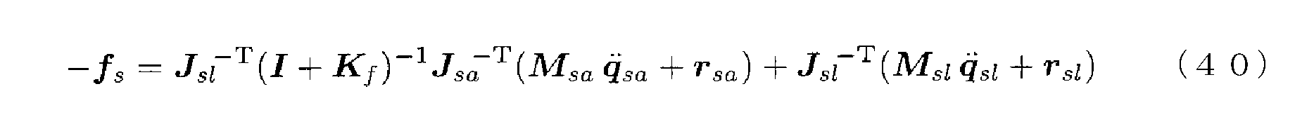
式(40)は、本発明に係る力順送サーボ型バイラテラル制御では、スレーブロボットが外力-fsを受けたときに、マスタスレーブシステムがマスタロボットのダイナミクスの影響を受けないことを示している。すなわち、上式は、操作者Uがマスタロボットにマスタ操作力fmを加えなければ、マスタロボットからスレーブロボットへの接続は自動的に遮断され、マスタスレーブシステムが力制御ゲインKfに関係なくユニラテラルとなることを示している。
なお、式(40)は、スレーブ実駆動力τsaを利用しない力順送型バイラテラル制御の基本構成とは異なり、過大な外力-fsが加えられると、力制御ゲインKfの設定によってはスレーブアクチュエータ内部のダイナミクスが大きく動かされる可能性があることも示している。これは、本発明に係る力順送サーボ型バイラテラル制御では、基本構成では存在しなかったスレーブロボットの接触安定性の問題が存在することを意味する。このため、本発明に係る力順送サーボ型バイラテラル制御においては、スレーブ制御則(24)の安定性に留意して、力制御ゲインKfを調節する必要がある。ただし、この問題は、スレーブロボット単体での力制御の安定性の問題にすぎないので、バイラテラルループを介した力制御が不安定となり得る力逆送型バイラテラル制御および力帰還型バイラテラル制御における接触安定性の問題よりも解決は容易である。
[注意事項]
本明細書では、便宜上、マスタロボット、スレーブロボットという表現を使用したが、必ずしも本発明はいわゆるロボットらしいロボットへの適用のみに限られない。マスタスレーブシステムおよびバイラテラル制御には広範な応用が期待されており、あらゆる電気式マスタスレーブシステムに本発明は適用することができる。例えばX-by-Wireシステム(バイワイヤシステム)と呼ばれるものは、全て電気式マスタスレーブシステムである。したがって、マスタスレーブロボットシステムのみならず、自動車、航空機、船舶、その他あらゆる操縦型機械のX-by-Wireシステムにおいてバイラテラル制御を使用する場合に、本発明をそのまま適用することができる。
本明細書では、便宜上、マスタロボット、スレーブロボットという表現を使用したが、必ずしも本発明はいわゆるロボットらしいロボットへの適用のみに限られない。マスタスレーブシステムおよびバイラテラル制御には広範な応用が期待されており、あらゆる電気式マスタスレーブシステムに本発明は適用することができる。例えばX-by-Wireシステム(バイワイヤシステム)と呼ばれるものは、全て電気式マスタスレーブシステムである。したがって、マスタスレーブロボットシステムのみならず、自動車、航空機、船舶、その他あらゆる操縦型機械のX-by-Wireシステムにおいてバイラテラル制御を使用する場合に、本発明をそのまま適用することができる。
本明細書中の「変位」および「位置」は一般化変位を意味し、並進・回転の位置姿勢を含むものとする。同じく「力」は一般化力を意味し、並進力・回転力(トルク)を含むものとする。
本発明における「スレーブアクチュエータ」は、駆動力を発生する電磁モータ、油圧源、空圧源等の狭義のアクチュエータに限定されない。本発明では、「スレーブアクチュエータ」は、減速機、油圧シリンダ、空圧シリンダ等の、駆動力と負荷とのインピーダンス整合を図る機械的手段(駆動力・負荷整合手段)、あるいは、歯車、タイミングベルト、チェーン等の駆動力伝達手段を内部ダイナミクスとして含む広義のアクチュエータユニット全体を意味する。
本発明における「最終出力軸」は、隣接するリンクまたは作業端に直接的に接続されるあらゆる軸を意味し、図4に示すような回転軸に限定されない。
本発明における「操作力センサ」および「実駆動力センサ」は、ハードウェアとしての力センサでなくてもよく、電磁アクチュエータの電流や油空圧アクチュエータの圧力から操作力を推定する手段や、変位センサの信号等からオブザーバ等によって操作力を推定する手段であってもよい。
本発明における「実駆動力センサ」は、説明の便宜上、アクチュエータ最終出力軸に取り付けられているとしたが、実装においては、アクチュエータに内蔵された一体型の力(トルク)センサであってもよい。
各バイラテラル制御における具体的な制御則は説明のための簡単な例であり、制御目的を変えなければ、より高度な制御則を用いることができる。例えば、マスタ制御則(18)では位置制御手法として比例制御を用いたが、もちろんPID制御や、PID制御を拡張したProxy-based Sliding Mode制御(非特許文献3参照)のような高度な制御手法を用いることもできる。同様に、スレーブ制御則(24)、(25)においても、スレーブ実駆動力τsaをスレーブ目標実駆動力τsadに近づける任意の制御手法を用いることができる。
スレーブ制御則(24)、(25)に、駆動力制御ベースのあらゆる制御を重畳することができる。特に、スレーブ制御則(25)に他の制御を重畳した場合は、スレーブアクチュエータ内部の慣性および摩擦が低減されてバックドライバブルとなったスレーブロボットに対して、重畳した制御が適用されることになり有益である。
力順送型バイラテラル制御では、操作結果が変位情報によって提示されるため、直流を下限、数百Hzから1kHz程度を上限とする広い周波数帯域を使って操作結果の提示がなされる。この操作結果の提示は、必ずしも一種類のアクチュエータで行う必要はなく、例えば、提示できる周波数帯域の異なる複数のアクチュエータで分担して提示してもよい。複数のアクチュエータの組み合わせとしては、例えば、大モータと小モータの組み合わせ(いわゆるマクロ・マイクロシステム)や、あるいは低周波帯域を担うモータと高周波帯域を担う振動子またはスピーカまたはボイスコイルモータ等の組み合わせが考えられる。
1 マスタスレーブシステム
2 マスタ目標変位演算装置
3 スレーブ目標実駆動力演算装置
M マスタアーム
S スレーブアーム
Fm 操作力センサ
FCs 駆動力制御系
PCm 位置制御系
Am1~3 マスタアクチュエータ
As1~3 スレーブアクチュエータ
Pm1~3 マスタ変位センサ
Ps1~3 スレーブ変位センサ
Fs1~3 スレーブ実駆動力センサ
2 マスタ目標変位演算装置
3 スレーブ目標実駆動力演算装置
M マスタアーム
S スレーブアーム
Fm 操作力センサ
FCs 駆動力制御系
PCm 位置制御系
Am1~3 マスタアクチュエータ
As1~3 スレーブアクチュエータ
Pm1~3 マスタ変位センサ
Ps1~3 スレーブ変位センサ
Fs1~3 スレーブ実駆動力センサ
Claims (2)
- 操作者によって操られるアドミッタンス型の力覚提示装置であるマスタロボットと、前記マスタロボットに少なくとも電気的に接続され、かつ前記マスタロボットから少なくとも体幹以外が機械的に独立して動作するスレーブロボットとからなる、バイラテラル制御されるマスタスレーブシステムであって、
前記マスタロボットを位置制御するマスタ駆動力を発生させる少なくとも一つのマスタアクチュエータと、
前記スレーブロボットを駆動力制御するスレーブ駆動力を発生させる少なくとも一つのスレーブアクチュエータと、
前記マスタロボットにおけるマスタ変位を計測する少なくとも一つのマスタ変位センサと、
前記スレーブロボットにおけるスレーブ変位を計測する少なくとも一つのスレーブ変位センサと、
前記操作者が前記マスタロボットに加えるマスタ操作力を計測する少なくとも一つの操作力センサと、
前記スレーブアクチュエータの最終出力軸に実際に作用しているスレーブ実駆動力を計測する少なくとも一つの実駆動力センサと、
前記マスタ変位の目標値であるマスタ目標変位を前記スレーブ変位に基づいて演算により求めるマスタ目標変位演算装置と、
前記スレーブ実駆動力の目標値であるスレーブ目標実駆動力を前記マスタ操作力に基づいて演算により求めるスレーブ目標実駆動力演算装置と、
を備え、
前記マスタアクチュエータが前記マスタ目標変位と前記マスタ変位とに基づいて前記マスタ駆動力を発生させる一方、前記スレーブアクチュエータが前記スレーブ目標実駆動力と前記スレーブ実駆動力とに基づいて前記スレーブ駆動力を発生させることで、
(1)前記スレーブロボットが環境に加えるスレーブ作業力を前記バイラテラル制御のために計測するスレーブロボット作業端の作業力センサを不要とし、
(2)前記操作者に前記マスタロボットのマスタダイナミクスと前記スレーブアクチュエータの内部のダイナミクスとを感じさせることなく、前記スレーブアクチュエータの外部のダイナミクスを感じさせるようにした
ことを特徴とするマスタスレーブシステム。 - 前記スレーブアクチュエータは、前記スレーブ駆動力を発生させる駆動源と、前記駆動源の出力軸に設けられた駆動力・負荷整合手段もしくは駆動力伝達手段とを含み、
前記実駆動力センサは、前記最終出力軸である前記駆動力・負荷整合手段もしくは前記駆動力伝達手段の出力軸に設けられた、一軸の前記スレーブ実駆動力を計測し得る一軸力センサである
ことを特徴とする請求項1に記載のマスタスレーブシステム。
Priority Applications (2)
| Application Number | Priority Date | Filing Date | Title |
|---|---|---|---|
| EP15785590.9A EP3138665B1 (en) | 2014-04-30 | 2015-04-28 | Master and slave system |
| US15/307,841 US10239201B2 (en) | 2014-04-30 | 2015-04-28 | Master-slave system |
Applications Claiming Priority (2)
| Application Number | Priority Date | Filing Date | Title |
|---|---|---|---|
| JP2014-093322 | 2014-04-30 | ||
| JP2014093322A JP6547164B2 (ja) | 2014-04-30 | 2014-04-30 | マスタスレーブシステム |
Publications (1)
| Publication Number | Publication Date |
|---|---|
| WO2015166932A1 true WO2015166932A1 (ja) | 2015-11-05 |
Family
ID=54358659
Family Applications (1)
| Application Number | Title | Priority Date | Filing Date |
|---|---|---|---|
| PCT/JP2015/062755 WO2015166932A1 (ja) | 2014-04-30 | 2015-04-28 | マスタスレーブシステム |
Country Status (4)
| Country | Link |
|---|---|
| US (1) | US10239201B2 (ja) |
| EP (1) | EP3138665B1 (ja) |
| JP (1) | JP6547164B2 (ja) |
| WO (1) | WO2015166932A1 (ja) |
Cited By (1)
| Publication number | Priority date | Publication date | Assignee | Title |
|---|---|---|---|---|
| WO2018039803A1 (en) | 2016-09-02 | 2018-03-08 | Exonetik Inc. | Telepresence controller and system using magnetorheological fluid clutch apparatuses |
Families Citing this family (17)
| Publication number | Priority date | Publication date | Assignee | Title |
|---|---|---|---|---|
| US10828767B2 (en) | 2016-11-11 | 2020-11-10 | Sarcos Corp. | Tunable actuator joint modules having energy recovering quasi-passive elastic actuators with internal valve arrangements |
| US10821614B2 (en) | 2016-11-11 | 2020-11-03 | Sarcos Corp. | Clutched joint modules having a quasi-passive elastic actuator for a robotic assembly |
| GB201707473D0 (en) | 2017-05-10 | 2017-06-21 | Moog Bv | Optimal control of coupled admittance controllers |
| JP7049069B2 (ja) * | 2017-05-19 | 2022-04-06 | 川崎重工業株式会社 | ロボットシステム及びロボットシステムの制御方法 |
| JP6959762B2 (ja) * | 2017-05-19 | 2021-11-05 | 川崎重工業株式会社 | 遠隔操作ロボットシステム |
| US10843330B2 (en) * | 2017-12-07 | 2020-11-24 | Sarcos Corp. | Resistance-based joint constraint for a master robotic system |
| US11331809B2 (en) | 2017-12-18 | 2022-05-17 | Sarcos Corp. | Dynamically controlled robotic stiffening element |
| JP6964293B2 (ja) * | 2018-03-08 | 2021-11-10 | 地方独立行政法人神奈川県立産業技術総合研究所 | 力触覚伝達システム、力触覚伝達方法及びプログラム |
| US11241801B2 (en) | 2018-12-31 | 2022-02-08 | Sarcos Corp. | Robotic end effector with dorsally supported actuation mechanism |
| US11351675B2 (en) | 2018-12-31 | 2022-06-07 | Sarcos Corp. | Robotic end-effector having dynamic stiffening elements for conforming object interaction |
| US10906191B2 (en) | 2018-12-31 | 2021-02-02 | Sarcos Corp. | Hybrid robotic end effector |
| US11833676B2 (en) | 2020-12-07 | 2023-12-05 | Sarcos Corp. | Combining sensor output data to prevent unsafe operation of an exoskeleton |
| CN114102636B (zh) * | 2021-12-31 | 2024-03-19 | 华中科技大学 | 遥操作机器人的焊缝打磨控制系统及其设计方法和应用 |
| US11826907B1 (en) | 2022-08-17 | 2023-11-28 | Sarcos Corp. | Robotic joint system with length adapter |
| US11717956B1 (en) | 2022-08-29 | 2023-08-08 | Sarcos Corp. | Robotic joint system with integrated safety |
| US11924023B1 (en) | 2022-11-17 | 2024-03-05 | Sarcos Corp. | Systems and methods for redundant network communication in a robot |
| US11897132B1 (en) | 2022-11-17 | 2024-02-13 | Sarcos Corp. | Systems and methods for redundant network communication in a robot |
Citations (8)
| Publication number | Priority date | Publication date | Assignee | Title |
|---|---|---|---|---|
| JPH02298480A (ja) * | 1989-05-11 | 1990-12-10 | Toshiba Corp | バイラテラルマスタースレーブマニピュレータ |
| JPH05252779A (ja) * | 1992-03-02 | 1993-09-28 | Matsushita Electric Ind Co Ltd | ロボットのサーボ制御装置 |
| JP2010504127A (ja) * | 2006-09-25 | 2010-02-12 | コーニンクレッカ フィリップス エレクトロニクス エヌ ヴィ | ハプティックフィードバックを用いた医用スキャニング方法及び装置 |
| JP2011056601A (ja) * | 2009-09-08 | 2011-03-24 | Tokyo Institute Of Technology | 多関節ロボットシステム、多関節ロボット、力測定モジュール、力測定方法およびプログラム |
| JP2011189445A (ja) * | 2010-03-15 | 2011-09-29 | Ritsumeikan | マスタスレーブシステム及びその制御方法 |
| JP2012128795A (ja) * | 2010-12-17 | 2012-07-05 | Gifu Univ | 側面設置型力覚提示インターフェイス |
| JP5327687B2 (ja) * | 2007-03-01 | 2013-10-30 | 国立大学法人東京工業大学 | 力覚提示機能を有する操縦システム |
| JP2014004656A (ja) * | 2012-06-25 | 2014-01-16 | Univ Of Tsukuba | マニピュレーションシステム |
Family Cites Families (11)
| Publication number | Priority date | Publication date | Assignee | Title |
|---|---|---|---|---|
| JP4613330B2 (ja) * | 2001-04-17 | 2011-01-19 | 学校法人慶應義塾 | マスタスレーブ装置、制御方法及びコンピュータープログラム |
| US8108072B2 (en) * | 2007-09-30 | 2012-01-31 | Intuitive Surgical Operations, Inc. | Methods and systems for robotic instrument tool tracking with adaptive fusion of kinematics information and image information |
| US20090192523A1 (en) * | 2006-06-29 | 2009-07-30 | Intuitive Surgical, Inc. | Synthetic representation of a surgical instrument |
| EP1915963A1 (en) * | 2006-10-25 | 2008-04-30 | The European Atomic Energy Community (EURATOM), represented by the European Commission | Force estimation for a minimally invasive robotic surgery system |
| US8897916B2 (en) * | 2007-03-01 | 2014-11-25 | Tokyo Institute Of Technology | Maneuvering system having inner force sense presenting function |
| US9895813B2 (en) * | 2008-03-31 | 2018-02-20 | Intuitive Surgical Operations, Inc. | Force and torque sensing in a surgical robot setup arm |
| WO2011127410A2 (en) * | 2010-04-09 | 2011-10-13 | Deka Products Limited Partnership | System and apparatus for robotic device and methods of using thereof |
| US8977388B2 (en) * | 2011-04-29 | 2015-03-10 | Sarcos Lc | Platform perturbation compensation |
| KR102206198B1 (ko) * | 2013-07-10 | 2021-01-22 | 삼성전자주식회사 | 수술 로봇 시스템 및 그 제어 방법 |
| JP6244565B2 (ja) | 2013-08-19 | 2017-12-13 | 株式会社人機一体 | マスタスレーブシステム |
| JP6201126B2 (ja) | 2013-11-07 | 2017-09-27 | 株式会社人機一体 | マスタスレーブシステム |
-
2014
- 2014-04-30 JP JP2014093322A patent/JP6547164B2/ja active Active
-
2015
- 2015-04-28 US US15/307,841 patent/US10239201B2/en active Active
- 2015-04-28 WO PCT/JP2015/062755 patent/WO2015166932A1/ja active Application Filing
- 2015-04-28 EP EP15785590.9A patent/EP3138665B1/en active Active
Patent Citations (8)
| Publication number | Priority date | Publication date | Assignee | Title |
|---|---|---|---|---|
| JPH02298480A (ja) * | 1989-05-11 | 1990-12-10 | Toshiba Corp | バイラテラルマスタースレーブマニピュレータ |
| JPH05252779A (ja) * | 1992-03-02 | 1993-09-28 | Matsushita Electric Ind Co Ltd | ロボットのサーボ制御装置 |
| JP2010504127A (ja) * | 2006-09-25 | 2010-02-12 | コーニンクレッカ フィリップス エレクトロニクス エヌ ヴィ | ハプティックフィードバックを用いた医用スキャニング方法及び装置 |
| JP5327687B2 (ja) * | 2007-03-01 | 2013-10-30 | 国立大学法人東京工業大学 | 力覚提示機能を有する操縦システム |
| JP2011056601A (ja) * | 2009-09-08 | 2011-03-24 | Tokyo Institute Of Technology | 多関節ロボットシステム、多関節ロボット、力測定モジュール、力測定方法およびプログラム |
| JP2011189445A (ja) * | 2010-03-15 | 2011-09-29 | Ritsumeikan | マスタスレーブシステム及びその制御方法 |
| JP2012128795A (ja) * | 2010-12-17 | 2012-07-05 | Gifu Univ | 側面設置型力覚提示インターフェイス |
| JP2014004656A (ja) * | 2012-06-25 | 2014-01-16 | Univ Of Tsukuba | マニピュレーションシステム |
Non-Patent Citations (3)
| Title |
|---|
| GUANG WEN; ET AL.: "Research on a development hydraulic servo tele-robotics system", PROCEEDINGS OF THE 2011 IEEE INTERNATIONAL CONFERENCE ON MECHATRONICS AND AUTOMATION (ICMA, August 2011 (2011-08-01), pages 916 - 919, XP032019681 * |
| See also references of EP3138665A4 * |
| TAKAHIRO MIZOGUCHI; ET AL.: "Scaling bilateral controls with impedance transmission using transfer admittance", PROCEEDINGS OF THE 12TH IEEE INTERNATIONAL WORKSHOP ON ADVANCED MOTION CONTROL (AMC, March 2012 (2012-03-01), pages 1 - 6, XP032179428 * |
Cited By (5)
| Publication number | Priority date | Publication date | Assignee | Title |
|---|---|---|---|---|
| WO2018039803A1 (en) | 2016-09-02 | 2018-03-08 | Exonetik Inc. | Telepresence controller and system using magnetorheological fluid clutch apparatuses |
| CN109843208A (zh) * | 2016-09-02 | 2019-06-04 | 埃索欧耐迪克超动力 | 使用磁流变流体离合器装置的远程呈现控制器和系统 |
| EP3506851A4 (en) * | 2016-09-02 | 2020-06-03 | Exonetik Inc. | TELEPRESENCE CONTROL UNIT AND SYSTEM USING MAGNETORHEOLOGICAL FLUID COUPLING DEVICES |
| US11027434B2 (en) | 2016-09-02 | 2021-06-08 | Exonetik Inc. | Telepresence controller and system using magnetorheological fluid clutch apparatuses |
| CN109843208B (zh) * | 2016-09-02 | 2022-06-14 | 埃索欧耐迪克超动力 | 使用磁流变流体离合器装置的远程呈现控制器和系统 |
Also Published As
| Publication number | Publication date |
|---|---|
| US20170050310A1 (en) | 2017-02-23 |
| JP6547164B2 (ja) | 2019-07-24 |
| EP3138665B1 (en) | 2021-06-02 |
| EP3138665A4 (en) | 2018-01-24 |
| JP2015208829A (ja) | 2015-11-24 |
| US10239201B2 (en) | 2019-03-26 |
| EP3138665A1 (en) | 2017-03-08 |
Similar Documents
| Publication | Publication Date | Title |
|---|---|---|
| WO2015166932A1 (ja) | マスタスレーブシステム | |
| JP6201126B2 (ja) | マスタスレーブシステム | |
| CN108656112B (zh) | 一种面向直接示教的机械臂零力控制实验系统 | |
| JP7185640B2 (ja) | 技能伝承機械装置 | |
| US20180297197A1 (en) | Method of teaching robot and robotic arm control device | |
| JP5105450B2 (ja) | マスタスレーブシステム及びその制御方法 | |
| US20150120050A1 (en) | Robot control device, robot, and robot system | |
| US9796087B2 (en) | Control system for power unit | |
| Surdilovic et al. | Development of collaborative robots (cobots) for flexible human-integrated assembly automation | |
| WO2018212265A1 (ja) | ロボットシステム及びロボットシステムの制御方法 | |
| WO2014061681A1 (ja) | 多関節ロボットのウィービング制御装置 | |
| KR20170016631A (ko) | 여자유도 로봇 제어 시스템, 방법, 및 상기 방법을 실행시키기 위한 컴퓨터 판독 가능한 프로그램을 기록한 기록 매체 | |
| Solazzi et al. | An interaction torque control improving human force estimation of the rehab-exos exoskeleton | |
| JP6244565B2 (ja) | マスタスレーブシステム | |
| US8670869B2 (en) | Robot controller | |
| He et al. | Design and performance analysis of a novel parallel servo press with redundant actuation | |
| TWM461525U (zh) | 仿人機械手臂之驅動裝置 | |
| KR20120065626A (ko) | 모듈화 로봇의 모듈 간 연결 순서 추정 방법 | |
| JP7141847B2 (ja) | 撓み量推定装置、ロボット制御装置、及び撓み量推定方法 | |
| KR20180045652A (ko) | 모터와 텐던-튜브에 의해 구동되는 로봇시스템 | |
| JP2019214105A (ja) | ロボット制御装置およびロボット制御方法 | |
| US20240033929A1 (en) | Co-handling robot having a mixed-force control law providing high effector sensitivity and enabling interaction with the body of the robot | |
| US20230302642A1 (en) | Systems and Hybrid Position Force Control Processes of an Industrial Robot | |
| JPS63276607A (ja) | マニピュレータ装置 | |
| TWI494200B (zh) | The driving device of humanoid arm |
Legal Events
| Date | Code | Title | Description |
|---|---|---|---|
| 121 | Ep: the epo has been informed by wipo that ep was designated in this application |
Ref document number: 15785590 Country of ref document: EP Kind code of ref document: A1 |
|
| NENP | Non-entry into the national phase |
Ref country code: DE |
|
| WWE | Wipo information: entry into national phase |
Ref document number: 15307841 Country of ref document: US |
|
| REEP | Request for entry into the european phase |
Ref document number: 2015785590 Country of ref document: EP |
|
| WWE | Wipo information: entry into national phase |
Ref document number: 2015785590 Country of ref document: EP |