WO2015068583A1 - 充電制御装置、車両、車両充電システム、充電制御方法、及びプログラム - Google Patents
充電制御装置、車両、車両充電システム、充電制御方法、及びプログラム Download PDFInfo
- Publication number
- WO2015068583A1 WO2015068583A1 PCT/JP2014/078190 JP2014078190W WO2015068583A1 WO 2015068583 A1 WO2015068583 A1 WO 2015068583A1 JP 2014078190 W JP2014078190 W JP 2014078190W WO 2015068583 A1 WO2015068583 A1 WO 2015068583A1
- Authority
- WO
- WIPO (PCT)
- Prior art keywords
- charging
- vehicle
- travel
- instruction
- power
- Prior art date
- Legal status (The legal status is an assumption and is not a legal conclusion. Google has not performed a legal analysis and makes no representation as to the accuracy of the status listed.)
- Ceased
Links
Images


Classifications
-
- B—PERFORMING OPERATIONS; TRANSPORTING
- B60—VEHICLES IN GENERAL
- B60L—PROPULSION OF ELECTRICALLY-PROPELLED VEHICLES; SUPPLYING ELECTRIC POWER FOR AUXILIARY EQUIPMENT OF ELECTRICALLY-PROPELLED VEHICLES; ELECTRODYNAMIC BRAKE SYSTEMS FOR VEHICLES IN GENERAL; MAGNETIC SUSPENSION OR LEVITATION FOR VEHICLES; MONITORING OPERATING VARIABLES OF ELECTRICALLY-PROPELLED VEHICLES; ELECTRIC SAFETY DEVICES FOR ELECTRICALLY-PROPELLED VEHICLES
- B60L50/00—Electric propulsion with power supplied within the vehicle
- B60L50/50—Electric propulsion with power supplied within the vehicle using propulsion power supplied by batteries or fuel cells
- B60L50/51—Electric propulsion with power supplied within the vehicle using propulsion power supplied by batteries or fuel cells characterised by AC-motors
-
- B—PERFORMING OPERATIONS; TRANSPORTING
- B60—VEHICLES IN GENERAL
- B60L—PROPULSION OF ELECTRICALLY-PROPELLED VEHICLES; SUPPLYING ELECTRIC POWER FOR AUXILIARY EQUIPMENT OF ELECTRICALLY-PROPELLED VEHICLES; ELECTRODYNAMIC BRAKE SYSTEMS FOR VEHICLES IN GENERAL; MAGNETIC SUSPENSION OR LEVITATION FOR VEHICLES; MONITORING OPERATING VARIABLES OF ELECTRICALLY-PROPELLED VEHICLES; ELECTRIC SAFETY DEVICES FOR ELECTRICALLY-PROPELLED VEHICLES
- B60L53/00—Methods of charging batteries, specially adapted for electric vehicles; Charging stations or on-board charging equipment therefor; Exchange of energy storage elements in electric vehicles
- B60L53/10—Methods of charging batteries, specially adapted for electric vehicles; Charging stations or on-board charging equipment therefor; Exchange of energy storage elements in electric vehicles characterised by the energy transfer between the charging station and the vehicle
- B60L53/14—Conductive energy transfer
-
- B—PERFORMING OPERATIONS; TRANSPORTING
- B60—VEHICLES IN GENERAL
- B60L—PROPULSION OF ELECTRICALLY-PROPELLED VEHICLES; SUPPLYING ELECTRIC POWER FOR AUXILIARY EQUIPMENT OF ELECTRICALLY-PROPELLED VEHICLES; ELECTRODYNAMIC BRAKE SYSTEMS FOR VEHICLES IN GENERAL; MAGNETIC SUSPENSION OR LEVITATION FOR VEHICLES; MONITORING OPERATING VARIABLES OF ELECTRICALLY-PROPELLED VEHICLES; ELECTRIC SAFETY DEVICES FOR ELECTRICALLY-PROPELLED VEHICLES
- B60L53/00—Methods of charging batteries, specially adapted for electric vehicles; Charging stations or on-board charging equipment therefor; Exchange of energy storage elements in electric vehicles
- B60L53/10—Methods of charging batteries, specially adapted for electric vehicles; Charging stations or on-board charging equipment therefor; Exchange of energy storage elements in electric vehicles characterised by the energy transfer between the charging station and the vehicle
- B60L53/14—Conductive energy transfer
- B60L53/16—Connectors, e.g. plugs or sockets, specially adapted for charging electric vehicles
-
- B—PERFORMING OPERATIONS; TRANSPORTING
- B60—VEHICLES IN GENERAL
- B60L—PROPULSION OF ELECTRICALLY-PROPELLED VEHICLES; SUPPLYING ELECTRIC POWER FOR AUXILIARY EQUIPMENT OF ELECTRICALLY-PROPELLED VEHICLES; ELECTRODYNAMIC BRAKE SYSTEMS FOR VEHICLES IN GENERAL; MAGNETIC SUSPENSION OR LEVITATION FOR VEHICLES; MONITORING OPERATING VARIABLES OF ELECTRICALLY-PROPELLED VEHICLES; ELECTRIC SAFETY DEVICES FOR ELECTRICALLY-PROPELLED VEHICLES
- B60L53/00—Methods of charging batteries, specially adapted for electric vehicles; Charging stations or on-board charging equipment therefor; Exchange of energy storage elements in electric vehicles
- B60L53/30—Constructional details of charging stations
- B60L53/32—Constructional details of charging stations by charging in short intervals along the itinerary, e.g. during short stops
-
- B—PERFORMING OPERATIONS; TRANSPORTING
- B60—VEHICLES IN GENERAL
- B60L—PROPULSION OF ELECTRICALLY-PROPELLED VEHICLES; SUPPLYING ELECTRIC POWER FOR AUXILIARY EQUIPMENT OF ELECTRICALLY-PROPELLED VEHICLES; ELECTRODYNAMIC BRAKE SYSTEMS FOR VEHICLES IN GENERAL; MAGNETIC SUSPENSION OR LEVITATION FOR VEHICLES; MONITORING OPERATING VARIABLES OF ELECTRICALLY-PROPELLED VEHICLES; ELECTRIC SAFETY DEVICES FOR ELECTRICALLY-PROPELLED VEHICLES
- B60L53/00—Methods of charging batteries, specially adapted for electric vehicles; Charging stations or on-board charging equipment therefor; Exchange of energy storage elements in electric vehicles
- B60L53/60—Monitoring or controlling charging stations
-
- H—ELECTRICITY
- H02—GENERATION; CONVERSION OR DISTRIBUTION OF ELECTRIC POWER
- H02J—ELECTRIC POWER NETWORKS; CIRCUIT ARRANGEMENTS OR SYSTEMS FOR SUPPLYING OR DISTRIBUTING ELECTRIC POWER; SYSTEMS FOR STORING ELECTRIC ENERGY
- H02J7/00—Circuit arrangements for charging or discharging batteries or for supplying loads from batteries
- H02J7/02—Circuit arrangements for charging or discharging batteries or for supplying loads from batteries for charging batteries from AC mains by converters
- H02J7/04—Regulation of charging current or voltage
-
- H—ELECTRICITY
- H02—GENERATION; CONVERSION OR DISTRIBUTION OF ELECTRIC POWER
- H02J—ELECTRIC POWER NETWORKS; CIRCUIT ARRANGEMENTS OR SYSTEMS FOR SUPPLYING OR DISTRIBUTING ELECTRIC POWER; SYSTEMS FOR STORING ELECTRIC ENERGY
- H02J7/00—Circuit arrangements for charging or discharging batteries or for supplying loads from batteries
- H02J7/90—Regulation of charging or discharging current or voltage
-
- B—PERFORMING OPERATIONS; TRANSPORTING
- B60—VEHICLES IN GENERAL
- B60L—PROPULSION OF ELECTRICALLY-PROPELLED VEHICLES; SUPPLYING ELECTRIC POWER FOR AUXILIARY EQUIPMENT OF ELECTRICALLY-PROPELLED VEHICLES; ELECTRODYNAMIC BRAKE SYSTEMS FOR VEHICLES IN GENERAL; MAGNETIC SUSPENSION OR LEVITATION FOR VEHICLES; MONITORING OPERATING VARIABLES OF ELECTRICALLY-PROPELLED VEHICLES; ELECTRIC SAFETY DEVICES FOR ELECTRICALLY-PROPELLED VEHICLES
- B60L2200/00—Type of vehicles
- B60L2200/18—Buses
-
- B—PERFORMING OPERATIONS; TRANSPORTING
- B60—VEHICLES IN GENERAL
- B60L—PROPULSION OF ELECTRICALLY-PROPELLED VEHICLES; SUPPLYING ELECTRIC POWER FOR AUXILIARY EQUIPMENT OF ELECTRICALLY-PROPELLED VEHICLES; ELECTRODYNAMIC BRAKE SYSTEMS FOR VEHICLES IN GENERAL; MAGNETIC SUSPENSION OR LEVITATION FOR VEHICLES; MONITORING OPERATING VARIABLES OF ELECTRICALLY-PROPELLED VEHICLES; ELECTRIC SAFETY DEVICES FOR ELECTRICALLY-PROPELLED VEHICLES
- B60L2240/00—Control parameters of input or output; Target parameters
- B60L2240/10—Vehicle control parameters
- B60L2240/12—Speed
-
- B—PERFORMING OPERATIONS; TRANSPORTING
- B60—VEHICLES IN GENERAL
- B60L—PROPULSION OF ELECTRICALLY-PROPELLED VEHICLES; SUPPLYING ELECTRIC POWER FOR AUXILIARY EQUIPMENT OF ELECTRICALLY-PROPELLED VEHICLES; ELECTRODYNAMIC BRAKE SYSTEMS FOR VEHICLES IN GENERAL; MAGNETIC SUSPENSION OR LEVITATION FOR VEHICLES; MONITORING OPERATING VARIABLES OF ELECTRICALLY-PROPELLED VEHICLES; ELECTRIC SAFETY DEVICES FOR ELECTRICALLY-PROPELLED VEHICLES
- B60L2250/00—Driver interactions
- B60L2250/12—Driver interactions by confirmation, e.g. of the input
-
- B—PERFORMING OPERATIONS; TRANSPORTING
- B60—VEHICLES IN GENERAL
- B60L—PROPULSION OF ELECTRICALLY-PROPELLED VEHICLES; SUPPLYING ELECTRIC POWER FOR AUXILIARY EQUIPMENT OF ELECTRICALLY-PROPELLED VEHICLES; ELECTRODYNAMIC BRAKE SYSTEMS FOR VEHICLES IN GENERAL; MAGNETIC SUSPENSION OR LEVITATION FOR VEHICLES; MONITORING OPERATING VARIABLES OF ELECTRICALLY-PROPELLED VEHICLES; ELECTRIC SAFETY DEVICES FOR ELECTRICALLY-PROPELLED VEHICLES
- B60L2250/00—Driver interactions
- B60L2250/16—Driver interactions by display
-
- H—ELECTRICITY
- H02—GENERATION; CONVERSION OR DISTRIBUTION OF ELECTRIC POWER
- H02J—ELECTRIC POWER NETWORKS; CIRCUIT ARRANGEMENTS OR SYSTEMS FOR SUPPLYING OR DISTRIBUTING ELECTRIC POWER; SYSTEMS FOR STORING ELECTRIC ENERGY
- H02J2105/00—Networks for supplying or distributing electric power characterised by their spatial reach or by the load
- H02J2105/30—Networks for supplying or distributing electric power characterised by their spatial reach or by the load the load networks being external to vehicles, i.e. exchanging power with vehicles
- H02J2105/33—Networks for supplying or distributing electric power characterised by their spatial reach or by the load the load networks being external to vehicles, i.e. exchanging power with vehicles exchanging power with road vehicles
- H02J2105/37—Networks for supplying or distributing electric power characterised by their spatial reach or by the load the load networks being external to vehicles, i.e. exchanging power with vehicles exchanging power with road vehicles exchanging power with electric vehicles [EV] or with hybrid electric vehicles [HEV]
-
- Y—GENERAL TAGGING OF NEW TECHNOLOGICAL DEVELOPMENTS; GENERAL TAGGING OF CROSS-SECTIONAL TECHNOLOGIES SPANNING OVER SEVERAL SECTIONS OF THE IPC; TECHNICAL SUBJECTS COVERED BY FORMER USPC CROSS-REFERENCE ART COLLECTIONS [XRACs] AND DIGESTS
- Y02—TECHNOLOGIES OR APPLICATIONS FOR MITIGATION OR ADAPTATION AGAINST CLIMATE CHANGE
- Y02T—CLIMATE CHANGE MITIGATION TECHNOLOGIES RELATED TO TRANSPORTATION
- Y02T10/00—Road transport of goods or passengers
- Y02T10/60—Other road transportation technologies with climate change mitigation effect
- Y02T10/70—Energy storage systems for electromobility, e.g. batteries
-
- Y—GENERAL TAGGING OF NEW TECHNOLOGICAL DEVELOPMENTS; GENERAL TAGGING OF CROSS-SECTIONAL TECHNOLOGIES SPANNING OVER SEVERAL SECTIONS OF THE IPC; TECHNICAL SUBJECTS COVERED BY FORMER USPC CROSS-REFERENCE ART COLLECTIONS [XRACs] AND DIGESTS
- Y02—TECHNOLOGIES OR APPLICATIONS FOR MITIGATION OR ADAPTATION AGAINST CLIMATE CHANGE
- Y02T—CLIMATE CHANGE MITIGATION TECHNOLOGIES RELATED TO TRANSPORTATION
- Y02T10/00—Road transport of goods or passengers
- Y02T10/60—Other road transportation technologies with climate change mitigation effect
- Y02T10/7072—Electromobility specific charging systems or methods for batteries, ultracapacitors, supercapacitors or double-layer capacitors
-
- Y—GENERAL TAGGING OF NEW TECHNOLOGICAL DEVELOPMENTS; GENERAL TAGGING OF CROSS-SECTIONAL TECHNOLOGIES SPANNING OVER SEVERAL SECTIONS OF THE IPC; TECHNICAL SUBJECTS COVERED BY FORMER USPC CROSS-REFERENCE ART COLLECTIONS [XRACs] AND DIGESTS
- Y02—TECHNOLOGIES OR APPLICATIONS FOR MITIGATION OR ADAPTATION AGAINST CLIMATE CHANGE
- Y02T—CLIMATE CHANGE MITIGATION TECHNOLOGIES RELATED TO TRANSPORTATION
- Y02T90/00—Enabling technologies or technologies with a potential or indirect contribution to GHG emissions mitigation
- Y02T90/10—Technologies relating to charging of electric vehicles
- Y02T90/12—Electric charging stations
-
- Y—GENERAL TAGGING OF NEW TECHNOLOGICAL DEVELOPMENTS; GENERAL TAGGING OF CROSS-SECTIONAL TECHNOLOGIES SPANNING OVER SEVERAL SECTIONS OF THE IPC; TECHNICAL SUBJECTS COVERED BY FORMER USPC CROSS-REFERENCE ART COLLECTIONS [XRACs] AND DIGESTS
- Y02—TECHNOLOGIES OR APPLICATIONS FOR MITIGATION OR ADAPTATION AGAINST CLIMATE CHANGE
- Y02T—CLIMATE CHANGE MITIGATION TECHNOLOGIES RELATED TO TRANSPORTATION
- Y02T90/00—Enabling technologies or technologies with a potential or indirect contribution to GHG emissions mitigation
- Y02T90/10—Technologies relating to charging of electric vehicles
- Y02T90/14—Plug-in electric vehicles
Definitions
- the present invention relates to a charging control device, a vehicle, a vehicle charging system, a charging control method, and a program.
- Patent Document 1 describes a technique for providing various charging methods according to the situation when both a quick charging plug and a normal charging plug are connected to a vehicle when charging a secondary battery. .
- Some plug-in hybrid vehicles have an interlock and are set so that the vehicle cannot travel when the plug is connected to a charger.
- the control device for the plug-in hybrid vehicle suppresses the vehicle from starting to travel when the secondary battery is charged by setting the interlock. Then, when the plug is removed from the charger by the user, the control device releases the interlock setting, and the plug-in hybrid vehicle becomes ready to travel.
- the vehicle is, for example, an electric bus that performs charging via a pantograph
- the pantograph remains in contact with the charger even when the secondary battery is completely charged. Therefore, in a vehicle that charges through a pantograph, the interlock cannot be set on condition that the pantograph is in contact with the charger side, unlike a plug-in hybrid vehicle.
- the present invention relates to a charging control device, a vehicle, and a vehicle charging system that suppresses the vehicle from starting to run when the secondary battery is charged and allows the vehicle to start running when charging of the secondary battery is completed. , A charging control method, and a program are provided.
- the charge control device includes a power reception unit, a charge instruction output unit, and a travel instruction output unit.
- the power reception unit receives power from the power supply device when the power reception unit exists in a power supply area that enables power supply from the power supply device.
- the charging instruction output unit outputs a charging instruction related to charging of the secondary battery using the power received by the power receiving unit.
- the travel instruction output unit outputs a travel instruction related to travel of the vehicle.
- the charging instruction output unit outputs a charging start instruction among the charging instructions for the secondary battery, the secondary battery and the traveling motor are electrically insulated, and the traveling instruction output unit is the vehicle.
- the travel start instruction is output, the secondary battery and the travel motor are electrically connected.
- the charge instruction output unit included in the charge control device outputs the charge instruction based on a button press, and the travel instruction output unit is based on a button press.
- a travel start instruction is output.
- the button provided in the charge control device is provided on a panel provided in the cab of the vehicle.
- the charge instruction output unit included in the charge control device outputs the charge instruction based on an algorithm of a program read and executed by a computer of the charge control device, and the travel instruction The output unit outputs a travel instruction based on an algorithm of a program that is read and executed by the computer of the charge control device.
- the power reception unit included in the charge control device receives power from the power supply device via the pantograph.
- the power receiving unit included in the charging control device receives power from the power feeding device via the connector.
- the vehicle includes the charge control device.
- a vehicle charging system includes a power feeding device that feeds power via a power receiving unit of the vehicle and the vehicle.
- the charge control method receives power from the power supply device when the power supply area allows power supply from the power supply device, and charges the secondary battery with the received power.
- a secondary battery and a driving motor when a secondary battery charging instruction is output from the secondary battery charging instruction. Are electrically insulated, and when the vehicle travel start instruction is output, the secondary battery is electrically connected to the travel motor.
- a program for receiving a power from the power supply device when the computer of the charge control device is present in a power supply area that enables power supply from the power supply device The power receiving means functions as charging start instruction output means for outputting a charging instruction relating to charging of the secondary battery by the power received by the power receiving means, and travel start instruction output means for outputting a traveling instruction relating to the traveling of the vehicle including the own device,
- the charging start instruction output means outputs a charging start instruction among the charging instructions for the secondary battery, the secondary battery and the traveling motor are electrically insulated, and the traveling start instruction output means When the vehicle travel start instruction is output, the secondary battery and the travel motor are electrically connected.
- the vehicle when the secondary battery is charged, the vehicle is prevented from starting running, and when the secondary battery is completely charged.
- the vehicle can start running.
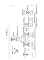
- the figure which shows an example of a structure of the vehicle charging system by one Embodiment of this invention The figure which shows the example in case the vehicle 1 provided with the charge control apparatus by one Embodiment of this invention charges a main battery.
- the figure which shows the example of the operation panel with which the vehicle by one Embodiment of this invention is provided.
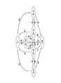
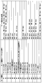
- the figure which shows the example of the mode transition in the vehicle by one Embodiment of this invention The figure which shows the example of the mode transition condition in the vehicle by one Embodiment of this invention, and the process at the time of transition.
- FIG. 1 is a diagram illustrating an example of a configuration of a vehicle charging system 200 according to an embodiment of the present invention.
- the vehicle charging system 200 according to the present embodiment includes a vehicle 1, a first power supply device 2, and a second power supply device 3.
- the vehicle 1 includes a charge control device 10, a switch control unit 20, a secondary battery 30, a drive inverter 40, a travel motor 50, an auxiliary inverter 60, a battery system controller 70, and battery management.
- Unit 80 load 90 such as air conditioning, pantograph 100 (100a, 100b), connector 110, operation panel 120, DC voltage source 130, switch SW2, switch SW3, switch SW4, switch SW5 With.
- the charging control device 10 included in the vehicle 1 includes a power receiving unit 101, a charging instruction output unit 102, and a travel instruction output unit 103.
- the secondary battery 30 included in the vehicle 1 includes a switch SW1.
- the first power supply device 2 includes a terminal charger 201, a P-pole terminal 202a, and an N-pole terminal 202b.
- the second power supply device 3 includes a depot charger 301 and a connector 302.
- the power receiving unit 101 included in the charging control device 10 receives power from the first power supply device 2 when present in a power supply area that allows power supply from the first power supply device 2. In addition, the power receiving unit 101 receives power from the second power feeding device 3 when power feeding from the second power feeding device 3 becomes possible via the connector 110.
- the charging instruction output unit 102 included in the charging control device 10 outputs various charging instructions. Specifically, the charging instruction output unit 102 outputs a terminal charging start instruction when the power receiving unit 101 charges the secondary battery 30 with the power received from the first power supply device 2. The charging instruction output unit 102 outputs a terminal charging standby instruction when the power receiving unit 101 is on standby to charge the secondary battery 30 with the power received from the first power supply device 2. The charging instruction output unit 102 outputs a depot charging start instruction when the power receiving unit 101 charges the secondary battery 30 with the power received from the second power supply device 3. The charging instruction output unit 102 outputs a depot charging standby instruction when the power receiving unit 101 is on standby to charge the secondary battery 30 with the power received from the second power supply device 3.
- the charging instruction output unit 102 outputs a terminal charging stop instruction when the power receiving unit 101 stops charging the secondary battery 30 with the power received from the first power supply device 2.
- the charging instruction output unit 102 outputs a terminal charging standby stop instruction when the power receiving unit 101 stops standby for charging the secondary battery 30 with the power received from the first power supply device 2.
- the charging instruction output unit 102 outputs a depot charging stop instruction when the power receiving unit 101 stops charging the secondary battery 30 with the power received from the second power supply device 3.
- the charging instruction output unit 102 outputs a depot charging standby stop instruction when the power receiving unit 101 stops standby for charging the secondary battery 30 with the power received from the second power supply device 3.
- the travel instruction output unit 103 included in the charge control device 10 outputs various travel instructions. Specifically, the travel instruction output unit 103 outputs a travel start instruction when the vehicle 1 travels. The travel instruction output unit 103 included in the charging control device 10 outputs a travel prohibition instruction when prohibiting travel of the vehicle 1. The charging control device 10 outputs a charging start instruction when charging the secondary battery 30 with the power fed from the first power feeding device 2 or the second power feeding device 3, and travels when the vehicle 1 travels. Output start instructions.
- the switch control unit 20 controls opening and closing of the switches SW1 to SW5 based on a charge start instruction from the charge instruction output unit 102 included in the charge control device 10 and a travel start instruction from the travel instruction output unit 103.
- the secondary battery 30 is a power source that drives the traveling motor 50.
- the drive inverter 40 converts the DC voltage output from the secondary battery 30 into a voltage for driving the traveling motor 50.
- the auxiliary inverter 60 is connected to the DC voltage output from the secondary battery 30 or the voltage output from the DC voltage source 130 to which the battery system controller 70 and the battery management unit 80 are connected (for example, 12 volts, 24 volts). Etc.) is converted into a voltage for driving a load 90 such as an air conditioner and other devices.
- the battery system controller 70 communicates with the battery management system and manages the voltage of the entire battery system.
- the battery management unit 80 manages the cell voltage of the main battery that is the secondary battery 30, and transmits the information to the battery system controller 70.
- the load 90 is a load driven by the voltage converted by the auxiliary inverter 60.
- the load 90 is air conditioning or the like.
- the pantograph 100 (100a, 100b) is connected to a terminal 202 (202a, 202b) included in the first power supply device 2 and receives power from the terminal charger 201.
- the connector 110 is connected to the connector 302 included in the second power supply device 3 and receives power from the depot charger 301.
- the operation panel 120 outputs a signal corresponding to the operation of the driver or the like to the charging instruction output unit 102 and the travel instruction output unit 103.
- the DC voltage source 130 is connected to the battery system controller 70 and the battery management unit 80.
- the DC voltage source 130 supplies a DC voltage that drives the battery system controller 70 and the battery management unit 80.
- the switch SW1 connects or disconnects the secondary battery 30 and the switches SW2 and SW3.
- the switch SW2 connects or disconnects the switch SW1 and the drive inverter 40.
- Switch SW3 connects or disconnects switch SW1 and auxiliary inverter 60.
- the switch SW4 connects or disconnects the power receiving unit 101 and the pantograph 100 included in the charging control device 10.
- the switch SW5 connects or disconnects the power receiving unit 101 and the connector 110 included in the charging control device 10.
- the first power supply device 2 includes a terminal charger 201 and terminals 202 (202a, 202b).
- the first power supply device 2 is a device installed at a bus stop in order to charge the secondary battery 30 provided in the bus.
- the terminal charger 201 supplies power for charging the secondary battery 30 provided in the vehicle 1.
- the terminals 202 are a pair of terminals that are in contact with the pantograph 100.
- One of the terminals 202 is a P-pole terminal 202a, and the other of the terminals 202 is an N-pole terminal 202b.
- the 1st electric power feeder 2 supplies electric power to the vehicle 1 from the terminal charger 201 via the terminal 202.
- the second power supply device 3 includes a depot charger 301 and a connector 302.
- the 2nd electric power feeder 3 is an apparatus installed in the vehicle base where the vehicle 1 parks at night, for example.
- the depot charger 301 supplies power for charging the secondary battery 30 provided in the vehicle 1.
- the connector 302 is connected to the connector 110 included in the vehicle 1 and supplies power from the depot charger 301 to the connector 110.
- the charging control device 10 causes the switch control unit 20 to control the switches SW1 to SW3 according to the connection status of the first power supply device 2 and the second power supply device 3 and the vehicle 1.
- the vehicle 1 can suppress the start of traveling when the secondary battery 30 is charged, and can start traveling when the charging of the secondary battery 30 is completed.
- FIG. 2 is a diagram illustrating an example when the vehicle 1 including the charging control device 10 according to the embodiment of the present invention charges the main battery. Next, the control performed in the vehicle charging system 200 when the vehicle 1 including the charging control device 10 (not shown) according to the embodiment of the present invention charges the main battery will be described.
- FIG. 2 shows an example in which the vehicle 1 including the charging control device 10 according to the embodiment of the present invention receives power from the first power feeding device 2 installed at the bus stop.
- the vehicle 1 stops at a bus stop for passengers to get on and off.
- a terminal charger is installed at the bus stop and can supply power. That is, the bus stop is an example of a power supply area.
- the terminal charger includes a terminal 202 for supplying power to the outside.
- the vehicle 1 can bring the pantograph 100 included in the vehicle 1 into contact with the terminal 202 by stopping at a predetermined place at the bus stop. When the pantograph 100 and the terminal 202 are in contact, the vehicle 1 can receive power from the terminal charger.
- the vehicle 1 starts running when the main battery is charged.
- the vehicle 1 including the charging control device 10 suppresses the start of traveling when the secondary battery 30 including the main battery is charged, and the secondary battery. When the charging of 30 is completed, traveling starts.
- FIG. 3 is a diagram illustrating an example of the operation panel 120 provided in the vehicle 1 according to the embodiment of the present invention.
- the operation panel 120 is a panel for setting the charging mode and the traveling mode, and is disposed, for example, inside the cab. Since the operation panel 120 is inside the cab, the driver can easily operate the panel.
- the operation panel 120 includes a key switch SW6, an LED (Light Emitting Diode) 210, an LED 220, an LED 230, an LED 240, an LED 250, an LED 260, a push button switch 310, a push button switch 320, and a push button switch 330.
- the key switch SW6 is a switch that activates or terminates the operation panel 120.
- the push button switch 310 is a switch for setting the mode of the vehicle 1 to the travel mode.
- the LED 210 is lit while the mode of the vehicle 1 is set to the travel mode.
- the push button switch 320 is a switch for setting the mode of the vehicle 1 to a depot charging standby mode.
- the LED 220 is lit while the mode of the vehicle 1 is set to the depot charging standby mode.
- the push button switch 330 is a switch for setting the mode of the vehicle 1 to a terminal charging standby mode in which charging is performed via the pantograph 100.
- the LED 230 is lit while the mode of the vehicle 1 is set to the terminal charging standby mode.
- the mode of the vehicle 1 is stored in an internal memory (not shown) of the charging control device 10. The mode setting of the vehicle 1 is performed by rewriting this internal memory.
- the push button switch 340 is a switch for setting the mode of the vehicle 1 to a terminal charging start mode.
- the LED 240 is lit while the terminal is being charged.
- the push button switch 350 is a switch for setting a terminal charging interruption mode for interrupting terminal charging.
- the mode of vehicle 1 is set to the depot charging start mode.
- the LED 250 is lit while depot charging is performed.
- an abnormality occurs in each mode of the vehicle 1, the mode of the vehicle 1 is set to the abnormal mode.
- the LED 260 is lit while an abnormality has occurred in the vehicle 1.
- the push button switch 360 is a switch for canceling the abnormal mode and setting the mode of the vehicle 1 to the traveling mode.
- FIG. 4 is a diagram illustrating an example of mode transition in the vehicle 1 according to the embodiment of the present invention.
- the modes in the vehicle 1 according to the embodiment of the present invention are “OFF”, “REDY TSTRT (traveling mode)”, “REDY DCR (depot charging standby mode)”, “REDY TCR (terminal).
- the charging control device 10 changes the mode of the vehicle 1 to the current mode. From one to another.
- FIG. 5 is a diagram illustrating an example of mode transition conditions and processing at the time of transition in the vehicle 1 according to the embodiment of the present invention.
- FIG. 5 shows a case where an operation performed by the driver on the operation panel 120 in each mode shown in FIG. 4, that is, an operation that triggers a mode transition and an operation that triggers the mode transition.
- the process which the charge control apparatus 10 performs via the switch control part 20 is shown.
- “mode transition” in FIG. 5 corresponds to the number added to the arrow in FIG.
- the operation that triggers the mode transition is the TCR MODE button ON, and the process at the time of the mode transition is SW2 Open.
- the mode transition M3 corresponds to the arrow indicated by M3 from “REDY TSTRT” to “REDY TCR” in FIG. In “REDY TSTRT”, turn on the TCR MODE button. Then, SW2 opens and the mode transitions from “REDY TSTRT” to “REDY TCR”.
- the “OFF” mode is a mode indicating a state in which the operation panel 120 does not accept an operation.
- the operation panel 120 outputs a signal corresponding to an operation of turning on the key switch SW6 to the charging instruction output unit 102 and the travel instruction output unit 103.
- the charging instruction output unit 102 outputs a terminal charging standby stop instruction to the switch control unit 20 in accordance with the input signal.
- the travel instruction output unit 103 outputs a travel start instruction to the switch control unit 20 in accordance with the input signal.
- the switch control unit 20 controls to close the switch SW1 shown in FIG. 1, close SW2, close SW3, open SW4, and open SW5. That is, the main battery of the secondary battery 30 is connected to the drive inverter 40 and the auxiliary inverter 60 via the switches SW1 to SW3.
- the power reception unit 101 is disconnected from the first power supply device 2 and the second power supply device 3. Then, the voltage of the secondary battery 30 is converted into a voltage for driving the traveling motor 50 by the drive inverter 40. Further, the voltage of the secondary battery 30 is converted into a voltage supplied to the load 90 by the auxiliary inverter 60.
- the vehicle 1 becomes a state which can drive
- the charging control apparatus 10 changes the mode from “OFF” to “REDY TSTRT” (mode transition M1). Then, the charging control device 10 turns on the LED 210 of “REDY TSTRT”.
- the operation panel 120 outputs a signal corresponding to an operation of turning off the key switch SW6 to the charging instruction output unit 102 and the travel instruction output unit 103.
- the charging instruction output unit 102 outputs a terminal charging standby stop instruction to the switch control unit 20 in accordance with the input signal.
- the travel instruction output unit 103 outputs a travel prohibition instruction to the switch control unit 20 in accordance with the input signal.
- the switch control unit 20 controls to open the switch SW3, open the switch SW2, open the switch SW1, open SW4, and open SW5.
- the main battery of the secondary battery 30 is disconnected from the drive inverter 40 and the auxiliary inverter 60.
- the power reception unit 101 is disconnected from the first power supply device 2 and the second power supply device 3.
- the vehicle 1 enters a stopped state where neither running nor charging is performed.
- the charging control apparatus 10 changes the mode from “REDY TSTRT” to “OFF” (mode transition M2). Then, the charging control apparatus 10 turns off the LED 210 of “REDY TSTRT”.
- the pantograph 100 of the vehicle 1 contacts the terminal 202 of the first power supply device 2.
- the operation panel 120 outputs a signal corresponding to the operation to turn on the TCR MODE button. It outputs to the charge instruction output unit 102 and the travel instruction output unit 103. Then, the charging instruction output unit 102 outputs a terminal charging standby instruction to the switch control unit 20 according to the input signal.
- the travel instruction output unit 103 outputs a travel prohibition instruction to the switch control unit 20 in accordance with the input signal.
- the switch control unit 20 controls to open the switch SW2 based on the input instruction. That is, the main battery of the secondary battery 30 is disconnected from the drive inverter 40. The main battery of the secondary battery 30 is connected to the auxiliary inverter 60, and the power receiving unit 101 is disconnected from the first power supply device 2 and the second power supply device 3. Thereby, the vehicle 1 becomes a state which cannot drive
- the “REDY TCR” mode is a mode in which the vehicle 1 cannot travel when performing terminal charging. This “REDY TCR” mode prevents the vehicle 1 from starting running when the secondary battery 30 is charged.
- the push button switch 340 of the operation panel 120 is pressed to turn on the TCR STRT button.
- the operation panel 120 outputs a signal corresponding to an operation of turning on the TCR STRT button to the charging instruction output unit 102 and the travel instruction output unit 103.
- the charging instruction output unit 102 outputs a terminal charging start instruction to the switch control unit 20 according to the input signal.
- the travel instruction output unit 103 outputs a travel prohibition instruction to the switch control unit 20 in accordance with the input signal.
- the switch control unit 20 controls to close the switch SW4 based on the input instruction.
- the main battery of the secondary battery 30 is connected to the first power supply device 2 via the power receiving unit 101. Further, the main battery of the secondary battery 30 is disconnected from the drive inverter 40. The main battery of the secondary battery 30 is connected to the auxiliary inverter 60.
- the charging instruction output unit 102 outputs a charging start instruction for the secondary battery 30
- the secondary battery 30 and the traveling motor 50 are electrically insulated.
- the secondary battery 30 of the vehicle 1 receives power from the first power supply device 2 and starts charging.
- the charging control apparatus 10 changes the mode from “REDY TCR” to “CON TCR” (mode transition M4). Then, the charging control apparatus 10 turns off the LED 230 for “REDY TCR” and turns on the LED 240 for “CON TCR”.
- the “CON TCR” mode is a mode indicating that the secondary battery 30 is being charged from the first power supply device 2.
- the operation panel 120 outputs a signal corresponding to an operation of turning on the TCR STOP button from the operation panel 120 to the charge instruction output unit 102 and the travel instruction output unit 103.
- the charging instruction output unit 102 outputs a terminal charging standby instruction to the switch control unit 20 according to the input signal.
- the travel instruction output unit 103 outputs a travel prohibition instruction to the switch control unit 20 in accordance with the input signal.
- the switch control unit 20 controls to open the switch SW4 based on the input instruction. Disconnected from drive inverter 40 and connected to auxiliary inverter 60.
- the power reception unit 101 is disconnected from the first power supply device 2 and the second power supply device 3.
- the charging instruction output unit 102 outputs a charging standby instruction for the secondary battery 30
- the secondary battery 30 and the traveling motor 50 are electrically insulated.
- the secondary battery 30 being charged stops receiving power from the first power supply device 2 and completes the terminal charging process.
- the charging control device 10 can complete the terminal charging process of the secondary battery 30.
- the charging control apparatus 10 changes the mode from “CON TCR” to “REDY TCR” (mode transition M5). Then, the charging control device 10 turns off the LED 240 for “CON TCR” and turns on the LED 230 for “REDY TCR”.
- the operation panel 120 outputs a signal corresponding to an operation of turning on the DRV MODE button from the operation panel 120 to the charge instruction output unit 102 and the travel instruction output unit 103.
- the charging instruction output unit 102 outputs a terminal charging standby stop instruction to the switch control unit 20 in accordance with the input signal.
- the travel instruction output unit 103 outputs a travel start instruction to the switch control unit 20 in accordance with the input signal.
- the switch control unit 20 controls to close the switch SW2 based on the input instruction.
- the main battery of the secondary battery 30 is connected to the drive inverter 40 via the switches SW1 and SW2.
- the main battery of the secondary battery 30 is connected to the auxiliary inverter 60.
- the power receiving unit 101 is disconnected from the first power supply device 2 and the second power supply device 3. Thereby, it will be in the state in which the vehicle 1 can drive
- the charging control apparatus 10 changes the mode from “REDY TCR” to “REDY TSTRT” (mode transition M6). Then, the charging control apparatus 10 turns off the LED 230 for “REDY TCR” and turns on the LED 210 for “REDY TSTRT”.
- Depot charging can be thought of as terminal charging.
- the driver operates the accelerator, the brake, the handle, etc., stops the vehicle 1 in a power supply area such as a vehicle base equipped with the second power supply device 3, and push button switch 320 on the operation panel 120.
- a power supply area such as a vehicle base equipped with the second power supply device 3, and push button switch 320 on the operation panel 120.
- the operation panel 120 outputs a signal corresponding to an operation of turning on the DCR MODE button from the operation panel 120 to the charge instruction output unit 102 and the travel instruction output unit 103.
- the charging instruction output unit 102 outputs a depot charging standby instruction to the switch control unit 20 in accordance with the input signal.
- the travel instruction output unit 103 outputs a travel prohibition instruction to the switch control unit 20 in accordance with the input signal.
- the switch control unit 20 controls to open the switch SW2 and close the switch SW5 based on the input instruction. That is, the main battery of the secondary battery 30 is disconnected from the drive inverter 40.
- the power reception unit 101 is connected to the second power supply device 3.
- the main battery of the secondary battery 30 is connected to the auxiliary inverter 60.
- the power receiving unit 101 is disconnected from the first power supply device 2.
- the charging control device 10 changes the mode from “REDY TSTRT” to “REDY DCR” (mode transition M7). Then, the charging control device 10 turns off the LED 210 for “REDY TSTRT” and turns on the LED 220 for “REDY DCR”.
- the “REDY DCR” mode is a mode in which the vehicle 1 is not allowed to travel when performing depot charging. This “REDY DCR” mode prevents the vehicle 1 from starting running when the secondary battery 30 is charged.
- the driver connects the connector 110 of the vehicle 1 to the connector 302 of the second power feeding device 3 in the “REDY DCR” mode.
- the charging control apparatus 10 changes the mode from “REDY DCR” to “CON DCR” (mode transition M8). Then, the charging control device 10 turns off the LED 220 for “REDY DCR” and turns on the LED 250 for “CON DCR”.
- the “CON DCR” mode is a mode indicating that the secondary battery 30 is being charged from the second power supply device 3.
- the charging control apparatus 10 changes the mode from “CON DCR” to “REDY DCR” (mode transition M9). Then, the charging control device 10 turns off the “CON DCR” LED 250 and turns on the “REDY DCR” LED 220.
- the operation panel 120 outputs a signal corresponding to an operation of turning on the DRV MODE button from the operation panel 120 to the charge instruction output unit 102 and the travel instruction output unit 103.
- the charging instruction output unit 102 outputs a depot charging standby stop instruction to the switch control unit 20 in accordance with the input signal.
- the travel instruction output unit 103 outputs a travel start instruction to the switch control unit 20 in accordance with the input signal.
- the switch control unit 20 controls the switch SW2 to close and the switch SW5 to open.
- the main battery of the secondary battery 30 is connected to the drive inverter 40 via the switches SW1 and SW2.
- the power reception unit 101 is disconnected from the second power supply device 3.
- the main battery of the secondary battery 30 is connected to the auxiliary inverter 60.
- the power receiving unit 101 is disconnected from the first power supply device 2. Thereby, it will be in the state in which the vehicle 1 can drive
- the charging control device 10 changes the mode from “REDY DCR” to “REDY TSTRT” (mode transition M10). Then, the charging control device 10 turns off the LED 220 for “REDY DCR” and turns on the LED 210 for “REDY TSTRT”.
- the operation panel 120 outputs a signal corresponding to an operation of turning on the TCR MODE button from the operation panel 120 to the charge instruction output unit 102 and the travel instruction output unit 103.
- the charging instruction output unit 102 outputs a terminal charging standby instruction to the switch control unit 20 according to the input signal.
- the travel instruction output unit 103 outputs a travel prohibition instruction to the switch control unit 20 in accordance with the input signal.
- the switch control unit 20 controls to open the switch SW5 based on the input instruction. That is, the power reception unit 101 is disconnected from the second power supply device 3.
- the main battery of the secondary battery 30 is disconnected from the drive inverter 40 and connected to the auxiliary inverter 60.
- the power reception unit 101 is disconnected from the first power supply device 2.
- the charging control apparatus 10 changes the mode from “REDY DCR” to “REDY TCR” (mode transition M11). Then, the charging control apparatus 10 turns off the LED 220 for “REDY DCR” and turns on the LED 230 for “REDY TCR”.
- the operation panel 120 outputs a signal corresponding to an operation of turning on the DCR MODE button from the operation panel 120 to the charge instruction output unit 102 and the travel instruction output unit 103.
- the charging instruction output unit 102 outputs a depot charging standby instruction to the switch control unit 20 in accordance with the input signal.
- the travel instruction output unit 103 outputs a travel prohibition instruction to the switch control unit 20 in accordance with the input signal.
- the switch control unit 20 controls to close the switch SW5 based on the input instruction. That is, the power receiving unit 101 is connected to the second power feeding device 3.
- the main battery of the secondary battery 30 is disconnected from the drive inverter 40 and connected to the auxiliary inverter 60.
- the power reception unit 101 is disconnected from the first power supply device 2.
- the charging control apparatus 10 changes the mode from “REDY TCR” to “REDY DCR” (mode transition M12). Then, the charging control apparatus 10 turns off the LED 230 for “REDY TCR” and turns on the LED 220 for “REDY DCR”.
- operation panel 120 outputs a signal corresponding to an operation to turn off key switch SW6 from operation panel 120 to charging instruction output unit 102 and travel instruction output unit 103.
- the charging instruction output unit 102 outputs a depot charging stop instruction to the switch control unit 20 in accordance with the input signal.
- the travel instruction output unit 103 outputs a travel prohibition instruction to the switch control unit 20 in accordance with the input signal.
- the switch control unit 20 controls to open the switch SW3, open the switch SW1, and open the switch SW5. That is, the main battery of the secondary battery 30 is disconnected from the drive inverter 40 and the auxiliary inverter 60.
- the power reception unit 101 is disconnected from the second power supply device 3.
- the power reception unit 101 is disconnected from the first power supply device 2.
- the vehicle 1 enters a stopped state where neither running nor charging is performed.
- the charging control apparatus 10 changes the mode from “CON DCR” to “OFF” (mode transition M13). Then, the charging control device 10 turns off the “CON DCR” LED 250.
- operation panel 120 outputs a signal corresponding to an operation to turn off key switch SW6 from operation panel 120 to charging instruction output unit 102 and travel instruction output unit 103.
- the charging instruction output unit 102 outputs a depot charging standby stop instruction to the switch control unit 20 in accordance with the input signal.
- the travel instruction output unit 103 outputs a travel prohibition instruction to the switch control unit 20 in accordance with the input signal.
- the switch control unit 20 controls to open the switch SW3, open the switch SW1, and open the switch SW5.
- the main battery of the secondary battery 30 is disconnected from the drive inverter 40 and the auxiliary inverter 60.
- the power reception unit 101 is disconnected from the second power supply device 3.
- the power reception unit 101 is disconnected from the first power supply device 2.
- operation panel 120 outputs a signal corresponding to an operation to turn off key switch SW6 from operation panel 120 to charging instruction output unit 102 and travel instruction output unit 103.
- the charging instruction output unit 102 outputs a terminal charging standby stop instruction to the switch control unit 20 in accordance with the input signal.
- the travel instruction output unit 103 outputs a travel prohibition instruction to the switch control unit 20 in accordance with the input signal.
- the switch control unit 20 controls to open the switch SW3 and open the switch SW1. That is, the main battery of the secondary battery 30 is disconnected from the drive inverter 40 and the auxiliary inverter 60.
- the power receiving unit 101 is disconnected from the first power supply device 2 and the second power supply device 3. As a result, the vehicle 1 enters a stopped state where neither running nor charging is performed. At this time, the charging control apparatus 10 changes the mode from “REDY TCR” to “OFF” (mode transition M15). Then, the charging control device 10 turns off the LED 230 of “REDY TCR”.
- operation panel 120 outputs a signal corresponding to an operation to turn off key switch SW6 from operation panel 120 to charging instruction output unit 102 and travel instruction output unit 103.
- the charging instruction output unit 102 outputs a terminal charging stop instruction to the switch control unit 20 in accordance with the input signal.
- the travel instruction output unit 103 outputs a travel prohibition instruction to the switch control unit 20 in accordance with the input signal.
- the switch control unit 20 controls to open the switch SW3, open the switch SW1, and open the switch SW4. That is, the main battery of the secondary battery 30 is disconnected from the drive inverter 40 and the auxiliary inverter 60.
- the power receiving unit 101 is disconnected from the first power supply device 2.
- the power reception unit 101 is disconnected from the second power supply device 3.
- the vehicle 1 enters a stopped state where neither running nor charging is performed.
- the charging control apparatus 10 changes the mode from “CON TCR” to “OFF” (mode transition M16). Then, the charging control device 10 turns off the LED 240 of “CON TCR”.
- a device such as the battery system controller 70 or the battery management unit 80 detects an abnormality such as a voltage
- the device that detects the abnormality outputs an abnormality detection signal to the switch control unit 20.
- the switch control unit 20 controls to open all the switches when an abnormality detection signal is input.
- the charging control apparatus 10 changes the mode from each mode to “ALARM” (mode transition M17). Then, the charging control device 10 causes the “ALARM” LED 260 to blink.
- the operation panel 120 outputs a signal corresponding to an operation of turning on the RESET button from the operation panel 120 to the charge instruction output unit 102 and the travel instruction output unit 103.
- the charging instruction output unit 102 outputs a terminal charging standby stop instruction to the switch control unit 20 in accordance with the input signal.
- the travel instruction output unit 103 outputs a travel start instruction to the switch control unit 20 in accordance with the input signal.
- the switch control unit 20 controls to close the switch SW1, close SW2, close SW3, open SW4, and open SW5.
- the main battery of the secondary battery 30 is connected to the drive inverter 40 and the auxiliary inverter 60 via the switches SW1 to SW3.
- the power reception unit 101 is disconnected from the first power supply device 2 and the second power supply device 3.
- the charging control apparatus 10 changes the mode from “ALARM” to “REDY TSTRT” (mode transition M18).
- the charging control device 10 turns off the “ALARM” LED 260 and turns on the “REDY TSTRT” LED 210.
- the vehicle 1 can be prevented from starting traveling when the secondary battery 30 is charged, and the vehicle 1 can start traveling when the charging of the secondary battery 30 is completed. In other cases, the button operation is invalid and no mode transition occurs.
- mode transition 4 detects contact between the pantograph 100 and the terminal 202. Then, the computer of the charging control device 10 transmits a signal to the charging instruction output unit 102 and the travel instruction output unit 103 based on the algorithm of the program to be read and executed and the detection result of the contact between the pantograph 100 and the terminal 202. . Then, the charging instruction output unit 102 may output a charging instruction based on the input signal. The travel instruction output unit 103 may output a travel instruction based on the detection result of the end of charging.
- mode transition 5 detects that the charging rate of secondary battery 30 exceeds a threshold value.
- the computer of the charging control apparatus 10 may perform mode transition by automatically determining based on the algorithm of the program to be read and executed and the detection result.
- the mode transition may be a combination of a mode transition in which the driver operates the operation panel 120 and a mode transition automatically determined based on the algorithm of the program executed by the computer and the detection result of the end of charging.
- the vehicle charging system 200 is not limited to it.
- the vehicle charging system 200 may include only the first power feeding device 2 as a power feeding device.
- the 1st electric power feeder 2 which the secondary battery 30 performs in the above embodiment demonstrated as what charges via the pantograph 100, the 1st electric power feeder 2 which the secondary battery 30 performs Charging from is not limited to this.
- the charging from the first power supply device 2 performed by the secondary battery 30 may be non-contact charging.
- the switch in the present invention may be any switch as long as it operates properly.
- the switch may be a transmission gate using a transistor.
- the charging control device 10 according to the present invention may function as a part of the battery system controller 70.
- the charging control apparatus 10 includes a power receiving unit 101, a charging instruction output unit 102, and a travel instruction output unit 103.
- the power receiving unit 101 receives power from the first power supply device 2 when the power reception unit 101 is present in a power supply area that enables power supply from the first power supply device 2.
- the charging instruction output unit 102 outputs a charging instruction related to charging the secondary battery 30 with the power received by the power receiving unit 101.
- the travel instruction output unit 103 outputs a travel instruction related to travel of the vehicle.
- the charging instruction output unit 102 When the charging instruction output unit 102 outputs a charging start instruction among the charging instructions for the secondary battery 30, the secondary battery 30 and the traveling motor 50 are electrically insulated, and the traveling instruction output unit 103 is the vehicle.
- the traveling instruction output unit 103 When the travel start instruction 1 is output, the secondary battery 30 and the travel motor 50 are electrically connected. If it does in this way, it can suppress that vehicle 1 starts a run, when secondary battery 30 is charged, and vehicle 1 can start a run when the charge of secondary battery 30 is completed.
- the above-mentioned charge control apparatus 10 has a computer system inside.
- the process described above is stored in a computer-readable recording medium in the form of a program, and the above process is performed by the computer reading and executing this program.
- the computer-readable recording medium means a magnetic disk, a magneto-optical disk, a CD-ROM, a DVD-ROM, a semiconductor memory, or the like.
- the computer program may be distributed to the computer via a communication line, and the computer that has received the distribution may execute the program.
- the program may be for realizing a part of the above-described functions. Furthermore, what can implement
- the vehicle when the secondary battery is charged, the vehicle is prevented from starting running, and when the secondary battery is completely charged.
- the vehicle can start running.
Landscapes
- Engineering & Computer Science (AREA)
- Power Engineering (AREA)
- Transportation (AREA)
- Mechanical Engineering (AREA)
- Life Sciences & Earth Sciences (AREA)
- Sustainable Development (AREA)
- Sustainable Energy (AREA)
- Charge And Discharge Circuits For Batteries Or The Like (AREA)
- Electric Propulsion And Braking For Vehicles (AREA)
Abstract
この充電制御装置は、受電部と、充電指示出力部と、走行指示出力部と、を備える。受電部は、給電装置からの給電を可能とする給電エリアに存在するときに前記給電装置から電力を受電する。充電指示出力部は、受電部が受電した電力による二次電池の充電に係る充電指示を出力する。走行指示出力部は、充電制御装置を備える車両の走行に係る走行指示を出力する。充電指示出力部が二次電池の充電指示のうち充電開始指示を出力したときに、二次電池と走行用モータとが電気的に絶縁されており、走行指示出力部が車両の走行開始指示を出力したときに、二次電池と走行用モータとが電気的に接続されている。
Description
本発明は、充電制御装置、車両、車両充電システム、充電制御方法、及びプログラムに関する。
本願は、2013年11月5日に、日本に出願された特願2013-229278号に基づき優先権を主張し、その内容をここに援用する。
本願は、2013年11月5日に、日本に出願された特願2013-229278号に基づき優先権を主張し、その内容をここに援用する。
プラグインハイブリッド車などの車両が搭載する二次電池の中には、交流100ボルトの電源から車載充電器を介して充電する通常充電と、交流200ボルトの電源から地上据え置き充電器を介して充電する急速充電の両方ができるものがある。
特許文献1には、二次電池の充電時に、急速充電用プラグと通常充電用プラグの両方が車両に接続されているとき、状況に応じた多様な充電方法を提供する技術が記載されている。
特許文献1には、二次電池の充電時に、急速充電用プラグと通常充電用プラグの両方が車両に接続されているとき、状況に応じた多様な充電方法を提供する技術が記載されている。
プラグインハイブリッド車は、インターロックを備えており、プラグが充電器に接続されている場合に車両が走行できないように設定されているものがある。プラグインハイブリッド車の制御装置は、このインターロックの設定により、二次電池が充電されているときに車両が走行を開始することを抑制している。そして、ユーザによってプラグが充電器から外された場合に制御装置はインターロックの設定を解除し、プラグインハイブリッド車は走行可能状態となる。
しかしながら、車両が例えばパンタグラフを介して充電を行う電気バスである場合、二次電池の充電が完了してもパンタグラフが充電器側に接触したままである。そのため、パンタグラフを介して充電を行うような車両では、プラグインハイブリッド車のように、パンタグラフが充電器側に接触していることを条件にインターロックの設定を行うことができない。従って、パンタグラフを介して充電を行うような車両は、二次電池が充電中であるにも関わらず、走行を開始する可能性がある。
そのため、パンタグラフを介して充電を行うような車両では、二次電池が充電されているときに車両が走行を開始することを抑制し、二次電池の充電完了時に車両が走行を開始するための技術が求められていた。
本発明は、二次電池が充電されているときに車両が走行を開始することを抑制し、二次電池の充電完了時に車両が走行を開始することのできる充電制御装置、車両、車両充電システム、充電制御方法、及びプログラムを提供する。
しかしながら、車両が例えばパンタグラフを介して充電を行う電気バスである場合、二次電池の充電が完了してもパンタグラフが充電器側に接触したままである。そのため、パンタグラフを介して充電を行うような車両では、プラグインハイブリッド車のように、パンタグラフが充電器側に接触していることを条件にインターロックの設定を行うことができない。従って、パンタグラフを介して充電を行うような車両は、二次電池が充電中であるにも関わらず、走行を開始する可能性がある。
そのため、パンタグラフを介して充電を行うような車両では、二次電池が充電されているときに車両が走行を開始することを抑制し、二次電池の充電完了時に車両が走行を開始するための技術が求められていた。
本発明は、二次電池が充電されているときに車両が走行を開始することを抑制し、二次電池の充電完了時に車両が走行を開始することのできる充電制御装置、車両、車両充電システム、充電制御方法、及びプログラムを提供する。
本発明の第1の態様によれば、充電制御装置は、受電部と、充電指示出力部と、走行指示出力部とを備える。受電部は、給電装置からの給電を可能とする給電エリアに存在するときに前記給電装置から電力を受電する。充電指示出力部は、前記受電部が受電した電力による二次電池の充電に係る充電指示を出力する。走行指示出力部は、車両の走行に係る走行指示を出力する。前記充電指示出力部が前記二次電池の充電指示のうち充電開始指示を出力したときに、前記二次電池と走行用モータとが電気的に絶縁されており、前記走行指示出力部が前記車両の走行開始指示を出力したときに、前記二次電池と前記走行用モータとが電気的に接続されている。
本発明の第2の態様によれば、前記充電制御装置が備える前記充電指示出力部は、ボタンの押下に基づいて前記充電指示を出力し、前記走行指示出力部は、ボタンの押下に基づいて走行開始指示を出力する。
本発明の第3の態様によれば、前記充電制御装置が備える前記ボタンは、前記車両の運転室の内部に設けられたパネルに備えられる。
本発明の第4の態様によれば、前記充電制御装置が備える前記充電指示出力部は、充電制御装置のコンピュータが読み出して実行するプログラムのアルゴリズムに基づいて前記充電指示を出力し、前記走行指示出力部は、前記充電制御装置のコンピュータが読み出して実行するプログラムのアルゴリズムに基づいて走行指示を出力する。
本発明の第5の態様によれば、前記充電制御装置が備える前記受電部は、パンタグラフを介して給電装置から電力を受電する。
本発明の第6の態様によれば、前記充電制御装置が備える前記受電部は、コネクタを介して給電装置から電力を受電する。
本発明の第7の態様によれば、車両は前記充電制御装置を備える。
本発明の第8の態様によれば、車両充電システムは、前記車両の受電部を介して給電する給電装置と前記車両とを備える。
本発明の第9の態様によれば、充電制御方法は、給電装置からの給電を可能とする給電エリアに存在するときに前記給電装置から電力を受電し、受電した電力による二次電池の充電に係る充電指示を出力し、充電制御方法を備える車両の走行に係る走行指示を出力し、前記二次電池の充電指示のうち充電開始指示を出力したときに、前記二次電池と走行用モータとが電気的に絶縁されており、前記車両の走行開始指示を出力したときに、前記二次電池とは前記走行用モータとが電気的に接続されている。
本発明の第10の態様によれば、プログラムは、充電制御装置のコンピュータを、給電装置からの給電を可能とする給電エリアに存在するときに前記給電装置から電力を受電する受電手段と、前記受電手段が受電した電力による二次電池の充電に係る充電指示を出力する充電開始指示出力手段と、自装置を備える車両の走行に係る走行指示を出力する走行開始指示出力手段として機能させ、前記充電開始指示出力手段が前記二次電池の充電指示のうち充電開始指示を出力したときに、前記二次電池と走行用モータとを電気的に絶縁させた状態とし、前記走行開始指示出力手段が前記車両の走行開始指示を出力したときに、前記二次電池と前記走行用モータとを電気的に接続させた状態とする。
上述の充電制御装置、車両、車両充電システム、充電制御方法、及びプログラムによれば、二次電池が充電されているときに車両が走行を開始することを抑制し、二次電池の充電完了時に車両が走行を開始することができる。
以下、実施形態について図面を参照して説明する。
図1は、本発明の一実施形態による車両充電システム200の構成の一例を示す図である。
図1で示すように、本実施形態による車両充電システム200は、車両1と、第一の給電装置2と、第二の給電装置3とを備える。
図1は、本発明の一実施形態による車両充電システム200の構成の一例を示す図である。
図1で示すように、本実施形態による車両充電システム200は、車両1と、第一の給電装置2と、第二の給電装置3とを備える。
車両1は、充電制御装置10と、スイッチ制御部20と、二次電池30と、駆動インバータ40と、走行用モータ50と、補機インバータ60と、バッテリ・システム・コントローラ70と、バッテリ・マネジメント・ユニット80と、空調などの負荷90と、パンタグラフ100(100a、100b)と、コネクタ110と、操作パネル120と、直流電圧源130と、スイッチSW2と、スイッチSW3と、スイッチSW4と、スイッチSW5とを備える。
車両1が備える充電制御装置10は、受電部101と、充電指示出力部102と、走行指示出力部103とを備える。
車両1が備える二次電池30は、スイッチSW1を備える。
第一の給電装置2は、ターミナル充電器201と、P極の端子202aと、N極の端子202bとを備える。
第二の給電装置3は、デポ充電器301と、コネクタ302とを備える。
車両1が備える充電制御装置10は、受電部101と、充電指示出力部102と、走行指示出力部103とを備える。
車両1が備える二次電池30は、スイッチSW1を備える。
第一の給電装置2は、ターミナル充電器201と、P極の端子202aと、N極の端子202bとを備える。
第二の給電装置3は、デポ充電器301と、コネクタ302とを備える。
充電制御装置10が備える受電部101は、第一の給電装置2からの給電を可能とする給電エリアに存在するときに第一の給電装置2から電力を受電する。また、受電部101は、コネクタ110を介して第二の給電装置3からの給電が可能となったときに第二の給電装置3から電力を受電する。
充電制御装置10が備える充電指示出力部102は、各種の充電指示を出力する。具体的には、充電指示出力部102は、受電部101が第一の給電装置2から受電した電力により二次電池30の充電を行うときにターミナル充電開始指示を出力する。充電指示出力部102は、受電部101が第一の給電装置2から受電した電力により二次電池30の充電を行うために待機しているときにターミナル充電待機指示を出力する。充電指示出力部102は、受電部101が第二の給電装置3から受電した電力により二次電池30の充電を行うときにデポ充電開始指示を出力する。充電指示出力部102は、受電部101が第二の給電装置3から受電した電力により二次電池30の充電を行うために待機しているときにデポ充電待機指示を出力する。充電指示出力部102は、受電部101が第一の給電装置2から受電した電力による二次電池30の充電を停止するときにターミナル充電停止指示を出力する。充電指示出力部102は、受電部101が第一の給電装置2から受電した電力により二次電池30の充電を行うための待機を停止するときにターミナル充電待機停止指示を出力する。充電指示出力部102は、受電部101が第二の給電装置3から受電した電力による二次電池30の充電を停止するときにデポ充電停止指示を出力する。充電指示出力部102は、受電部101が第二の給電装置3から受電した電力により二次電池30の充電を行うための待機を停止するときにデポ充電待機停止指示を出力する。
充電制御装置10が備える走行指示出力部103は、各種の走行指示を出力する。具体的には、走行指示出力部103は、車両1を走行させるときに走行開始指示を出力する。充電制御装置10が備える走行指示出力部103は、車両1の走行を禁止させるときに走行禁止指示を出力する。
充電制御装置10は、第一の給電装置2または第二の給電装置3から給電される電力で二次電池30の充電を行うときに充電開始指示を出力し、車両1を走行させるときに走行開始指示を出力する。
充電制御装置10は、第一の給電装置2または第二の給電装置3から給電される電力で二次電池30の充電を行うときに充電開始指示を出力し、車両1を走行させるときに走行開始指示を出力する。
スイッチ制御部20は、充電制御装置10が備える充電指示出力部102からの充電開始指示や走行指示出力部103からの走行開始指示に基づいて、スイッチSW1~SW5の開閉を制御する。
二次電池30は、走行用モータ50を駆動する電力源である。
駆動インバータ40は、二次電池30が出力する直流電圧を、走行用モータ50を駆動するための電圧に変換する。
二次電池30は、走行用モータ50を駆動する電力源である。
駆動インバータ40は、二次電池30が出力する直流電圧を、走行用モータ50を駆動するための電圧に変換する。
補機インバータ60は、二次電池30が出力する直流電圧や、バッテリ・システム・コントローラ70やバッテリ・マネジメント・ユニット80が接続されている直流電圧源130が出力する電圧(例えば12ボルト、24ボルトなど)を、空調などの負荷90やその他の装置を駆動するための電圧に変換する。
バッテリ・システム・コントローラ70は、バッテリ・マネジメント・システムと通信し、バッテリ・システム全体の電圧を管理する。
バッテリ・マネジメント・ユニット80は、二次電池30であるメインバッテリのセル電圧を管理し、その情報をバッテリ・システム・コントローラ70に送信する。
バッテリ・システム・コントローラ70は、バッテリ・マネジメント・システムと通信し、バッテリ・システム全体の電圧を管理する。
バッテリ・マネジメント・ユニット80は、二次電池30であるメインバッテリのセル電圧を管理し、その情報をバッテリ・システム・コントローラ70に送信する。
負荷90は、補機インバータ60が変換した電圧で駆動される負荷である。負荷90は、空調などである。
パンタグラフ100(100a、100b)は、第一の給電装置2が備える端子202(202a、202b)に接続し、ターミナル充電器201から電力を受電する。
コネクタ110は、第二の給電装置3が備えるコネクタ302に接続し、デポ充電器301から電力を受電する。
操作パネル120は、運転手などの操作に応じた信号を充電指示出力部102や走行指示出力部103に出力する。
直流電圧源130は、バッテリ・システム・コントローラ70やバッテリ・マネジメント・ユニット80に接続されている。直流電圧源130は、バッテリ・システム・コントローラ70やバッテリ・マネジメント・ユニット80を駆動する直流電圧を供給する。
パンタグラフ100(100a、100b)は、第一の給電装置2が備える端子202(202a、202b)に接続し、ターミナル充電器201から電力を受電する。
コネクタ110は、第二の給電装置3が備えるコネクタ302に接続し、デポ充電器301から電力を受電する。
操作パネル120は、運転手などの操作に応じた信号を充電指示出力部102や走行指示出力部103に出力する。
直流電圧源130は、バッテリ・システム・コントローラ70やバッテリ・マネジメント・ユニット80に接続されている。直流電圧源130は、バッテリ・システム・コントローラ70やバッテリ・マネジメント・ユニット80を駆動する直流電圧を供給する。
スイッチSW1は、二次電池30と、スイッチSW2及びスイッチSW3とを接続または遮断する。
スイッチSW2は、スイッチSW1と駆動インバータ40とを接続または遮断する。
スイッチSW3は、スイッチSW1と補機インバータ60とを接続または遮断する。
スイッチSW4は、充電制御装置10が備える受電部101とパンタグラフ100とを接続または遮断する。
スイッチSW5は、充電制御装置10が備える受電部101とコネクタ110とを接続または遮断する。
スイッチSW2は、スイッチSW1と駆動インバータ40とを接続または遮断する。
スイッチSW3は、スイッチSW1と補機インバータ60とを接続または遮断する。
スイッチSW4は、充電制御装置10が備える受電部101とパンタグラフ100とを接続または遮断する。
スイッチSW5は、充電制御装置10が備える受電部101とコネクタ110とを接続または遮断する。
第一の給電装置2は、ターミナル充電器201と、端子202(202a、202b)とを備える。第一の給電装置2は、例えば車両1がバスである場合、バスが備える二次電池30を充電するためにバス停に設置されている装置である。
ターミナル充電器201は、車両1が備える二次電池30を充電する電力を供給する。
端子202は、パンタグラフ100と接触する1対の端子である。端子202の一方はP極の端子202aであり、端子202の他方はN極の端子202bである。
そして、第一の給電装置2は、端子202を介してターミナル充電器201から車両1に電力を供給する。
ターミナル充電器201は、車両1が備える二次電池30を充電する電力を供給する。
端子202は、パンタグラフ100と接触する1対の端子である。端子202の一方はP極の端子202aであり、端子202の他方はN極の端子202bである。
そして、第一の給電装置2は、端子202を介してターミナル充電器201から車両1に電力を供給する。
第二の給電装置3は、デポ充電器301と、コネクタ302とを備える。第二の給電装置3は、例えば車両1が夜間に駐車する車両基地に設置されている装置である。
デポ充電器301は、車両1が備える二次電池30を充電する電力を供給する。
コネクタ302は、車両1が備えるコネクタ110に接続し、デポ充電器301からコネクタ110に電力を供給する。
デポ充電器301は、車両1が備える二次電池30を充電する電力を供給する。
コネクタ302は、車両1が備えるコネクタ110に接続し、デポ充電器301からコネクタ110に電力を供給する。
上述した構成により、充電制御装置10は、第一の給電装置2及び第二の給電装置3と車両1との接続状況に応じてスイッチ制御部20にスイッチSW1~SW3を制御させる。これにより、車両1は二次電池30が充電されているときに走行を開始することを抑制し、二次電池30の充電完了時に走行を開始できる。
図2は、本発明の一実施形態による充電制御装置10を備える車両1がメインバッテリを充電する場合の例を示す図である。
次に、本発明の一実施形態による充電制御装置10(図示せず)を備える車両1がメインバッテリを充電する場合に、車両充電システム200で行われる制御について説明する。
次に、本発明の一実施形態による充電制御装置10(図示せず)を備える車両1がメインバッテリを充電する場合に、車両充電システム200で行われる制御について説明する。
この図2は、本発明の一実施形態による充電制御装置10を備える車両1が、バス停に設置された第一の給電装置2から電力を受電する場合の例を示している。
車両1は、乗客が乗降するためにバス停に停車する。バス停にはターミナル充電器が設置されており、給電できる。つまり、バス停は給電エリアの一例である。ターミナル充電器は、電力を外部に供給するための端子202を備えている。車両1は、バス停において所定の場所に停車することで、車両1が備えるパンタグラフ100を端子202に接触させることができる。パンタグラフ100と端子202が接触することで、車両1は、ターミナル充電器から電力を受電することができる。
車両1は、乗客が乗降するためにバス停に停車する。バス停にはターミナル充電器が設置されており、給電できる。つまり、バス停は給電エリアの一例である。ターミナル充電器は、電力を外部に供給するための端子202を備えている。車両1は、バス停において所定の場所に停車することで、車両1が備えるパンタグラフ100を端子202に接触させることができる。パンタグラフ100と端子202が接触することで、車両1は、ターミナル充電器から電力を受電することができる。
メインバッテリが充電されているときに、車両1が走行を開始することは好ましくない。
本発明の一実施形態による充電制御装置10を備える車両1は、以下に示すように、メインバッテリを備える二次電池30が充電されているときに走行を開始することを抑制し、二次電池30の充電完了時に走行を開始する。
本発明の一実施形態による充電制御装置10を備える車両1は、以下に示すように、メインバッテリを備える二次電池30が充電されているときに走行を開始することを抑制し、二次電池30の充電完了時に走行を開始する。
図3は、本発明の一実施形態による車両1が備える操作パネル120の例を示す図である。
操作パネル120は、充電モードや走行モードを設定するためのパネルであり、例えば、運転室の内部に配置されている。操作パネル120が運転室の内部にあることで、運転手はパネル操作を容易に行うことができる。
操作パネル120は、キースイッチSW6と、LED(Light Emitting Diode)210と、LED220と、LED230と、LED240と、LED250と、LED260と、押しボタンスイッチ310と、押しボタンスイッチ320と、押しボタンスイッチ330と、押しボタンスイッチ340と、押しボタンスイッチ350と、押しボタンスイッチ360とを備える。
操作パネル120は、充電モードや走行モードを設定するためのパネルであり、例えば、運転室の内部に配置されている。操作パネル120が運転室の内部にあることで、運転手はパネル操作を容易に行うことができる。
操作パネル120は、キースイッチSW6と、LED(Light Emitting Diode)210と、LED220と、LED230と、LED240と、LED250と、LED260と、押しボタンスイッチ310と、押しボタンスイッチ320と、押しボタンスイッチ330と、押しボタンスイッチ340と、押しボタンスイッチ350と、押しボタンスイッチ360とを備える。
キースイッチSW6は、操作パネル120を起動または終了するスイッチである。
押しボタンスイッチ310は、車両1のモードを走行モードに設定するためのスイッチである。
LED210は、車両1のモードが走行モードに設定されている間点灯する。
押しボタンスイッチ320は、車両1のモードをデポ充電の待機モードに設定するためのスイッチである。
LED220は、車両1のモードがデポ充電の待機モードに設定されている間点灯する。
押しボタンスイッチ330は、パンタグラフ100を介して充電を行うターミナル充電の待機モードに車両1のモードを設定するためのスイッチである。
LED230は、車両1のモードがターミナル充電の待機モードに設定されている間点灯する。
車両1のモードは、充電制御装置10の図示していない内部メモリに記憶されている。車両1のモード設定は、この内部メモリを書き換えることによって行われる。
押しボタンスイッチ310は、車両1のモードを走行モードに設定するためのスイッチである。
LED210は、車両1のモードが走行モードに設定されている間点灯する。
押しボタンスイッチ320は、車両1のモードをデポ充電の待機モードに設定するためのスイッチである。
LED220は、車両1のモードがデポ充電の待機モードに設定されている間点灯する。
押しボタンスイッチ330は、パンタグラフ100を介して充電を行うターミナル充電の待機モードに車両1のモードを設定するためのスイッチである。
LED230は、車両1のモードがターミナル充電の待機モードに設定されている間点灯する。
車両1のモードは、充電制御装置10の図示していない内部メモリに記憶されている。車両1のモード設定は、この内部メモリを書き換えることによって行われる。
押しボタンスイッチ340は、車両1のモードをターミナル充電の開始モードに設定するためのスイッチである。
LED240は、ターミナル充電が行われている間点灯する。
押しボタンスイッチ350は、ターミナル充電を中断するターミナル充電の中断モードに設定するためのスイッチである。
デポ充電の待機モードにおいてコネクタ110とコネクタ302とが接続されると、車両1のモードはデポ充電の開始モードに設定される。
LED250は、デポ充電が行われている間点灯する。
車両1の各モードにおいて異常が発生すると、車両1のモードは異常モードに設定される。
LED260は、車両1に異常が発生している間点灯する。
押しボタンスイッチ360は、異常モードを解除し、車両1のモードを走行モードに設定するためのスイッチである。
LED240は、ターミナル充電が行われている間点灯する。
押しボタンスイッチ350は、ターミナル充電を中断するターミナル充電の中断モードに設定するためのスイッチである。
デポ充電の待機モードにおいてコネクタ110とコネクタ302とが接続されると、車両1のモードはデポ充電の開始モードに設定される。
LED250は、デポ充電が行われている間点灯する。
車両1の各モードにおいて異常が発生すると、車両1のモードは異常モードに設定される。
LED260は、車両1に異常が発生している間点灯する。
押しボタンスイッチ360は、異常モードを解除し、車両1のモードを走行モードに設定するためのスイッチである。
図4は、本発明の一実施形態による車両1におけるモード遷移の例を示す図である。
この図で示すように、本発明の一実施形態による車両1におけるモードは、“OFF”、“REDY TSTRT(走行モード)”、“REDY DCR(デポ充電の待機モード)”、“REDY TCR(ターミナル充電の待機モード)”、“CON DCR(デポ充電の開始モード)”、“CON TCR(ターミナル充電の開始モード)”、“ALARM(異常モード)”の7つ存在する。
これら7つのモードは、図3で示した操作パネル120に表示されている文字と対応している。それぞれのモードにおいて、運転手が図3で示したキースイッチSW6や押しボタンスイッチ310、320、330、340、350、360を操作した場合に、充電制御装置10が車両1のモードを現在のモードから異なるモードへと遷移させる。
この図で示すように、本発明の一実施形態による車両1におけるモードは、“OFF”、“REDY TSTRT(走行モード)”、“REDY DCR(デポ充電の待機モード)”、“REDY TCR(ターミナル充電の待機モード)”、“CON DCR(デポ充電の開始モード)”、“CON TCR(ターミナル充電の開始モード)”、“ALARM(異常モード)”の7つ存在する。
これら7つのモードは、図3で示した操作パネル120に表示されている文字と対応している。それぞれのモードにおいて、運転手が図3で示したキースイッチSW6や押しボタンスイッチ310、320、330、340、350、360を操作した場合に、充電制御装置10が車両1のモードを現在のモードから異なるモードへと遷移させる。
図5は、本発明の一実施形態による車両1におけるモード遷移条件及び遷移時の処理の例を示す図である。
図5は、図4で示したそれぞれのモードにおいて、運転手が操作パネル120に対して行う操作、すなわちモード遷移のトリガとなる操作と、そのモード遷移のトリガとなる操作が行われたときに充電制御装置10がスイッチ制御部20を介して行う処理とを示している。また、図5における“モード遷移”は、図4における矢印に付加されている数字に対応している。例えば、図5におけるモード遷移M3において、モード遷移のトリガとなる操作はTCR MODEボタンONであり、そのときのモード遷移時の処理はSW2 Openである。モード遷移M3は、図4において“REDY TSTRT”から“REDY TCR”へ向かうM3で示された矢印に対応している。“REDY TSTRT”においてTCR MODEボタンをONする。すると、SW2が開き、“REDY TSTRT”から“REDY TCR”へモードが遷移する。
図5は、図4で示したそれぞれのモードにおいて、運転手が操作パネル120に対して行う操作、すなわちモード遷移のトリガとなる操作と、そのモード遷移のトリガとなる操作が行われたときに充電制御装置10がスイッチ制御部20を介して行う処理とを示している。また、図5における“モード遷移”は、図4における矢印に付加されている数字に対応している。例えば、図5におけるモード遷移M3において、モード遷移のトリガとなる操作はTCR MODEボタンONであり、そのときのモード遷移時の処理はSW2 Openである。モード遷移M3は、図4において“REDY TSTRT”から“REDY TCR”へ向かうM3で示された矢印に対応している。“REDY TSTRT”においてTCR MODEボタンをONする。すると、SW2が開き、“REDY TSTRT”から“REDY TCR”へモードが遷移する。
ここで、図4と図5を用いて運転手が操作パネル120を操作した場合のモード遷移を説明する。
運転手が操作パネル120を操作する以前は、図4で示す“OFF”モードである。“OFF”モードは、操作パネル120が操作を受け付けない状態を示すモードである。
まず、運転手が“OFF”モードにおいて、操作パネル120のキースイッチSW6をONした場合について説明する。この場合、操作パネル120は、キースイッチSW6をONする操作に応じた信号を、充電指示出力部102と走行指示出力部103に出力する。すると、充電指示出力部102は、入力した信号に応じてターミナル充電待機停止指示をスイッチ制御部20に出力する。また、走行指示出力部103は、入力した信号に応じて走行開始指示をスイッチ制御部20に出力する。スイッチ制御部20は、入力した指示に基づいて、図1で示したスイッチSW1を閉じ、SW2を閉じ、SW3を閉じ、SW4を開き、SW5を開くように制御する。つまり、二次電池30のメインバッテリがスイッチSW1~3を介して駆動インバータ40と補機インバータ60に接続される。また、受電部101は、第一の給電装置2と第二の給電装置3から切り離される。そして、二次電池30の電圧が駆動インバータ40によって走行用モータ50を駆動する電圧に変換される。また、二次電池30の電圧が補機インバータ60によって負荷90に供給する電圧に変換される。これにより、車両1は走行できる状態となる。
このとき、充電制御装置10は、モードを“OFF”から“REDY TSTRT”に遷移させる(モード遷移M1)。そして、充電制御装置10は、“REDY TSTRT”のLED210を点灯させる。
運転手が操作パネル120を操作する以前は、図4で示す“OFF”モードである。“OFF”モードは、操作パネル120が操作を受け付けない状態を示すモードである。
まず、運転手が“OFF”モードにおいて、操作パネル120のキースイッチSW6をONした場合について説明する。この場合、操作パネル120は、キースイッチSW6をONする操作に応じた信号を、充電指示出力部102と走行指示出力部103に出力する。すると、充電指示出力部102は、入力した信号に応じてターミナル充電待機停止指示をスイッチ制御部20に出力する。また、走行指示出力部103は、入力した信号に応じて走行開始指示をスイッチ制御部20に出力する。スイッチ制御部20は、入力した指示に基づいて、図1で示したスイッチSW1を閉じ、SW2を閉じ、SW3を閉じ、SW4を開き、SW5を開くように制御する。つまり、二次電池30のメインバッテリがスイッチSW1~3を介して駆動インバータ40と補機インバータ60に接続される。また、受電部101は、第一の給電装置2と第二の給電装置3から切り離される。そして、二次電池30の電圧が駆動インバータ40によって走行用モータ50を駆動する電圧に変換される。また、二次電池30の電圧が補機インバータ60によって負荷90に供給する電圧に変換される。これにより、車両1は走行できる状態となる。
このとき、充電制御装置10は、モードを“OFF”から“REDY TSTRT”に遷移させる(モード遷移M1)。そして、充電制御装置10は、“REDY TSTRT”のLED210を点灯させる。
運転手が“REDY TSTRT”モードにおいて、操作パネル120のキースイッチSW6をOFFした場合について説明する。この場合、操作パネル120は、キースイッチSW6をOFFする操作に応じた信号を、充電指示出力部102と走行指示出力部103に出力する。すると、充電指示出力部102は、入力した信号に応じてターミナル充電待機停止指示をスイッチ制御部20に出力する。また、走行指示出力部103は、入力した信号に応じて走行禁止指示をスイッチ制御部20に出力する。スイッチ制御部20は、入力した指示に基づいて、スイッチSW3を開き、スイッチSW2を開き、スイッチSW1を開き、SW4を開き、SW5を開くように制御する。つまり、二次電池30のメインバッテリは、駆動インバータ40や補機インバータ60から切り離される。また、受電部101は、第一の給電装置2と第二の給電装置3から切り離される。これにより、車両1は走行も充電もしない停止状態となる。
このとき、充電制御装置10は、モードを“REDY TSTRT”から“OFF”に遷移させる(モード遷移M2)。そして、充電制御装置10は、“REDY TSTRT”のLED210が消灯させる。
このとき、充電制御装置10は、モードを“REDY TSTRT”から“OFF”に遷移させる(モード遷移M2)。そして、充電制御装置10は、“REDY TSTRT”のLED210が消灯させる。
運転手が“REDY TSTRT”モードにおいて、アクセル、ブレーキ、ハンドルなどを操作し、第一の給電装置2を備えたバス停などの給電エリアに車両1を停車した場合について説明する。この場合、車両1のパンタグラフ100は、第一の給電装置2の端子202に接触する。ここで、運転手がターミナル充電を行うために操作パネル120の押しボタンスイッチ330を押下してTCR MODEボタンをONした場合、操作パネル120は、TCR MODEボタンをONする操作に応じた信号を、充電指示出力部102と走行指示出力部103に出力する。すると、充電指示出力部102は、入力した信号に応じてターミナル充電待機指示をスイッチ制御部20に出力する。また、走行指示出力部103は、入力した信号に応じて走行禁止指示をスイッチ制御部20に出力する。スイッチ制御部20は、入力した指示に基づいて、スイッチSW2を開くように制御する。つまり、二次電池30のメインバッテリは、駆動インバータ40から切り離される。また、二次電池30のメインバッテリは、補機インバータ60に接続されており、受電部101は、第一の給電装置2と第二の給電装置3から切り離されている。これにより、車両1は走行できない状態となる。
このとき、充電制御装置10は、モードを“REDY TSTRT”から“REDY TCR”に遷移させる(モード遷移M3)。そして、充電制御装置10は、“REDY TSTRT”のLED210を消灯させ、“REDY TCR”のLED230を点灯させる。“REDY TCR”モードは、ターミナル充電を行う際に車両1を走行できない状態にするモードである。
この“REDY TCR”モードによって、二次電池30が充電されているときに車両1が走行を開始することを抑制している。
このとき、充電制御装置10は、モードを“REDY TSTRT”から“REDY TCR”に遷移させる(モード遷移M3)。そして、充電制御装置10は、“REDY TSTRT”のLED210を消灯させ、“REDY TCR”のLED230を点灯させる。“REDY TCR”モードは、ターミナル充電を行う際に車両1を走行できない状態にするモードである。
この“REDY TCR”モードによって、二次電池30が充電されているときに車両1が走行を開始することを抑制している。
運転手が“REDY TCR”モードであり車両1のパンタグラフ100が第一の給電装置2の端子202に接触している状態において、操作パネル120の押しボタンスイッチ340を押下してTCR STRTボタンをONした場合について説明する。この場合、操作パネル120は、TCR STRTボタンをONする操作に応じた信号を、充電指示出力部102と走行指示出力部103に出力する。すると、充電指示出力部102は、入力した信号に応じてターミナル充電開始指示をスイッチ制御部20に出力する。また、走行指示出力部103は、入力した信号に応じて走行禁止指示をスイッチ制御部20に出力する。スイッチ制御部20は、入力した指示に基づいて、スイッチSW4を閉じるように制御する。つまり、二次電池30のメインバッテリは、受電部101を介して第一の給電装置2と接続される。また、二次電池30のメインバッテリは、駆動インバータ40から切り離されている。二次電池30のメインバッテリは、補機インバータ60に接続されている。これにより、充電指示出力部102が二次電池30の充電開始指示を出力したときに、二次電池30と走行用モータ50とが電気的に絶縁されている。車両1の二次電池30は、第一の給電装置2から電力を受電し充電を開始する。
このとき、充電制御装置10は、モードを“REDY TCR”から“CON TCR”に遷移させる(モード遷移M4)。そして、充電制御装置10は、“REDY TCR”のLED230を消灯させ、“CON TCR”のLED240を点灯させる。“CON TCR”モードは、二次電池30が第一の給電装置2から充電中であることを示すモードである。
このとき、充電制御装置10は、モードを“REDY TCR”から“CON TCR”に遷移させる(モード遷移M4)。そして、充電制御装置10は、“REDY TCR”のLED230を消灯させ、“CON TCR”のLED240を点灯させる。“CON TCR”モードは、二次電池30が第一の給電装置2から充電中であることを示すモードである。
運転手が“CON TCR”モードにおいて、操作パネル120の押しボタンスイッチ350を押下してTCR STOPボタンをONした場合について説明する。この場合、操作パネル120は、TCR STOPボタンをONする操作に応じた信号を、操作パネル120から充電指示出力部102と走行指示出力部103に出力する。すると、充電指示出力部102は、入力した信号に応じてターミナル充電待機指示をスイッチ制御部20に出力する。また、走行指示出力部103は、入力した信号に応じて走行禁止指示をスイッチ制御部20に出力する。スイッチ制御部20は、入力した指示に基づいて、スイッチSW4を開くように制御する。駆動インバータ40から切り離され、補機インバータ60に接続される。また、受電部101は、第一の給電装置2と第二の給電装置3から切り離される。これにより、充電指示出力部102が二次電池30の充電待機指示を出力したときに、二次電池30と走行用モータ50とが電気的に絶縁されている。充電中である二次電池30は、第一の給電装置2からの電力の受電を停止しターミナル充電処理を完了する。このように、二次電池30が充電中であっても運転手がTCR STOPボタンをONした場合、充電制御装置10は、二次電池30のターミナル充電処理を完了させることができる。
このとき、充電制御装置10は、モードを“CON TCR”から“REDY TCR”に遷移させる(モード遷移M5)。そして、充電制御装置10は、“CON TCR”のLED240を消灯させ、“REDY TCR”のLED230を点灯させる。
このとき、充電制御装置10は、モードを“CON TCR”から“REDY TCR”に遷移させる(モード遷移M5)。そして、充電制御装置10は、“CON TCR”のLED240を消灯させ、“REDY TCR”のLED230を点灯させる。
運転手が“REDY TCR”モードにおいて、操作パネル120の押しボタンスイッチ310を押下してDRV MODEボタンをONした場合について説明する。この場合、操作パネル120は、DRV MODEボタンをONする操作に応じた信号を、操作パネル120から充電指示出力部102と走行指示出力部103に出力する。すると、充電指示出力部102は、入力した信号に応じてターミナル充電待機停止指示をスイッチ制御部20に出力する。また、走行指示出力部103は、入力した信号に応じて走行開始指示をスイッチ制御部20に出力する。スイッチ制御部20は、入力した指示に基づいて、スイッチSW2を閉じるように制御する。つまり、二次電池30のメインバッテリがスイッチSW1とSW2を介して駆動インバータ40と接続される。また、二次電池30のメインバッテリは、補機インバータ60に接続されている。受電部101は、第一の給電装置2と第二の給電装置3から切り離されている。これにより、車両1が走行できる状態となる。
このとき、充電制御装置10は、モードを“REDY TCR”から“REDY TSTRT”に遷移させる(モード遷移M6)。そして、充電制御装置10は、“REDY TCR”のLED230を消灯させ、“REDY TSTRT”のLED210を点灯させる。
このとき、充電制御装置10は、モードを“REDY TCR”から“REDY TSTRT”に遷移させる(モード遷移M6)。そして、充電制御装置10は、“REDY TCR”のLED230を消灯させ、“REDY TSTRT”のLED210を点灯させる。
デポ充電はターミナル充電と同様に考えることができる。
運転手が“REDY TSTRT”モードにおいて、アクセル、ブレーキ、ハンドルなどを操作し、第二の給電装置3を備えた車両基地などの給電エリアに車両1を停車し、操作パネル120の押しボタンスイッチ320を押下してDCR MODEボタンをONした場合について説明する。この場合、操作パネル120は、DCR MODEボタンをONする操作に応じた信号を、操作パネル120から充電指示出力部102と走行指示出力部103に出力する。すると、充電指示出力部102は、入力した信号に応じてデポ充電待機指示をスイッチ制御部20に出力する。また、走行指示出力部103は、入力した信号に応じて走行禁止指示をスイッチ制御部20に出力する。スイッチ制御部20は、入力した指示に基づいて、スイッチSW2を開き、スイッチSW5を閉じるように制御する。つまり、二次電池30のメインバッテリは、駆動インバータ40から切り離される。また、受電部101は、第二の給電装置3に接続される。また、二次電池30のメインバッテリは、補機インバータ60に接続されている。受電部101は、第一の給電装置2から切り離されている。これにより、充電指示出力部102が二次電池30の充電待機指示を出力したときに、二次電池30と走行用モータ50とが電気的に絶縁されている。そして、車両1は、走行できない状態となる。
このとき、充電制御装置10は、モードを“REDY TSTRT”から“REDY DCR”に遷移させる(モード遷移M7)。そして、充電制御装置10は、“REDY TSTRT”のLED210を消灯させ、“REDY DCR”のLED220を点灯させる。“REDY DCR”モードは、デポ充電を行う際に車両1を走行できない状態にするモードである。
この“REDY DCR”モードによって、二次電池30が充電されているときに車両1が走行を開始することを抑制している。
運転手が“REDY TSTRT”モードにおいて、アクセル、ブレーキ、ハンドルなどを操作し、第二の給電装置3を備えた車両基地などの給電エリアに車両1を停車し、操作パネル120の押しボタンスイッチ320を押下してDCR MODEボタンをONした場合について説明する。この場合、操作パネル120は、DCR MODEボタンをONする操作に応じた信号を、操作パネル120から充電指示出力部102と走行指示出力部103に出力する。すると、充電指示出力部102は、入力した信号に応じてデポ充電待機指示をスイッチ制御部20に出力する。また、走行指示出力部103は、入力した信号に応じて走行禁止指示をスイッチ制御部20に出力する。スイッチ制御部20は、入力した指示に基づいて、スイッチSW2を開き、スイッチSW5を閉じるように制御する。つまり、二次電池30のメインバッテリは、駆動インバータ40から切り離される。また、受電部101は、第二の給電装置3に接続される。また、二次電池30のメインバッテリは、補機インバータ60に接続されている。受電部101は、第一の給電装置2から切り離されている。これにより、充電指示出力部102が二次電池30の充電待機指示を出力したときに、二次電池30と走行用モータ50とが電気的に絶縁されている。そして、車両1は、走行できない状態となる。
このとき、充電制御装置10は、モードを“REDY TSTRT”から“REDY DCR”に遷移させる(モード遷移M7)。そして、充電制御装置10は、“REDY TSTRT”のLED210を消灯させ、“REDY DCR”のLED220を点灯させる。“REDY DCR”モードは、デポ充電を行う際に車両1を走行できない状態にするモードである。
この“REDY DCR”モードによって、二次電池30が充電されているときに車両1が走行を開始することを抑制している。
運転手が“REDY DCR”モードにおいて、車両1のコネクタ110を第二の給電装置3のコネクタ302に接続した場合について説明する。この場合、デポ充電器等に設置される充電開始ボタンが押されれば、車両1の二次電池30は、第二の給電装置3から電力を受電し充電を開始する。
このとき、充電制御装置10は、モードを“REDY DCR”から“CON DCR”に遷移させる(モード遷移M8)。そして、充電制御装置10は、“REDY DCR”のLED220を消灯させ、“CON DCR”のLED250を点灯させる。“CON DCR”モードは、二次電池30が第二の給電装置3から充電中であることを示すモードである。
このとき、充電制御装置10は、モードを“REDY DCR”から“CON DCR”に遷移させる(モード遷移M8)。そして、充電制御装置10は、“REDY DCR”のLED220を消灯させ、“CON DCR”のLED250を点灯させる。“CON DCR”モードは、二次電池30が第二の給電装置3から充電中であることを示すモードである。
運転手が“CON DCR”モードにおいて、車両1のコネクタ110を第二の給電装置3のコネクタ302から外した場合について説明する。この場合、充電中である二次電池30は、第二の給電装置3からの電力の受電を停止しデポ充電処理を完了する。
このとき、充電制御装置10は、モードを“CON DCR”から“REDY DCR”に遷移させる(モード遷移M9)。そして、充電制御装置10は、“CON DCR”のLED250を消灯させ、“REDY DCR”のLED220を点灯させる。
このとき、充電制御装置10は、モードを“CON DCR”から“REDY DCR”に遷移させる(モード遷移M9)。そして、充電制御装置10は、“CON DCR”のLED250を消灯させ、“REDY DCR”のLED220を点灯させる。
運転手が“REDY DCR”モードにおいて、操作パネル120の押しボタンスイッチ310を押下してDRV MODEボタンをONした場合について説明する。この場合、操作パネル120は、DRV MODEボタンをONする操作に応じた信号を、操作パネル120から充電指示出力部102と走行指示出力部103に出力する。すると、充電指示出力部102は、入力した信号に応じてデポ充電待機停止指示をスイッチ制御部20に出力する。また、走行指示出力部103は、入力した信号に応じて走行開始指示をスイッチ制御部20に出力する。スイッチ制御部20は、入力した指示に基づいて、スイッチSW2が閉じ、スイッチSW5を開くように制御する。つまり、二次電池30のメインバッテリがスイッチSW1とSW2を介して駆動インバータ40に接続される。また、受電部101は、第二の給電装置3から切り離される。また、二次電池30のメインバッテリは、補機インバータ60に接続されている。受電部101は、第一の給電装置2から切り離されている。これにより、車両1が走行できる状態となる。
このとき、充電制御装置10は、モードを“REDY DCR”から“REDY TSTRT”に遷移させる(モード遷移M10)。そして、充電制御装置10は、“REDY DCR”のLED220を消灯させ、“REDY TSTRT”のLED210を点灯させる。
このとき、充電制御装置10は、モードを“REDY DCR”から“REDY TSTRT”に遷移させる(モード遷移M10)。そして、充電制御装置10は、“REDY DCR”のLED220を消灯させ、“REDY TSTRT”のLED210を点灯させる。
運転手が“REDY DCR”モードにおいて、操作パネル120の押しボタンスイッチ330を押下してTCR MODEボタンをONした場合について説明する。この場合、操作パネル120は、TCR MODEボタンをONする操作に応じた信号を、操作パネル120から充電指示出力部102と走行指示出力部103に出力する。すると、充電指示出力部102は、入力した信号に応じてターミナル充電待機指示をスイッチ制御部20に出力する。また、走行指示出力部103は、入力した信号に応じて走行禁止指示をスイッチ制御部20に出力する。スイッチ制御部20は、入力した指示に基づいて、スイッチSW5を開くように制御する。つまり、受電部101は、第二の給電装置3から切り離される。また、二次電池30のメインバッテリは、駆動インバータ40から切り離されており、補機インバータ60に接続される。また、受電部101は、第一の給電装置2から切り離されている。これにより、充電指示出力部102が二次電池30の充電待機指示を出力したときに、二次電池30と走行用モータ50とが電気的に絶縁されている。
このとき、充電制御装置10は、モードを“REDY DCR”から“REDY TCR”に遷移させる(モード遷移M11)。そして、充電制御装置10は、“REDY DCR”のLED220を消灯させ、“REDY TCR”のLED230を点灯させる。
このとき、充電制御装置10は、モードを“REDY DCR”から“REDY TCR”に遷移させる(モード遷移M11)。そして、充電制御装置10は、“REDY DCR”のLED220を消灯させ、“REDY TCR”のLED230を点灯させる。
運転手が“REDY TCR”モードにおいて、操作パネル120の押しボタンスイッチ320を押下してDCR MODEボタンをONした場合について説明する。この場合、操作パネル120は、DCR MODEボタンをONする操作に応じた信号を、操作パネル120から充電指示出力部102と走行指示出力部103に出力する。すると、充電指示出力部102は、入力した信号に応じてデポ充電待機指示をスイッチ制御部20に出力する。また、走行指示出力部103は、入力した信号に応じて走行禁止指示をスイッチ制御部20に出力する。スイッチ制御部20は、入力した指示に基づいて、スイッチSW5を閉じるように制御する。つまり、受電部101は、第二の給電装置3に接続される。また、二次電池30のメインバッテリは、駆動インバータ40から切り離されており、補機インバータ60に接続されている。また、受電部101は、第一の給電装置2から切り離されている。これにより、充電指示出力部102が二次電池30の充電待機指示を出力したときに、二次電池30と走行用モータ50とが電気的に絶縁されている。
このとき、充電制御装置10は、モードを“REDY TCR”から“REDY DCR”に遷移させる(モード遷移M12)。そして、充電制御装置10は、“REDY TCR”のLED230を消灯させ、“REDY DCR”のLED220を点灯させる。
このとき、充電制御装置10は、モードを“REDY TCR”から“REDY DCR”に遷移させる(モード遷移M12)。そして、充電制御装置10は、“REDY TCR”のLED230を消灯させ、“REDY DCR”のLED220を点灯させる。
運転手が“CON DCR”モードにおいて、操作パネル120のキースイッチSW6をOFFした場合について説明する。この場合、操作パネル120は、キースイッチSW6をOFFする操作に応じた信号を、操作パネル120から充電指示出力部102と走行指示出力部103に出力する。すると、充電指示出力部102は、入力した信号に応じてデポ充電停止指示をスイッチ制御部20に出力する。また、走行指示出力部103は、入力した信号に応じて走行禁止指示をスイッチ制御部20に出力する。スイッチ制御部20は、入力した指示に基づいて、スイッチSW3を開き、スイッチSW1を開き、スイッチSW5を開くように制御する。つまり、二次電池30のメインバッテリは、駆動インバータ40や補機インバータ60から切り離される。また、受電部101は、第二の給電装置3から切り離される。また、受電部101は、第一の給電装置2から切り離されている。これにより、車両1は走行も充電もしない停止状態となる。
このとき、充電制御装置10は、モードを“CON DCR”から“OFF”に遷移させる(モード遷移M13)。そして、充電制御装置10は、“CON DCR”のLED250を消灯させる。
このとき、充電制御装置10は、モードを“CON DCR”から“OFF”に遷移させる(モード遷移M13)。そして、充電制御装置10は、“CON DCR”のLED250を消灯させる。
運転手が“REDY DCR”モードにおいて、操作パネル120のキースイッチSW6をOFFした場合について説明する。この場合、操作パネル120は、キースイッチSW6をOFFする操作に応じた信号を、操作パネル120から充電指示出力部102と走行指示出力部103に出力する。すると、充電指示出力部102は、入力した信号に応じてデポ充電待機停止指示をスイッチ制御部20に出力する。また、走行指示出力部103は、入力した信号に応じて走行禁止指示をスイッチ制御部20に出力する。スイッチ制御部20は、入力した信号に基づいて、スイッチSW3を開き、スイッチSW1を開き、スイッチSW5を開くように制御する。つまり、二次電池30のメインバッテリは、駆動インバータ40や補機インバータ60から切り離される。また、受電部101は、第二の給電装置3から切り離される。また、受電部101は、第一の給電装置2から切り離されている。これにより、車両1は走行も充電もしない停止状態となる。
このとき、充電制御装置10は、モードを“REDY DCR”から“OFF”に遷移させる(モード遷移M14)。そして、充電制御装置10は、“REDY DCR”のLED220を消灯させる。
このとき、充電制御装置10は、モードを“REDY DCR”から“OFF”に遷移させる(モード遷移M14)。そして、充電制御装置10は、“REDY DCR”のLED220を消灯させる。
運転手が“REDY TCR”モードにおいて、操作パネル120のキースイッチSW6をOFFした場合について説明する。この場合、操作パネル120は、キースイッチSW6をOFFする操作に応じた信号を、操作パネル120から充電指示出力部102と走行指示出力部103に出力する。すると、充電指示出力部102は、入力した信号に応じてターミナル充電待機停止指示をスイッチ制御部20に出力する。また、走行指示出力部103は、入力した信号に応じて走行禁止指示をスイッチ制御部20に出力する。スイッチ制御部20は、入力した指示に基づいて、スイッチSW3を開き、スイッチSW1を開くように制御する。つまり、二次電池30のメインバッテリは、駆動インバータ40や補機インバータ60から切り離される。また、受電部101は、第一の給電装置2と第二の給電装置3から切り離されている。これにより、車両1は走行も充電もしない停止状態となる。
このとき、充電制御装置10は、モードを“REDY TCR”から“OFF”に遷移させる(モード遷移M15)。そして、充電制御装置10は、“REDY TCR”のLED230を消灯させる。
このとき、充電制御装置10は、モードを“REDY TCR”から“OFF”に遷移させる(モード遷移M15)。そして、充電制御装置10は、“REDY TCR”のLED230を消灯させる。
運転手が“CON TCR”モードにおいて、操作パネル120のキースイッチSW6をOFFした場合について説明する。この場合、操作パネル120は、キースイッチSW6をOFFする操作に応じた信号を、操作パネル120から充電指示出力部102と走行指示出力部103に出力する。すると、充電指示出力部102は、入力した信号に応じてターミナル充電停止指示をスイッチ制御部20に出力する。また、走行指示出力部103は、入力した信号に応じて走行禁止指示をスイッチ制御部20に出力する。スイッチ制御部20は、入力した指示に基づいて、スイッチSW3を開き、スイッチSW1を開き、スイッチSW4を開くように制御する。つまり、二次電池30のメインバッテリは、駆動インバータ40や補機インバータ60から切り離される。また、受電部101は、第一の給電装置2から切り離される。また、受電部101は、第二の給電装置3から切り離されている。これにより、車両1は走行も充電もしない停止状態となる。
このとき、充電制御装置10は、モードを“CON TCR”から“OFF”に遷移させる(モード遷移M16)。そして、充電制御装置10は、“CON TCR”のLED240を消灯させる。
このとき、充電制御装置10は、モードを“CON TCR”から“OFF”に遷移させる(モード遷移M16)。そして、充電制御装置10は、“CON TCR”のLED240を消灯させる。
すべてのモードにおいて、例えば、バッテリ・システム・コントローラ70やバッテリ・マネジメント・ユニット80などの装置が電圧などの異常を検出した場合について説明する。その異常を検出した装置は、スイッチ制御部20に異常検出信号を出力する。スイッチ制御部20は、異常検出信号を入力すると、全スイッチを開くように制御する。
このとき、充電制御装置10は、モードを各モードから“ALARM”に遷移させる(モード遷移M17)。そして、充電制御装置10は、“ALARM”のLED260を点滅させる。
このとき、充電制御装置10は、モードを各モードから“ALARM”に遷移させる(モード遷移M17)。そして、充電制御装置10は、“ALARM”のLED260を点滅させる。
運転手が“ALARM”モードにおいて、操作パネル120の押しボタンスイッチ360を押下した場合、すなわちRESETボタンをONした場合について説明する。この場合、操作パネル120は、RESETボタンをONする操作に応じた信号を、操作パネル120から充電指示出力部102と走行指示出力部103に出力する。すると、充電指示出力部102は、入力した信号に応じてターミナル充電待機停止指示をスイッチ制御部20に出力する。また、走行指示出力部103は、入力した信号に応じて走行開始指示をスイッチ制御部20に出力する。スイッチ制御部20は、入力した信号に基づいて、スイッチSW1を閉じ、SW2を閉じ、SW3を閉じ、SW4を開き、SW5を開くように制御する。つまり、二次電池30のメインバッテリがスイッチSW1~3を介して駆動インバータ40と補機インバータ60に接続される。また、受電部101は、第一の給電装置2と第二の給電装置3から切り離される。
このとき、充電制御装置10は、モードを“ALARM”から“REDY TSTRT”に遷移させる(モード遷移M18)。そして、充電制御装置10は、“ALARM”のLED260を消灯させ、“REDY TSTRT”のLED210を点灯させる。
以上のように、二次電池30が充電されているときに車両1が走行を開始することを抑制し、二次電池30の充電完了時に車両1が走行を開始することができる。
それ以外の場合のボタン操作は無効であって、モード遷移は生じない。
このとき、充電制御装置10は、モードを“ALARM”から“REDY TSTRT”に遷移させる(モード遷移M18)。そして、充電制御装置10は、“ALARM”のLED260を消灯させ、“REDY TSTRT”のLED210を点灯させる。
以上のように、二次電池30が充電されているときに車両1が走行を開始することを抑制し、二次電池30の充電完了時に車両1が走行を開始することができる。
それ以外の場合のボタン操作は無効であって、モード遷移は生じない。
なお、以上の実施形態では、運転手が操作パネル120を操作してモード遷移を行う場合について説明したが、本発明は、それに限定するものではない。例えば、モード遷移4は、パンタグラフ100と端子202の接触を検出する。そして、充電制御装置10のコンピュータは、読み出して実行するプログラムのアルゴリズムと、パンタグラフ100と端子202の接触の検出結果とに基づいて、充電指示出力部102及び走行指示出力部103に信号を送信する。そして、充電指示出力部102は入力した信号に基づいて充電指示を出力してもよい。また、走行指示出力部103は、充電終了の検知結果に基づいて走行指示を出力してもよい。例えば、モード遷移5は、二次電池30の充電率がしきい値を超えることを検出する。そして、充電制御装置10のコンピュータは、読み出して実行するプログラムのアルゴリズムと、その検出結果に基づいて自動判断してモード遷移を行ってもよい。
また、モード遷移は、運転手が操作パネル120を操作するモード遷移と、コンピュータが実行するプログラムのアルゴリズムと充電終了の検知結果に基づいて自動判断するモード遷移の組み合わせであってもよい。
また、モード遷移は、運転手が操作パネル120を操作するモード遷移と、コンピュータが実行するプログラムのアルゴリズムと充電終了の検知結果に基づいて自動判断するモード遷移の組み合わせであってもよい。
また、以上の実施形態では、車両充電システム200として第二の給電装置3を備える場合を示したが、車両充電システム200は、それに限定するものではない。例えば、車両充電システム200は、給電装置として第一の給電装置2のみが存在するものであってもよい。
また、以上の実施形態では、二次電池30が行う第一の給電装置2からの充電は、パンタグラフ100を介して充電するものとして説明したが、二次電池30が行う第一の給電装置2からの充電は、それに限定するものではない。例えば、二次電池30が行う第一の給電装置2からの充電は、非接触充電であってもよい。
また、本発明におけるスイッチは、適切に動作する範囲においてどのようなスイッチであってもよい。例えば、スイッチは、トランジスタを用いたトランスミッションゲートなどであってもよい。
また、本発明における充電制御装置10は、バッテリ・システム・コントローラ70の一部として機能してもよい。
また、本発明における充電制御装置10は、バッテリ・システム・コントローラ70の一部として機能してもよい。
以上、本発明の実施形態による充電制御装置10、充電制御装置10を備える車両1、車両1を備える車両充電システム200について説明した。
本発明の実施形態による充電制御装置10は、受電部101と、充電指示出力部102と、走行指示出力部103とを備える。受電部101は、第一の給電装置2からの給電を可能とする給電エリアに存在するときに第一の給電装置2から電力を受電する。充電指示出力部102は、受電部101が受電した電力による二次電池30の充電に係る充電指示を出力する。走行指示出力部103は、車両の走行に係る走行指示を出力する。充電指示出力部102が二次電池30の充電指示のうち充電開始指示を出力したときに、二次電池30と走行用モータ50とが電気的に絶縁されており、走行指示出力部103が車両1の走行開始指示を出力したときに、二次電池30と走行用モータ50とが電気的に接続されている。
このようにすれば、二次電池30が充電されているときに車両1が走行を開始することを抑制し、二次電池30の充電完了時に車両1が走行を開始することができる。
本発明の実施形態による充電制御装置10は、受電部101と、充電指示出力部102と、走行指示出力部103とを備える。受電部101は、第一の給電装置2からの給電を可能とする給電エリアに存在するときに第一の給電装置2から電力を受電する。充電指示出力部102は、受電部101が受電した電力による二次電池30の充電に係る充電指示を出力する。走行指示出力部103は、車両の走行に係る走行指示を出力する。充電指示出力部102が二次電池30の充電指示のうち充電開始指示を出力したときに、二次電池30と走行用モータ50とが電気的に絶縁されており、走行指示出力部103が車両1の走行開始指示を出力したときに、二次電池30と走行用モータ50とが電気的に接続されている。
このようにすれば、二次電池30が充電されているときに車両1が走行を開始することを抑制し、二次電池30の充電完了時に車両1が走行を開始することができる。
なお本発明の実施形態について説明したが、上述の充電制御装置10は内部に、コンピュータシステムを有している。そして、上述した処理の過程は、プログラムの形式でコンピュータ読み取り可能な記録媒体に記憶されており、このプログラムをコンピュータが読み出して実行することによって、上記処理が行われる。ここでコンピュータ読み取り可能な記録媒体とは、磁気ディスク、光磁気ディスク、CD-ROM、DVD-ROM、半導体メモリ等をいう。また、このコンピュータプログラムを通信回線によってコンピュータに配信し、この配信を受けたコンピュータが当該プログラムを実行するようにしても良い。
また、上記プログラムは、前述した機能の一部を実現するためのものであっても良い。さらに、前述した機能をコンピュータシステムにすでに記録されているプログラムとの組み合わせで実現できるもの、いわゆる差分ファイル(差分プログラム)であっても良い。
本発明のいくつかの実施形態を説明したが、これらの実施形態は、例として提示したものであり、発明の範囲を限定するものではない。また、発明の要旨を逸脱しない範囲で、種々の省略、置き換え、変更を行うことができるものである。
上述の充電制御装置、車両、車両充電システム、充電制御方法、及びプログラムによれば、二次電池が充電されているときに車両が走行を開始することを抑制し、二次電池の充電完了時に車両が走行を開始することができる。
1 車両
2 第一の給電装置
3 第二の給電装置
10 充電制御装置
20 スイッチ制御部
30 二次電池
40 駆動インバータ
50 走行用モータ
60 補機インバータ
70 バッテリ・システム・コントローラ
80 バッテリ・マネジメント・ユニット
90 負荷(空調など)
100、100a、100b パンタグラフ
101 受電部
102 充電指示出力部
103 走行指示出力部
110、302 コネクタ
120 操作パネル
130 直流電圧源
200 車両充電システム
201 ターミナル充電器
202a 端子(P極)
202b 端子(N極)
210、220、230、240、250、260 LED
301 デポ充電器
310、320、330、340、350、360 押しボタンスイッチ
SW1、SW2、SW3、SW4、SW5 スイッチ
SW6 キースイッチ
2 第一の給電装置
3 第二の給電装置
10 充電制御装置
20 スイッチ制御部
30 二次電池
40 駆動インバータ
50 走行用モータ
60 補機インバータ
70 バッテリ・システム・コントローラ
80 バッテリ・マネジメント・ユニット
90 負荷(空調など)
100、100a、100b パンタグラフ
101 受電部
102 充電指示出力部
103 走行指示出力部
110、302 コネクタ
120 操作パネル
130 直流電圧源
200 車両充電システム
201 ターミナル充電器
202a 端子(P極)
202b 端子(N極)
210、220、230、240、250、260 LED
301 デポ充電器
310、320、330、340、350、360 押しボタンスイッチ
SW1、SW2、SW3、SW4、SW5 スイッチ
SW6 キースイッチ
Claims (10)
- 給電装置からの給電を可能とする給電エリアに存在するときに前記給電装置から電力を受電する受電部と、
前記受電部が受電した電力による二次電池の充電に係る充電指示を出力する充電指示出力部と、
自装置を備える車両の走行に係る走行指示を出力する走行指示出力部と
を備え、
前記充電指示出力部が前記二次電池の充電指示のうち充電開始指示を出力したときに、前記二次電池と走行用モータとが電気的に絶縁されており、
前記走行指示出力部が前記車両の走行開始指示を出力したときに、前記二次電池と前記走行用モータとが電気的に接続されている
充電制御装置。 - 前記充電指示出力部は、
ボタンの押下に基づいて前記充電指示を出力し、
前記走行指示出力部は、
ボタンの押下に基づいて走行開始指示を出力する
請求項1に記載の充電制御装置。 - 前記ボタンは、
前記車両の運転室の内部に設けられたパネルに備えられる
請求項2に記載の充電制御装置。 - 前記充電指示出力部は、
自装置のコンピュータが読み出して実行するプログラムのアルゴリズムに基づいて前記充電指示を出力し、
前記走行指示出力部は、
前記充電制御装置のコンピュータが読み出して実行するプログラムのアルゴリズムに基づいて走行指示を出力する
請求項1から請求項3の何れか一項に記載の充電制御装置。 - 前記受電部は、
パンタグラフを介して給電装置から電力を受電する
請求項1から請求項4の何れか一項に記載の充電制御装置。 - 前記受電部は、
コネクタを介して給電装置から電力を受電する
請求項1から請求項5の何れか一項に記載の充電制御装置。 - 請求項1から請求項6の何れか一項に記載の充電制御装置
を備える車両。 - 請求項7に記載の車両と、
前記車両の受電部を介して給電する給電装置と
を備える車両充電システム。 - 給電装置からの給電を可能とする給電エリアに存在するときに前記給電装置から電力を受電し、
受電した電力による二次電池の充電に係る充電指示を出力し、
充電制御方法を備える車両の走行に係る走行指示を出力し、
前記二次電池の充電指示のうち充電開始指示を出力したときに、前記二次電池と走行用モータとが電気的に絶縁されており、
前記車両の走行開始指示を出力したときに、前記二次電池とは前記走行用モータとが電気的に接続されている
充電制御方法。 - 充電制御装置のコンピュータを、
給電装置からの給電を可能とする給電エリアに存在するときに前記給電装置から電力を受電する受電手段と、
前記受電手段が受電した電力による二次電池の充電に係る充電指示を出力する充電開始指示出力手段と、
自装置を備える車両の走行に係る走行指示を出力する走行開始指示出力手段
として機能させ、
前記充電開始指示出力手段が前記二次電池の充電指示のうち充電開始指示を出力したときに、前記二次電池と走行用モータとを電気的に絶縁させた状態とし、
前記走行開始指示出力手段が前記車両の走行開始指示を出力したときに、前記二次電池と前記走行用モータとを電気的に接続させた状態とする
プログラム。
Priority Applications (1)
| Application Number | Priority Date | Filing Date | Title |
|---|---|---|---|
| US14/907,565 US10150379B2 (en) | 2013-11-05 | 2014-10-23 | Charging control device, vehicle, vehicle charging system, charging control method, and program |
Applications Claiming Priority (2)
| Application Number | Priority Date | Filing Date | Title |
|---|---|---|---|
| JP2013229278A JP6045474B2 (ja) | 2013-11-05 | 2013-11-05 | 充電制御装置、車両、車両充電システム、充電制御方法、及びプログラム |
| JP2013-229278 | 2013-11-05 |
Publications (1)
| Publication Number | Publication Date |
|---|---|
| WO2015068583A1 true WO2015068583A1 (ja) | 2015-05-14 |
Family
ID=53041365
Family Applications (1)
| Application Number | Title | Priority Date | Filing Date |
|---|---|---|---|
| PCT/JP2014/078190 Ceased WO2015068583A1 (ja) | 2013-11-05 | 2014-10-23 | 充電制御装置、車両、車両充電システム、充電制御方法、及びプログラム |
Country Status (3)
| Country | Link |
|---|---|
| US (1) | US10150379B2 (ja) |
| JP (1) | JP6045474B2 (ja) |
| WO (1) | WO2015068583A1 (ja) |
Families Citing this family (6)
| Publication number | Priority date | Publication date | Assignee | Title |
|---|---|---|---|---|
| JP6222841B2 (ja) * | 2014-03-25 | 2017-11-01 | 三菱重工業株式会社 | 運行管理装置、列車制御方法及びプログラム |
| DE102015107161A1 (de) * | 2015-05-07 | 2016-11-10 | Rwe Effizienz Gmbh | Verfahren und Vorrichtung zur Überprüfung einer Verbindung zwischen einem Elektrofahrzeug und einer Ladestation |
| US20180015836A1 (en) * | 2016-07-17 | 2018-01-18 | Bezan Phiroz Madon | System for Automatically Connecting a Parked Vehicle to a Power Source, Using Intersecting Lines of Contacts |
| KR102580637B1 (ko) * | 2016-08-11 | 2023-09-19 | 엘지이노텍 주식회사 | 회로 불량 검출기 및 그를 포함하는 전기자동차 충전 제어기 |
| FR3078836B1 (fr) * | 2018-03-07 | 2021-02-12 | Bluebus | Systeme de rechargement electrique multimodal pour un vehicule electrique, et vehicule electrique equipe d'un tel systeme |
| EP4095006A1 (en) * | 2021-05-26 | 2022-11-30 | Taiga Motors Inc. | Vehicle activation systems and methods for electric vehicles |
Citations (2)
| Publication number | Priority date | Publication date | Assignee | Title |
|---|---|---|---|---|
| JP2007282495A (ja) * | 2004-02-20 | 2007-10-25 | Railway Technical Res Inst | 回路装置及び車両運行システム |
| JP2012085535A (ja) * | 2010-07-30 | 2012-04-26 | Mitsubishi Electric Corp | 電気車の推進制御装置、および鉄道車両システム |
Family Cites Families (5)
| Publication number | Priority date | Publication date | Assignee | Title |
|---|---|---|---|---|
| JP5249277B2 (ja) | 2010-04-13 | 2013-07-31 | 三菱電機株式会社 | 車両充電装置 |
| JP2013055800A (ja) * | 2011-09-05 | 2013-03-21 | Toyota Industries Corp | 電池監視協調充電システム及び電動車両 |
| JP5775798B2 (ja) * | 2011-11-11 | 2015-09-09 | 株式会社日立製作所 | 電池電車システム |
| US8505464B2 (en) * | 2011-12-01 | 2013-08-13 | Caterpillar Inc. | Control strategy for providing regenerative electrical power to trolley line in trolley capable mining truck |
| US9555715B2 (en) * | 2011-12-08 | 2017-01-31 | Institute For Energy Application Technologies Co., Ltd. | Rapid charging power supply system |
-
2013
- 2013-11-05 JP JP2013229278A patent/JP6045474B2/ja not_active Expired - Fee Related
-
2014
- 2014-10-23 WO PCT/JP2014/078190 patent/WO2015068583A1/ja not_active Ceased
- 2014-10-23 US US14/907,565 patent/US10150379B2/en active Active
Patent Citations (2)
| Publication number | Priority date | Publication date | Assignee | Title |
|---|---|---|---|---|
| JP2007282495A (ja) * | 2004-02-20 | 2007-10-25 | Railway Technical Res Inst | 回路装置及び車両運行システム |
| JP2012085535A (ja) * | 2010-07-30 | 2012-04-26 | Mitsubishi Electric Corp | 電気車の推進制御装置、および鉄道車両システム |
Also Published As
| Publication number | Publication date |
|---|---|
| US20160159237A1 (en) | 2016-06-09 |
| JP6045474B2 (ja) | 2016-12-14 |
| US10150379B2 (en) | 2018-12-11 |
| JP2015091157A (ja) | 2015-05-11 |
Similar Documents
| Publication | Publication Date | Title |
|---|---|---|
| EP3012145B1 (en) | Power supply device for auxiliary device battery | |
| JP6045474B2 (ja) | 充電制御装置、車両、車両充電システム、充電制御方法、及びプログラム | |
| US9884557B2 (en) | Apparatus and method of preventing over-discharge of vehicle battery | |
| JP5201273B2 (ja) | 電源管理装置 | |
| US9051886B2 (en) | Hybrid vehicle | |
| JP6187341B2 (ja) | 車載充電システム | |
| JP2012125137A (ja) | 電気自動車の高電圧システム | |
| US10668818B2 (en) | Vehicle with charge controller controlling vehicle-mounted charger | |
| US9048050B2 (en) | Electric power supply control apparatus for vehicle | |
| US10075004B2 (en) | Battery jump-starting method | |
| JP2014050116A (ja) | 充放電システム | |
| JP5749423B2 (ja) | 車両用電源装置 | |
| JP2010213503A (ja) | 電力供給装置および方法 | |
| JP5385240B2 (ja) | 電動車の電気系統制御システム | |
| JP2018098954A (ja) | 電動車両の制御装置 | |
| JP2013005592A (ja) | 車両 | |
| KR101459925B1 (ko) | 전기차용 저전압직류변환기의 제어방법 및 이를 이용한 저전압직류변환기 제어시스템 | |
| JP2019170129A (ja) | 電動車両のバッテリ充電制御装置 | |
| JP6622135B2 (ja) | 電源装置 | |
| JP2013258910A (ja) | 電動車の電気系統制御システム | |
| JP2014231324A (ja) | 電力供給ユニット | |
| KR20130101893A (ko) | 전기자동차 및 그 동작방법 | |
| JP5183778B2 (ja) | 車両充電システム | |
| US20260103107A1 (en) | Method and system for low voltage battery replacement | |
| KR101610058B1 (ko) | 하이브리드 자동차의 충전장치 |
Legal Events
| Date | Code | Title | Description |
|---|---|---|---|
| 121 | Ep: the epo has been informed by wipo that ep was designated in this application |
Ref document number: 14860119 Country of ref document: EP Kind code of ref document: A1 |
|
| WWE | Wipo information: entry into national phase |
Ref document number: 14907565 Country of ref document: US |
|
| NENP | Non-entry into the national phase |
Ref country code: DE |
|
| 122 | Ep: pct application non-entry in european phase |
Ref document number: 14860119 Country of ref document: EP Kind code of ref document: A1 |