WO2015068466A1 - 圧力調整弁 - Google Patents
圧力調整弁 Download PDFInfo
- Publication number
- WO2015068466A1 WO2015068466A1 PCT/JP2014/074178 JP2014074178W WO2015068466A1 WO 2015068466 A1 WO2015068466 A1 WO 2015068466A1 JP 2014074178 W JP2014074178 W JP 2014074178W WO 2015068466 A1 WO2015068466 A1 WO 2015068466A1
- Authority
- WO
- WIPO (PCT)
- Prior art keywords
- valve
- fuel
- pressure
- valve seat
- valve body
- Prior art date
- Legal status (The legal status is an assumption and is not a legal conclusion. Google has not performed a legal analysis and makes no representation as to the accuracy of the status listed.)
- Ceased
Links
Images

Classifications
-
- F—MECHANICAL ENGINEERING; LIGHTING; HEATING; WEAPONS; BLASTING
- F02—COMBUSTION ENGINES; HOT-GAS OR COMBUSTION-PRODUCT ENGINE PLANTS
- F02M—SUPPLYING COMBUSTION ENGINES IN GENERAL WITH COMBUSTIBLE MIXTURES OR CONSTITUENTS THEREOF
- F02M37/00—Apparatus or systems for feeding liquid fuel from storage containers to carburettors or fuel-injection apparatus; Arrangements for purifying liquid fuel specially adapted for, or arranged on, internal-combustion engines
- F02M37/04—Feeding by means of driven pumps
- F02M37/08—Feeding by means of driven pumps electrically driven
- F02M37/10—Feeding by means of driven pumps electrically driven submerged in fuel, e.g. in reservoir
- F02M37/103—Mounting pumps on fuel tanks
-
- F—MECHANICAL ENGINEERING; LIGHTING; HEATING; WEAPONS; BLASTING
- F02—COMBUSTION ENGINES; HOT-GAS OR COMBUSTION-PRODUCT ENGINE PLANTS
- F02M—SUPPLYING COMBUSTION ENGINES IN GENERAL WITH COMBUSTIBLE MIXTURES OR CONSTITUENTS THEREOF
- F02M37/00—Apparatus or systems for feeding liquid fuel from storage containers to carburettors or fuel-injection apparatus; Arrangements for purifying liquid fuel specially adapted for, or arranged on, internal-combustion engines
- F02M37/0011—Constructional details; Manufacturing or assembly of elements of fuel systems; Materials therefor
- F02M37/0023—Valves in the fuel supply and return system
- F02M37/0029—Pressure regulator in the low pressure fuel system
-
- F—MECHANICAL ENGINEERING; LIGHTING; HEATING; WEAPONS; BLASTING
- F02—COMBUSTION ENGINES; HOT-GAS OR COMBUSTION-PRODUCT ENGINE PLANTS
- F02M—SUPPLYING COMBUSTION ENGINES IN GENERAL WITH COMBUSTIBLE MIXTURES OR CONSTITUENTS THEREOF
- F02M37/00—Apparatus or systems for feeding liquid fuel from storage containers to carburettors or fuel-injection apparatus; Arrangements for purifying liquid fuel specially adapted for, or arranged on, internal-combustion engines
- F02M37/22—Arrangements for purifying liquid fuel specially adapted for, or arranged on, internal-combustion engines, e.g. arrangements in the feeding system
- F02M37/32—Arrangements for purifying liquid fuel specially adapted for, or arranged on, internal-combustion engines, e.g. arrangements in the feeding system characterised by filters or filter arrangements
- F02M37/50—Filters arranged in or on fuel tanks
-
- F—MECHANICAL ENGINEERING; LIGHTING; HEATING; WEAPONS; BLASTING
- F02—COMBUSTION ENGINES; HOT-GAS OR COMBUSTION-PRODUCT ENGINE PLANTS
- F02M—SUPPLYING COMBUSTION ENGINES IN GENERAL WITH COMBUSTIBLE MIXTURES OR CONSTITUENTS THEREOF
- F02M69/00—Low-pressure fuel-injection apparatus ; Apparatus with both continuous and intermittent injection; Apparatus injecting different types of fuel
- F02M69/46—Details, component parts or accessories not provided for in, or of interest apart from, the apparatus covered by groups F02M69/02 - F02M69/44
- F02M69/54—Arrangement of fuel pressure regulators
Definitions
- the present invention relates to a pressure regulating valve for regulating a pressure in a fuel passage for sending fuel discharged from a fuel pump to a fuel injection valve of an engine to a predetermined value, and in particular, a high pressure port communicating with the fuel passage or a pressure regulating passage connected thereto.
- a valve chamber connected to the high-pressure port via a conical valve seat and opened to the low-pressure portion; a spherical valve body that is accommodated in the valve chamber and opens and closes the high-pressure port in cooperation with the valve seat;
- the present invention relates to an improvement of a pressure regulating valve provided with a pressure regulating spring that biases the spherical valve body in a seating direction with the valve seat with a predetermined set load.
- abnormal noise may occur during the pressure adjustment when the spherical valve element is opened, and the present inventor has investigated the cause of the abnormal noise as follows. That is, during the opening of the spherical valve body, the flow velocity of the fuel flowing down the valve seat is different between one side of the spherical valve body and the other side opposite to it. This causes the spherical valve body to vibrate in the diametric direction of the valve seat, thereby generating abnormal noise.
- the present invention provides a pressure regulating valve for regulating a pressure in a fuel passage for sending fuel discharged from a fuel pump to a fuel injection valve of an engine to a predetermined value, the fuel passage or a regulation connected thereto.
- a high-pressure port communicating with the pressure path, a valve chamber connected to the high-pressure port via a conical valve seat and opened to the low-pressure portion; and the high-pressure port accommodated in the valve chamber in cooperation with the valve seat
- a pressure regulating spring that urges the spherical valve body in a seating direction with the valve seat with a predetermined set load.
- the taper angle of the conical valve seat is 20 °.
- the first feature is that the angle is set to ⁇ 36 °.
- the second feature of the present invention is that the high-pressure port is arranged so as to bend and extend from the fuel passage or the pressure regulating passage connected thereto.
- the taper angle of the conical valve seat is set to 20 ° to 36 °, the amplitude of the spherical valve body in the diametrical direction of the valve seat is such that no abnormal noise is generated. , Can be kept small.
- the flow rate of the high-pressure fuel flowing outside the bent portion between the fuel passage or the pressure regulating path and the high-pressure port is faster than the flow velocity of the high-pressure fuel flowing inside the bent portion. Therefore, even if the flow velocity of the high-pressure fuel flowing on both sides of the spherical valve element facing the valve seat changes, and the spherical valve element vibrates in the diameter direction of the valve seat due to this, the valve seat By setting the taper angle to 20 ° to 36 °, the amplitude of the spherical valve body can be suppressed to such an extent that abnormal noise does not occur.
- FIG. 1 is a longitudinal sectional view showing a fuel supply module having a pressure regulating valve according to the present invention attached to a fuel tank of a motorcycle.
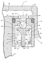
- FIG. 2 is an enlarged vertical sectional view of the pressure regulating valve.
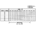
- FIG. 3 is a test data table showing the relationship between the taper angle of the valve seat, the flow rate of fuel flowing through the high pressure port, and whether or not abnormal noise is generated.
- a fuel supply module M for supplying the fuel in the fuel tank T to the fuel injection valve I of the engine is attached to the ceiling wall 1 of the fuel tank T mounted on the motorcycle.
- the fuel supply module M includes an attachment base member 2, an electric pump Ep arranged directly below the attachment base member 2 with the axial direction directed up and down, and an upper pump holder formed integrally with the attachment base member 2.
- 3A a lower pump holder 3B for housing and holding the electric pump Ep in cooperation with the mounting base member 2 and a fuel attached to the lower end of the electric pump Ep.
- a strainer 4 for supplying the fuel in the fuel tank T to the fuel injection valve I of the engine is attached to the ceiling wall 1 of the fuel tank T mounted on the motorcycle.
- the fuel supply module M includes an attachment base member 2, an electric pump Ep arranged directly below the attachment base member 2 with the axial direction directed up and down, and an upper pump holder formed integrally with the attachment base member 2.
- 3A a lower pump holder 3B for housing and holding the electric pump Ep in cooperation with the
- the ceiling wall 1 of the fuel tank T is provided with an opening 5 for inserting the electric pump Ep therein, and a mounting ring 6 surrounding the opening 5 is fixed.
- a plurality of mounting bolts 7, 7... Projecting from the upper surface of the mounting ring 6 are fixed.
- the mounting base member 2 is overlaid on the upper surface of the mounting ring 6 so as to close the opening 5, and includes a plurality of mounting bolts 7, 7... And a plurality of nuts 8, 8. It is fixed to the mounting ring 6. At that time, an annular seal member 9 for sealing the opening 5 is interposed between the mounting base member 2 and the ceiling wall 1 of the fuel tank T.
- the attachment base member 2 is made of synthetic resin, and a fuel take-out pipe 12 protruding in the horizontal direction outside the fuel tank T is integrally formed on the upper portion of the attachment base member 2. Is connected to a fuel supply conduit 33 connected to the fuel injection valve I of the engine.
- the upper pump holder 3A formed integrally with the lower surface of the mounting base member 2 has a cylindrical shape so as to protrude into the fuel tank T and fit into the outer peripheral surface of the upper half of the electric pump Ep.
- the lower pump holder 3B is formed into a cylindrical shape with synthetic resin so as to accommodate and hold the lower half of the electric pump Ep.
- the upper and lower pump holders 3A and 3B are formed with locking claws (not shown) at opposite ends thereof, and the pump holders 3A and 3B can be separated from each other by the engagement of the locking claws.
- the electric pump Ep is coupled and held between the upper pump holder 3A and the lower pump holder 3B.
- the electric pump Ep is composed of an electric motor E with the rotor 20 oriented in the vertical direction and a fuel pump P driven by the electric motor E.
- the electric motor E is coupled to a cylindrical stator 17 having a plurality of magnets 17a arranged in the circumferential direction on the inner circumferential surface, an upper bearing bracket 18 that is caulked to the upper end of the stator 17, and a lower end thereof.
- the lower bearing bracket 19 and the rotor 20 on which the rotor shaft 20a is supported by the upper and lower bearing brackets 18 and 19 are configured.
- the fuel pump P includes a pump case 23 that is caulked to the stator 17 together with the lower bearing bracket 19 so as to define a pump chamber 22 between the lower surface of the lower bearing bracket 19 and a rotor shaft that is rotatably accommodated in the pump chamber 22.
- the pump impeller 24 connected to the lower end of 20a is configured in a Wesco type.
- the pump case 23 is provided with a suction port 25 that opens into the pump chamber 22, and the fuel strainer 4 disposed at the bottom of the fuel tank T is connected to the suction port 25. It is attached to a support shaft 26 projecting from the lower surface of the case 23.
- the lower bearing bracket 19 is provided with a discharge port 27 that communicates between the pump chamber 22 and the stator 17.
- the upper bearing bracket 18 is integrally formed with a fuel discharge pipe 30 that protrudes upward and has a final discharge port 34 that communicates with the interior of the stator 17, and in which the fuel flows backward to the final discharge port 34.
- a check valve 31 is provided to prevent this.
- the fuel discharge pipe 30 is fitted into a fitting hole 29 opened on the lower surface of the mounting base member 2 via a seal member 32.
- the mounting base member 2 is formed with a series of L-shaped fuel passages 28 that run inside the fuel take-out pipe 12 and the fuel discharge pipe 30 and a pressure regulation path 35 that branches from the middle of the fuel passage 28.
- a pressure adjusting valve R for adjusting the pressure in the fuel passage 28 to a predetermined pressure suitable for fuel injection from the fuel injection valve I is connected to the pressure adjusting path 35.
- the pressure regulating valve R includes a cylindrical valve housing 36 with an end wall 36 a formed separately from the mounting base member 2, and an annular recess 52 on the outer periphery of the valve housing 36.
- An annular seal member 53 is attached to the.
- the valve housing 36 has a fitting hole 46 provided on the bottom surface of the mounting base member 2 so as to open on the lower surface thereof, with the end wall 36a facing upward and the seal member 53 in close contact with the inner peripheral surface of the fitting hole 46. Press fit to install.
- the valve housing 36 may be made of metal (for example, stainless steel) or synthetic resin, but is preferably made of metal.
- the end wall 36 a of the valve housing 36 is formed with a high-pressure port 37 extending from the pressure adjusting path 35 by bending at a substantially right angle and a conical valve seat 38 connected to the inner end of the high-pressure port 37.
- the taper angle ⁇ of the valve seat 38 is set to 20 ° to 36 °.
- a spherical valve body 39 made of a steel ball that can be seated on the valve seat 38, a valve retainer 41 that supports the spherical valve body 39 on the opposite side of the valve seat 38, and the valve
- a pressure regulating spring 40 that energizes the spherical valve body 39 with a predetermined set load in the seating direction with the valve seat 38 via the retainer 41 is accommodated, and supports a fixed end 40a of the pressure regulating spring 40,
- a guide member 43 that slidably supports the valve retainer 41 in the opening and closing direction of the spherical valve body 39 is press-fitted and fixed to the inner peripheral surface of the valve housing 36.
- the valve retainer 41 is formed in an umbrella shape by a flange 41a having a diameter larger than that of the spherical valve body 39 and a stem 41b protruding from the back surface of the flange 41a, and a part of the spherical valve body 39 is formed on the end surface of the flange 41a. Is provided with a spherical recess 55 that is rotatably engaged.
- the stem 41b has a conical base 41ba connected to the back surface of the flange 41a.
- the back surface of the flange 41a has an annular shape that supports the movable end portion 40b of the flat pressure regulating spring 40 surrounding the base 41ba.
- the spring receiving surface 56 is formed.
- the valve retainer 41 is preferably made of synthetic resin.
- the guide member 43 includes a cylindrical body 43a that is press-fitted and fixed to the inner peripheral surface of the valve housing 36, and a bottom wall 43b that is integrally connected to the lower end of the body 43a.
- the bottom wall 43b is provided with a guide hole 44 located in the center and a plurality of open ports 57, 57... Arranged so as to surround the guide hole 44, and the guide hole 44 connects the stem 41b to the spherical valve.
- the open ports 57, 57... Open the interior of the valve housing 36, that is, the valve chamber 42 to the fuel tank T.
- the guide member 43 may be made of metal (for example, brass) or synthetic resin.
- the pressure adjusting spring 40 is constituted by a coil spring, and the movable end 40b of the pressure adjusting spring 40 is supported by the spring receiving surface 56 while being aligned by the conical root 41ba of the stem 41b of the valve retainer 41, and the fixed end 40a. Is supported by the inner surface of the bottom wall 43b while being aligned on the inner peripheral surface of the body 43a of the guide member 43.
- the set load of the pressure regulating spring 40 on the spherical valve body 39 is adjusted by adjusting the depth of press-fitting of the body portion 43a of the guide member 43 into the inner peripheral surface of the valve housing 36.
- the attachment base member 2 is formed with a bag-like recess 45 extending linearly from the pressure adjusting path 35.
- the bag-shaped recess 45 is disposed on an extension line on the downstream end side of the pressure adjusting path 35.
- the fuel discharge pipe 30 is arranged on one side of the upper end surface of the upper bearing bracket 18, and a power supply terminal 47 of the electric motor E is projected on the other side.
- the mounting base member 2 is integrally formed with a power feeding coupler 48 protruding from the upper surface thereof, and a connection terminal 49 in the coupler 48 and the power feeding terminal 47 are connected via a relay conductor 50.
- the lower surface of the pressure regulating valve R is disposed so as to face the upper surface 18a of the upper bearing bracket 18 on which the power supply terminal 47 protrudes, that is, the upper surface of the electric pump Ep, and is discharged from the open ports 57, 57.
- the fuel falls on the upper surface 18 a of the upper bearing bracket 18 around the power supply terminal 47.
- a notch window 51 is provided on the peripheral wall of the upper pump holder 3A.
- the pump impeller 24 is rotationally driven by the rotor shaft 20a.
- the fuel in the fuel tank T is sucked into the pump chamber 22 from the suction port 25 while being filtered by the fuel strainer 4, boosted by the pump impeller 24, and pumped into the stator 17 from the discharge port 27, and the final discharge port 34.
- the fuel injection valve I through the fuel discharge pipe 30 and the fuel take-out pipe 12, that is, the fuel passage 28.
- the pressure of the fuel passage 28, that is, the discharge pressure of the electric pump Ep acts on the spherical valve body 39 of the pressure regulating valve R through the pressure adjusting passage 35. Therefore, when the discharge pressure of the electric pump Ep exceeds a predetermined value, The valve body 39 opens against the set load of the pressure regulating spring 40, and a part of the fuel in the fuel passage 28 flows out to the valve chamber 42 through the pressure regulating path 35 and the high pressure port 37, and further, the opening port 57. , 57... Are discharged into the fuel tank T, and when the pressure in the fuel passage 28 returns to a predetermined value, the spherical valve body 39 is closed again by the set load of the pressure regulating spring 40. Thus, the pressure in the fuel passage 28 is automatically adjusted to a predetermined value, so that the fuel injection pressure from the fuel injection valve I is properly controlled.
- the spherical valve body 39 when the spherical valve body 39 is opened, the high-pressure fuel that has passed through the pressure regulating path 35 is bent substantially at a right angle and flows out to the high-pressure port 37 of the pressure regulating valve R. Since the flow rate of the high-pressure fuel flowing outside the bent portion is higher than the flow rate of the high-pressure fuel flowing inside the bent portion, the flow rate of the high-pressure fuel flowing on both sides of the spherical valve body 39 facing the valve seat 38 is If the spherical valve body 39 vibrates in the diametrical direction of the valve seat 38 due to the height, and the amplitude increases, abnormal noise is generated.
- the taper angle ⁇ of the conical valve seat 38 is set to 20 ° to 36 °, the amplitude of the spherical valve body 39 in the diameter direction of the valve seat 38 is such that no abnormal noise is generated. It can be kept small.
- the taper angle ⁇ of the valve seat 38 is set to be less than 20 °, the spherical valve body 39 bites on the valve seat 38 and cannot be properly opened, resulting in an obstacle to pressure regulation.
- FIG. 3 is a data table obtained by the test, and shows the relationship between the taper angle ⁇ of the valve seat 38, the fuel flow rate flowing through the high pressure port 37, and the presence or absence of abnormal noise.
- 20 L / hour in the actual use area is the fuel flow rate at the high pressure port 37 at high engine load and high rotation
- 40 L / hour in the actual use area is the high pressure port at engine idling.
- 37 is the fuel flow rate.
- the pressure regulating valve R can be arranged so that the high pressure port 37 communicates directly with the fuel passage 28.
Landscapes
- Engineering & Computer Science (AREA)
- Chemical & Material Sciences (AREA)
- Combustion & Propulsion (AREA)
- Mechanical Engineering (AREA)
- General Engineering & Computer Science (AREA)
- Safety Valves (AREA)
- Fuel-Injection Apparatus (AREA)
Abstract
Description
P・・・・・燃料ポンプ
R・・・・・圧力調整弁
θ・・・・・テーパ角度
28・・・・燃料通路
35・・・・調圧路
37・・・・高圧ポート
38・・・・弁座
39・・・・球状弁体
40・・・・調圧ばね
42・・・・弁室
Claims (2)
- 燃料ポンプ(P)の吐出燃料をエンジンの燃料噴射弁(I)に送る燃料通路(28)内の圧力を所定値に調整する圧力調整弁であって,前記燃料通路(28)又はそれに連なる調圧路(35)に連通する高圧ポート(37)と,この高圧ポート(37)に円錐状の弁座(38)を介して連なると共に低圧部に開放される弁室(42)と,この弁室(42)に収容され前記弁座(38)と協働して前記高圧ポート(37)を開閉する球状弁体(39)と,この球状弁体(39)を前記弁座(38)との着座方向に所定のセット荷重で付勢する調圧ばね(40)とを備えるものにおいて,
前記円錐状の弁座(38)のテーパ角度(θ)を20°~36°に設定したことを特徴とする圧力調整弁。 - 請求項1記載の圧力調整弁において,
前記高圧ポート(37)を,これが前記燃料通路(28)又はそれに連なる調圧路(35)から屈曲して延びるように配置したことを特徴とする圧力調整弁。
Priority Applications (1)
| Application Number | Priority Date | Filing Date | Title |
|---|---|---|---|
| CN201480060990.6A CN105745431A (zh) | 2013-11-07 | 2014-09-12 | 调压阀 |
Applications Claiming Priority (2)
| Application Number | Priority Date | Filing Date | Title |
|---|---|---|---|
| JP2013-231240 | 2013-11-07 | ||
| JP2013231240A JP2015090137A (ja) | 2013-11-07 | 2013-11-07 | 圧力調整弁 |
Publications (1)
| Publication Number | Publication Date |
|---|---|
| WO2015068466A1 true WO2015068466A1 (ja) | 2015-05-14 |
Family
ID=53041249
Family Applications (1)
| Application Number | Title | Priority Date | Filing Date |
|---|---|---|---|
| PCT/JP2014/074178 Ceased WO2015068466A1 (ja) | 2013-11-07 | 2014-09-12 | 圧力調整弁 |
Country Status (3)
| Country | Link |
|---|---|
| JP (1) | JP2015090137A (ja) |
| CN (1) | CN105745431A (ja) |
| WO (1) | WO2015068466A1 (ja) |
Families Citing this family (1)
| Publication number | Priority date | Publication date | Assignee | Title |
|---|---|---|---|---|
| WO2025225250A1 (ja) * | 2024-04-23 | 2025-10-30 | 株式会社パイオラックス | 弁装置 |
Citations (3)
| Publication number | Priority date | Publication date | Assignee | Title |
|---|---|---|---|---|
| JP2003185041A (ja) * | 2001-12-14 | 2003-07-03 | Bosch Automotive Systems Corp | 圧力リリーフ弁 |
| JP2007291867A (ja) * | 2006-04-21 | 2007-11-08 | Keihin Corp | 燃料供給モジュール |
| JP2008057721A (ja) * | 2006-09-01 | 2008-03-13 | Aisan Ind Co Ltd | 圧力調整弁 |
Family Cites Families (5)
| Publication number | Priority date | Publication date | Assignee | Title |
|---|---|---|---|---|
| DE3462169D1 (en) * | 1983-06-29 | 1987-02-26 | Bbc Brown Boveri & Cie | Axial turbine for a turbo charger |
| US5598823A (en) * | 1995-06-05 | 1997-02-04 | Ford Motor Company | Pressure responsive shut-off device |
| US5649561A (en) * | 1996-05-03 | 1997-07-22 | Parr Manufacturing, Inc. | Fuel filter and pressure regulator system |
| JP5358043B2 (ja) * | 2007-01-11 | 2013-12-04 | 株式会社ミツバ | 圧力制御装置 |
| KR100981086B1 (ko) * | 2008-08-13 | 2010-09-08 | 인지컨트롤스 주식회사 | 차량의 연료시스템용 압력조절기 |
-
2013
- 2013-11-07 JP JP2013231240A patent/JP2015090137A/ja active Pending
-
2014
- 2014-09-12 WO PCT/JP2014/074178 patent/WO2015068466A1/ja not_active Ceased
- 2014-09-12 CN CN201480060990.6A patent/CN105745431A/zh active Pending
Patent Citations (3)
| Publication number | Priority date | Publication date | Assignee | Title |
|---|---|---|---|---|
| JP2003185041A (ja) * | 2001-12-14 | 2003-07-03 | Bosch Automotive Systems Corp | 圧力リリーフ弁 |
| JP2007291867A (ja) * | 2006-04-21 | 2007-11-08 | Keihin Corp | 燃料供給モジュール |
| JP2008057721A (ja) * | 2006-09-01 | 2008-03-13 | Aisan Ind Co Ltd | 圧力調整弁 |
Also Published As
| Publication number | Publication date |
|---|---|
| JP2015090137A (ja) | 2015-05-11 |
| CN105745431A (zh) | 2016-07-06 |
Similar Documents
| Publication | Publication Date | Title |
|---|---|---|
| JP4914701B2 (ja) | 圧力調整弁 | |
| US5778926A (en) | Pressure regulating valve and fuel supply system using the same | |
| CN101970850B (zh) | 燃料供给模块 | |
| WO2007123037A1 (ja) | 燃料供給モジュール | |
| JP5962694B2 (ja) | 燃料蒸気漏れ検出装置 | |
| JP4923123B2 (ja) | 燃料供給装置 | |
| JP5189998B2 (ja) | 燃料供給装置 | |
| JP2008184954A (ja) | 燃料ポンプモジュール | |
| US9574530B2 (en) | Fuel pump module and method of manufacturing the same | |
| US9567953B2 (en) | Fuel pump module | |
| JP6391084B2 (ja) | 圧力調整弁装置 | |
| JP2009097344A (ja) | 燃料供給装置 | |
| WO2015068466A1 (ja) | 圧力調整弁 | |
| JP2007291866A (ja) | 電動ポンプ保持装置 | |
| JP4922868B2 (ja) | 燃料供給装置 | |
| JP5248312B2 (ja) | 燃料供給装置 | |
| JP2008138786A (ja) | 弁装置 | |
| JP4871400B2 (ja) | 燃料供給装置 | |
| JP6793606B2 (ja) | 圧力制御装置、及び燃料供給装置 | |
| JP2010144594A (ja) | 燃料ポンプ | |
| JP2009235941A (ja) | 燃料供給モジュール | |
| JP4700549B2 (ja) | 燃料供給モジュール | |
| JP2014152726A (ja) | 燃料ポンプモジュール | |
| JPWO2006115014A1 (ja) | 燃料供給装置 | |
| JP2007291863A5 (ja) |
Legal Events
| Date | Code | Title | Description |
|---|---|---|---|
| 121 | Ep: the epo has been informed by wipo that ep was designated in this application |
Ref document number: 14860379 Country of ref document: EP Kind code of ref document: A1 |
|
| NENP | Non-entry into the national phase |
Ref country code: DE |
|
| REG | Reference to national code |
Ref country code: BR Ref legal event code: B01A Ref document number: 112016009129 Country of ref document: BR |
|
| WWE | Wipo information: entry into national phase |
Ref document number: IDP00201603650 Country of ref document: ID |
|
| 122 | Ep: pct application non-entry in european phase |
Ref document number: 14860379 Country of ref document: EP Kind code of ref document: A1 |
|
| ENP | Entry into the national phase |
Ref document number: 112016009129 Country of ref document: BR Kind code of ref document: A2 Effective date: 20160425 |