WO2015068273A1 - ガスシールドアーク溶接用フラックス入りワイヤ及びそのワイヤを用いた極低温用鋼の溶接方法 - Google Patents
ガスシールドアーク溶接用フラックス入りワイヤ及びそのワイヤを用いた極低温用鋼の溶接方法 Download PDFInfo
- Publication number
- WO2015068273A1 WO2015068273A1 PCT/JP2013/080284 JP2013080284W WO2015068273A1 WO 2015068273 A1 WO2015068273 A1 WO 2015068273A1 JP 2013080284 W JP2013080284 W JP 2013080284W WO 2015068273 A1 WO2015068273 A1 WO 2015068273A1
- Authority
- WO
- WIPO (PCT)
- Prior art keywords
- flux
- cored wire
- content
- mass
- welding
- Prior art date
- Legal status (The legal status is an assumption and is not a legal conclusion. Google has not performed a legal analysis and makes no representation as to the accuracy of the status listed.)
- Ceased
Links
Images




Classifications
-
- B—PERFORMING OPERATIONS; TRANSPORTING
- B23—MACHINE TOOLS; METAL-WORKING NOT OTHERWISE PROVIDED FOR
- B23K—SOLDERING OR UNSOLDERING; WELDING; CLADDING OR PLATING BY SOLDERING OR WELDING; CUTTING BY APPLYING HEAT LOCALLY, e.g. FLAME CUTTING; WORKING BY LASER BEAM
- B23K35/00—Rods, electrodes, materials, or media, for use in soldering, welding, or cutting
- B23K35/22—Rods, electrodes, materials, or media, for use in soldering, welding, or cutting characterised by the composition or nature of the material
- B23K35/36—Selection of non-metallic compositions, e.g. coatings or fluxes; Selection of soldering or welding materials, conjoint with selection of non-metallic compositions, both selections being of interest
-
- B—PERFORMING OPERATIONS; TRANSPORTING
- B23—MACHINE TOOLS; METAL-WORKING NOT OTHERWISE PROVIDED FOR
- B23K—SOLDERING OR UNSOLDERING; WELDING; CLADDING OR PLATING BY SOLDERING OR WELDING; CUTTING BY APPLYING HEAT LOCALLY, e.g. FLAME CUTTING; WORKING BY LASER BEAM
- B23K35/00—Rods, electrodes, materials, or media, for use in soldering, welding, or cutting
- B23K35/02—Rods, electrodes, materials, or media, for use in soldering, welding, or cutting characterised by mechanical features, e.g. shape
- B23K35/0255—Rods, electrodes, materials, or media, for use in soldering, welding, or cutting characterised by mechanical features, e.g. shape for use in welding
-
- B—PERFORMING OPERATIONS; TRANSPORTING
- B23—MACHINE TOOLS; METAL-WORKING NOT OTHERWISE PROVIDED FOR
- B23K—SOLDERING OR UNSOLDERING; WELDING; CLADDING OR PLATING BY SOLDERING OR WELDING; CUTTING BY APPLYING HEAT LOCALLY, e.g. FLAME CUTTING; WORKING BY LASER BEAM
- B23K35/00—Rods, electrodes, materials, or media, for use in soldering, welding, or cutting
- B23K35/02—Rods, electrodes, materials, or media, for use in soldering, welding, or cutting characterised by mechanical features, e.g. shape
- B23K35/0255—Rods, electrodes, materials, or media, for use in soldering, welding, or cutting characterised by mechanical features, e.g. shape for use in welding
- B23K35/0261—Rods, electrodes or wires
-
- B—PERFORMING OPERATIONS; TRANSPORTING
- B23—MACHINE TOOLS; METAL-WORKING NOT OTHERWISE PROVIDED FOR
- B23K—SOLDERING OR UNSOLDERING; WELDING; CLADDING OR PLATING BY SOLDERING OR WELDING; CUTTING BY APPLYING HEAT LOCALLY, e.g. FLAME CUTTING; WORKING BY LASER BEAM
- B23K35/00—Rods, electrodes, materials, or media, for use in soldering, welding, or cutting
- B23K35/02—Rods, electrodes, materials, or media, for use in soldering, welding, or cutting characterised by mechanical features, e.g. shape
- B23K35/0255—Rods, electrodes, materials, or media, for use in soldering, welding, or cutting characterised by mechanical features, e.g. shape for use in welding
- B23K35/0261—Rods, electrodes or wires
- B23K35/0266—Rods, electrodes or wires flux-cored
-
- B—PERFORMING OPERATIONS; TRANSPORTING
- B23—MACHINE TOOLS; METAL-WORKING NOT OTHERWISE PROVIDED FOR
- B23K—SOLDERING OR UNSOLDERING; WELDING; CLADDING OR PLATING BY SOLDERING OR WELDING; CUTTING BY APPLYING HEAT LOCALLY, e.g. FLAME CUTTING; WORKING BY LASER BEAM
- B23K35/00—Rods, electrodes, materials, or media, for use in soldering, welding, or cutting
- B23K35/22—Rods, electrodes, materials, or media, for use in soldering, welding, or cutting characterised by the composition or nature of the material
- B23K35/24—Selection of soldering or welding materials proper
- B23K35/30—Selection of soldering or welding materials proper with the principal constituent melting at less than 1550°C
- B23K35/3053—Fe as the principal constituent
- B23K35/3066—Fe as the principal constituent with Ni as next major constituent
-
- B—PERFORMING OPERATIONS; TRANSPORTING
- B23—MACHINE TOOLS; METAL-WORKING NOT OTHERWISE PROVIDED FOR
- B23K—SOLDERING OR UNSOLDERING; WELDING; CLADDING OR PLATING BY SOLDERING OR WELDING; CUTTING BY APPLYING HEAT LOCALLY, e.g. FLAME CUTTING; WORKING BY LASER BEAM
- B23K35/00—Rods, electrodes, materials, or media, for use in soldering, welding, or cutting
- B23K35/22—Rods, electrodes, materials, or media, for use in soldering, welding, or cutting characterised by the composition or nature of the material
- B23K35/34—Rods, electrodes, materials, or media, for use in soldering, welding, or cutting characterised by the composition or nature of the material comprising compounds which yield metals when heated
-
- B—PERFORMING OPERATIONS; TRANSPORTING
- B23—MACHINE TOOLS; METAL-WORKING NOT OTHERWISE PROVIDED FOR
- B23K—SOLDERING OR UNSOLDERING; WELDING; CLADDING OR PLATING BY SOLDERING OR WELDING; CUTTING BY APPLYING HEAT LOCALLY, e.g. FLAME CUTTING; WORKING BY LASER BEAM
- B23K35/00—Rods, electrodes, materials, or media, for use in soldering, welding, or cutting
- B23K35/22—Rods, electrodes, materials, or media, for use in soldering, welding, or cutting characterised by the composition or nature of the material
- B23K35/36—Selection of non-metallic compositions, e.g. coatings or fluxes; Selection of soldering or welding materials, conjoint with selection of non-metallic compositions, both selections being of interest
- B23K35/3601—Selection of non-metallic compositions, e.g. coatings or fluxes; Selection of soldering or welding materials, conjoint with selection of non-metallic compositions, both selections being of interest with inorganic compounds as principal constituents
- B23K35/3602—Carbonates, basic oxides or hydroxides
-
- B—PERFORMING OPERATIONS; TRANSPORTING
- B23—MACHINE TOOLS; METAL-WORKING NOT OTHERWISE PROVIDED FOR
- B23K—SOLDERING OR UNSOLDERING; WELDING; CLADDING OR PLATING BY SOLDERING OR WELDING; CUTTING BY APPLYING HEAT LOCALLY, e.g. FLAME CUTTING; WORKING BY LASER BEAM
- B23K35/00—Rods, electrodes, materials, or media, for use in soldering, welding, or cutting
- B23K35/22—Rods, electrodes, materials, or media, for use in soldering, welding, or cutting characterised by the composition or nature of the material
- B23K35/36—Selection of non-metallic compositions, e.g. coatings or fluxes; Selection of soldering or welding materials, conjoint with selection of non-metallic compositions, both selections being of interest
- B23K35/3601—Selection of non-metallic compositions, e.g. coatings or fluxes; Selection of soldering or welding materials, conjoint with selection of non-metallic compositions, both selections being of interest with inorganic compounds as principal constituents
- B23K35/3603—Halide salts
-
- B—PERFORMING OPERATIONS; TRANSPORTING
- B23—MACHINE TOOLS; METAL-WORKING NOT OTHERWISE PROVIDED FOR
- B23K—SOLDERING OR UNSOLDERING; WELDING; CLADDING OR PLATING BY SOLDERING OR WELDING; CUTTING BY APPLYING HEAT LOCALLY, e.g. FLAME CUTTING; WORKING BY LASER BEAM
- B23K35/00—Rods, electrodes, materials, or media, for use in soldering, welding, or cutting
- B23K35/22—Rods, electrodes, materials, or media, for use in soldering, welding, or cutting characterised by the composition or nature of the material
- B23K35/36—Selection of non-metallic compositions, e.g. coatings or fluxes; Selection of soldering or welding materials, conjoint with selection of non-metallic compositions, both selections being of interest
- B23K35/3601—Selection of non-metallic compositions, e.g. coatings or fluxes; Selection of soldering or welding materials, conjoint with selection of non-metallic compositions, both selections being of interest with inorganic compounds as principal constituents
- B23K35/3603—Halide salts
- B23K35/3605—Fluorides
Definitions
- the present invention relates to a flux-cored wire used for gas shielded arc welding of 6 to 9% Ni steel for cryogenic temperatures used in LNG tanks, chemical plants and the like, and in particular, a weld metal having excellent low temperature toughness can be obtained. Furthermore, the present invention relates to a flux-cored wire for gas shielded arc welding which can further improve the welding construction efficiency and is excellent in low-temperature crack resistance, and a method for welding cryogenic steel using the wire.
- Ni-based alloy welding materials containing 60 to 80% Ni are used because of the necessity of satisfying strict safety, but they contain a large amount of Ni. This welding material is very expensive.
- Ni-base alloy welding materials are prone to weld defects such as poor fusion due to poor molten metal flow, and welding is performed with low heat input to prevent welding defects. There is also a problem with efficiency.
- the weld metal has a very hard martensite structure, which causes a problem of low-temperature cracking. Cold cracking does not occur in Ni-base alloy welding materials whose weld metal structure is austenite, and the preheating work performed to suppress cold cracking is a new issue in reducing welding costs.
- Patent Document 1 discloses a flux-cored wire using a Ni-based alloy material as an outer skin, but the Ni content is 60 to 70%, and the cost of the welding material cannot be reduced.
- Patent Document 2 discloses a welding material having a Ni content of 7.5 to 12.0%. However, since the welding method is TIG welding with low welding execution efficiency, the welding execution efficiency is not improved.
- Patent Document 3 discloses a wire that is a welding material having an Ni content of 8 to 13%, achieves a reduction in melt cost, and has excellent welding efficiency by applying submerged arc welding.
- the oxygen content of the obtained weld metal is as high as 250 ppm, and accordingly, the absorbed energy at ⁇ 196 ° C. is low, and sufficient low temperature toughness is not ensured. In addition, no investigation has been made on the low temperature cracking which causes a problem with this Ni amount.
- Non-Patent Document 1 uses a solid wire made of iron alloy with Ni reduced to about 10% and uses MIG welding with 100% Ar shielding gas to obtain a low oxygen weld metal similar to TIG welding. Techniques are disclosed. In this technique, the amount of P and S in the wire is remarkably reduced, so that toughness is ensured. However, in our experiments, in the weld metal obtained by the method of Non-Patent Document 1, Has a disadvantage that it has a large amount of diffusible hydrogen and poor cold cracking resistance. Further, since the wire described in Non-Patent Document 1 is a solid wire in which Rem addition is essential, there is a drawback that spattering is severe and welding workability is poor at the time of welding.
- the activity contained in the shielding gas Oxygen entering the weld metal from the gas becomes a problem.
- the shielding gas generally Ar-10-30% CO 2 (that is, in CO 2 of 10-30% in volume fraction, a mixed gas of balance Ar), 100% CO 2, or Ar, -2% O 2 or the like is used, and the gas contains 2% or more of CO 2 or O 2 which is an active gas. The reason is that the inert gas alone makes the arc unstable and a sound weld metal free of welding defects or the like cannot be obtained.
- these active gases are ionized by the welding arc, and the ionized oxygen ions enter the weld metal. Therefore, when the active gas is mixed, the amount of oxygen in the weld metal increases. As the amount of oxygen in the weld metal increases, the absorbed energy for ductile fracture decreases. As a welding material for cryogenic steels, welding materials with a Ni content as low as 6-9% Ni steel are difficult to secure the absorbed energy for this ductile fracture. There is a need for a welding method that provides a metal. However, a welding wire capable of obtaining a sound weld metal has not yet been realized by gas shield arc welding using a shield gas with a reduced amount of active gas mixed or using only an inert gas.
- TIG welding In non-consumable electrode type TIG welding, a sound weld metal is obtained and the amount of oxygen in the weld metal is low, but TIG welding has a much lower welding efficiency than consumable electrode type gas shielded arc welding, and welding There is a problem that costs increase.
- the weld metal has a very hard martensite structure, which causes a problem of low temperature cracking.
- preheating work is necessary. Preheating work also causes a decrease in welding efficiency, but the conventional technology has not studied cold cracking resistance at all.
- the present invention applies gas shielded arc welding in which the amount of Ni is reduced to the same level as 6-9% Ni steel, thereby significantly reducing welding material costs and excellent welding efficiency. Even so, it is an object to obtain a weld metal excellent in low temperature toughness of -196 ° C. Furthermore, the present invention provides a flux-cored wire for gas shielded arc welding that requires no preheating work to suppress low temperature cracking or can significantly reduce the preheating work, and a method for welding cryogenic steel using the wire. Is an issue.
- the present inventors have made a slag component composition mainly composed of fluoride in a flux-cored wire in which the amount of Ni is reduced to about 6 to 9% Ni steel, (I) Even in gas shielded arc welding using a pure Ar gas or a mixed gas having a proportion of oxygen in the pure Ar gas of less than 2% as the shielding gas, the arc is stable and the welding is sound and has a low oxygen content. A metal is obtained.
- a steel outer shell containing 6 to 16% of Ni is used to greatly reduce the alloy components filled in the flux and further reduce the oxygen content of the weld metal, and then C, Si, Mn, It was found that excellent Charpy absorbed energy at ⁇ 196 ° C. can be obtained by setting the other alloy elements to optimum compositions for the weld metal obtained by this welding method. Furthermore, it has also been found that the flux-cored wire of the present invention can significantly reduce the diffusible hydrogen of the weld metal. As a result, in welding of 5.5 to 9.5% Ni steel, a weld metal having excellent low temperature toughness is obtained, the welding work efficiency is high, and preheating is performed to suppress low temperature cracking. The present inventors have found a flux-cored wire that can be omitted or simplified, and have further studied based on the knowledge to arrive at the present invention.
- the flux-cored wire according to the first aspect of the present invention is a flux-cored wire in which a flux is filled inside a steel outer sheath, and the flux-cored wire includes CaF 2 which is a metal fluoride.
- the flux-cored wire includes CaF 2 which is a metal fluoride.
- One or more of BaF 2 , SrF 2 , MgF 2 , and LiF are contained, and when the total content is ⁇ , the ⁇ is 2% by mass with respect to the total mass of the flux-cored wire.
- ⁇ 0.0 to 7.0%, containing one or more of metal oxides of Ti oxide, Si oxide, Mg oxide, Al oxide, Zr oxide, and Ca oxide
- the metal carbonates CaCO 3 , BaCO 3 , SrCO 3 , 1 type (s) or 2 or more types of MgCO 3 and Li 2 CO 3 are contained, and the total content is less than 0.6% in terms of mass% with respect to the total mass of the flux-cored wire
- the ratio of the CaF 2 content is 0.90 or more, the ratio of the ⁇ to the ⁇ is 3.0 or more and 15.0 or less, and the content of the Ti oxide is the whole of the flux-cored wire.
- the content of the Si oxide is 0 to 0.4% by mass with respect to the mass, and the content of the Si oxide is 0.2 to 0.5% by mass with respect to the total mass of the flux-cored wire.
- the content is less than 0.20% by mass% with respect to the total mass of the flux-cored wire, and the content of CaCO 3 is less than 0.6% by mass% with respect to the total mass of the flux-cored wire,
- the flack The content of the arc stabilizer in the solder is 0 to 0.5% by mass with respect to the total mass of the flux-cored wire, and the content of iron powder in the flux is relative to the total mass of the flux-cored wire.
- the chemical composition excluding the metal fluoride, the metal oxide, and the metal carbonate is less than 5% by mass, and is expressed by mass% with respect to the total mass of the flux-cored wire: C: 0.003 to 0.00. 040%; Si: 0.05 to 0.40%; Mn: 0.2 to 0.8%; Al: 0.003 to 0.050%; Ni: 6.0 to 16.0%; P: 0 0.02% or less; S: 0.01% or less; Cu: 0 to 0.5%; Cr: 0 to 0.5%; Mo: 0 to 0.5%; V: 0 to 0.2%; Ti : 0 to 0.1%; Nb: 0 to 0.1%; B: 0 to 0.01%; Mg: 0 to 0.6%; REM: 0 to 0 0500%; balance: Fe and impurities; SM defined by the following formula a is 0.3 to 1.0%, and Ceq defined by the following formula b is 0.25 to 0.52.
- the flux-cored wire according to (1) is the flux-cored wire in which the flux is filled inside the steel outer shell containing Ni, and the content of Ni in the steel outer shell However, it may be 6 to 18% by mass% with respect to the total mass of the steel outer shell.
- the content of the REM in the flux-cored wire is 0.0100% or less in mass% with respect to the total mass of the flux-cored wire. May be.
- the CaO content in the flux-cored wire is 0.00% by mass% with respect to the total mass of the flux-cored wire. It may be less than 20%.
- the flux-cored wire according to any one of (1) to (4) above is a weld metal defined in Japanese Industrial Standard JIS Z3111-2005 in gas shielded arc welding using the flux-cored wire.
- the weld metal may have a tensile strength of 660 to 900 MPa.
- the flux-cored wire according to any one of (1) to (5) above may not have a slit-like gap in the steel outer sheath.
- perfluoropolyether oil may be applied to the surface of the steel outer shell.
- a welding method uses a flux-cored wire according to any one of the above (1) to (7) and uses pure Ar gas, Ar and 1 as a shielding gas. Welding is performed using any one of a mixed gas of 5% by volume or less of O 2 or CO 2 , pure He gas, or a mixed gas of He and 1.5% by volume or less of O 2 or CO 2 .
- the plate thickness is 6 to 100 mm
- the Ni content is 5.5 to 9.5% by mass
- the tensile strength is 660.
- pure Ar gas, Ar and 1.5 vol% or less O 2 as a shielding gas. or mixed gas of CO 2
- a flux-cored wire used for welding of a Ni-based low temperature steel containing about 5.5 to 9.5% of Ni the amount of Ni is reduced to the same level as a Ni-based low temperature steel.
- the weld metal of Ni-based low temperature steel is required to have a low temperature toughness of -196 ° C, and it is necessary to reduce the oxygen content of the weld metal in order to ensure the absorbed energy of -196 ° C.
- gas shielded arc welding using an inert gas is conceivable, but the arc became unstable and could not be used because a sound weld metal without welding defects could not be obtained. .
- the former has a problem that the welding material cost is extremely high, and the latter has a problem that the welding operation efficiency is extremely low, and a welding material that achieves both the welding material cost and the welding operation efficiency has not been realized.
- the inventors changed the content of CaF 2 and the metal oxide at various ratios, and further, C, Si, Mn And the content of other alloy elements was changed at various ratios, and the Ni-based low-temperature steel was welded by gas shielded arc welding using an inert gas using the wire thus produced.
- the present invention has been made as a result of the above studies, and the reasons for limiting the technical requirements and preferred aspects of the flux-cored wire of the present embodiment will be sequentially described below.
- “%” means “% by mass” unless otherwise specified, and the content of each component is the sum of the mass% of each component in the steel outer sheath and flux with respect to the total mass of the wire. It shall mean the component content.
- C is an element for improving the strength, and in order to ensure the strength, it is necessary to contain 0.003% or more. In order to improve the strength, the lower limit of the C content may be 0.005%, 0.008%, 0.010%, or 0.013%.
- a weld metal containing 6 to 16% Ni has a hard martensite structure. The influence of C on the hardness of martensite is very large. If the C content exceeds 0.040%, the weld metal is extremely hardened and the toughness is greatly reduced. %. In order to ensure toughness stably, the upper limit of the C content may be 0.035% or 0.030%.
- Si is an element necessary for improving the cleanliness of the weld metal and suppressing the occurrence of weld defects such as blow holes. In order to obtain these effects, a content of 0.05% or more is necessary. In order to further prevent the occurrence of welding defects, the lower limit of the Si content may be 0.09% or 0.14%.
- Si is easily segregated microscopically, and when the Si content exceeds 0.40%, significant embrittlement occurs in the segregated portion. To do.
- the upper limit of Si content as 0.35% or 0.30%.
- Mn is an element necessary for improving the cleanliness of the weld metal and further degrading S and improving toughness by forming MnS. In order to acquire the effect, it is necessary to contain 0.2% or more. In order to further improve toughness, the lower limit of the Mn content may be 0.3%, 0.35%, or 0.4%. On the other hand, in a weld metal containing 6 to 16% of Ni, Mn tends to segregate microscopically, and if the Mn content exceeds 0.8%, significant embrittlement occurs in the segregated portion, so this is the upper limit. . Moreover, in order to ensure the toughness of a weld metal stably, it is good also considering the upper limit of Mn content as 0.7%, 0.6%, or 0.5%.
- P 0.02% or less
- P is an impurity element and needs to be reduced as much as possible in order to deteriorate toughness.
- the P content is limited to 0.02% or less.
- the upper limit of the P content may be 0.015%, 0.01%, 0.008%, or 0.006%.
- the lower limit of the P content is 0%.
- S is an impurity element, it is preferably reduced as much as possible because it significantly deteriorates toughness.
- the S content is limited to 0.01% or less as a range in which an adverse effect on toughness can be tolerated.
- the upper limit of the S content may be 0.008%, 0.006%, 0.004%, or 0.003%.
- the lower limit of the S content is 0%.
- Al 0.003 to 0.050%
- Al is a deoxidizing element and, like Si and Mn, is effective in improving cleanliness, and is contained in an amount of 0.003% or more in order to exhibit the effect.
- the content exceeds 0.050%, nitrides and oxides are formed and the toughness of the weld metal is inhibited, so this is the upper limit.
- the lower limit of the Al content may be 0.005%, 0.007%, 0.009%, or 0.011%.
- the upper limit of the Al content may be 0.040%, 0.035%, 0.030%, or 0.025%.
- Ni is the only element that can improve toughness regardless of the structure and components by solid solution toughening (the effect of increasing toughness by solid solution), and is an essential element to ensure low temperature toughness of -196 ° C in particular. .
- the Ni content needs to be 6.0% or more.
- the upper limit of the Ni content may be limited to 14% or 12%.
- the lower limit of the Ni content may be 6.5%, 7.0%, 7.5%, or even 8.0%.
- Ni may be added to the weld metal mainly from the steel outer shell.
- the metal powder added as a flux has a thin oxide layer, which becomes an oxygen source for the weld metal.
- Ni may be mainly contained in the steel outer shell.
- Ni content may be made to contain 6.0% or more by mass% with respect to the mass of steel outer casings in steel outer casing.
- the upper limit of the Ni content of the steel outer shell may be 18% so that the total mass of the wire is 16% or less.
- the upper limit of the Ni content of the steel outer shell may be 17% or 16%. Since the melting point of the Ni alloy is lower than the melting point of the mild steel, if the Ni alloy is used as the outer shell, the difference between the melting points of the outer shell and the flux increases. As a result, the flux is stabilized as a core, so that the droplet transfer is more stable. As a relative comparison, the Ni alloy steel outer skin reduces the oxygen content of the weld metal and increases the low temperature toughness.
- each element of Cu, Cr, Mo, V, Ti, Nb, B, Mg, and REM can be included as one or more selected elements.
- Cu has the effect of improving the strength of the weld metal when plated on the outer surface of the wire and when contained in the flux as a simple substance or an alloy.
- the lower limit of the Cu content is 0%, but Cu may be contained. In this case, if the Cu content exceeds 0.5%, the toughness decreases, so the Cu content is set to 0.5% or less. In order to improve toughness, the upper limit of the Cu content may be 0.3%, 0.2%, or 0.1%.
- Cr 0-0.5%
- Cr is an element effective for increasing the strength of the weld metal.
- the lower limit of the Cr content is 0%, but when Cr is added, if the Cr content exceeds 0.5%, the toughness decreases, so the Cr content is 0.5% or less.
- the upper limit of the Cr content may be 0.3%, 0.2%, or 0.1%.
- the lower limit of the Cr content may be 0.01%.
- Mo is an element effective for increasing the strength of the weld metal by precipitation strengthening.
- the lower limit of the Mo content is 0%, but when Mo is added, the toughness decreases when the Mo content exceeds 0.5%, so the Mo content is 0.5% or less.
- the upper limit of the Mo content may be 0.3%, 0.2%, or 0.1%.
- the lower limit of the Mo content may be 0.01%.
- V is an element effective for increasing the strength of the weld metal by precipitation strengthening.
- the lower limit of the V content is 0%.
- the toughness decreases when the V content exceeds 0.2%. Therefore, the V content when V is contained is 0.2%.
- the upper limit of the V content may be 0.15%, 0.1%, or 0.05%.
- the lower limit of the V content may be 0.01%.
- Ti is effective in fixing solid solution N and mitigating the adverse effect on toughness. It is also effective as a deoxidizing element and has the effect of reducing the amount of O in the weld metal.
- the lower limit of the Ti content is 0%, but when Ti is added, if the Ti content exceeds 0.1% and excessive, carbides are generated and the toughness is deteriorated.
- the Ti content is 0.1% or less.
- the upper limit of the Ti content may be 0.06%, 0.04%, or 0.02%.
- the lower limit of the Ti content may be 0.005%.
- Nb 0 to 0.1%)
- the lower limit of the Nb content is 0%.
- the Nb content when Nb is contained is 0.1% or less.
- the upper limit of the Ti content may be 0.06%, 0.04%, or 0.02%.
- the lower limit of the Nb content may be 0.002%.
- B 0-0.01%)
- B 0-0.01%
- B in the weld metal becomes excessive and coarse BN or Fe 23 (C, B )
- the B content in the case of containing B is set to 0.01% or less.
- the upper limit of the B content may be 0.006%, 0.004%, or 0.002%.
- the lower limit of the B content may be 0.0003%.
- Mg is a strong deoxidizing element, reduces oxygen in the weld metal, and is effective in improving toughness.
- the lower limit of the Mg content is 0%.
- Mg content is 0.6% or less.
- the upper limit of the Mg content may be 0.4%, 0.2%, or 0.1%.
- the lower limit of the Mg content may be 0.05%.
- the lower limit of the REM content is 0%. Even when it is added, the effective REM content that reduces spatter and stabilizes the arc is 0.0500% or less.
- the upper limit of the REM content may be 0.0300%, 0.0200%, 0.0100%, 0.0050%, or 0.0010%.
- each element is contained as described above as an alloy component or a metal deoxidation component.
- Si and Mn represented by the following formula 1 are used.
- the total content SM must be 0.3 to 1.0%.
- SM [Si] + [Mn] (Formula 1)
- the elements with [] indicate the content (% by mass) of each element.
- the flux-cored wire of this embodiment is a gas shielded arc in which pure Ar or pure He is used as a shielding gas, or a mixed gas in which the proportion of O 2 or CO 2 in Ar or He is less than 2% by volume is used as a shielding gas.
- the lower limit of SM may be set to 0.35% or 0.4%.
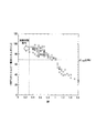
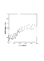
- FIGS. 1 and 2 show a prototype of a flux-cored wire that satisfies the requirements of the present invention except that the SM value is different, and uses the wire to perform welding in the same manner as in the examples described later.
- a test piece was prepared, and the relationship between the Charpy absorbed energy of ⁇ 196 ° C. obtained using the test piece and the SM of the wire is shown. From FIG.
- the wire added with Si and Mn so that the SM was 0.3 to 1.0 had a Charpy absorbed energy of ⁇ 196 ° C. of 50 J or more. From FIG. 2, it was found that the wire added with Si and Mn so that the SM was 0.3 to 1.0 had a Charpy absorbed energy of ⁇ 196 ° C. of 69 J or more.
- the upper limit of SM may be 0.9%, 0.8%, 0.75%, or 0.70% in order to stably secure 50 J or more.
- the upper limit of SM may be set to 0.9%, 0.8%, 0.75%, or 0.70% in order to ensure 69 J or more stably.
- the tensile strength of the weld metal is improved, but on the other hand, the toughness is lowered and the weld cracking sensitivity is increased. Therefore, measures for suppressing low temperature cracking are required.
- the value of Ceq is less than 0.25%, the target strength (tensile strength) of 660 MPa or more cannot be satisfied in the weld metal.
- the value of Ceq exceeds 0.52%, the tensile strength of the weld metal becomes excessive, and the toughness of the weld metal decreases. Therefore, the range of Ceq is set to 0.25 to 0.52%.
- the lower limit of Ceq may be 0.29%, 0.33%, or 0.37%.
- the upper limit of Ceq may be 0.49%, 0.46%, or 0.43%.
- the content of elements contained as the above alloy components or metal deoxidation components does not include the content when these elements are contained as metal fluorides, metal oxides, and metal carbonates. Further, these elements are not necessarily pure substances (impurities can be contained), and there is no problem even if they are contained in the form of alloys such as Fe—Mn and Cu—Ni. In addition, since these elements have the same effect regardless of whether they are contained in the steel skin or as a flux, they can be contained in either the steel skin or the flux.
- a flux-cored wire is used, and a metal fluoride mainly composed of CaF 2 is used as a flux component, thereby enabling stable welding even in gas shield arc welding using an inert gas. Since metal fluoride has low electrical conductivity, the steel sheath melts under an arc, but the flux inside the wire does not completely melt and remains like a core, and the core of the flux is like a whip. Enter the molten pool straight without shaking. At this time, since the molten steel outer shell moves to the molten pool along the core of the flux, stable welding is possible.
- the ⁇ is 2.0. or more%, and the ratio of the content of CaF 2 [CaF 2] with respect to the ⁇ ([CaF 2] / ⁇ ) has to be contained such that 0.90 or more.
- a higher CaF 2 content is preferred, and the lower limit of this ratio may be 0.93, 0.96, 0.98 or 0.99. There is no problem even if this ratio is 1.0 and only CaF 2 is used.
- the total amount ⁇ of metal fluoride is less than 2.0%, a sufficient amount of the flux core does not remain at the time of welding, so that welding becomes unstable.
- the total amount ⁇ of the metal fluoride exceeds 7.0%, welding fume is excessively generated, and welding becomes unstable.
- the lower limit of the total amount ⁇ of metal fluoride is 2.2%, 2.4%, 2.6%, 2 to ensure a more stable weldability. It may be 8%, 3.0%, 3.2%, or 3.4%, and the upper limit of the total amount ⁇ of metal fluoride is 6.5%, 6.0%, 5.5%, or 5. It may be 0%.
- the metal fluoride in addition to CaF 2 , one or more of BaF 2 , SrF 2 , MgF 2 , and LiF can be contained as necessary. From the viewpoint of suppression, the ratio of the content of CaF 2 to the total amount of CaF 2 , BaF 2 , SrF 2 , MgF 2 , and LiF must be 0.90 or more. If it is less than 0.90, the arc stability is lowered. A higher proportion of CaF 2 is desirable, and may be 0.93% or more, 0.96% or more, 0.98% or more, or 0.99%. There is no problem with 100% CaF 2 .
- the metal fluoride has an action of reducing the amount of diffusible hydrogen in the weld metal.
- a weld metal containing 6 to 16% Ni has a hard martensite structure. Therefore, preheating work is required to suppress cold cracking, but metal fluoride can reduce the amount of diffusible hydrogen in the weld metal, so the preheating necessary to suppress cold cracking is omitted or simplified. Enables welding.
- metal fluoride acts to reduce the amount of diffusible hydrogen
- coated arc welding rods and the like but there has been no detailed study of reducing diffusible hydrogen with a flux-cored wire.
- the optimum form for reducing diffusible hydrogen has been found in consideration of other flux components, mechanical properties of the weld metal, welding workability, and the like.
- metal fluoride reduces diffusible hydrogen is that metal fluoride is decomposed by the welding arc and the generated fluorine is combined with hydrogen and dissipated into the atmosphere as HF gas, or in the weld metal as it is. This is probably because hydrogen was fixed as HF.
- TiO 2 (TiO 2 : 0 to 0.4%) TiO 2, by reducing the amount of oxygen in the weld metal, in order to improve the low temperature toughness, TiO 2 is more preferable that as much as possible reduced. For this reason, the lower limit of TiO 2 is set to 0%. On the other hand, in order to improve bead moldability, slag peelability and arc stability, it is preferable to add TiO 2 . For this reason, the lower limit of the TiO 2 content may be 0.05%, 0.1%, 0.13%, 0.16, or 0.19%. If the TiO 2 content exceeds 0.4%, oxygen contained in TiO 2 enters the molten pool, increasing the amount of oxygen in the weld metal and reducing the absorbed energy of ductile fracture.
- the upper limit of the TiO 2 content may be set to 0.35%, 0.31, 0.27%, or 0.24%.
- the upper limit of the TiO 2 content may be 0.2%, 0.15%, 0.12%, or 0.09%.
- SiO 2 is necessary for adjusting the slag shape and facilitating slag peeling after welding.
- the SiO 2 content needs to be 0.2% or more.
- the lower limit of the SiO 2 content may be 0.23%, 0.26, or 0.29%.
- oxygen contained in SiO 2 enters the molten pool, so that the amount of oxygen in the weld metal increases and the absorbed energy of ductile fracture decreases.
- the upper limit of the SiO 2 content may be 0.45%, 0.39, 0.37%, or 0.34%.
- Ti oxide, Si oxide, Mg oxide, Al oxide, Zr oxide and Ca oxide for example, TiO 2 , SiO 2 , MgO, Al 2 are used as the slag forming agent.
- One type or two or more types of metal oxides such as O 3 , ZrO 2 , and CaO are included. These metal oxides are included to maintain a good weld bead shape.
- the lower limit of ⁇ needs to be 0.2%. However, if the total ⁇ content of the metal oxide exceeds 0.9%, the oxygen content of the weld metal increases and the toughness is deteriorated.
- the total content of these metal oxides includes the total content of TiO 2 , SiO 2 , MgO, Al 2 O 3 , ZrO 2 and CaO, as well as metal oxides contained in binders used for flux granulation, etc.
- the content also includes the content of.
- the lower limit of the total content of the metal oxides is set to 0.25%, 0.3%, 0.35%, 0.4%, 0.45% or 0.005%. It may be 5%.
- the upper limit of the total ⁇ of the metal oxide content may be 0.8%, 0.7%, or 0.6%. .
- an arc stabilizer may be further included in the flux.
- the arc stabilizer include oxides or fluorides of Na or K (for example, Na 2 O, NaF, K 2 O, KF, K 2 SiF 6 , K 2 ZrF 6 ), and the total content thereof Is 0 to 0.50%. Since the arc stabilizer does not necessarily need to be contained, the lower limit of the total content of Na or K oxide or fluoride is 0%. Further, since the arc becomes strong and spatter and the like increase, the upper limit is 0.50%.
- the oxide and fluoride as the arc stabilizer exemplified here are not included in the metal oxide as the slag forming agent and the metal fluoride for reducing diffusible hydrogen.
- the arc becomes stronger and the spatter and the like increase. Therefore, if necessary, the total of these contents is 0.40% or less, 0.30% or less, 0.0. You may restrict
- the ratio of the total content ⁇ of metal fluoride to the total content ⁇ of metal oxide expressed in mass% It is necessary to satisfy the value of 3.0 to 15.0. If the ⁇ / ⁇ value is less than 3.0, the amount of oxygen in the weld metal increases, so that the absorbed energy decreases. If the ⁇ / ⁇ value exceeds 15.0, a gas shield using an inert gas is used. In arc welding, the arc tends to become unstable. If necessary, the lower limit of ⁇ / ⁇ may be 3.5 or 4.0, and the upper limit may be 14.0, 13.0, or 12.0. In addition, regulating the value of the ratio ⁇ / ⁇ is important in order to obtain the effect of reducing diffusible hydrogen, and the effect of reducing diffusible hydrogen can be obtained within the range of the present embodiment.
- the content of CaO contained in the flux is limited.
- CaO may be contained in the raw material of the flux. Even in that case, the CaO content is limited to less than 0.20% by mass% with respect to the total mass of the flux-cored wire.
- the effect of the present invention can be obtained if the CaO content is limited to less than 0.20%. That is, it is preferable to select the flux raw material so that the upper limit of the CaO content is less than 0.20%.
- the lower limit of the CaO content is 0%.
- the lower limit of CaO may be 0.01%. Since CaO changes to CaOH, which is a compound containing hydrogen, when exposed to the atmosphere, it increases the diffusible hydrogen of the weld metal. 3 and 4 show experiments for which such knowledge was obtained.
- FIG. 3 shows a prototype of a flux-cored wire in which all the steel outer shells satisfying the requirements of the present invention except for different values of CaO are mild steel, and welding is performed using the wire.
- the diffusibility of the obtained weld metal The amount of hydrogen is measured in the same manner as in the examples described later, and the relationship between the CaO content in the flux-cored wire and the amount of diffusible hydrogen is shown.
- FIG. 4 shows a prototype of a flux-cored wire in which the steel outer shell satisfying the requirements of the present invention except that the value of CaO is different is Ni-containing steel, and welding is performed using the wire.
- the amount of diffusible hydrogen is measured in the same manner as in the examples described later, and the relationship between the CaO content in the flux-cored wire and the amount of diffusible hydrogen is shown. From FIG. 3 and FIG. 4, the amount of diffusible hydrogen in the weld metal increases as CaO increases, and 1.5 ml / 100 g or less is obtained up to 0.20%. If 1.5 ml / 100 g or less, the effect of reducing the preheating work is obtained, so CaO is made less than 0.20%. That is, the flux raw material is selected so as to satisfy this range.
- the flux cored wire of this embodiment is composed of one or more of CaCO 3 , BaCO 3 , SrCO 3 , MgCO 3 , and Li 2 CO 3 for the purpose of enhancing the arc stabilizing action and arc concentration.
- a metal carbonate may be contained. When the total content of metal carbonates is 0.60% or more, the arc concentration is too strong and the amount of spatter generated increases. For this reason, the total content of metal carbonate is less than 0.60%. If necessary, the total may be 0.40% or less, 0.20% or less, 0.10% or less, or 0.07% or less. It is not necessary to contain these metal carbonates, and the lower limit is 0%.
- Iron powder may be included as necessary for adjusting the filling rate of the flux in the flux-cored wire or for improving the welding efficiency.
- the surface layer of the iron powder is oxidized, if the flux contains excessive iron powder, the oxygen content of the weld metal may be increased and the toughness may be lowered. Therefore, it is not necessary to contain iron powder. That is, the lower limit is 0%.
- the upper limit of the iron powder content is set to less than 5% in order to ensure the toughness of the weld metal.
- the above is the reason for limiting the chemical composition of the flux-cored wire of this embodiment.
- the remaining chemical components of the alloy are iron and impurities.
- the iron component include iron in the steel outer shell, iron powder contained in the flux, and iron in the alloy component.
- impurities that are mixed in the manufacturing process or the like may be contained as long as the balance containing iron as a main component does not impair the characteristics of the present invention.
- the filling rate Since the flux is buried in the hollow space inside the steel shell, the filling rate has an upper limit.
- the upper limit of the filling rate varies depending on the thickness of the steel outer shell, but a desirable value for stably adding the flux is 30.0%.
- the upper limit of the filling rate may be 25.0%, 20.0%, or 15.0%.
- the lower limit of the filling rate if the filling rate is too low, the flux put inside the steel outer shell does not have a frictional force with the steel outer shell and can move, resulting in density of the flux. There is a fear. Therefore, the lower limit of the filling rate is desirably 5%.
- the flux-cored wires can be roughly classified into a seamless wire having no slit-like seam in the steel outer shell and a wire having a seam having a slit-like gap at the steel outer seam.
- any cross-sectional structure can be adopted, but a seamless wire is preferable in order to suppress cold cracking of the weld metal.
- a lubricant can be apply
- the lubricant for the welding wire various kinds of lubricants can be used, but in order to suppress the low temperature cracking of the weld metal, it is preferable to use perfluoropolyether oil (PFPE oil).
- PFPE oil perfluoropolyether oil
- Hydrogen that penetrates into the weld during welding diffuses into the weld metal and on the steel side, accumulates in the stress concentration part, and causes cold cracking.
- This hydrogen source includes moisture contained in the welding material, moisture mixed from the atmosphere, rust and scale attached to the steel surface, etc., but it is necessary for welding where the cleanliness of the weld and the gas shield conditions are sufficiently controlled. Below, the hydrogen, which is mainly contained in the wire, becomes the main factor of the diffusible hydrogen present in the weld joint.
- the steel outer shell into a seamless tube, and to suppress the penetration of hydrogen in the atmosphere from the steel outer shell to the flux after the wire is manufactured and used.
- moisture in the atmosphere easily enters the flux from the seam portion of the outer shell, and as it is, it cannot prevent the intrusion of a hydrogen source such as moisture. Therefore, when the period until use after production is long, the entire wire is preferably vacuum-packed or stored in a container that can be kept dry.
- the tensile strength of the weld metal is set to the same level as that of high-strength steel having a tensile strength of 660 to 900 MPa.
- the tensile strength of the weld metal can be measured by performing a tensile test of the weld metal specified in Japanese Industrial Standard JIS Z3111-2005 on the weld metal of the welded joint manufactured using the flux-cored wire. It is also known that there is a good correlation between hardness and tensile strength. By utilizing this correlation, the hardness of the weld metal of the welded joint may be measured, and the tensile strength of the weld metal may be obtained by conversion from the hardness. If necessary, the lower limit of the tensile strength of the weld metal may be limited to 685 MPa and the upper limit may be limited to 830 MPa.
- the flux cored wire used in the present embodiment can be manufactured by the same manufacturing process as that of a normal flux cored wire manufacturing method. That is, first, a steel strip to be an outer skin and a flux containing metal fluoride, an alloy component, a metal oxide, a metal carbonate, and an arc stabilizer are prepared so as to have predetermined contents. While feeding the steel strip in the longitudinal direction, it is formed into an open tube (U-shaped) with a forming roll to form a steel outer shell. During this forming, flux is supplied from the opening of the open tube, and the opposing edge surface of the opening is Butt seam welding.
- Seamless pipes obtained by welding are drawn and annealed in the middle of drawing or after completion of the drawing process to obtain a seamless wire having a desired wire diameter and filled with flux inside the steel outer sheath.
- a wire having a seam can be obtained by supplying a flux from an opening of an open pipe, then forming a seamed pipe without seam welding, and drawing it.
- the flux cored wire of the present embodiment is used for gas shielded arc welding of Ni-based low temperature steel containing 5.5 to 9.5% Ni.
- a steel material having a Ni content of 5.5 to 9.5%, a plate thickness of 6 mm to 100 mm, and a tensile strength of 660 to 900 MPa is used.
- the flux cored wire of this embodiment can be used for welding of this steel material.
- Pure Ar gas or pure He gas can be used as the shielding gas for welding.
- the effect of the present invention can be obtained even when O 2 or CO 2 is mixed with pure Ar gas or pure He gas. The experimental results from which such knowledge was obtained are shown in FIGS.
- the steel outer sheath of the flux-cored wire used in FIG. 5 is all mild steel
- the steel outer sheath of the flux-cored wire used in FIG. 6 is all Ni-containing steel.
- the Ni content of the Ni-containing steel is 6 to 18%.
- the steel strip While forming the steel strip in the longitudinal direction, it is formed into an open tube with a forming roll, and flux is supplied from the opening of the open tube during the forming, and the opposite edge surfaces of the opening are butt seam welded to seamless pipe Then, annealing was performed in the course of drawing the piped wire, and a flux-cored wire having a final wire diameter of ⁇ 1.2 mm was made as a prototype. After the trial production, a lubricant was applied to the wire surface.
- the analysis of the flux-cored wire was performed as follows.
- the filled flux was taken out from the wire and divided into a steel outer shell and a flux.
- the steel outer skin was measured for metal components by chemical analysis.
- Tables 2-1 to 2-16 and Tables 3-1 to 3-16 show the chemical compositions of the prototype flux cored wires.
- Table 3-9, Table 3-11, Table 3-13, and Table 3-15 also show the hoop material numbers of Table 1 used for the steel outer sheath of the wire.
- the chemical compositions of the flux cored wires shown in Tables 2-1 to 2-16 and Tables 3-1 to 3-16 are the results of analysis by the above analysis methods.
- the mass% described in Table 2-1 to Table 2-16 and Table 3-1 to Table 3-16 means mass% with respect to the total mass of the wire (including all of the outer sheath and the flux).
- Ni in Table 3-1, Table 3-3, Table 3-5, and Table 3-7 is contained not exclusively as an outer skin but as Ni powder.
- Table 4-1 to Table 4-7 shield gas composition is expressed in volume%).
- Tables 4-1 to 4-4 show the welding conditions of the flux-cored wires using the steel outer sheath of Table 2-1 to Table 2-8 and Tables 3-1 to 3-8. From Table 4-1 to Table 4-4, the welding conditions are as follows: current value 280 A, voltage value 25 V, welding speed 30 cm / min, interpass temperature 150 ° C.
- Tables 4-5 to 4-7 show the welding conditions for the flux-cored wires using the steel outer sheaths of the Ni-containing steels shown in Tables 2-9 to 2-16 and Tables 3-9 to 3-16. From Table 4-5 to Table 4-7, the welding conditions are as follows: current value 280 A, voltage value 25 V, welding speed 30 cm / min, interpass temperature 150 ° C. or less, pure Ar gas, Ar and O 2 or CO as shielding gas 2 and a mixed gas of He and O 2 or CO 2 were used at a gas flow rate of 25 l / min.
- FIG. 5 shows that the mechanical properties when using a flux-cored wire with a steel outer sheath is an energy absorbed by a Charpy impact test with a tensile strength of 660 to 900 MPa and a toughness of ⁇ 196 ° C. That passed 50J or more was considered acceptable.
- FIG. 6 the mechanical properties of the steel sheath using Ni-containing steel flux-cored wire were evaluated by a Charpy impact test at a tensile strength of 660 to 900 MPa and toughness of ⁇ 196 ° C. The absorbed energy was 69 J or more.
- the toughness is improved by reducing the amount of oxygen in the weld metal, but in the case of a flux-cored wire in which the steel outer sheath is all mild steel, the oxygen content is 160 ppm or less. Charpy absorbed energy at 196 ° C. could be secured. Further, in the case of a flux-cored wire whose steel outer skin is all Ni-containing steel, when the oxygen content is 80 ppm or less, Charpy absorbed energy at ⁇ 196 ° C. could be secured.
- the low temperature crack resistance of the flux-cored wires that were evaluated as shown in Tables 5-1 to 5-8 and passed both the tensile strength and the Charpy absorbed energy at -196 ° C. were evaluated.
- the low temperature cracking resistance was evaluated by measuring the amount of diffusible hydrogen and y-type weld cracking test. However, for wire number B41 in Table 5-4, the amount of diffusible hydrogen was measured because the Ca oxide content was high.
- the amount of diffusible hydrogen was measured by a gas chromatograph method in accordance with JIS Z3118 (method for measuring the amount of hydrogen in steel welds) under the same welding conditions as in the mechanical property test.
- the measurement results of the amount of diffusible hydrogen are shown in Tables 5-1 to 5-8.
- the y-type weld cracking test was performed using a steel plate (base material number: P1) having a thickness of 25 mm shown in Table 6 under a constant atmosphere control at a temperature of 0 ° C. and a humidity of 60%. It was carried out by a method based on JIS Z3158 (y-type weld cracking test) under the welding conditions of The obtained y-type weld crack test results are shown in Tables 5-1 to 5-8.
- the amount of diffusible hydrogen is 1.5ml / 100g or less, there is no cross-sectional crack in all the cross sections of the y-type weld crack test even when the test temperature is very low (0 ° C) and there is no preheating. And extremely high cold cracking resistance was proved.
- the wire numbers A1 to A102 are tensile strength, toughness, cold crack resistance. All of them were excellent and passed.
- the wire numbers B1 to B103 as comparative examples satisfy the requirements defined in the present invention. As a result, the tensile strength, toughness and cold cracking resistance could not be satisfied more than one item, and the overall judgment was rejected.
- the welding material cost is greatly reduced by reducing the amount of Ni as with Ni-based low-temperature steel.
Landscapes
- Engineering & Computer Science (AREA)
- Mechanical Engineering (AREA)
- Chemical & Material Sciences (AREA)
- Inorganic Chemistry (AREA)
- Nonmetallic Welding Materials (AREA)
- Arc Welding In General (AREA)
Abstract
このフラックス入りワイヤは、CaF2、BaF2、SrF2、MgF2、及びLiFのうちの1種または2種以上が含有され、その含有量の合計をαとしたとき、前記αが前記フラックス入りワイヤの全質量に対する質量%で2.0~7.0%であり、Ti酸化物、Si酸化物、Mg酸化物、Al酸化物、Zr酸化物、及びCa酸化物のうちの1種または2種以上が含有され、その含有量の合計をβとしたとき、前記βが前記フラックス入りワイヤの全質量に対する質量%で0.2~0.9%であり、前記αに対する前記CaF2の含有量の比が0.90以上であり、前記βに対する前記αの比が3.0以上15.0以下である。
Description
本発明は、LNGタンクや化学プラント等に使用される、極低温用6~9%Ni鋼のガスシールドアーク溶接に用いられるフラックス入りワイヤに関するもので、特に、低温靭性に優れる溶接金属が得られ、さらに溶接施工効率を向上でき、且つ耐低温割れ性に優れたガスシールドアーク溶接用フラックス入りワイヤ及びそのワイヤを用いた極低温用鋼の溶接方法に関する。
近年、地球温暖化の問題による二酸化炭素排出量規制強化により石油・石炭などに比べて二酸化炭素の排出量が少ない天然ガスの需要が高まっており、それに伴いLNGタンク建造の需要も世界的に高まっている。LNGタンクに使用される鋼材には、-196℃の極低温度での靭性確保の要求から、6~9%Niを含むNi系低温用鋼が使用されている。
このNi系低温用鋼の溶接に関しては、厳格な安全性を満足する必要性から60~80%のNiを含むNi基合金溶接材料が使用されているが、多量のNiを含有しているため、この溶接材料は極めて高価である。さらに、Ni基合金溶接材料は、溶融金属の湯流れが悪いため、融合不良などの溶接欠陥を発生しやすく、溶接欠陥を防止するために低入熱での溶接が実施されており、溶接施工効率にも課題がある。
また、溶接材料のコスト低減を目的に、NiをNi系低温用鋼並みの6~9%程度まで低減すると、溶接金属は非常に硬いマルテンサイト組織となるため、低温割れの問題が発生する。低温割れは、溶接金属の組織がオーステナイトであるNi基合金溶接材料では発生しないものであり、低温割れ抑制のために実施される予熱作業は、溶接施工コストの低減における新たな課題となる。
このような現状に対し、極低温用鋼の溶接ワイヤとして例えば次のようなワイヤが提案されている。
特許文献1では、Ni基合金材を外皮として使用したフラックス入りワイヤが開示されているが、Ni量が60~70%含まれおり、溶接材料の低コスト化は達成されない。
特許文献2では、Ni量が7.5~12.0%の溶接材料が開示されているが、溶接方法は溶接施工効率の低いTIG溶接であるため、溶接施工効率は向上されない。
特許文献3では、Ni量が8~13%の溶接材料であり、溶材コスト低減を達成し、かつサブマージアーク溶接を適用することで、溶接施工効率も優れるワイヤを開示している。しかし、サブマージアーク溶接であるため、得られている溶接金属の酸素量は250ppmと高く、それに伴い-196℃の吸収エネルギーは低値となっており、十分な低温靭性は確保されていない。また、このNi量で問題となる低温割れに関しては何ら検討されていない。
特許文献1では、Ni基合金材を外皮として使用したフラックス入りワイヤが開示されているが、Ni量が60~70%含まれおり、溶接材料の低コスト化は達成されない。
特許文献2では、Ni量が7.5~12.0%の溶接材料が開示されているが、溶接方法は溶接施工効率の低いTIG溶接であるため、溶接施工効率は向上されない。
特許文献3では、Ni量が8~13%の溶接材料であり、溶材コスト低減を達成し、かつサブマージアーク溶接を適用することで、溶接施工効率も優れるワイヤを開示している。しかし、サブマージアーク溶接であるため、得られている溶接金属の酸素量は250ppmと高く、それに伴い-196℃の吸収エネルギーは低値となっており、十分な低温靭性は確保されていない。また、このNi量で問題となる低温割れに関しては何ら検討されていない。
非特許文献1には、Niを約10%に低減した鉄合金のソリッドワイヤを使用し、100%ArシールドガスによるMIG溶接とすることで、TIG溶接と同程度の低酸素な溶接金属が得られる技術が開示されている。この技術では、上記ワイヤ中のPとS量を著しく低減しているため、靭性は確保されているが、本発明者らの実験では、非特許文献1の方法で得られた溶接金属中には拡散性水素量が多く、耐低温割れ性が悪い欠点がある。また、非特許文献1に記載のワイヤは、Rem添加を必須とするソリッドワイヤであるため、溶接施工時に、スパッタが激しく、溶接作業性が悪いという欠点がある。
従って、極低温用鋼の溶接ワイヤとして、溶接材料の低コスト化に加え、溶接施工効率を向上でき、且つ、耐低温割れ性にも優れる溶接ワイヤの開発が強く望まれている。
阿草一男、古生正昭ら、川崎製鉄技報、vol.14、No.3(1982)、9%Ni鋼の純アルゴンシールド共金MIG溶接
溶接施工効率に優れる消耗電極式のガスシールドアーク溶接用の溶接ワイヤであって、Niの含有量を低減させても低温靭性に優れる溶接金属を得ようとする場合、シールドガス中に含まれる活性ガスから溶接金属中に侵入する酸素が問題となる。
ガスシールドアーク溶接では、シールドガスとして、一般にAr-10~30%CO2(つまり、体積分率で10~30%のCO2で、残部がArの混合ガス)、100%CO2、またはAr-2%O2などが使用されており、ガス中に活性ガスであるCO2またはO2が2%以上含まれている。その理由としては、不活性ガスだけでは、アークが不安定となり、溶接欠陥等がない健全な溶接金属が得られなくなるためである。
ガスシールドアーク溶接では、シールドガスとして、一般にAr-10~30%CO2(つまり、体積分率で10~30%のCO2で、残部がArの混合ガス)、100%CO2、またはAr-2%O2などが使用されており、ガス中に活性ガスであるCO2またはO2が2%以上含まれている。その理由としては、不活性ガスだけでは、アークが不安定となり、溶接欠陥等がない健全な溶接金属が得られなくなるためである。
一方で、これら活性ガスは、溶接アークで電離し、電離した酸素イオンが、溶接金属内に入るため、活性ガスを混合すると溶接金属中の酸素量が増加する。溶接金属の酸素量が増加すると、延性破壊の吸収エネルギーが低下する。
極低温用鋼の溶接材料として、Ni量を母材とする6~9%Ni鋼と同程度に低減した溶接材料では、この延性破壊の吸収エネルギーの確保が難しいことから、酸素量の少ない溶接金属が得られる溶接方法が必要とされる。しかし、活性ガスの混合量を低減したシールドガスを用いた、あるいは不活性ガスのみを用いたガスシールドアーク溶接によって、健全な溶接金属を得ることができる溶接ワイヤは未だ実現されていない。
非消耗電極式のTIG溶接では、健全な溶接金属が得られ、溶接金属の酸素量も低いが、TIG溶接は、消耗電極式のガスシールドアーク溶接に比べて溶接施工効率が極めて低く、溶接施工コストが増大する問題がある。
極低温用鋼の溶接材料として、Ni量を母材とする6~9%Ni鋼と同程度に低減した溶接材料では、この延性破壊の吸収エネルギーの確保が難しいことから、酸素量の少ない溶接金属が得られる溶接方法が必要とされる。しかし、活性ガスの混合量を低減したシールドガスを用いた、あるいは不活性ガスのみを用いたガスシールドアーク溶接によって、健全な溶接金属を得ることができる溶接ワイヤは未だ実現されていない。
非消耗電極式のTIG溶接では、健全な溶接金属が得られ、溶接金属の酸素量も低いが、TIG溶接は、消耗電極式のガスシールドアーク溶接に比べて溶接施工効率が極めて低く、溶接施工コストが増大する問題がある。
さらに、Ni量を6~9%Ni鋼並みに低減した溶接材料では、溶接金属は非常に硬いマルテンサイト組織となるため、低温割れの問題がある。
低温割れを抑制するためには、予熱作業が必要である。予熱作業も溶接施工効率が低下する要因となるが、従来技術では、耐低温割れ性については、まったく検討されていない。
低温割れを抑制するためには、予熱作業が必要である。予熱作業も溶接施工効率が低下する要因となるが、従来技術では、耐低温割れ性については、まったく検討されていない。
本発明は、上記背景技術の問題点に鑑み、Ni量が6~9%Ni鋼並みに低減することで溶接材料コストを大幅に低減し、かつ、溶接施工効率が優れるガスシールドアーク溶接を適用しても-196℃の低温靭性の優れた溶接金属が得られることを課題とする。さらに、低温割れを抑制するための予熱作業が不要、または、予熱作業を著しく低減することができるガスシールドアーク溶接用フラックス入りワイヤ及びそのワイヤを用いた極低温用鋼の溶接方法を提供することを課題とする。
本発明者らは、上記課題を解決するために鋭意検討した結果、Ni量を6~9%Ni鋼並みに低減したフラックス入りワイヤにおいて、弗化物を主体としたスラグ成分組成とすることで、(i)シールドガスとして、純Arガスまたは純Arガス中の酸素の割合が2%未満の混合ガスを用いたガスシールドアーク溶接であっても、アークが安定し、健全かつ低酸素量の溶接金属が得られること。(ii)6~16%のNiを含有する鋼製外皮を用いて、フラックスに充填する合金成分を大幅に低減して、溶接金属の酸素量をさらに低減した上で、C、Si、Mn、その他の合金元素を、この溶接法で得られる溶接金属に最適な組成にしたことで、優れた-196℃でのシャルピー吸収エネルギーが得られることを見出した。
さらに、本発明のフラックス入りワイヤは、溶接金属の拡散性水素を大幅に低減することができることも見出した。
これによって、5.5~9.5%Ni鋼の溶接において、優れた低温靭性を有する溶接金属が得られ、かつ、溶接施工効率が高く、かつ、低温割れ抑制のために実施される予熱を省略、あるいは、簡略化できるフラックス入りワイヤを見出し、その知見を基にさらに検討を加えて本発明に到達した。
さらに、本発明のフラックス入りワイヤは、溶接金属の拡散性水素を大幅に低減することができることも見出した。
これによって、5.5~9.5%Ni鋼の溶接において、優れた低温靭性を有する溶接金属が得られ、かつ、溶接施工効率が高く、かつ、低温割れ抑制のために実施される予熱を省略、あるいは、簡略化できるフラックス入りワイヤを見出し、その知見を基にさらに検討を加えて本発明に到達した。
(1)本発明の第一の態様に係るフラックス入りワイヤは、鋼製外皮の内部にフラックスが充填されたフラックス入りワイヤであって、前記フラックス入りワイヤ中に、金属弗化物であるCaF2、BaF2、SrF2、MgF2、及びLiFのうちの1種または2種以上が含有され、その含有量の合計をαとしたとき、前記αが前記フラックス入りワイヤの全質量に対する質量%で2.0~7.0%であり、金属酸化物であるTi酸化物、Si酸化物、Mg酸化物、Al酸化物、Zr酸化物、及びCa酸化物のうちの1種または2種以上が含有され、その含有量の合計をβとしたとき、前記βが前記フラックス入りワイヤの全質量に対する質量%で0.2~0.9%であり、金属炭酸塩であるCaCO3、BaCO3、SrCO3、MgCO3、及びLi2CO3のうちの1種または2種以上が含有され、その含有量の合計が、前記フラックス入りワイヤの全質量に対する質量%で0.6%未満であり、前記αに対する前記CaF2の含有量の比が0.90以上であり、前記βに対する前記αの比が3.0以上15.0以下であり、前記Ti酸化物の含有量が、前記フラックス入りワイヤの全質量に対する質量%で0~0.4%であり、前記Si酸化物の含有量が、前記フラックス入りワイヤの全質量に対する質量%で0.2~0.5%であり、前記Ca酸化物の含有量が、前記フラックス入りワイヤの全質量に対する質量%で0.20%未満であり、前記CaCO3の含有量が、前記フラックス入りワイヤの全質量に対する質量%で0.6%未満であり、前記フラックス中のアーク安定剤の含有量が、前記フラックス入りワイヤの全質量に対する質量%で0~0.5%であり、前記フラックス中の鉄粉の含有量が、前記フラックス入りワイヤの全質量に対する質量%で5%未満であり、前記金属弗化物、前記金属酸化物、及び前記金属炭酸塩を除く化学成分が、前記フラックス入りワイヤの全質量に対する質量%で:C:0.003~0.040%;Si:0.05~0.40%;Mn:0.2~0.8%;Al:0.003~0.050%;Ni:6.0~16.0%;P:0.02%以下;S:0.01%以下;Cu:0~0.5%;Cr:0~0.5%;Mo:0~0.5%;V:0~0.2%;Ti:0~0.1%;Nb:0~0.1%;B:0~0.01%;Mg:0~0.6%;REM:0~0.0500%;残部:Feおよび不純物;からなり、下記の式aで定義されるSMが0.3~1.0%であり、下記の式bで定義されるCeqが0.25~0.52%である。
SM=[Si]+[Mn] ・・・(式a)
Ceq=[C]+1/24[Si]+1/6[Mn]+1/40[Ni]+1/5[Cr]+1/4[Mo]+1/14[V] ・・・(式b)
但し、式a及び式bの[]付元素は、それぞれの元素の含有量(質量%)を表す。
SM=[Si]+[Mn] ・・・(式a)
Ceq=[C]+1/24[Si]+1/6[Mn]+1/40[Ni]+1/5[Cr]+1/4[Mo]+1/14[V] ・・・(式b)
但し、式a及び式bの[]付元素は、それぞれの元素の含有量(質量%)を表す。
(2)上記(1)に記載のフラックス入りワイヤは、Niを含有する前記鋼製外皮の内部に前記フラックスが充填された前記フラックス入りワイヤであって、前記鋼製外皮の前記Niの含有量が、前記鋼製外皮の全質量に対する質量%で6~18%であってもよい。
(3)上記(1)または(2)に記載のフラックス入りワイヤは、前記フラックス入りワイヤ中の前記REMの含有量が、前記フラックス入りワイヤの全質量に対する質量%で0.0100%以下であってもよい。
(4)上記(1)~(3)のいずれか1項に記載のフラックス入りワイヤは、前記フラックス入りワイヤ中の前記CaOの含有量が、前記フラックス入りワイヤの全質量に対する質量%で0.20%未満であってもよい。
(5)上記(1)~(4)のいずれか1項に記載のフラックス入りワイヤは、前記フラックス入りワイヤを用いたガスシールドアーク溶接における、日本工業規格JIS Z3111-2005に規定された溶接金属の引張試験において、前記溶接金属の引張強さが660~900MPaであってもよい。
(6)上記(1)~(5)のいずれか1項に記載のフラックス入りワイヤは、前記鋼製外皮にスリット状の隙間が無くてもよい。
(7)上記(1)~(6)のいずれか1項に記載のフラックス入りワイヤは、前記鋼製外皮の表面にパーフルオロポリエーテル油が塗布されていてもよい。
(8)本発明の第二の態様に係る溶接方法は、上記(1)~(7)のいずれか1項に記載のフラックス入りワイヤを用いて、シールドガスとして、純Arガス、Arと1.5体積%以下のO2またはCO2との混合ガス、純Heガス、Heと1.5体積%以下のO2またはCO2との混合ガスのいずれか1種を用いて溶接する。
(9)本発明の第三の態様に係る溶接継手の製造方法は、板厚が6~100mmであり、Niの含有量が5.5~9.5質量%であり、引張強さが660~900MPaである鋼板に対し、上記(1)~(7)のいずれか1項に記載のフラックス入りワイヤを用いて、シールドガスとして、純Arガス、Arと1.5体積%以下のO2またはCO2との混合ガス、純Heガス、Heと1.5体積%以下のO2またはCO2との混合ガスのいずれか1種を用いて溶接する。
本発明の上記各態様によれば、Niを5.5~9.5%程度含有するNi系低温用鋼の溶接に用いられるフラックス入りワイヤにおいて、Ni系低温用鋼並みにNi量を低減することで溶接材料コストを大幅に低減し、かつ、溶接施工効率に優れるガスシールドアーク溶接を適用でき、さらにワイヤ内に充填するフラックスの合金成分を低減し、溶接金属の酸素量を低減することで、-196℃の低温靭性の優れる溶接金属が得られる。さらに、低温割れを抑制するための予熱作業が不要、または、予熱作業を著しく低減できるフラックス入りワイヤを提供することができる。
Ni系低温用鋼の溶接金属には-196℃の低温靭性が要求され、-196℃の吸収エネルギーを確保するためには溶接金属の酸素量を低減する必要がある。
溶接金属の酸素量を低減する方法として、不活性ガスを使用したガスシールドアーク溶接が考えられるが、アークが不安定となり、溶接欠陥がない健全な溶接金属を得ることができないため使用できなかった。
そのため、Ni基合金溶接材料を用いるか、またはTIG溶接のような極めて溶接施工効率の低い方法を用いるしか手段が無かった。前者は溶接材料コストが極めて高く、後者は溶接施工効率が極めて低いという問題があり、溶接材料コストと溶接施工行効率を両立する溶接材料は実現されていない。
溶接金属の酸素量を低減する方法として、不活性ガスを使用したガスシールドアーク溶接が考えられるが、アークが不安定となり、溶接欠陥がない健全な溶接金属を得ることができないため使用できなかった。
そのため、Ni基合金溶接材料を用いるか、またはTIG溶接のような極めて溶接施工効率の低い方法を用いるしか手段が無かった。前者は溶接材料コストが極めて高く、後者は溶接施工効率が極めて低いという問題があり、溶接材料コストと溶接施工行効率を両立する溶接材料は実現されていない。
本発明者らは、Ni含有量がNi系低温用鋼と同程度まで低減したフラックス入りワイヤにおいて、CaF2と金属酸化物の含有量とを種々の割合で変化させ、さらにC、Si、Mn及びその他合金元素の含有量を種々の割合で変化させ、このようにして試作したワイヤを用いて、不活性ガスを使用したガスシールドアーク溶接によってNi系低温用鋼の溶接を実施した。
その結果、(i)CaF2及び金属酸化物の特定の含有範囲において、不活性ガスを使用したガスシールドアーク溶接であってもアークが安定し、健全な溶接金属が得られる。(ii)不活性ガスを用いることができることに加え、Niを含む鋼製外皮を使用することで、溶接金属の酸素量を大幅に低減できる。(iii)C、Si、Mn及びその他合金元素の特定の含有範囲において、-196℃での優れた低温靭性が得られる。(iv)CaF2の特定の含有範囲において、溶接金属の拡散性水素量を大幅に低減することができる。(v)NiをNi系低温用鋼程度まで低減した場合に問題となる低温割れを抑制するのに必要な予熱作業を不要、または予熱作業を著しく低減できる。上記の(i)~(v)のことを見出した。
本発明は以上のような検討の結果なされたものであり、以下、本実施形態のフラックス入りワイヤについて、特徴とする技術要件の限定理由や好ましい態様について順次説明する。
先ず、本実施形態のフラックス入りワイヤを構成する鋼製外皮およびフラックス中に含有される合金成分、金属脱酸成分および各成分の含有量の限定理由について説明する。
以下の説明において、「%」は特に説明がない限り、「質量%」を意味し、各成分の含有量は、ワイヤ全質量に対する鋼製外皮およびフラックス中の各成分の質量%の合計となる成分含有量を意味するものとする。
先ず、本実施形態のフラックス入りワイヤを構成する鋼製外皮およびフラックス中に含有される合金成分、金属脱酸成分および各成分の含有量の限定理由について説明する。
以下の説明において、「%」は特に説明がない限り、「質量%」を意味し、各成分の含有量は、ワイヤ全質量に対する鋼製外皮およびフラックス中の各成分の質量%の合計となる成分含有量を意味するものとする。
(C:0.003~0.040%)
Cは、強度を向上させる元素であり、強度を確保するには0.003%以上含有させる必要がある。強度の向上のため、C含有量の下限を0.005%、0.008%、0.010%、又は0.013%としてもよい。一方で、6~16%のNiを含有する溶接金属は、硬いマルテンサイト組織となる。マルテンサイトの硬さに及ぼすCの影響は非常に大きく、C含有量が0.040%を超えると、溶接金属が極めて硬化し、靭性が大きく低下するため、C含有量の上限を0.040%とする。安定して靭性を確保するためには、C含有量の上限を0.035%又は、0.030%としてもよい。
Cは、強度を向上させる元素であり、強度を確保するには0.003%以上含有させる必要がある。強度の向上のため、C含有量の下限を0.005%、0.008%、0.010%、又は0.013%としてもよい。一方で、6~16%のNiを含有する溶接金属は、硬いマルテンサイト組織となる。マルテンサイトの硬さに及ぼすCの影響は非常に大きく、C含有量が0.040%を超えると、溶接金属が極めて硬化し、靭性が大きく低下するため、C含有量の上限を0.040%とする。安定して靭性を確保するためには、C含有量の上限を0.035%又は、0.030%としてもよい。
(Si:0.05~0.40%)
Siは、溶接金属の清浄度を向上し、ブローホールなどの溶接欠陥の発生を抑制するのに必要な元素である。これらの効果を得るには、0.05%以上の含有が必要である。溶接欠陥の発生をより防止するため、Si含有量の下限を0.09%又は0.14%としてもよい。一方で、6~16%のNiを含有する溶接金属では、Siはミクロ偏析しやすく、Si含有量が0.40%を超えると、偏析部で顕著な脆化が生じるため、これを上限とする。また、溶接金属の靭性を安定して確保するには、Si含有量の上限を0.35%又は、0.30%としてもよい。
Siは、溶接金属の清浄度を向上し、ブローホールなどの溶接欠陥の発生を抑制するのに必要な元素である。これらの効果を得るには、0.05%以上の含有が必要である。溶接欠陥の発生をより防止するため、Si含有量の下限を0.09%又は0.14%としてもよい。一方で、6~16%のNiを含有する溶接金属では、Siはミクロ偏析しやすく、Si含有量が0.40%を超えると、偏析部で顕著な脆化が生じるため、これを上限とする。また、溶接金属の靭性を安定して確保するには、Si含有量の上限を0.35%又は、0.30%としてもよい。
(Mn:0.2~0.8%)
Mnは、溶接金属の清浄度を向上し、さらにMnSを形成することで、Sを無害化し、靭性を向上させるのに必要な元素である。その効果を得るには、0.2%以上含有させる必要がある。靭性の一層の向上のため、Mn含有量の下限を0.3%、0.35%又は0.4%としてもよい。一方、6~16%のNiを含有する溶接金属では、Mnはミクロ偏析しやすく、Mn含有量が0.8%を超えると、偏析部で顕著な脆化が生じるため、これを上限とする。また、溶接金属の靭性を安定して確保するには、Mn含有量の上限を0.7%、0.6%、又は0.5%としてもよい。
Mnは、溶接金属の清浄度を向上し、さらにMnSを形成することで、Sを無害化し、靭性を向上させるのに必要な元素である。その効果を得るには、0.2%以上含有させる必要がある。靭性の一層の向上のため、Mn含有量の下限を0.3%、0.35%又は0.4%としてもよい。一方、6~16%のNiを含有する溶接金属では、Mnはミクロ偏析しやすく、Mn含有量が0.8%を超えると、偏析部で顕著な脆化が生じるため、これを上限とする。また、溶接金属の靭性を安定して確保するには、Mn含有量の上限を0.7%、0.6%、又は0.5%としてもよい。
(P:0.02%以下)
Pは不純物元素であり、靱性を劣化させるため極力低減する必要があるが、この悪影響が許容できる範囲として、P含有量は0.02%以下に制限する。靭性の一層の向上のため、P含有量の上限を0.015%、0.01%、0.008%又は0.006%としてもよい。P含有量の下限を制限する必要はなく、P含有量の下限は0%である。
Pは不純物元素であり、靱性を劣化させるため極力低減する必要があるが、この悪影響が許容できる範囲として、P含有量は0.02%以下に制限する。靭性の一層の向上のため、P含有量の上限を0.015%、0.01%、0.008%又は0.006%としてもよい。P含有量の下限を制限する必要はなく、P含有量の下限は0%である。
(S:0.01%以下)
Sは、不純物元素であるが、靱性を著しく劣化させるため、極力低減することが好ましい。靱性への悪影響が許容できる範囲として、S含有量は0.01%以下に制限する。靭性の一層の向上のため、S含有量の上限を0.008%、0.006%、0.004%又は0.003%としてもよい。S含有量の下限を制限する必要はなく、S含有量の下限は0%である。
Sは、不純物元素であるが、靱性を著しく劣化させるため、極力低減することが好ましい。靱性への悪影響が許容できる範囲として、S含有量は0.01%以下に制限する。靭性の一層の向上のため、S含有量の上限を0.008%、0.006%、0.004%又は0.003%としてもよい。S含有量の下限を制限する必要はなく、S含有量の下限は0%である。
(Al:0.003~0.050%)
Alは脱酸元素であり、Si、Mnと同様、清浄度向上に効果があり、その効果を発揮するために0.003%以上含有させる。一方、0.050%を超えて含有させると、窒化物や酸化物を形成して、溶接金属の靱性を阻害するため、これを上限とする。また、溶接金属の靭性を向上する効果を十分に得るには、Al含有量の下限を0.005%、0.007%、0.009%又は0.011%としてもよく、また、酸化物の生成抑制のため、Al含有量の上限を、0.040%、0.035%、0.030%又は0.025%としてもよい。
Alは脱酸元素であり、Si、Mnと同様、清浄度向上に効果があり、その効果を発揮するために0.003%以上含有させる。一方、0.050%を超えて含有させると、窒化物や酸化物を形成して、溶接金属の靱性を阻害するため、これを上限とする。また、溶接金属の靭性を向上する効果を十分に得るには、Al含有量の下限を0.005%、0.007%、0.009%又は0.011%としてもよく、また、酸化物の生成抑制のため、Al含有量の上限を、0.040%、0.035%、0.030%又は0.025%としてもよい。
(Ni:6.0~16.0%)
Niは、固溶靱化(固溶により靭性を高める作用)により組織、成分によらず靱性を向上できる唯一の元素であり、特に-196℃の低温靭性を確保するには必須の元素である。この効果を得るためには、Ni含有量は6.0%以上にする必要がある。一方、Ni含有量が16.0%を超えると、その効果が飽和するのに加え、溶接材料コストが過大となるため好ましくない。Ni含有量の上限を14%又は12%に制限してもよい。安定して低温靭性を確保するためには、Ni含有量の下限を6.5%、7.0%又は、7.5%、更には、8.0%としてもよい。
また、Niは主に鋼製外皮から溶接金属に添加してもよい。フラックスとして添加する金属粉には、薄い酸化層が存在しており、これが溶接金属の酸素源となる。軟鋼の鋼製外皮を用いた場合、Niを添加するためには、大量の金属粉をフラックスとして添加させる必要があり、金属粉によって溶接金属の酸素が増加する。この酸素増加を抑制し、靱性を向上させるため、Niは主に鋼製外皮に含有させてもよい。このため、鋼製外皮には、Ni含有量が鋼製外皮の質量に対する質量%で6.0%以上含有させてもよい。鋼製外皮のNi含有量の上限を特に定める必要はない。しかし、ワイヤ全質量に対し16%以下となるようにするために、鋼製外皮のNi含有量の上限を18%としてもよい。必要に応じて、鋼製外皮のNi含有量の上限を17%又は16%としてもよい。
軟鋼の融点よりNi合金の融点が低いため、Ni合金を外皮とすると、外皮とフラックスとの融点差が大きくなる。これによりフラックスが芯として安定するため、溶滴移行がより安定する。相対比較としてNi合金の鋼製外皮の方が、溶接金属の酸素量が低減し、低温靭性が高くなる。
Niは、固溶靱化(固溶により靭性を高める作用)により組織、成分によらず靱性を向上できる唯一の元素であり、特に-196℃の低温靭性を確保するには必須の元素である。この効果を得るためには、Ni含有量は6.0%以上にする必要がある。一方、Ni含有量が16.0%を超えると、その効果が飽和するのに加え、溶接材料コストが過大となるため好ましくない。Ni含有量の上限を14%又は12%に制限してもよい。安定して低温靭性を確保するためには、Ni含有量の下限を6.5%、7.0%又は、7.5%、更には、8.0%としてもよい。
また、Niは主に鋼製外皮から溶接金属に添加してもよい。フラックスとして添加する金属粉には、薄い酸化層が存在しており、これが溶接金属の酸素源となる。軟鋼の鋼製外皮を用いた場合、Niを添加するためには、大量の金属粉をフラックスとして添加させる必要があり、金属粉によって溶接金属の酸素が増加する。この酸素増加を抑制し、靱性を向上させるため、Niは主に鋼製外皮に含有させてもよい。このため、鋼製外皮には、Ni含有量が鋼製外皮の質量に対する質量%で6.0%以上含有させてもよい。鋼製外皮のNi含有量の上限を特に定める必要はない。しかし、ワイヤ全質量に対し16%以下となるようにするために、鋼製外皮のNi含有量の上限を18%としてもよい。必要に応じて、鋼製外皮のNi含有量の上限を17%又は16%としてもよい。
軟鋼の融点よりNi合金の融点が低いため、Ni合金を外皮とすると、外皮とフラックスとの融点差が大きくなる。これによりフラックスが芯として安定するため、溶滴移行がより安定する。相対比較としてNi合金の鋼製外皮の方が、溶接金属の酸素量が低減し、低温靭性が高くなる。
本発明では、以下の目的で、Cu、Cr、Mo、V、Ti、Nb、B、Mg、REMの各元素を、選択元素として1種または2種以上含有させることができる。
(Cu:0~0.5%)
Cuは、ワイヤの外皮表面のめっき、および、フラックスに単体または合金として含有された場合には、溶接金属の強度を向上させる効果がある。Cu含有量の下限は0%とするが、Cuを含有してもよい。この場合、Cu含有量が0.5%を超えると靭性が低下するため、Cu含有量は0.5%以下とする。靭性の向上のため、Cu含有量の上限を0.3%、0.2%又は0.1%としてもよい。なお、Cuの含有量については、外皮自体やフラックス中に含有されている分に加えて、ワイヤ表面に銅めっきされる場合にはその分も含む。含有の効果を得るためには、Cu含有量の下限を0.01%としてもよい。
(Cu:0~0.5%)
Cuは、ワイヤの外皮表面のめっき、および、フラックスに単体または合金として含有された場合には、溶接金属の強度を向上させる効果がある。Cu含有量の下限は0%とするが、Cuを含有してもよい。この場合、Cu含有量が0.5%を超えると靭性が低下するため、Cu含有量は0.5%以下とする。靭性の向上のため、Cu含有量の上限を0.3%、0.2%又は0.1%としてもよい。なお、Cuの含有量については、外皮自体やフラックス中に含有されている分に加えて、ワイヤ表面に銅めっきされる場合にはその分も含む。含有の効果を得るためには、Cu含有量の下限を0.01%としてもよい。
(Cr:0~0.5%)
Crは、溶接金属の強度を高めるのに有効な元素である。Crの含有量の下限は0%とするが、Crを添加する場合、Cr含有量が0.5%を超えると靭性が低下するため、Cr含有量は0.5%以下とする。靭性の向上のため、Cr含有量の上限を0.3%、0.2%又は0.1%としてもよい。含有の効果を得るためには、Cr含有量の下限を0.01%としてもよい。
Crは、溶接金属の強度を高めるのに有効な元素である。Crの含有量の下限は0%とするが、Crを添加する場合、Cr含有量が0.5%を超えると靭性が低下するため、Cr含有量は0.5%以下とする。靭性の向上のため、Cr含有量の上限を0.3%、0.2%又は0.1%としてもよい。含有の効果を得るためには、Cr含有量の下限を0.01%としてもよい。
(Mo:0~0.5%)
Moは、析出強化により溶接金属の強度を高めるのに有効な元素である。Moの含有量の下限は0%とするが、Moを添加する場合、Mo含有量が0.5%を超えると靭性が低下するため、Mo含有量は0.5%以下とする。靭性の向上のため、Mo含有量の上限を0.3%、0.2%又は0.1%としてもよい。含有の効果を得るためには、Mo含有量の下限を0.01%としてもよい。
Moは、析出強化により溶接金属の強度を高めるのに有効な元素である。Moの含有量の下限は0%とするが、Moを添加する場合、Mo含有量が0.5%を超えると靭性が低下するため、Mo含有量は0.5%以下とする。靭性の向上のため、Mo含有量の上限を0.3%、0.2%又は0.1%としてもよい。含有の効果を得るためには、Mo含有量の下限を0.01%としてもよい。
(V:0~0.2%)
Vは、析出強化により溶接金属の強度を高めるのに有効な元素である。Vの含有量の下限は0%とするが、Vを添加する場合、V含有量が0.2%を超えると靭性が低下するため、Vを含有させる場合のV含有量は0.2%以下とする。靭性の向上のため、V含有量の上限を0.15%、0.1%又は0.05%としてもよい。含有の効果を得るためには、V含有量の下限を0.01%としてもよい。
Vは、析出強化により溶接金属の強度を高めるのに有効な元素である。Vの含有量の下限は0%とするが、Vを添加する場合、V含有量が0.2%を超えると靭性が低下するため、Vを含有させる場合のV含有量は0.2%以下とする。靭性の向上のため、V含有量の上限を0.15%、0.1%又は0.05%としてもよい。含有の効果を得るためには、V含有量の下限を0.01%としてもよい。
(Ti:0~0.1%)
Tiは、固溶Nを固定して靭性への悪影響を緩和するのに有効である。また、脱酸元素としても有効であり、溶接金属中のO量を低減させる効果がある。Tiの含有量の下限は0%とするが、Tiを添加する場合、Ti含有量が0.1%を超えて過剰になると、炭化物が生成し、靭性を劣化させるため、Tiを含有させる場合のTi含有量は、0.1%以下とする。靭性の向上のため、Ti含有量の上限を0.06%、0.04%又は0.02%としてもよい。含有の効果を得るためには、Ti含有量の下限を0.005%としてもよい。
Tiは、固溶Nを固定して靭性への悪影響を緩和するのに有効である。また、脱酸元素としても有効であり、溶接金属中のO量を低減させる効果がある。Tiの含有量の下限は0%とするが、Tiを添加する場合、Ti含有量が0.1%を超えて過剰になると、炭化物が生成し、靭性を劣化させるため、Tiを含有させる場合のTi含有量は、0.1%以下とする。靭性の向上のため、Ti含有量の上限を0.06%、0.04%又は0.02%としてもよい。含有の効果を得るためには、Ti含有量の下限を0.005%としてもよい。
(Nb:0~0.1%)
Nbは析出強化により溶接金属の強度を高めるのに有効である。Nbの含有量の下限は0%とするが、Nbを添加する場合、Nb含有量が0.1%を超えて含有させると、溶接金属中に粗大な析出物を形成して靭性を劣化させるため、Nbを含有させる場合のNb含有量は0.1%以下とする。靭性の向上のため、Ti含有量の上限を0.06%、0.04%又は0.02%としてもよい。含有の効果を得るためには、Nb含有量の下限を0.002%としてもよい。
Nbは析出強化により溶接金属の強度を高めるのに有効である。Nbの含有量の下限は0%とするが、Nbを添加する場合、Nb含有量が0.1%を超えて含有させると、溶接金属中に粗大な析出物を形成して靭性を劣化させるため、Nbを含有させる場合のNb含有量は0.1%以下とする。靭性の向上のため、Ti含有量の上限を0.06%、0.04%又は0.02%としてもよい。含有の効果を得るためには、Nb含有量の下限を0.002%としてもよい。
(B:0~0.01%)
Bは、溶接金属中に適正量含有させると、固溶Nと結びついてBNを形成して、固溶Nの靭性に対する悪影響を減じる効果がある。Bの含有量の下限は0%とするが、Bを添加する場合、B含有量が0.01%を超えると、溶接金属中のBが過剰となり、粗大なBNやFe23(C、B)6等のB化合物を形成して靭性を逆に劣化させるため、Bを含有させる場合のB含有量は0.01%以下とする。靭性の向上のため、B含有量の上限を0.006%、0.004%又は0.002%としてもよい。含有の効果を得るためには、B含有量の下限を0.0003%としてもよい。
Bは、溶接金属中に適正量含有させると、固溶Nと結びついてBNを形成して、固溶Nの靭性に対する悪影響を減じる効果がある。Bの含有量の下限は0%とするが、Bを添加する場合、B含有量が0.01%を超えると、溶接金属中のBが過剰となり、粗大なBNやFe23(C、B)6等のB化合物を形成して靭性を逆に劣化させるため、Bを含有させる場合のB含有量は0.01%以下とする。靭性の向上のため、B含有量の上限を0.006%、0.004%又は0.002%としてもよい。含有の効果を得るためには、B含有量の下限を0.0003%としてもよい。
(Mg:0~0.6%)
Mgは、強脱酸元素であり、溶接金属の酸素を低減し、靭性の改善に効果がある。Mgの含有量の下限は0%とするが、Mgを添加する場合、Mg含有量が0.6%を超えて含有させるとスパッタが増加し、溶接作業性を劣化させるため、Mgを含有させる場合のMg含有量は0.6%以下とする。溶接作業性の向上のため、Mg含有量の上限を0.4%、0.2%又は0.1%としてもよい。含有の効果を得るためには、Mg含有量の下限を0.05%としてもよい。
Mgは、強脱酸元素であり、溶接金属の酸素を低減し、靭性の改善に効果がある。Mgの含有量の下限は0%とするが、Mgを添加する場合、Mg含有量が0.6%を超えて含有させるとスパッタが増加し、溶接作業性を劣化させるため、Mgを含有させる場合のMg含有量は0.6%以下とする。溶接作業性の向上のため、Mg含有量の上限を0.4%、0.2%又は0.1%としてもよい。含有の効果を得るためには、Mg含有量の下限を0.05%としてもよい。
(REM:0~0.0500%)
REMは、過剰に含有するとスパッタが激しくなり、溶接作業性が劣悪となる。このため、REM含有量の下限は0%とする。添加する場合でも、スパッタが低減し、アークが安定となる効果的なREM含有量は、0.0500%以下である。またよりスパッタの低減およびアークの安定に寄与するために、REM含有量の上限を0.0300%、0.0200%、0.0100%、0.0050%、又は0.0010%としてもよい。
REMは、過剰に含有するとスパッタが激しくなり、溶接作業性が劣悪となる。このため、REM含有量の下限は0%とする。添加する場合でも、スパッタが低減し、アークが安定となる効果的なREM含有量は、0.0500%以下である。またよりスパッタの低減およびアークの安定に寄与するために、REM含有量の上限を0.0300%、0.0200%、0.0100%、0.0050%、又は0.0010%としてもよい。
本実施形態のフラックス入りワイヤでは、合金成分あるいは金属脱酸成分として以上のように各元素を含有するが、-196℃の低温靭性を確保するために、下記式1で表されるSiとMnの含有量の合計SMが、0.3~1.0%である必要がある。
SM=[Si]+[Mn] ・・・(式1)
但し、[]付元素は、それぞれの元素の含有量(質量%)を示す。
SM=[Si]+[Mn] ・・・(式1)
但し、[]付元素は、それぞれの元素の含有量(質量%)を示す。
本実施形態のフラックス入りワイヤは、純Arや純Heをシールドガスとした、または、ArやHe中のO2またはCO2の割合が2体積%未満の混合ガスをシールドガスとしたガスシールドアーク溶接でも安定した溶接を可能とするが、フラックス入りワイヤに充填する金属粉の周りには薄い酸化層が存在しており、少量ではあるが溶接金属中に酸素が入り込む。
その際、溶接金属の清浄度を向上させるSi、Mnの量が十分でないと、ワイヤからの酸素によって溶接金属中にブローホールのような溶接欠陥が生じる。この溶接欠陥を抑制するために、上記SMが0.3%以上となるようにSiとMnを含有させる必要がある。一方で、6~16%のNiを含有する溶接金属では、Si、Mnはミクロ偏析しやすく、その偏析部では、顕著な脆化を生じる。SMが1.0%以下であれば、偏析部の脆化が許容されるため、これを上限とする。より確実に溶接欠陥を抑制するため、SMの下限を0.35%又は0.4%としてもよい。
その際、溶接金属の清浄度を向上させるSi、Mnの量が十分でないと、ワイヤからの酸素によって溶接金属中にブローホールのような溶接欠陥が生じる。この溶接欠陥を抑制するために、上記SMが0.3%以上となるようにSiとMnを含有させる必要がある。一方で、6~16%のNiを含有する溶接金属では、Si、Mnはミクロ偏析しやすく、その偏析部では、顕著な脆化を生じる。SMが1.0%以下であれば、偏析部の脆化が許容されるため、これを上限とする。より確実に溶接欠陥を抑制するため、SMの下限を0.35%又は0.4%としてもよい。
このような知見が得られた実験について図1、図2に示す。図1に用いたフラックス入りワイヤの鋼製外皮は全て軟鋼であり、図2に用いたフラックス入りワイヤの鋼製外皮は全てNi含有鋼である。図1、図2は、SMの値が異なる以外は本発明の要件を満たすフラックス入りワイヤを試作し、そのワイヤを用いて後述の実施例と同様にして溶接を行い、得られた溶接金属から試験片を作成し、その試験片を用いて得られた-196℃のシャルピー吸収エネルギーとワイヤのSMとの関係を示している。
図1より、SMが0.3~1.0になるようにSiとMnとを添加したワイヤは、-196℃のシャルピー吸収エネルギーが50J以上得られていることが分かった。図2より、SMが0.3~1.0になるようにSiとMnとを添加したワイヤは、-196℃のシャルピー吸収エネルギーが69J以上得られていることが分かった。鋼製外皮が全て軟鋼の場合、安定して50J以上を確保するために、SMの上限を0.9%、0.8%、0.75%又は0.70%としてもよい。鋼製外皮が全てNi含有鋼の場合、安定して69J以上を確保するために、SMの上限を0.9%、0.8%、0.75%又は0.70%としてもよい。
図1より、SMが0.3~1.0になるようにSiとMnとを添加したワイヤは、-196℃のシャルピー吸収エネルギーが50J以上得られていることが分かった。図2より、SMが0.3~1.0になるようにSiとMnとを添加したワイヤは、-196℃のシャルピー吸収エネルギーが69J以上得られていることが分かった。鋼製外皮が全て軟鋼の場合、安定して50J以上を確保するために、SMの上限を0.9%、0.8%、0.75%又は0.70%としてもよい。鋼製外皮が全てNi含有鋼の場合、安定して69J以上を確保するために、SMの上限を0.9%、0.8%、0.75%又は0.70%としてもよい。
(炭素当量Ceq:0.25~0.52%)
さらに本実施形態のフラックス入りワイヤでは、下記式2で表される日本溶接協会(WES)で定める炭素当量Ceqが0.25~0.52%となるように、C、Si、Mn、Ni、Cr、Mo、Vの含有量をさらに調整する。
Ceq=[C]+[Si]/24+[Mn]/6+[Ni]/40+[Cr]/5+[Mo]/4+[V]/14 ・・・(式2)
但し、[]付元素は、それぞれの元素の質量%での含有量を示す。
さらに本実施形態のフラックス入りワイヤでは、下記式2で表される日本溶接協会(WES)で定める炭素当量Ceqが0.25~0.52%となるように、C、Si、Mn、Ni、Cr、Mo、Vの含有量をさらに調整する。
Ceq=[C]+[Si]/24+[Mn]/6+[Ni]/40+[Cr]/5+[Mo]/4+[V]/14 ・・・(式2)
但し、[]付元素は、それぞれの元素の質量%での含有量を示す。
Ceqは、その値が高い程、溶接金属の引張強さが向上するが、一方で靭性が低下し、また溶接割れ感受性が高くなるため、低温割れ抑制のための対策が必要となる。このCeqの値が0.25%未満では、溶接金属において目的とする強度(引張強さ)660MPa以上を満足できない。一方でCeqの値が0.52%を超えると、溶接金属の引張強さが過剰となり、溶接金属の靭性が低下する。そのため、Ceqの範囲は、0.25~0.52%とする。安定して強度確保するために、Ceqの下限を0.29%、0.33%又は0.37%としてもよい。靭性向上のため、Ceqの上限を0.49%、0.46%又は0.43%としてもよい。
なお、以上の合金成分あるいは金属脱酸成分として含有される元素の含有量には、それらの元素が金属弗化物、金属酸化物及び金属炭酸塩として含有される場合の含有量は含めない。
また、それらの元素は必ずしも純物質(不純物の含有は可)である必要はなく、Fe-Mn、Cu-Ni等の合金の形態で含有されていても何ら問題はない。また、それらの元素は鋼製外皮中に含有されていても、フラックスとして含有されていても、その効果は同じであるため、鋼製外皮とフラックスの何れでも含有することが可能である。
また、それらの元素は必ずしも純物質(不純物の含有は可)である必要はなく、Fe-Mn、Cu-Ni等の合金の形態で含有されていても何ら問題はない。また、それらの元素は鋼製外皮中に含有されていても、フラックスとして含有されていても、その効果は同じであるため、鋼製外皮とフラックスの何れでも含有することが可能である。
続いて、ワイヤの鋼製外皮の内部に挿入されるフラックス成分について説明する。
(CaF2を主成分とする金属弗化物の含有量の合計α:2.0~7.0%)
従来、不活性ガスを使用したガスシールドアーク溶接では、溶接時に発生する熱的ピンチ力、電磁ピンチ力が小さいため、ワイヤ先端に形成された溶滴がワイヤから離脱せず、溶融部が液柱のように伸びた状態となり、それがプラズマ気流や磁気吹きの影響によって鞭のように揺らぐことで、非常に不安定なアーク状態となるため、溶接が不可能であった。
(CaF2を主成分とする金属弗化物の含有量の合計α:2.0~7.0%)
従来、不活性ガスを使用したガスシールドアーク溶接では、溶接時に発生する熱的ピンチ力、電磁ピンチ力が小さいため、ワイヤ先端に形成された溶滴がワイヤから離脱せず、溶融部が液柱のように伸びた状態となり、それがプラズマ気流や磁気吹きの影響によって鞭のように揺らぐことで、非常に不安定なアーク状態となるため、溶接が不可能であった。
本実施形態では、フラックス入りワイヤとし、CaF2を主体とする金属弗化物をフラックス成分とすることで、不活性ガスを使用したガスシールドアーク溶接であっても安定した溶接を可能にした。金属弗化物は電気伝導性が低いため、アーク下において、鋼製外皮は溶融するが、ワイヤ内部のフラックスは完全に溶融せずに芯のように残り、そのフラックスの芯が、鞭のように揺らぐことなく真っ直ぐに溶融池に入り込む。その際、溶融した鋼製外皮は、このフラックスの芯に沿うように溶融池に移行するため、安定した溶接が可能となる。
このように不活性ガスを使用したガスシールドアーク溶接でも安定した溶接を可能にするには、CaF2を含む金属弗化物を、その含有量の合計をαとしたとき、上記αが2.0%以上で、かつ、上記αに対するCaF2の含有量[CaF2]の比([CaF2]/α)が0.90以上となるように含有させる必要がある。CaF2の含有量が多い方が好ましく、この比の下限を0.93、0.96、0.98又は0.99としてもよい。この比を1.0とし、CaF2だけとしても問題はない。
金属弗化物の合計量αが2.0%未満では、溶接時にフラックスの芯が十分に残らなくなるため、溶接が不安定となる。一方で、金属弗化物の合計量αが7.0%を超えると、溶接ヒュームが過剰に生成することで、溶接が不安定となるため好ましくない。
不活性ガスを使用したガスシールドアーク溶接でも、より一層安定した溶接性を確保するために金属弗化物の合計量αの下限を2.2%、2.4%、2.6%、2.8%、3.0%、3.2%又は3.4%としてもよく、また、金属弗化物の合計量αの上限を6.5%、6.0%、5.5%又は5.0%としてもよい。
不活性ガスを使用したガスシールドアーク溶接でも、より一層安定した溶接性を確保するために金属弗化物の合計量αの下限を2.2%、2.4%、2.6%、2.8%、3.0%、3.2%又は3.4%としてもよく、また、金属弗化物の合計量αの上限を6.5%、6.0%、5.5%又は5.0%としてもよい。
金属弗化物としては、CaF2の他に、BaF2、SrF2、MgF2、LiFのうちの1種または2種以上を必要に応じて含有することができるが、アーク安定性の確保、スパッタ抑制の観点からCaF2の含有量の、CaF2、BaF2、SrF2、MgF2、及びLiFの合計量に対する比は0.90以上でなければならない。0.90未満では、アーク安定性が低下する。CaF2の割合が高い方が望ましく、0.93%以上、0.96%以上、0.98%以上又は0.99%としてもよい。100%CaF2としても何ら問題はない。
金属弗化物は、以上の作用に加え、溶接金属の拡散性水素量を低減する作用を有する。
6~16%のNiを含有する溶接金属は、硬いマルテンサイト組織となる。そのため低温割れを抑制するために予熱作業が必要となるが、金属弗化物は、溶接金属の拡散性水素量を低減することができるので、低温割れを抑制するのに必要な予熱を省略または簡略化して溶接することを可能にする。
6~16%のNiを含有する溶接金属は、硬いマルテンサイト組織となる。そのため低温割れを抑制するために予熱作業が必要となるが、金属弗化物は、溶接金属の拡散性水素量を低減することができるので、低温割れを抑制するのに必要な予熱を省略または簡略化して溶接することを可能にする。
金属弗化物が拡散性水素量を低減する作用をすることは、被覆アーク溶接棒などで知られているが、フラックス入りワイヤで拡散性水素の低減を詳細に検討した例は無い。本実施形態では、他のフラックス成分、溶接金属の機械特性、溶接作業性などを勘案して、拡散性水素を低減するのに最適な形態を見出した。
金属弗化物が拡散性水素を低減する理由については、金属弗化物が溶接アークにより分解し、生成されたフッ素が水素と結合してHFガスとして大気中に散逸したか、あるいは、そのまま溶接金属中に水素がHFとして固定されたためと考えられる。
金属弗化物が拡散性水素を低減する理由については、金属弗化物が溶接アークにより分解し、生成されたフッ素が水素と結合してHFガスとして大気中に散逸したか、あるいは、そのまま溶接金属中に水素がHFとして固定されたためと考えられる。
(TiO2:0~0.4%)
TiO2は、溶接金属中の酸素量を低減することによって、低温靭性を改善するためには、TiO2はできるだけ低減した方が好ましい。このため、TiO2の下限は0%とする。一方、ビード成形性、スラグ剥離性およびアーク安定性を良好にするためには、TiO2を添加した方が好ましい。このために、TiO2含有量の下限を0.05%、0.1%、0.13%、0.16又は0.19%としてもよい。TiO2含有量が0.4%を超えると、TiO2に含まれる酸素が溶融池に入りこむことで溶接金属の酸素量が増加し、延性破壊の吸収エネルギーが低下するため、0.4%を上限とする。必要に応じて、TiO2含有量の上限を0.35%、0.31、0.27%又は0.24%としてもよい。低温靭性を重視する場合には、TiO2含有量の上限を0.2%、0.15%、0.12%又は0.09%としても差し支えない。
TiO2は、溶接金属中の酸素量を低減することによって、低温靭性を改善するためには、TiO2はできるだけ低減した方が好ましい。このため、TiO2の下限は0%とする。一方、ビード成形性、スラグ剥離性およびアーク安定性を良好にするためには、TiO2を添加した方が好ましい。このために、TiO2含有量の下限を0.05%、0.1%、0.13%、0.16又は0.19%としてもよい。TiO2含有量が0.4%を超えると、TiO2に含まれる酸素が溶融池に入りこむことで溶接金属の酸素量が増加し、延性破壊の吸収エネルギーが低下するため、0.4%を上限とする。必要に応じて、TiO2含有量の上限を0.35%、0.31、0.27%又は0.24%としてもよい。低温靭性を重視する場合には、TiO2含有量の上限を0.2%、0.15%、0.12%又は0.09%としても差し支えない。
(SiO2:0.2~0.5%)
SiO2は、スラグ形状を整え、溶接後のスラグ剥離を容易にするために必要である。この効果を発揮するためには、SiO2含有量は、0.2%以上にする必要がある。SiO2含有量の下限を0.23%、0.26又は0.29%としてもよい。しかし、SiO2が0.5%を超えて含有されると、SiO2に含まれる酸素が溶融池に入りこむことで溶接金属の酸素量が増加し、延性破壊の吸収エネルギーが低下するため、これを上限とする。SiO2含有量の上限を0.45%、0.39、0.37%又は0.34%としてもよい。
SiO2は、スラグ形状を整え、溶接後のスラグ剥離を容易にするために必要である。この効果を発揮するためには、SiO2含有量は、0.2%以上にする必要がある。SiO2含有量の下限を0.23%、0.26又は0.29%としてもよい。しかし、SiO2が0.5%を超えて含有されると、SiO2に含まれる酸素が溶融池に入りこむことで溶接金属の酸素量が増加し、延性破壊の吸収エネルギーが低下するため、これを上限とする。SiO2含有量の上限を0.45%、0.39、0.37%又は0.34%としてもよい。
(金属酸化物の含有量の合計:0.2~0.9%)
本実施形態のフラックス入りワイヤでは、スラグ形成剤として、Ti酸化物、Si酸化物、Mg酸化物、Al酸化物、Zr酸化物およびCa酸化物、例えば、TiO2、SiO2、MgO、Al2O3、ZrO2、CaOなどの金属酸化物のうちの1種または2種以上が含まれる。これら金属酸化物は、溶接ビード形状を良好に維持するために含まれる。金属酸化物の適正な効果を得るためには、金属酸化物の含有量の合計をβとしたとき、上記βの下限を0.2%とする必要がある。しかし、金属酸化物の含有量の合計βが0.9%を超えると、溶接金属の酸素量が増加し、靭性を劣化させるので好ましくない。
本実施形態のフラックス入りワイヤでは、スラグ形成剤として、Ti酸化物、Si酸化物、Mg酸化物、Al酸化物、Zr酸化物およびCa酸化物、例えば、TiO2、SiO2、MgO、Al2O3、ZrO2、CaOなどの金属酸化物のうちの1種または2種以上が含まれる。これら金属酸化物は、溶接ビード形状を良好に維持するために含まれる。金属酸化物の適正な効果を得るためには、金属酸化物の含有量の合計をβとしたとき、上記βの下限を0.2%とする必要がある。しかし、金属酸化物の含有量の合計βが0.9%を超えると、溶接金属の酸素量が増加し、靭性を劣化させるので好ましくない。
これら金属酸化物の合計含有量は、TiO2、SiO2、MgO、Al2O3、ZrO2、CaOの合計含有量に加え、フラックスの造粒に使用されるバインダーなどに含まれる金属酸化物の含有量も含んだ含有量とする。これら金属酸化物の効果を確実に得るために、金属酸化物の合計含有量の下限を0.25%、0.3%、0.35%、0.4%、0.45%又は0.5%としてもよい。また、金属酸化物の含有による溶接金属の靭性の劣化を極力抑制するために、金属酸化物の含有量の合計βの上限を0.8%、0.7%又は0.6%としてもよい。
(アーク安定剤:0~0.50%)
以上の他、アーク安定剤をさらにフラックス中に含有させてもよい。アーク安定剤としては、Na、又はKの酸化物又は弗化物(例えば、Na2O、NaF、K2O、KF、K2SiF6、K2ZrF6)などがあり、その含有量の合計は0~0.50%である。必ずしもアーク安定剤を含有しなくてもよいので、Na、又はKの酸化物又は弗化物の合計含有量の下限は0%である。また、アークが強くなりスパッタ等が増加するので上限は0.50%である。なお、ここで例示したアーク安定剤としての酸化物及び弗化物は、上述されたスラグ形成剤としての金属酸化物、及び拡散性水素を低減させるための金属弗化物には含めない。NaおよびKの酸化物及び弗化物が多いと、アークが強くなりスパッタ等が増加するので、必要に応じて、これらの含有量の合計を0.40%以下、0.30%以下、0.20%未満、0.10%以下に制限してもよい。
以上の他、アーク安定剤をさらにフラックス中に含有させてもよい。アーク安定剤としては、Na、又はKの酸化物又は弗化物(例えば、Na2O、NaF、K2O、KF、K2SiF6、K2ZrF6)などがあり、その含有量の合計は0~0.50%である。必ずしもアーク安定剤を含有しなくてもよいので、Na、又はKの酸化物又は弗化物の合計含有量の下限は0%である。また、アークが強くなりスパッタ等が増加するので上限は0.50%である。なお、ここで例示したアーク安定剤としての酸化物及び弗化物は、上述されたスラグ形成剤としての金属酸化物、及び拡散性水素を低減させるための金属弗化物には含めない。NaおよびKの酸化物及び弗化物が多いと、アークが強くなりスパッタ等が増加するので、必要に応じて、これらの含有量の合計を0.40%以下、0.30%以下、0.20%未満、0.10%以下に制限してもよい。
上記の金属弗化物と金属酸化物とのそれぞれの含有量に加え、質量%で表される金属酸化物の含有量の合計βに対する金属弗化物の含有量の合計αの比(α/β)の値が、3.0以上15.0以下を満たすようにする必要がある。
α/βの値が3.0未満では、溶接金属の酸素量が増加することで、吸収エネルギーが低下し、α/βの値が15.0を超えると、不活性ガスを用いたガスシールドアーク溶接においては、アークが不安定になりやすくなる。必要に応じて、α/βの下限を3.5又は4.0としてもよく、その上限を14.0、13.0又は12.0としてもよい。また、この比α/βの値を規制することは、拡散性水素を低減させる効果を得るためにも重要であり、本実施形態の範囲であれば拡散性水素を低減する効果が得られる。
α/βの値が3.0未満では、溶接金属の酸素量が増加することで、吸収エネルギーが低下し、α/βの値が15.0を超えると、不活性ガスを用いたガスシールドアーク溶接においては、アークが不安定になりやすくなる。必要に応じて、α/βの下限を3.5又は4.0としてもよく、その上限を14.0、13.0又は12.0としてもよい。また、この比α/βの値を規制することは、拡散性水素を低減させる効果を得るためにも重要であり、本実施形態の範囲であれば拡散性水素を低減する効果が得られる。
(CaO:0.20%未満)
なお、本実施形態においては、フラックスに含有されるCaOの含有量を制限する。フラックスの原料にCaOが含有されている場合がある。その場合でも、フラックス入りワイヤの全質量に対する質量%で、CaO含有量を0.20%未満に制限する。CaO含有量を、0.20%未満に制限すれば、本発明の効果は得られる。つまり、CaO含有量の上限が0.20%未満となるように、フラックスの原料を選定することが好ましい。なお、必要に応じて、CaO含有量の上限を0.18%未満、0.15%未満、0.12%未満、0.10%未満または0.06%未満に制限してもよい。CaO含有量の下限は0%である。フラックスの原料の選定の都合上、CaOの下限を0.01%としても、差し支えない。
CaOは、大気に触れることで、水素を含む化合物であるCaOHに変化するため、溶接金属の拡散性水素を増加させる。このような知見が得られた実験について図3、図4に示す。
なお、本実施形態においては、フラックスに含有されるCaOの含有量を制限する。フラックスの原料にCaOが含有されている場合がある。その場合でも、フラックス入りワイヤの全質量に対する質量%で、CaO含有量を0.20%未満に制限する。CaO含有量を、0.20%未満に制限すれば、本発明の効果は得られる。つまり、CaO含有量の上限が0.20%未満となるように、フラックスの原料を選定することが好ましい。なお、必要に応じて、CaO含有量の上限を0.18%未満、0.15%未満、0.12%未満、0.10%未満または0.06%未満に制限してもよい。CaO含有量の下限は0%である。フラックスの原料の選定の都合上、CaOの下限を0.01%としても、差し支えない。
CaOは、大気に触れることで、水素を含む化合物であるCaOHに変化するため、溶接金属の拡散性水素を増加させる。このような知見が得られた実験について図3、図4に示す。
図3は、CaOの値が異なる以外は本発明の要件を満たす鋼製外皮が全て軟鋼であるフラックス入りワイヤを試作し、そのワイヤを用いて溶接を実施し、得られた溶接金属の拡散性水素量を後述の実施例と同様に測定して、フラックス入りワイヤ中のCaO含有量と拡散性水素量との関係を示したものである。
図4は、CaOの値が異なる以外は本発明の要件を満たす鋼製外皮が全てNi含有鋼であるフラックス入りワイヤを試作し、そのワイヤを用いて溶接を実施し、得られた溶接金属の拡散性水素量を後述の実施例と同様に測定して、フラックス入りワイヤ中のCaO含有量と拡散性水素量との関係を示したものである。
図3、図4から、CaOが増加するにつれて溶接金属中の拡散性水素量が増加し、0.20%までは、1.5ml/100g以下が得られている。1.5ml/100g以下では、予熱作業を低減する効果が得られるため、CaOは0.20%未満とする。つまり、この範囲を満たすように、フラックスの原料を選定する。
図4は、CaOの値が異なる以外は本発明の要件を満たす鋼製外皮が全てNi含有鋼であるフラックス入りワイヤを試作し、そのワイヤを用いて溶接を実施し、得られた溶接金属の拡散性水素量を後述の実施例と同様に測定して、フラックス入りワイヤ中のCaO含有量と拡散性水素量との関係を示したものである。
図3、図4から、CaOが増加するにつれて溶接金属中の拡散性水素量が増加し、0.20%までは、1.5ml/100g以下が得られている。1.5ml/100g以下では、予熱作業を低減する効果が得られるため、CaOは0.20%未満とする。つまり、この範囲を満たすように、フラックスの原料を選定する。
(金属炭酸塩:0.60%未満)
本実施形態のフラックス入りワイヤは、アーク安定化作用とアーク集中性とを高める目的で、CaCO3、BaCO3、SrCO3、MgCO3、Li2CO3のうちの1種または2種以上からなる金属炭酸塩を含有してもよい。金属炭酸塩の含有量の合計が0.60%以上となると、アークの集中性が強すぎてスパッタ発生量が多くなる。このため、金属炭酸塩の含有量の合計は0.60%未満とする。必要に応じて、この合計を0.40%以下、0.20%以下、0.10%以下又は0.07%以下としてもよい。これらの金属炭酸塩を含有する必要はなく、その下限は0%である。
本実施形態のフラックス入りワイヤは、アーク安定化作用とアーク集中性とを高める目的で、CaCO3、BaCO3、SrCO3、MgCO3、Li2CO3のうちの1種または2種以上からなる金属炭酸塩を含有してもよい。金属炭酸塩の含有量の合計が0.60%以上となると、アークの集中性が強すぎてスパッタ発生量が多くなる。このため、金属炭酸塩の含有量の合計は0.60%未満とする。必要に応じて、この合計を0.40%以下、0.20%以下、0.10%以下又は0.07%以下としてもよい。これらの金属炭酸塩を含有する必要はなく、その下限は0%である。
(鉄粉:5%未満)
鉄粉は、フラックス入りワイヤにおけるフラックスの充填率の調整のために、または溶着効率の向上のために必要に応じて含有させる場合がある。しかし、鉄粉の表層は酸化されているので、フラックスが鉄粉を過剰に含有すると、溶接金属の酸素量を増加させて靭性を低下させる場合がある。したがって、鉄粉は含有させなくてもよい。つまり、その下限は0%である。充填率の調整のために鉄粉を含有させる場合には、溶接金属の靭性を確保するために、鉄粉の含有量の上限を5%未満とする。
鉄粉は、フラックス入りワイヤにおけるフラックスの充填率の調整のために、または溶着効率の向上のために必要に応じて含有させる場合がある。しかし、鉄粉の表層は酸化されているので、フラックスが鉄粉を過剰に含有すると、溶接金属の酸素量を増加させて靭性を低下させる場合がある。したがって、鉄粉は含有させなくてもよい。つまり、その下限は0%である。充填率の調整のために鉄粉を含有させる場合には、溶接金属の靭性を確保するために、鉄粉の含有量の上限を5%未満とする。
以上が本実施形態のフラックス入りワイヤの化学組成に関する限定理由である。その他の残部の合金の化学成分は、鉄と不純物である。鉄成分としては、鋼製外皮の鉄、フラックス中に含まれる鉄粉及び合金成分中の鉄が含まれる。また、鉄を主成分とする残部が本発明の特性を阻害しない範囲で、製造過程等で混入する不純物を含有してもよい。
(充填率:5.0~30.0%)
鋼製外皮の内側にある中空の空間にフラックスを埋めるため、充填率には上限がある。充填率の上限は、鋼製外皮の板厚によってその値は増減するが、安定的にフラックスを添加するのに望ましい値は30.0%である。充填率の上限を25.0%、20.0%又は15.0%としてもよい。また充填率の下限については、あまりにもその充填率が低すぎる場合、鋼製外皮の内側に入れたフラックスが鋼製外皮との摩擦力がなく、移動できてしまい、フラックスの疎密が生じてしまう恐れがある。よって充填率の下限は5%が望ましい。
鋼製外皮の内側にある中空の空間にフラックスを埋めるため、充填率には上限がある。充填率の上限は、鋼製外皮の板厚によってその値は増減するが、安定的にフラックスを添加するのに望ましい値は30.0%である。充填率の上限を25.0%、20.0%又は15.0%としてもよい。また充填率の下限については、あまりにもその充填率が低すぎる場合、鋼製外皮の内側に入れたフラックスが鋼製外皮との摩擦力がなく、移動できてしまい、フラックスの疎密が生じてしまう恐れがある。よって充填率の下限は5%が望ましい。
続いて、フラックス入りワイヤの形態について説明する。
フラックス入りワイヤには、鋼製外皮にスリット状の継目がないシームレスワイヤと、鋼製外皮の継目にスリット状の隙間を有するシームを有するワイヤとに大別できる。
本発明ではいずれの断面構造も採用することができるが、溶接金属の低温割れを抑制するためには、シームレスワイヤとすることが好ましい。
また、溶接時のワイヤの送給性を向上させるために、ワイヤ表面に潤滑剤を塗布することができる。溶接ワイヤ用の潤滑剤としては、様々な種類のものを使用できるが、溶接金属の低温割れを抑制するためには、パーフルオロポリエーテル油(PFPE油)を使用することが好ましい。
フラックス入りワイヤには、鋼製外皮にスリット状の継目がないシームレスワイヤと、鋼製外皮の継目にスリット状の隙間を有するシームを有するワイヤとに大別できる。
本発明ではいずれの断面構造も採用することができるが、溶接金属の低温割れを抑制するためには、シームレスワイヤとすることが好ましい。
また、溶接時のワイヤの送給性を向上させるために、ワイヤ表面に潤滑剤を塗布することができる。溶接ワイヤ用の潤滑剤としては、様々な種類のものを使用できるが、溶接金属の低温割れを抑制するためには、パーフルオロポリエーテル油(PFPE油)を使用することが好ましい。
溶接時に溶接部に侵入する水素は、溶接金属内及び鋼材側に拡散し、応力集中部に集積して低温割れの発生原因となる。この水素源としては溶接材料が保有する水分、大気から混入する水分、鋼表面に付着した錆びやスケール等が上げられるが、十分に溶接部の清浄性、ガスシールドの条件が管理された溶接の下では、ワイヤ中に主として水分で含有される水素が、溶接継ぎ手中に存在する拡散性水素の主要因となる。
このため、鋼製外皮をシームレスの管とし、ワイヤ製造後から使用するまでの間に、鋼製外皮からフラックスへの大気中の水素の侵入を抑制することが望ましい。
鋼製外皮にシームを有する管とした場合、大気中の水分は外皮のシーム部からフラックス中に侵入しやすく、そのままでは、水分等の水素源の侵入を防止することはできない。従って、製造後使用するまでの期間が長い場合、ワイヤ全体を真空包装するか、乾燥した状態に保持できる容器内で保存することが望ましい。
本発明において、溶接金属の引張強さは、660~900MPaの引張強さを有する高張力鋼と同等レベルの引張強さとしている。溶接金属の引張強さは、当該のフラックス入りワイヤを用いて製作された溶接継手の溶接金属に、日本工業規格JIS Z3111-2005に規定された溶接金属の引張試験を行うことで測定できる。また、硬さと引張強さとの間にはよい相関関係があることが知られている。この相関関係を利用して、溶接継手の溶接金属の硬さを測定し、硬さから換算して溶接金属の引張強さを求めてもよい。なお、必要があれば、溶接金属の引張強さの下限を685MPaに、上限を830MPaに制限してもよい。
鋼製外皮にシームを有する管とした場合、大気中の水分は外皮のシーム部からフラックス中に侵入しやすく、そのままでは、水分等の水素源の侵入を防止することはできない。従って、製造後使用するまでの期間が長い場合、ワイヤ全体を真空包装するか、乾燥した状態に保持できる容器内で保存することが望ましい。
本発明において、溶接金属の引張強さは、660~900MPaの引張強さを有する高張力鋼と同等レベルの引張強さとしている。溶接金属の引張強さは、当該のフラックス入りワイヤを用いて製作された溶接継手の溶接金属に、日本工業規格JIS Z3111-2005に規定された溶接金属の引張試験を行うことで測定できる。また、硬さと引張強さとの間にはよい相関関係があることが知られている。この相関関係を利用して、溶接継手の溶接金属の硬さを測定し、硬さから換算して溶接金属の引張強さを求めてもよい。なお、必要があれば、溶接金属の引張強さの下限を685MPaに、上限を830MPaに制限してもよい。
本実施形態で用いるフラックス入りワイヤは、通常のフラックス入りワイヤの製造方法と同様の製造工程によって製造することができる。
すなわち、まず、外皮となる鋼帯、及び、金属弗化物、合金成分、金属酸化物、金属炭酸塩及びアーク安定剤が所定の含有量になるように配合したフラックスを準備する。鋼帯を長手方向に送りながら成形ロールによりオープン管(U字型)に成形して鋼製外皮とし、この成形途中でオープン管の開口部からフラックスを供給し、開口部の相対するエッジ面を突合せシーム溶接する。溶接により得られた継目無し管を伸線し、伸線途中あるいは伸線工程完了後に焼鈍処理して、所望の線径を有し、鋼製外皮の内部にフラックスが充填されたシームレスワイヤを得る。また、シームを有するワイヤは、オープン管の開口部からフラックスを供給した後、シーム溶接をしない継目有りの管とし、それを伸線することで得られる。
すなわち、まず、外皮となる鋼帯、及び、金属弗化物、合金成分、金属酸化物、金属炭酸塩及びアーク安定剤が所定の含有量になるように配合したフラックスを準備する。鋼帯を長手方向に送りながら成形ロールによりオープン管(U字型)に成形して鋼製外皮とし、この成形途中でオープン管の開口部からフラックスを供給し、開口部の相対するエッジ面を突合せシーム溶接する。溶接により得られた継目無し管を伸線し、伸線途中あるいは伸線工程完了後に焼鈍処理して、所望の線径を有し、鋼製外皮の内部にフラックスが充填されたシームレスワイヤを得る。また、シームを有するワイヤは、オープン管の開口部からフラックスを供給した後、シーム溶接をしない継目有りの管とし、それを伸線することで得られる。
本実施形態のフラックス入りワイヤは、5.5~9.5%のNiを含むNi系低温用鋼をガスシールドアーク溶接するのに使用される。LNGタンクにはNi含有量が5.5~9.5%で、板厚は6mm以上100mmで、引張強さが660~900MPaの鋼材が使用されている。この鋼材の溶接に、本実施形態のフラックス入りワイヤを使用することができる。溶接の際に用いるシールドガスは、純Arガスまたは純Heガスが使用できる。また、1.5体積%以下の範囲内であれば、純Arガスまたは純Heガスのそれぞれに、O2またはCO2を混合させても本発明の効果を得ることができる。
このような知見が得られた実験結果を図5および図6に示す。図5および図6は、本実施形態の化学組成のフラックス入りワイヤを用い、シールドガスとして、純Arガス、Ar+種々の濃度のO2混合ガス、Ar+種々の濃度のCO2混合ガス、純Heガス、He+種々の濃度のO2混合ガス、He+種々の濃度のCO2混合ガスを用いて9%Ni鋼を溶接した後、溶接金属中の酸素量と-196℃のシャルピー吸収エネルギーとを測定した結果である。なお、図5に用いたフラックス入りワイヤの鋼製外皮は全て軟鋼であり、図6に用いたフラックス入りワイヤの鋼製外皮は全てNi含有鋼である。Ni含有鋼のNi含有量は6~18%である。
このような知見が得られた実験結果を図5および図6に示す。図5および図6は、本実施形態の化学組成のフラックス入りワイヤを用い、シールドガスとして、純Arガス、Ar+種々の濃度のO2混合ガス、Ar+種々の濃度のCO2混合ガス、純Heガス、He+種々の濃度のO2混合ガス、He+種々の濃度のCO2混合ガスを用いて9%Ni鋼を溶接した後、溶接金属中の酸素量と-196℃のシャルピー吸収エネルギーとを測定した結果である。なお、図5に用いたフラックス入りワイヤの鋼製外皮は全て軟鋼であり、図6に用いたフラックス入りワイヤの鋼製外皮は全てNi含有鋼である。Ni含有鋼のNi含有量は6~18%である。
図5において、純Arまたは純Heに1.5体積%までの範囲内でO2またはCO2を含有した混合ガスの場合は、全て溶接金属中の酸素量が160ppm以下となった。また、溶接金属中の酸素量が、160ppm以下のものは、-196℃のシャルピー吸収エネルギーが50J以上になった。
図6において、純Arまたは純Heに1.5体積%までの範囲内でO2またはCO2を含有した混合ガスの場合は、全て溶接金属中の酸素量が80ppm以下となった。また、溶接金属中の酸素量が、80ppm以下のものは、-196℃のシャルピー吸収エネルギーが69J以上になった 。
図6において、純Arまたは純Heに1.5体積%までの範囲内でO2またはCO2を含有した混合ガスの場合は、全て溶接金属中の酸素量が80ppm以下となった。また、溶接金属中の酸素量が、80ppm以下のものは、-196℃のシャルピー吸収エネルギーが69J以上になった 。
次に、実施例により本発明の実施可能性及び効果についてさらに詳細に説明する。
鋼帯を長手方向に送りながら成形ロールによりオープン管に成形し、この成形途中でオープン管の開口部からフラックスを供給し、開口部の相対するエッジ面を突合わせシーム溶接することで継目無し管とし、造管したワイヤの伸線作業の途中で焼鈍を加え、最終のワイヤ径がφ1.2mmのフラックス入りワイヤを試作した。試作後、ワイヤ表面には潤滑剤を塗布した。
鋼製外皮(フープ)には、C:0.003%、Si:0.03%、Mn:0.11%、P:0.006%、S:0.003%、Al:0.003%、残部は鉄および不純物からなる成分の軟鋼の鋼製外皮または、表1に示すNi含有鋼の鋼製外皮を用いた。ここで、%はすべて、外皮全質量に対する質量%を意味する。
表2-1、表2-3、表2-5、表2-7、表2-9、表2-11、表2-13、表2-15において、PFPE油塗布と記載していないものは、すべて、植物油を塗布した。また、一部は、シーム溶接をしない継目有りの管とし、それを伸線することで、ワイヤ径がφ1.2mmのフラックス入りワイヤを試作した。
フラックス入りワイヤの分析は以下のように行った。ワイヤより充填したフラックスを取り出し、鋼製外皮とフラックスとに分けた。鋼製外皮は化学分析にて金属成分を測定した。フラックスはX線回折、蛍光X線分析にて構成物と成分の定量評価をした後、浮遊選鉱、磁力選鉱などの選鉱法を用いてスラグ分と合金分とを分離し、それぞれを化学分析、ガス分析などを行うことで分析した。
試作したフラックス入りワイヤの化学組成を表2-1~表2-16、表3-1~表3-16に示す。また、表3-9、表3-11、表3-13、表3-15には、ワイヤの鋼製外皮に使用した表1のフープ材番号を併せて示す。表2-1~表2-16、表3-1~表3-16に示したフラックス入りワイヤの化学組成は、上記の分析方法により分析した結果である。表2-1~表2-16、表3-1~表3-16に記載する質量%は、ワイヤ(外皮とフラックスとを全て含めた)の全質量に対する質量%を意味する。例えば、表3-1、表3-3、表3-5、表3-7のNiは、外皮ではなく、もっぱら、Ni粉として含有されている。
鋼帯を長手方向に送りながら成形ロールによりオープン管に成形し、この成形途中でオープン管の開口部からフラックスを供給し、開口部の相対するエッジ面を突合わせシーム溶接することで継目無し管とし、造管したワイヤの伸線作業の途中で焼鈍を加え、最終のワイヤ径がφ1.2mmのフラックス入りワイヤを試作した。試作後、ワイヤ表面には潤滑剤を塗布した。
鋼製外皮(フープ)には、C:0.003%、Si:0.03%、Mn:0.11%、P:0.006%、S:0.003%、Al:0.003%、残部は鉄および不純物からなる成分の軟鋼の鋼製外皮または、表1に示すNi含有鋼の鋼製外皮を用いた。ここで、%はすべて、外皮全質量に対する質量%を意味する。
表2-1、表2-3、表2-5、表2-7、表2-9、表2-11、表2-13、表2-15において、PFPE油塗布と記載していないものは、すべて、植物油を塗布した。また、一部は、シーム溶接をしない継目有りの管とし、それを伸線することで、ワイヤ径がφ1.2mmのフラックス入りワイヤを試作した。
フラックス入りワイヤの分析は以下のように行った。ワイヤより充填したフラックスを取り出し、鋼製外皮とフラックスとに分けた。鋼製外皮は化学分析にて金属成分を測定した。フラックスはX線回折、蛍光X線分析にて構成物と成分の定量評価をした後、浮遊選鉱、磁力選鉱などの選鉱法を用いてスラグ分と合金分とを分離し、それぞれを化学分析、ガス分析などを行うことで分析した。
試作したフラックス入りワイヤの化学組成を表2-1~表2-16、表3-1~表3-16に示す。また、表3-9、表3-11、表3-13、表3-15には、ワイヤの鋼製外皮に使用した表1のフープ材番号を併せて示す。表2-1~表2-16、表3-1~表3-16に示したフラックス入りワイヤの化学組成は、上記の分析方法により分析した結果である。表2-1~表2-16、表3-1~表3-16に記載する質量%は、ワイヤ(外皮とフラックスとを全て含めた)の全質量に対する質量%を意味する。例えば、表3-1、表3-3、表3-5、表3-7のNiは、外皮ではなく、もっぱら、Ni粉として含有されている。
表2-1~表2-16、表3-1~表3-16に示すフラックス入りワイヤを用いて、JIS Z3111(2005年)に準拠して溶接金属の機械特性を評価した。すなわち、図7(試験板の記号1.3)に示すような要領とした。板厚が20mmの鋼板1を、ルートギャップ16mm、開先角度20°で突き合わせ、裏当金2を用いた。鋼板1及び裏当金2にはSM490Aを使用したが、鋼板1の開先面及び裏当金2の表面には、試験を行うフラックス入りワイヤを用いて2層以上、かつ余盛高さ3mm以上のバタリングを実施した。その後、1及び2層目は1又は2パス、3層目から最終層までは2又は3パスで溶接を行い、試験体を作製した。溶接条件を表4-1~表4-7(シールドガスの組成は、体積%で表記した)に示す。表2-1~表2-8、表3-1~表3-8の軟鋼の鋼製外皮を用いたフラックス入りワイヤの溶接条件は、表4-1~表4-4である。表4-1~表4-4より、溶接条件は、電流値280A、電圧値25V、溶接速度30cm/分、パス間温度150℃以下、シールドガスとして、純Arガス、ArとO2またはCO2との混合ガス、純Heガス、HeとO2またはCO2との混合ガスのいずれか1種を用いて、ガス流量25l/分で行った。表2-9~表2-16、表3-9~表3-16のNi含有鋼の鋼製外皮を用いたフラックス入りワイヤの溶接条件は、表4-5~表4-7である。表4-5~表4-7より、溶接条件は、電流値280A、電圧値25V、溶接速度30cm/分、パス間温度150℃以下、シールドガスとして、純Arガス、ArとO2またはCO2との混合ガス、HeとO2またはCO2との混合ガスのいずれか1種を用いて、ガス流量25l/分で行った。
作製した試験体から、図7に示すように、機械試験片としてJIS Z3111(2005年)に準拠したA0号引張り試験片(丸棒)5(径=10mm)とシャルピー衝撃試験片(2mmVノッチ)4を採取し、それぞれの機械特性試験を行って、溶接金属の引張強さ及びシャルピー吸収エネルギーを測定した。軟鋼の鋼製外皮を用いたフラックス入りワイヤ使用時の得られた機械特性の測定結果と評価結果とを、表5-1~表5-4に示し、Ni含有鋼の鋼製外皮を用いたフラックス入りワイヤ使用時の得られた機械特性の測定結果と評価結果とを、表5-5~表5-8に示す。
図5より、鋼製外皮が軟鋼のフラックス入りワイヤを用いた場合の機械特性の評価は、引張強さが660~900MPaであり、且つ靭性が、-196℃でのシャルピー衝撃試験で、吸収エネルギーが50J以上であるものを合格とした。
図6より、鋼製外皮がNi含有鋼のフラックス入りワイヤを用いた場合の機械特性の評価は、引張強さが660~900MPaであり、且つ靭性が、-196℃でのシャルピー衝撃試験で、吸収エネルギーが69J以上であるものを合格とした。
図5より、鋼製外皮が軟鋼のフラックス入りワイヤを用いた場合の機械特性の評価は、引張強さが660~900MPaであり、且つ靭性が、-196℃でのシャルピー衝撃試験で、吸収エネルギーが50J以上であるものを合格とした。
図6より、鋼製外皮がNi含有鋼のフラックス入りワイヤを用いた場合の機械特性の評価は、引張強さが660~900MPaであり、且つ靭性が、-196℃でのシャルピー衝撃試験で、吸収エネルギーが69J以上であるものを合格とした。
また、得られた溶接金属から試験片を採取して、溶接金属中の酸素量を測定した。溶接金属中の酸素量測定は、インパルス加熱炉-不活性ガス溶解赤外線吸収法により測定した。測定した溶接金属中の酸素量を表5-1~表5-8に示す。
本発明のワイヤにおいては、溶接金属中の酸素量を低減することで靱性を向上させているが、鋼製外皮が全て軟鋼であるフラックス入りワイヤの場合、酸素量が160ppm以下のものは、-196℃でのシャルピー吸収エネルギーを確保することができた。また、鋼製外皮が全てNi含有鋼であるフラックス入りワイヤの場合、酸素量が80ppm以下のものは、-196℃でのシャルピー吸収エネルギーを確保することができた。
本発明のワイヤにおいては、溶接金属中の酸素量を低減することで靱性を向上させているが、鋼製外皮が全て軟鋼であるフラックス入りワイヤの場合、酸素量が160ppm以下のものは、-196℃でのシャルピー吸収エネルギーを確保することができた。また、鋼製外皮が全てNi含有鋼であるフラックス入りワイヤの場合、酸素量が80ppm以下のものは、-196℃でのシャルピー吸収エネルギーを確保することができた。
次に、表5-1~表5-8の評価結果で引張強さ、-196℃でのシャルピー吸収エネルギーの両方が合格であったフラックス入りワイヤについて、耐低温割れ性を評価した。耐低温割れ性の評価は、拡散性水素量の測定とy形溶接割れ試験にて評価した。但し、表5-4のワイヤ番号B41については、Ca酸化物の含有量が高かったため、拡散性水素量の測定を行った。
拡散性水素量の測定は、機械特性試験と同じ溶接条件でJIS Z3118(鋼溶接部の水素量測定方法)に準拠したガスクロマトグラフ法にて実施した。拡散性水素量の測定結果を表5-1~表5-8に示す。
y形溶接割れ試験は、温度0℃、湿度60%の一定雰囲気管理下において、表6に示す板厚25mmの鋼板(母材番号:P1)を用いて、表4-1~表4-7の溶接条件でJIS Z3158(y形溶接割れ試験)に準拠した方法で実施した。
得られたy形溶接割れ試験結果を表5-1~表5-8に示す。拡散性水素量が1.5ml/100g以下のものは試験温度が0℃と非常に低温、且つ予熱無しの条件でもy形溶接割れ試験のすべての断面において、断面割れ無し(断面割れが発生していないこと)であり、極めて高い耐低温割れ性が証明された。
得られたy形溶接割れ試験結果を表5-1~表5-8に示す。拡散性水素量が1.5ml/100g以下のものは試験温度が0℃と非常に低温、且つ予熱無しの条件でもy形溶接割れ試験のすべての断面において、断面割れ無し(断面割れが発生していないこと)であり、極めて高い耐低温割れ性が証明された。
表5-1、表5-2、表5-5、表5-6の試験結果に示されるように、本発明例であるワイヤ番号A1~A102は、引張強さ、靭性、耐低温割れ性のすべてが優れ、合格であった。
一方、表5-3、表5-4、表5-7、表5-8の試験結果に示されるように、比較例であるワイヤ番号B1~B103は、本発明で規定する要件を満たしていないため、引張強さ、靭性、耐低温割れ性を一項目以上満足できず、総合判定で不合格となった。
一方、表5-3、表5-4、表5-7、表5-8の試験結果に示されるように、比較例であるワイヤ番号B1~B103は、本発明で規定する要件を満たしていないため、引張強さ、靭性、耐低温割れ性を一項目以上満足できず、総合判定で不合格となった。

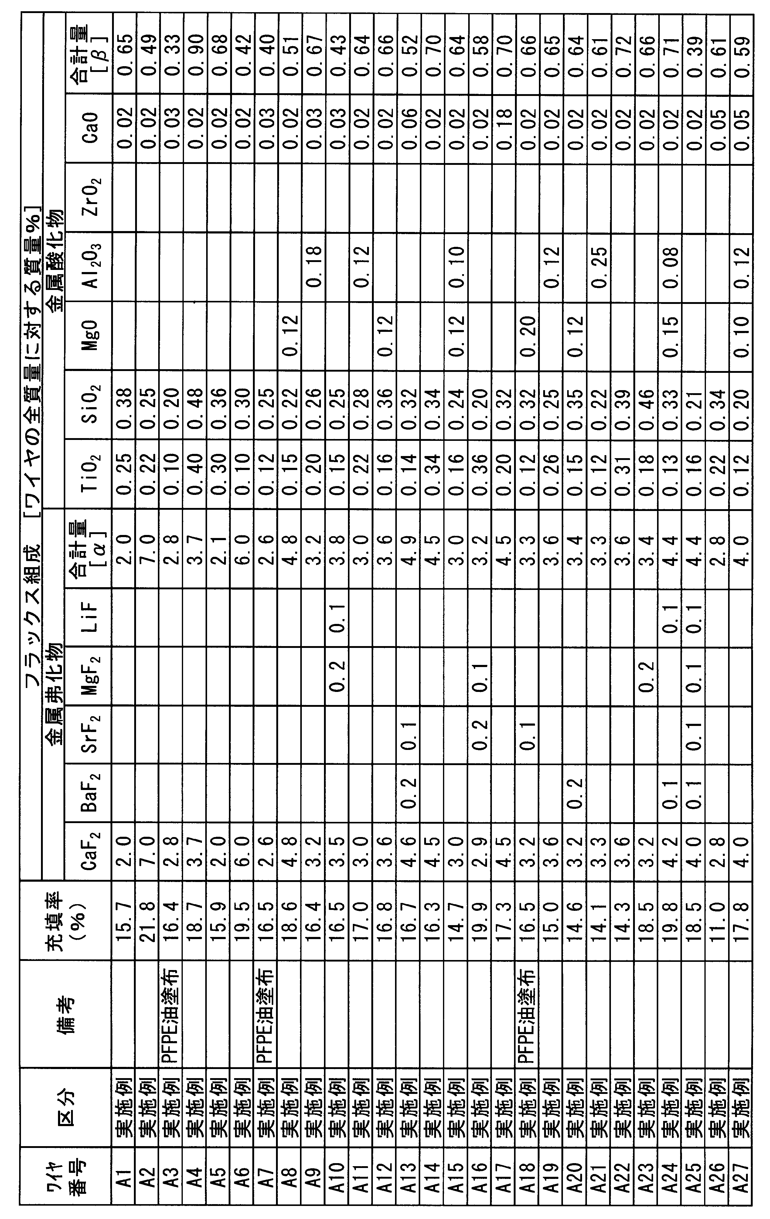
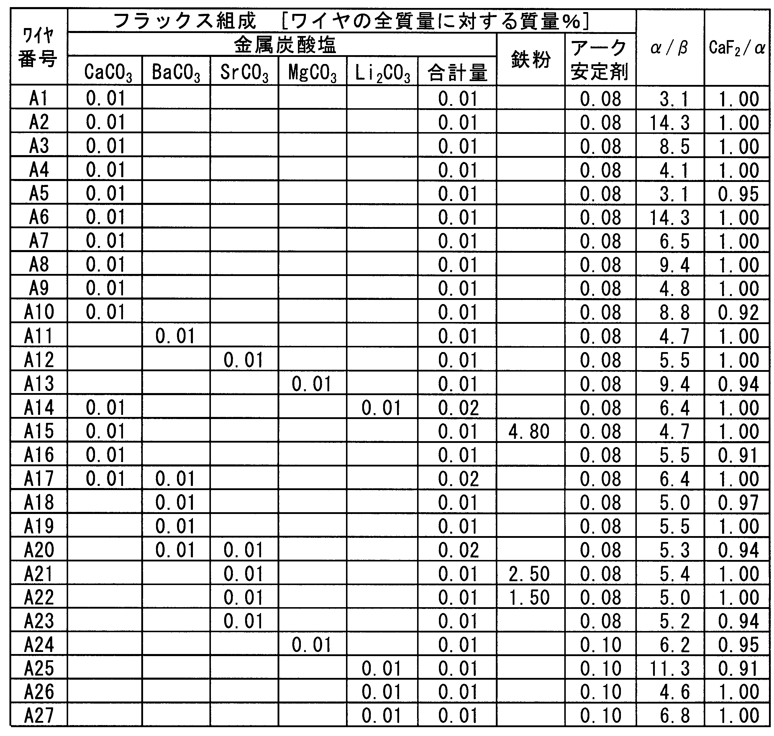
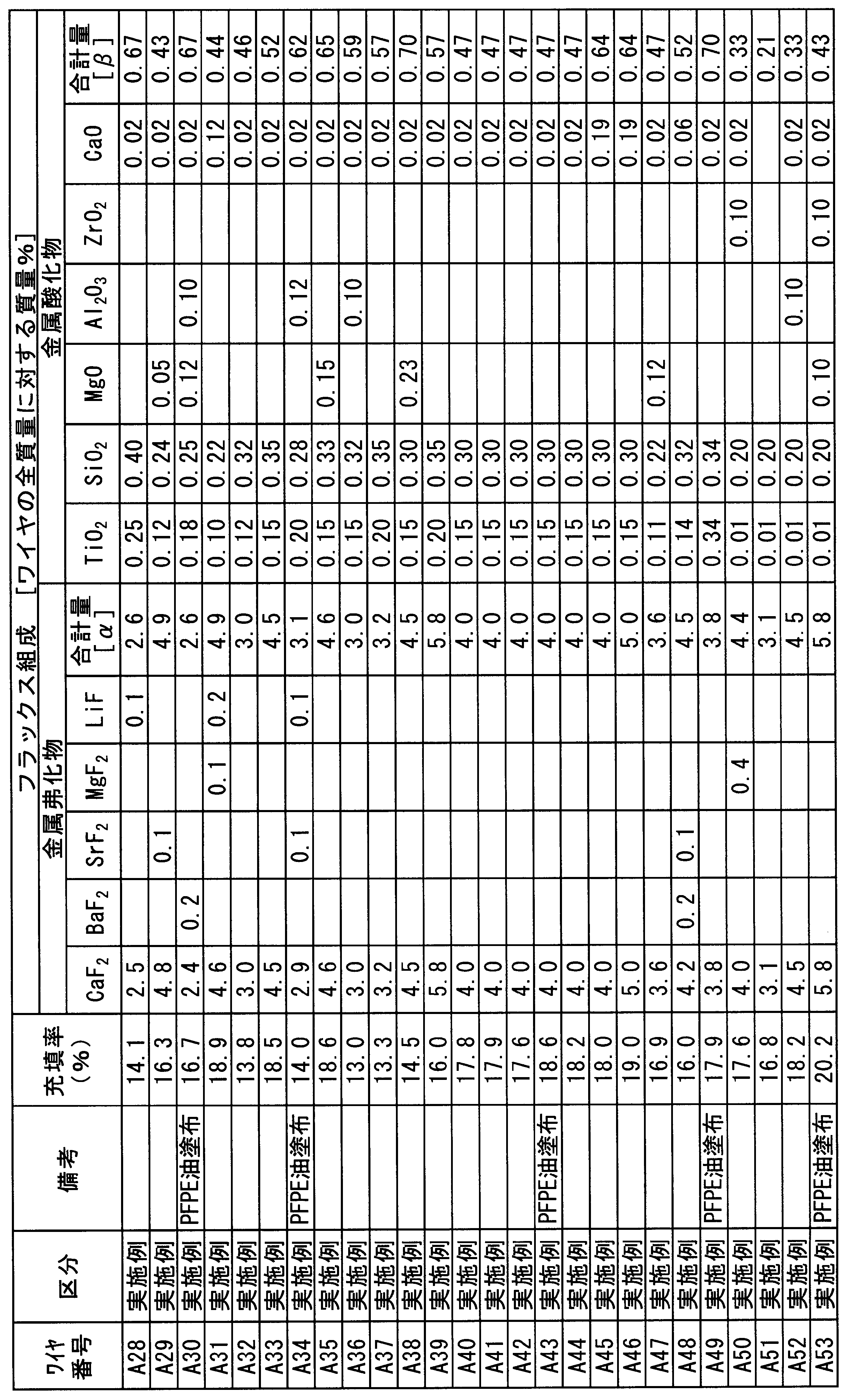


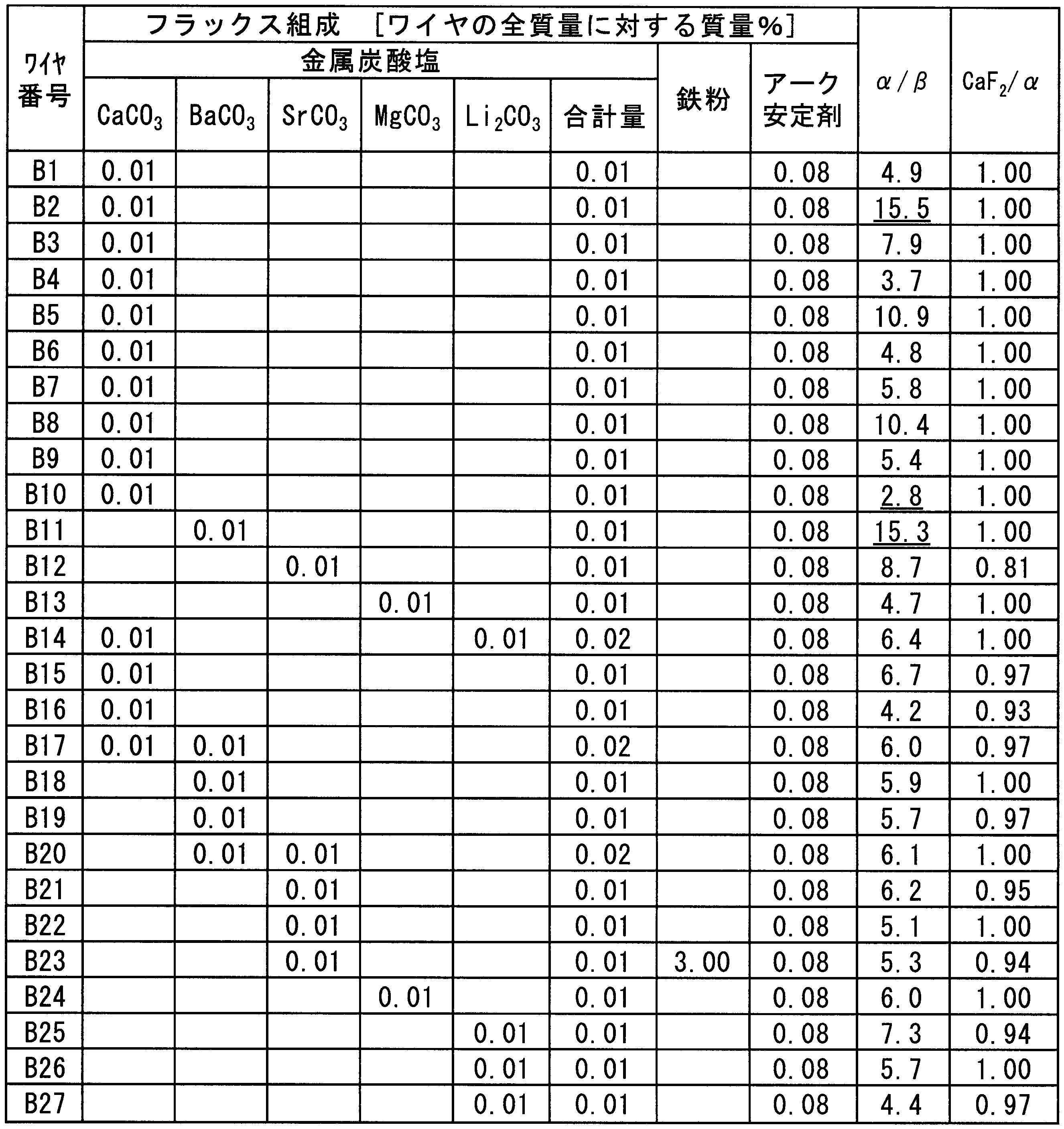
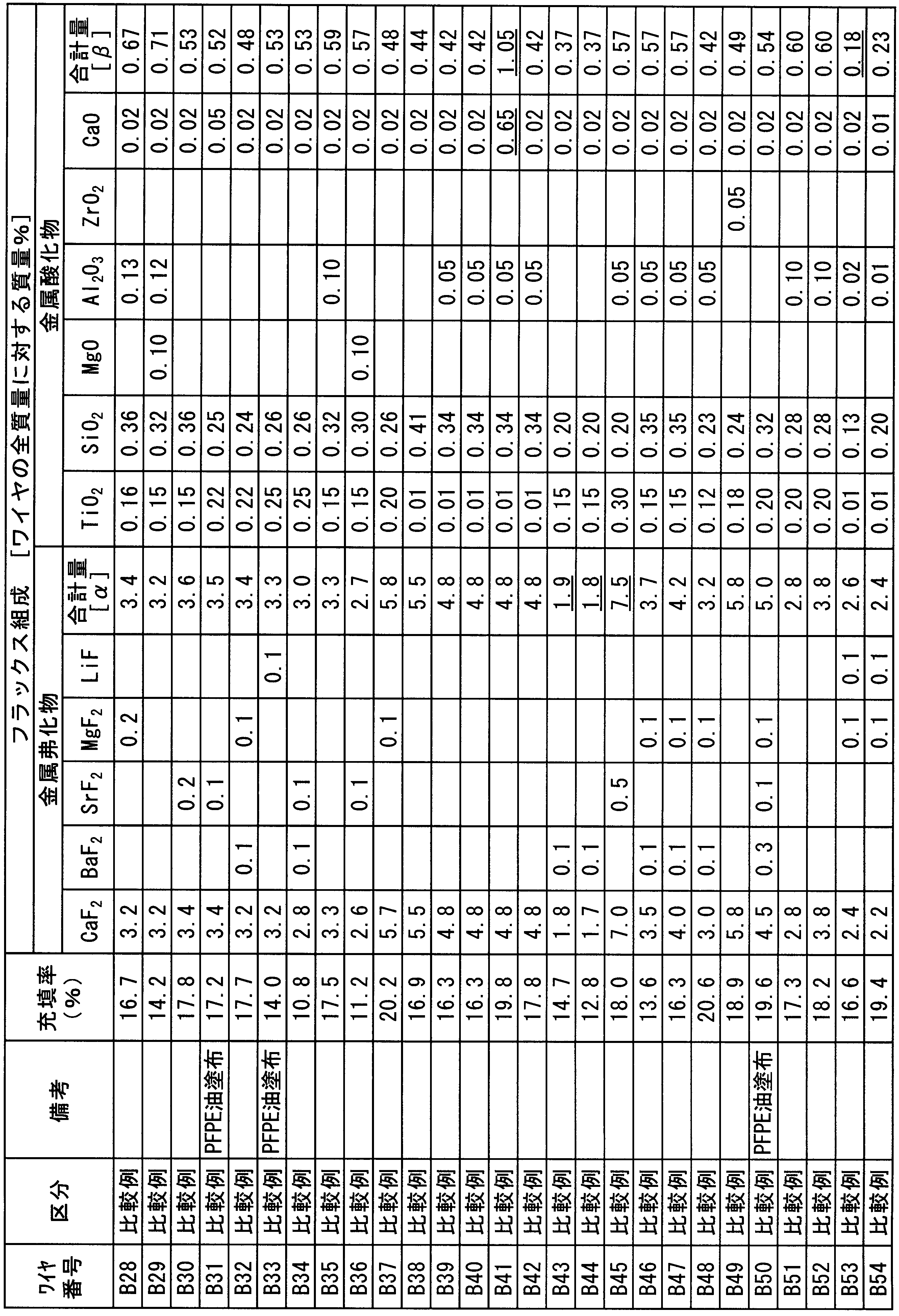
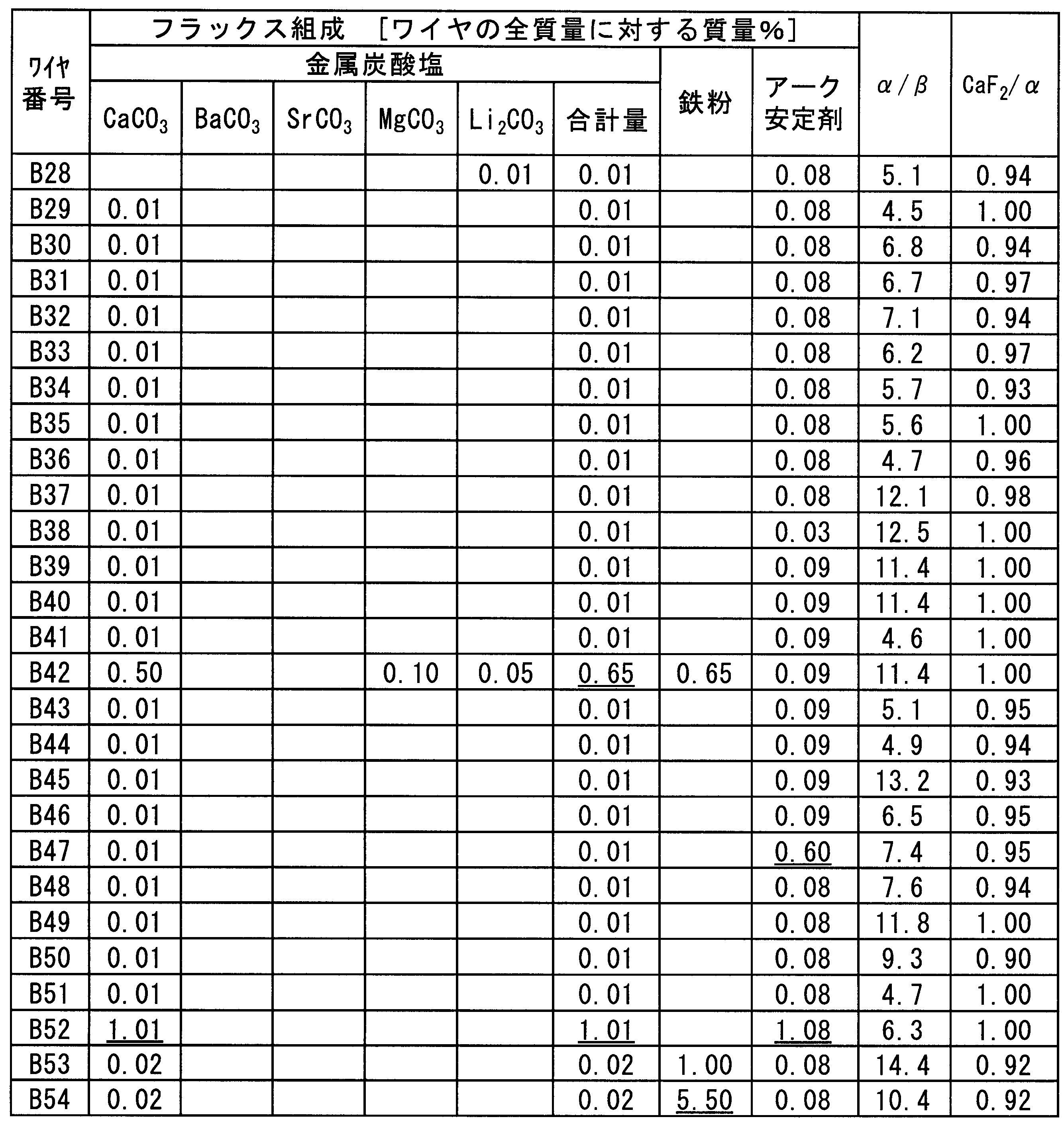
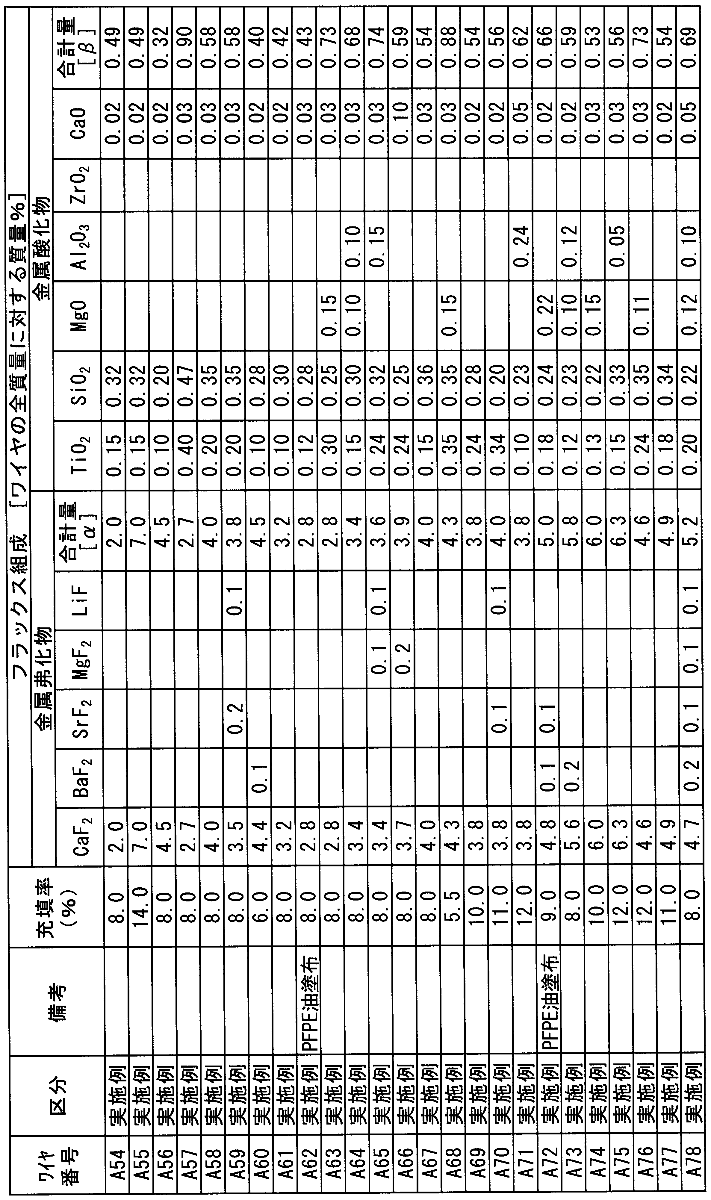

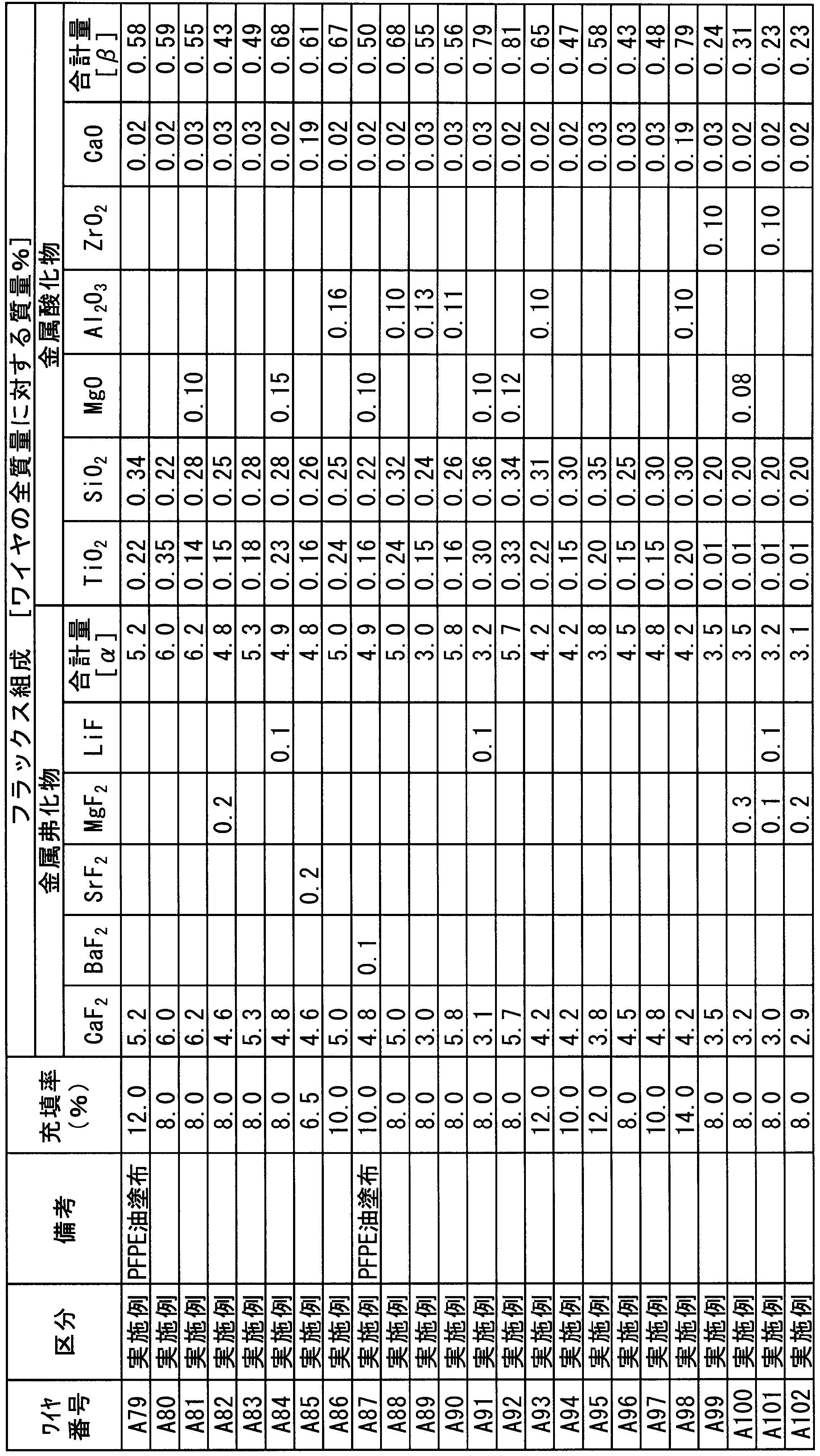
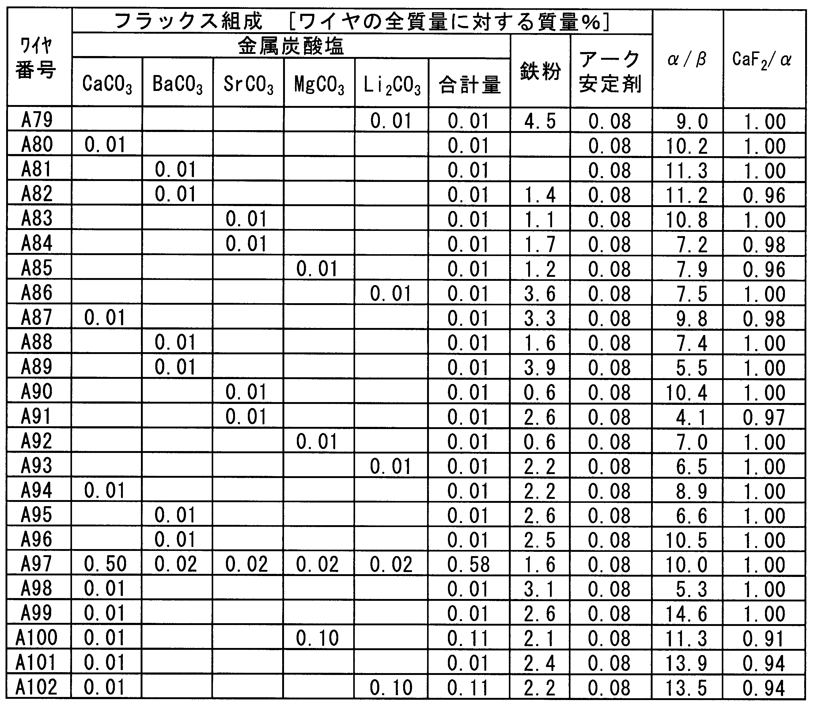

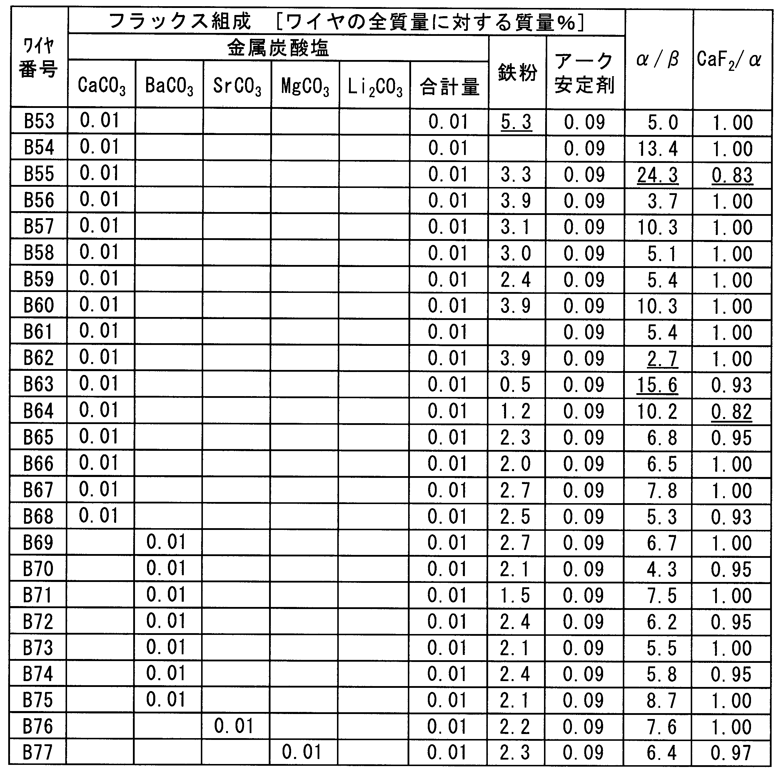
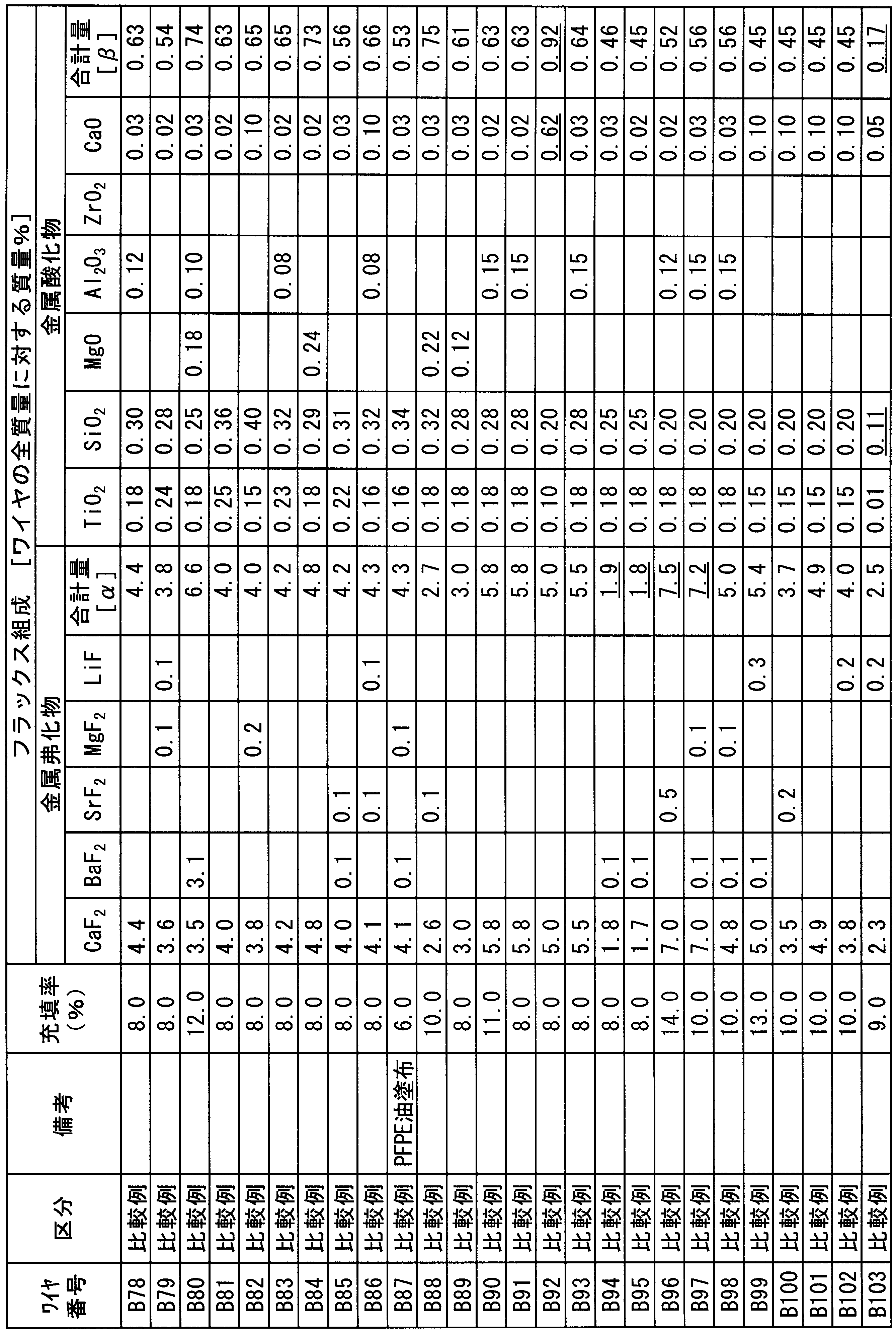
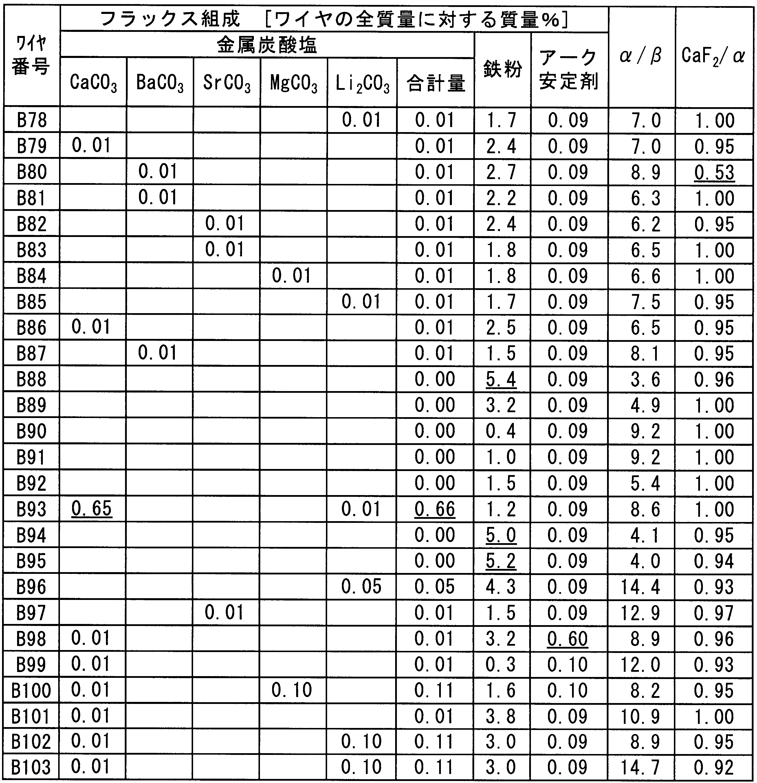

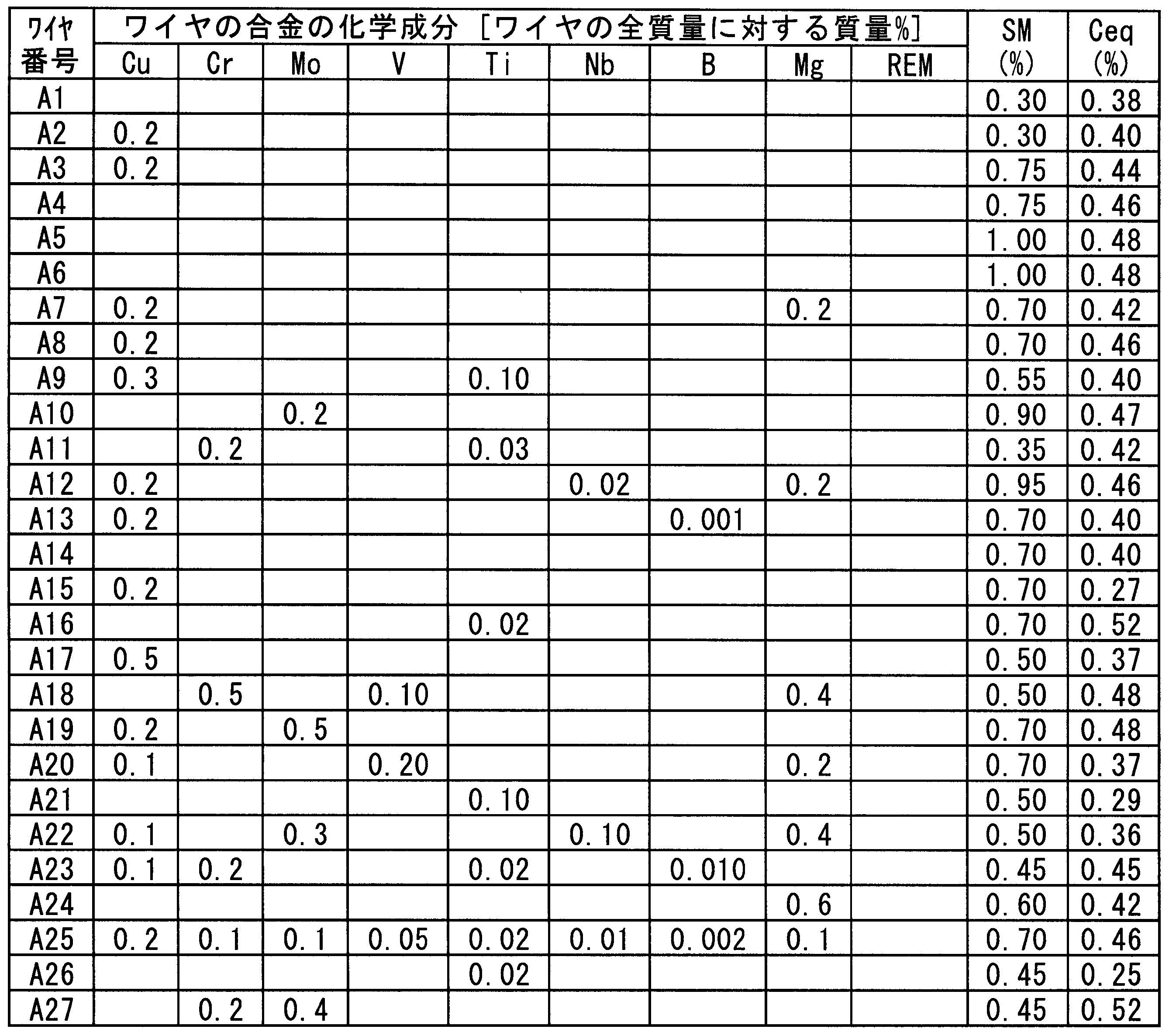

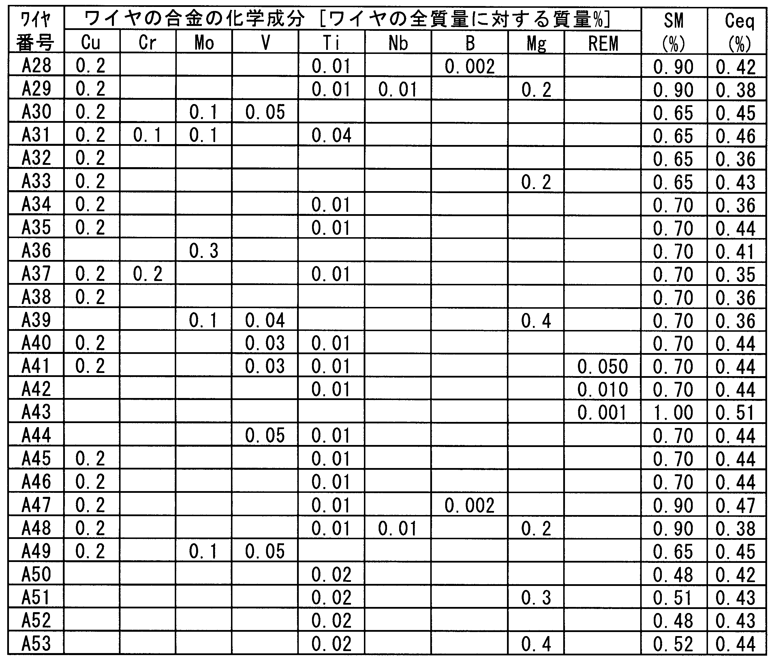


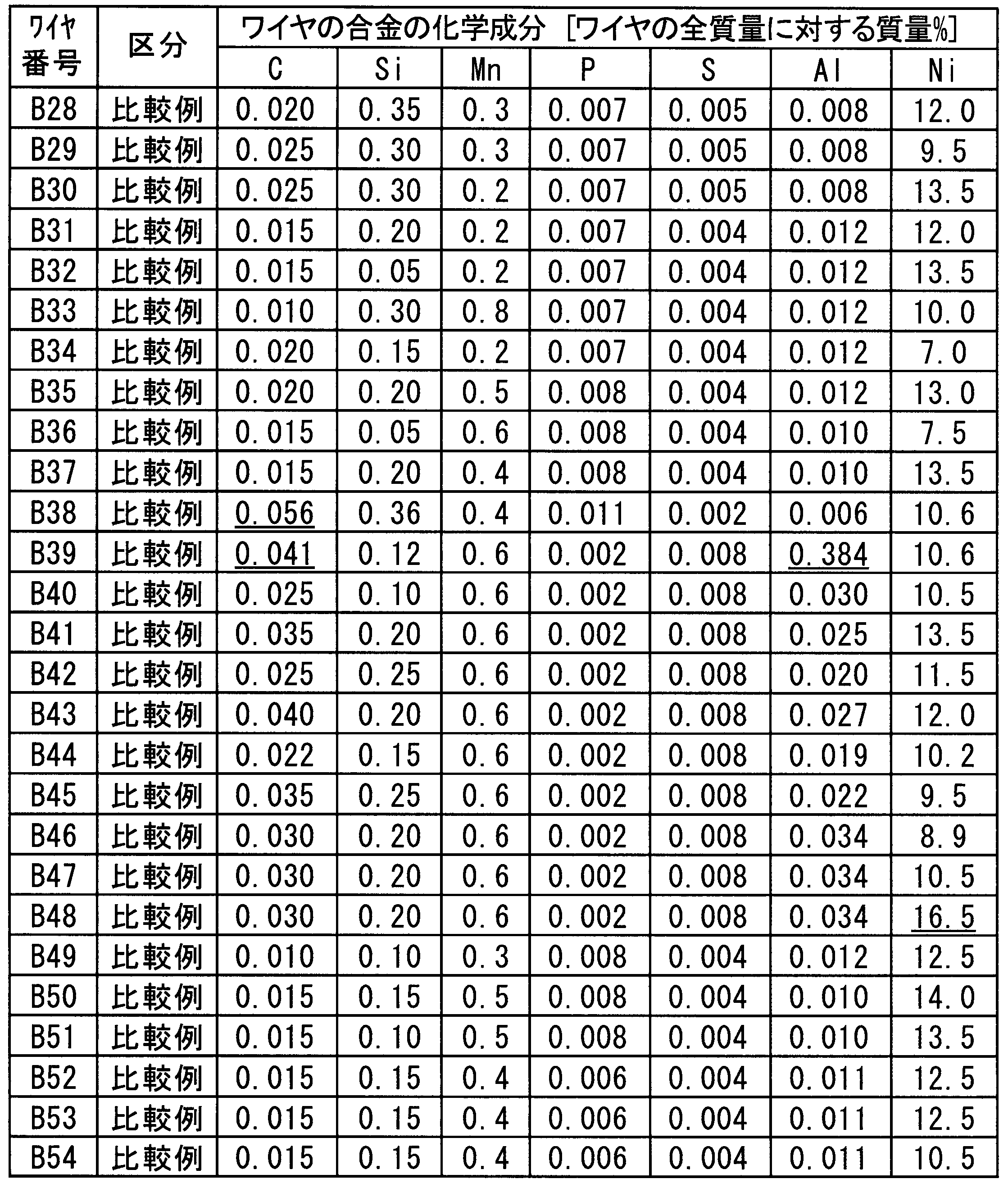

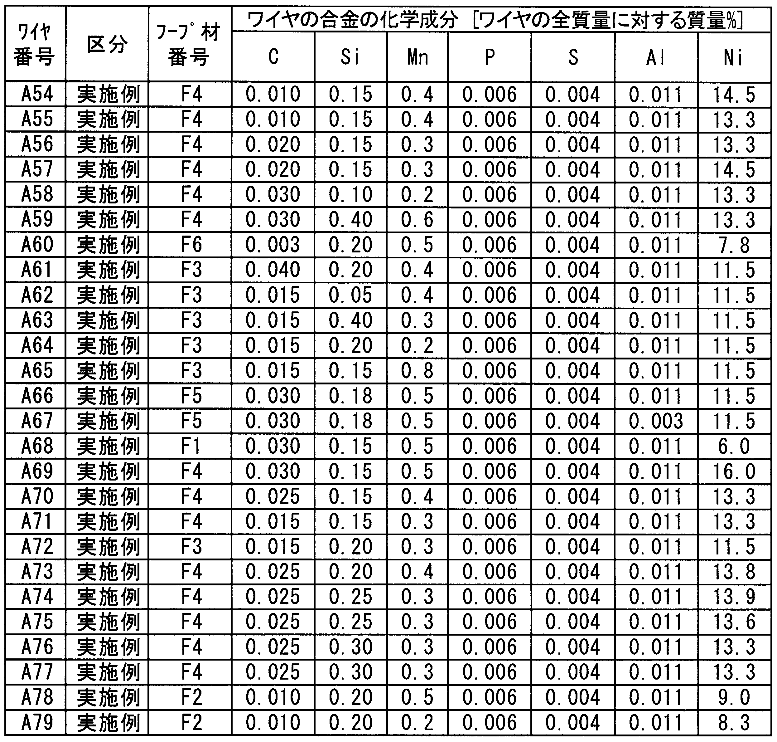
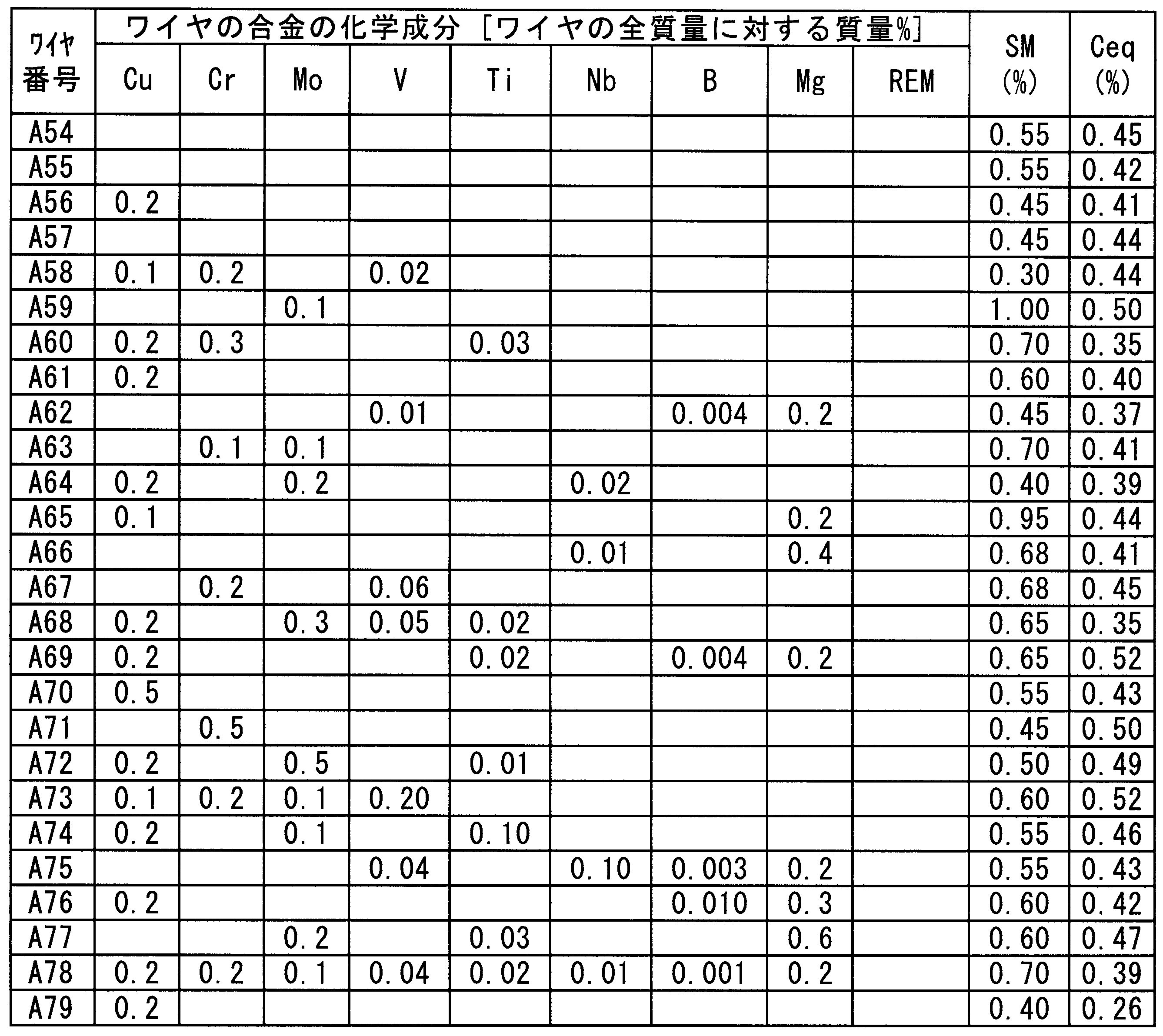


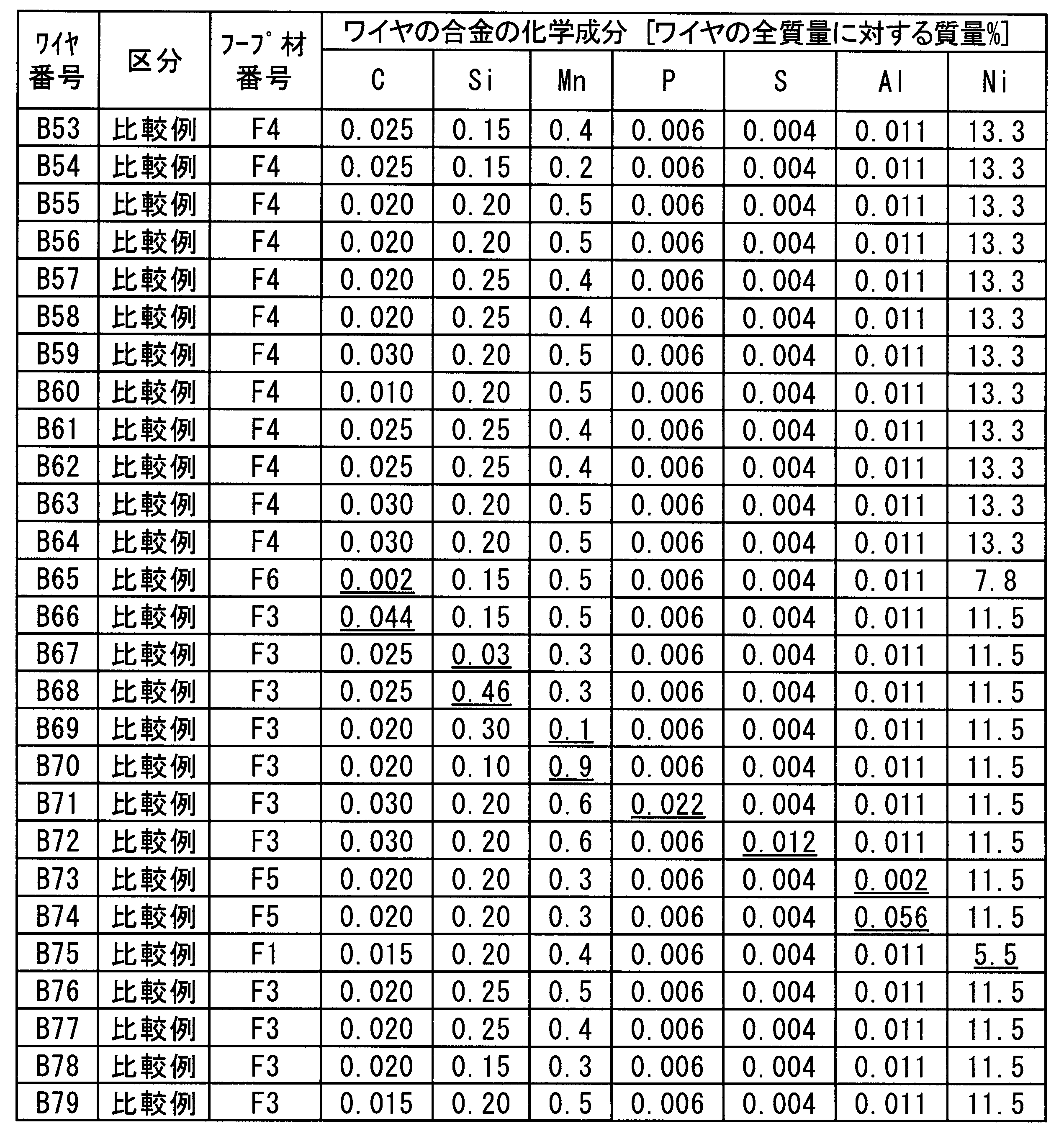
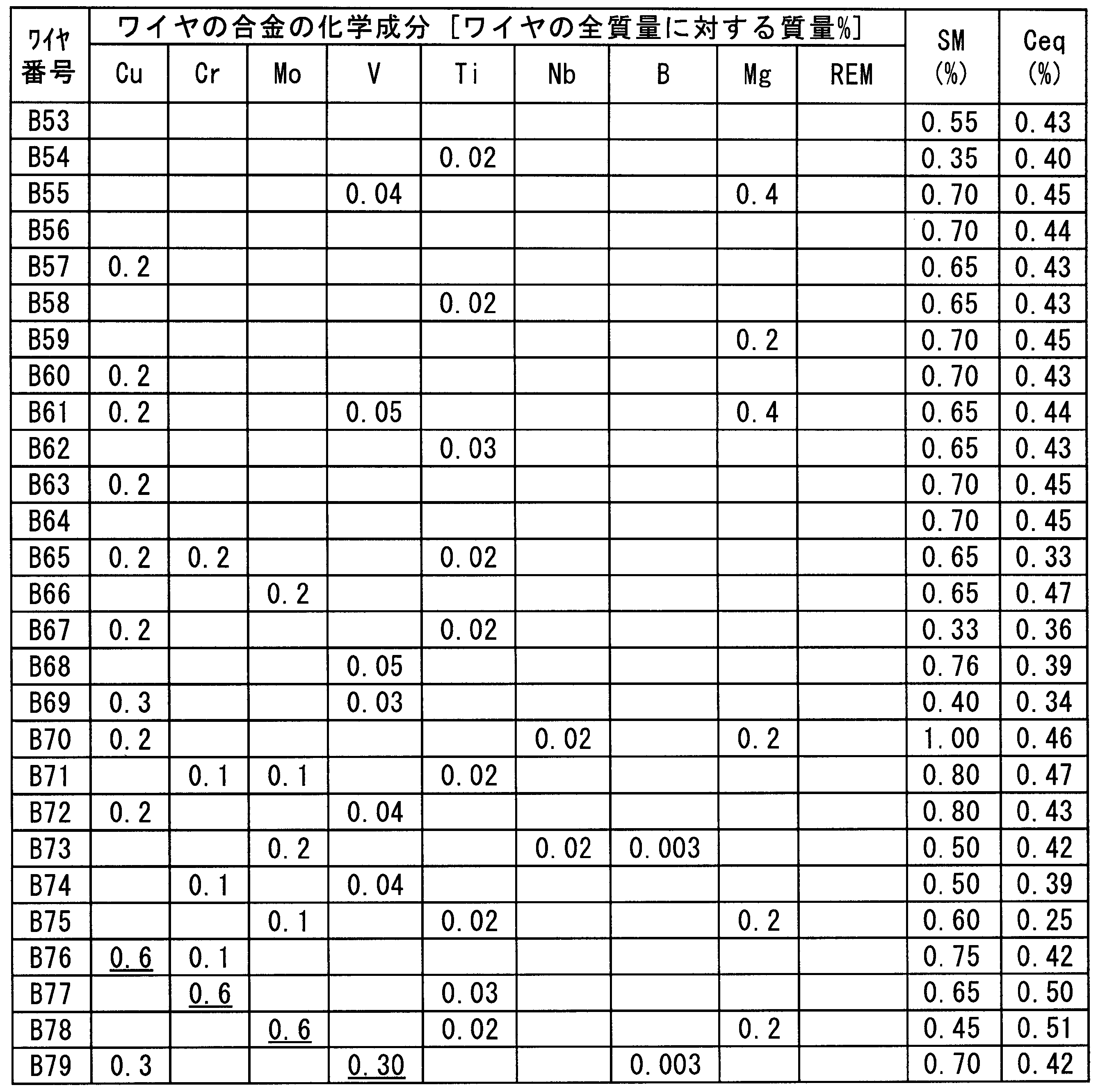
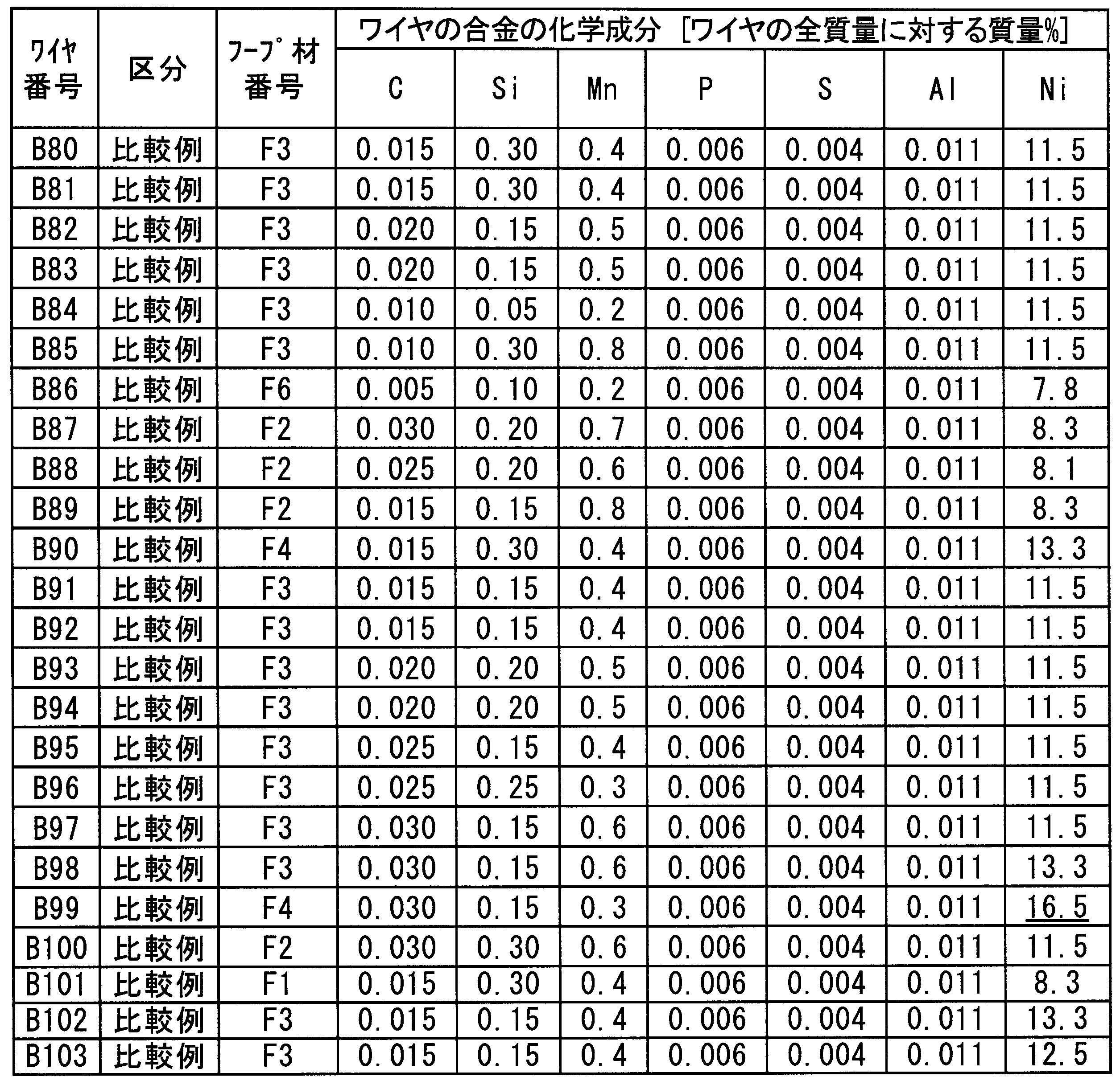
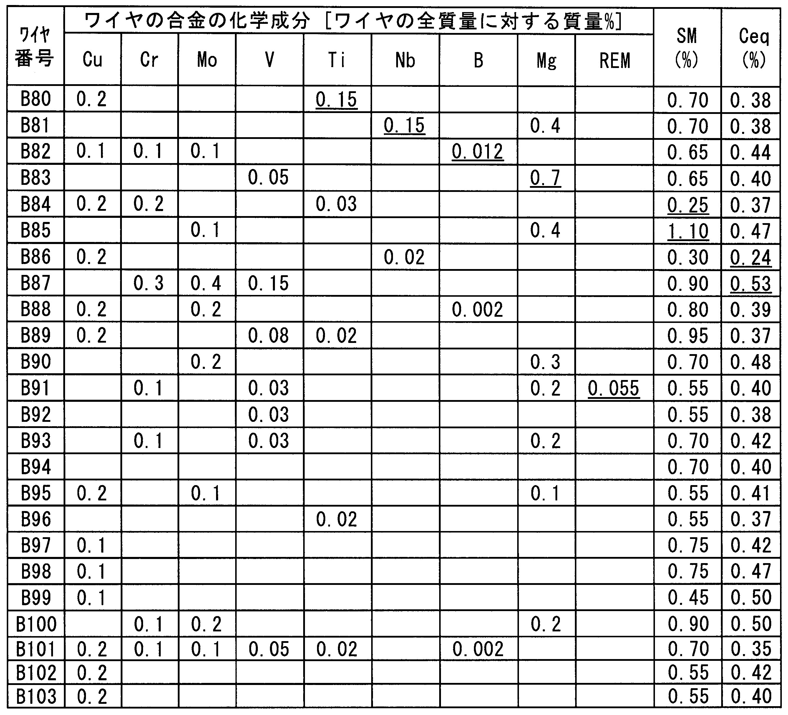
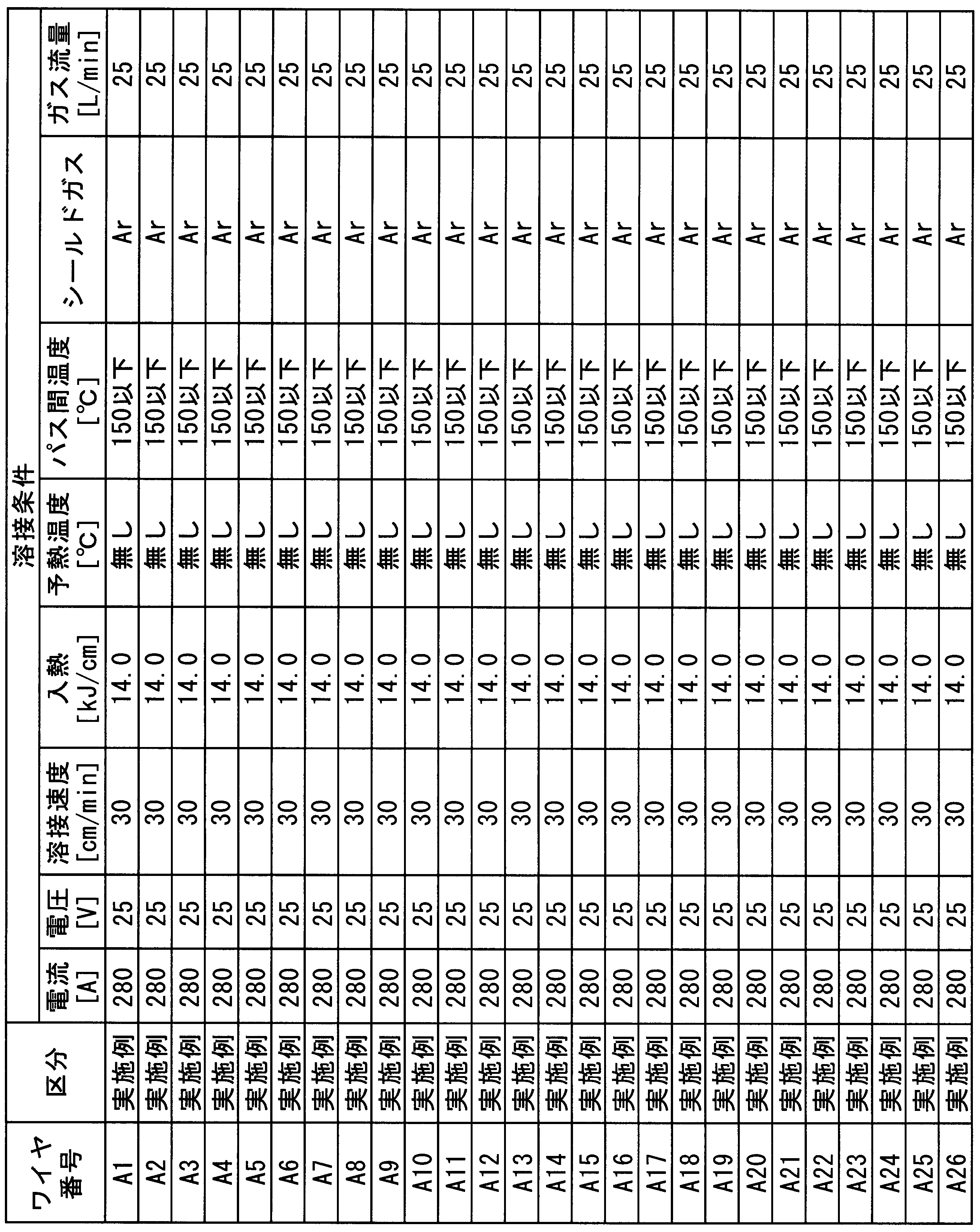

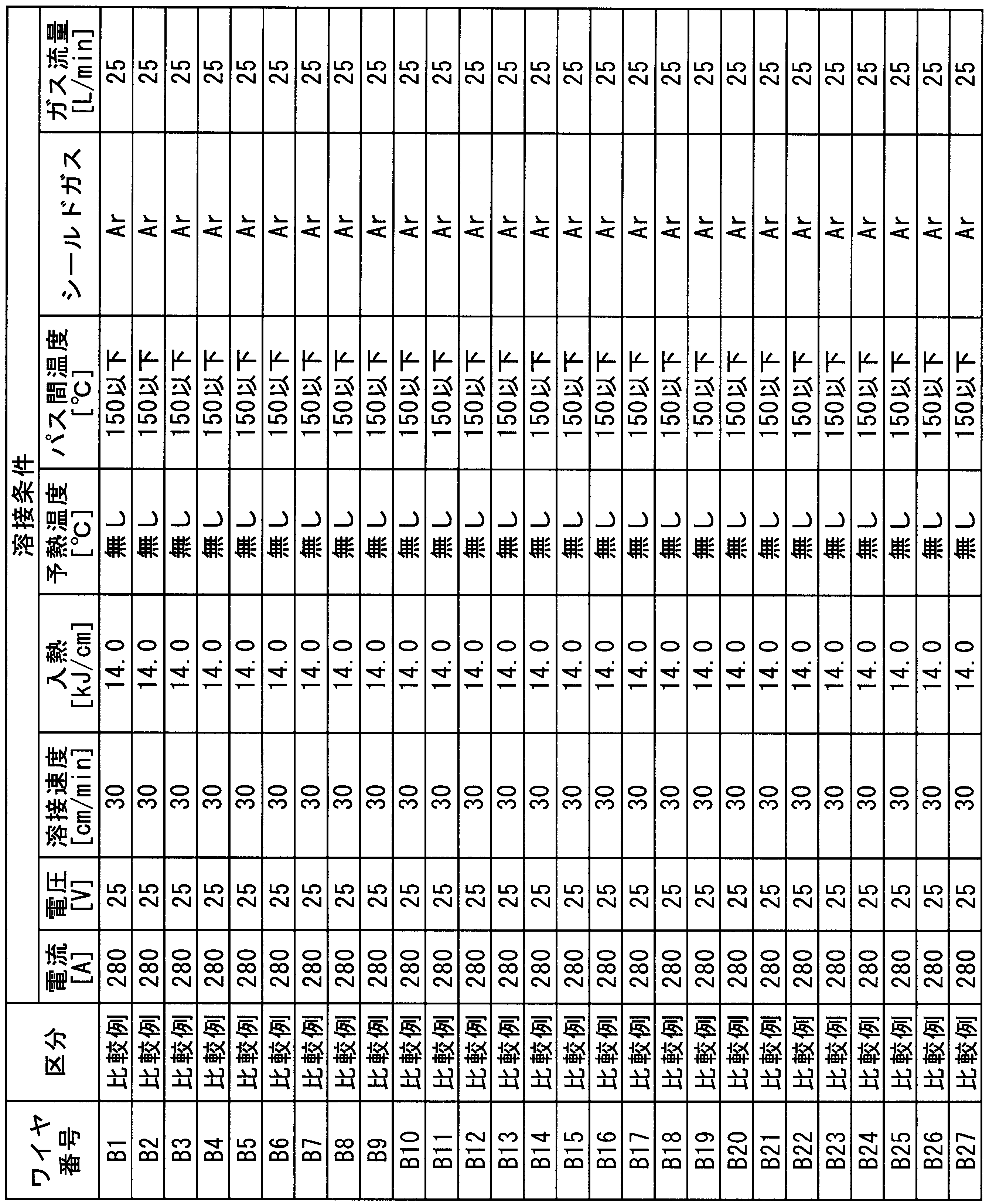
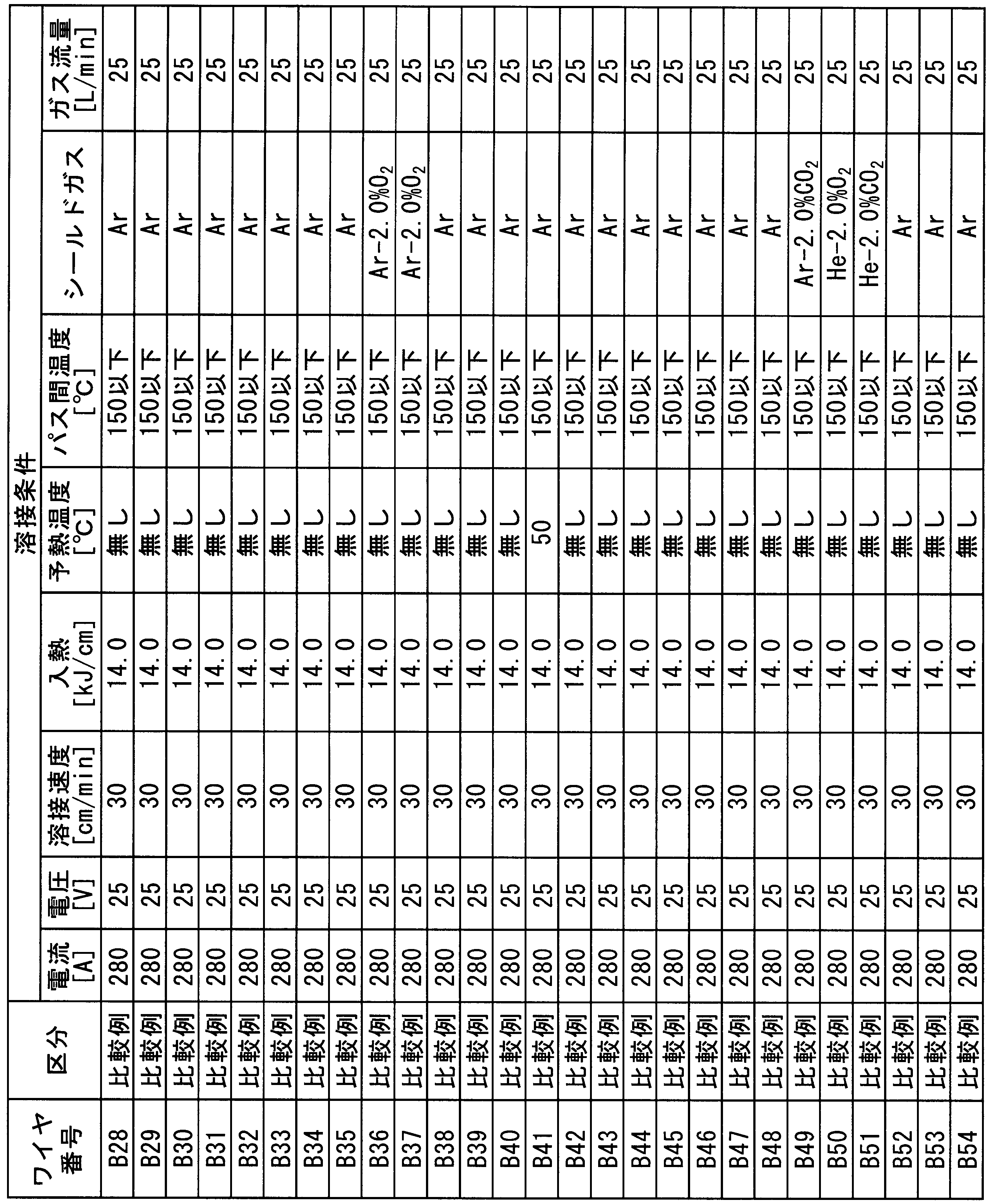


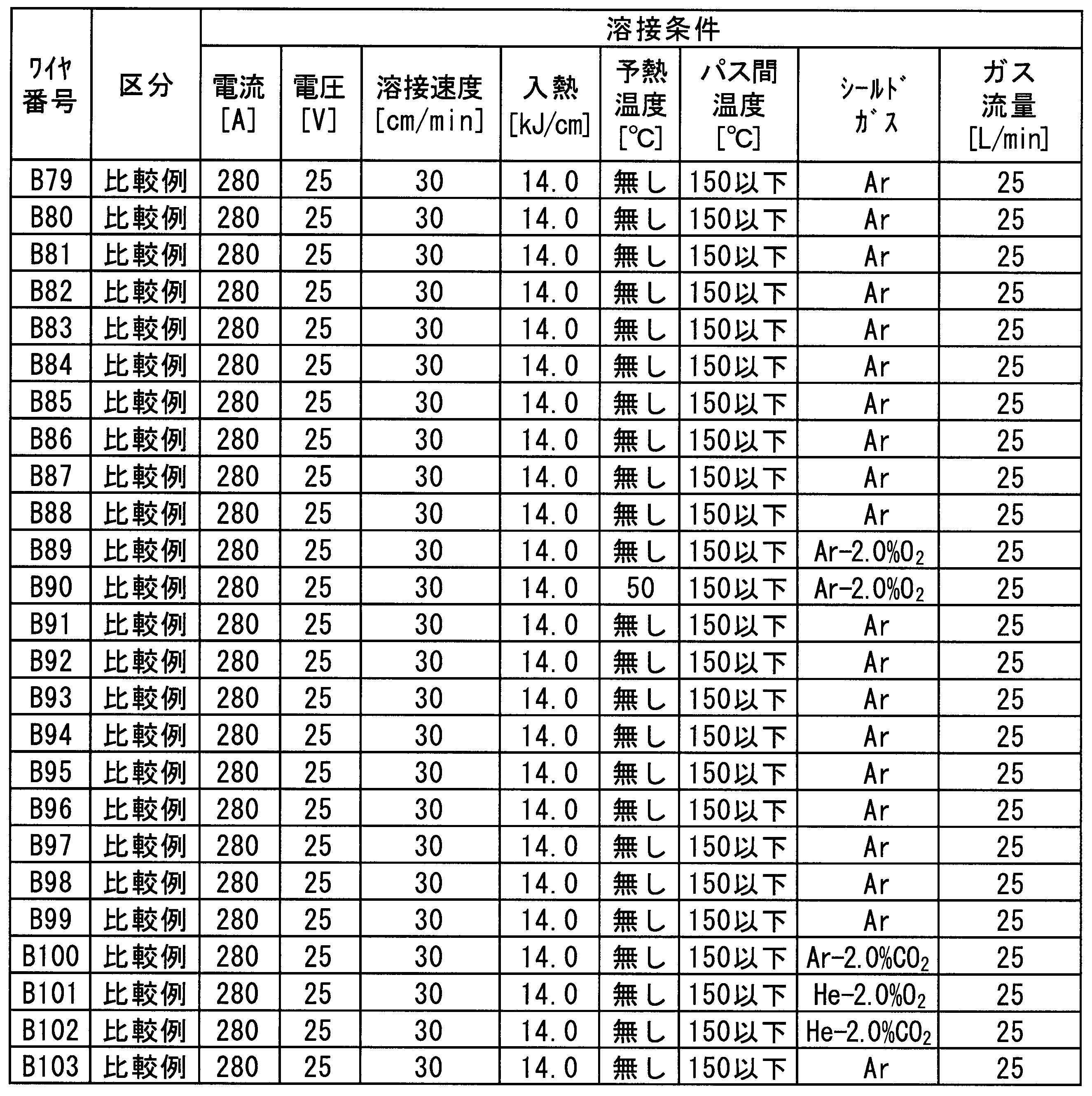
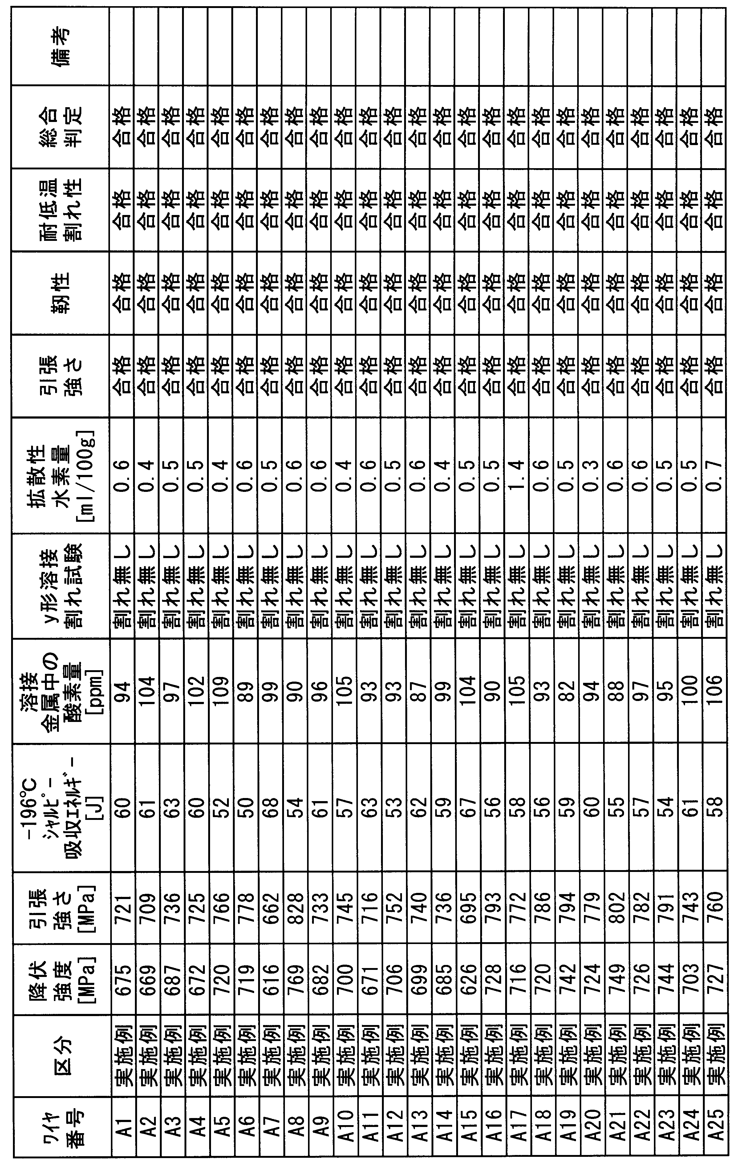
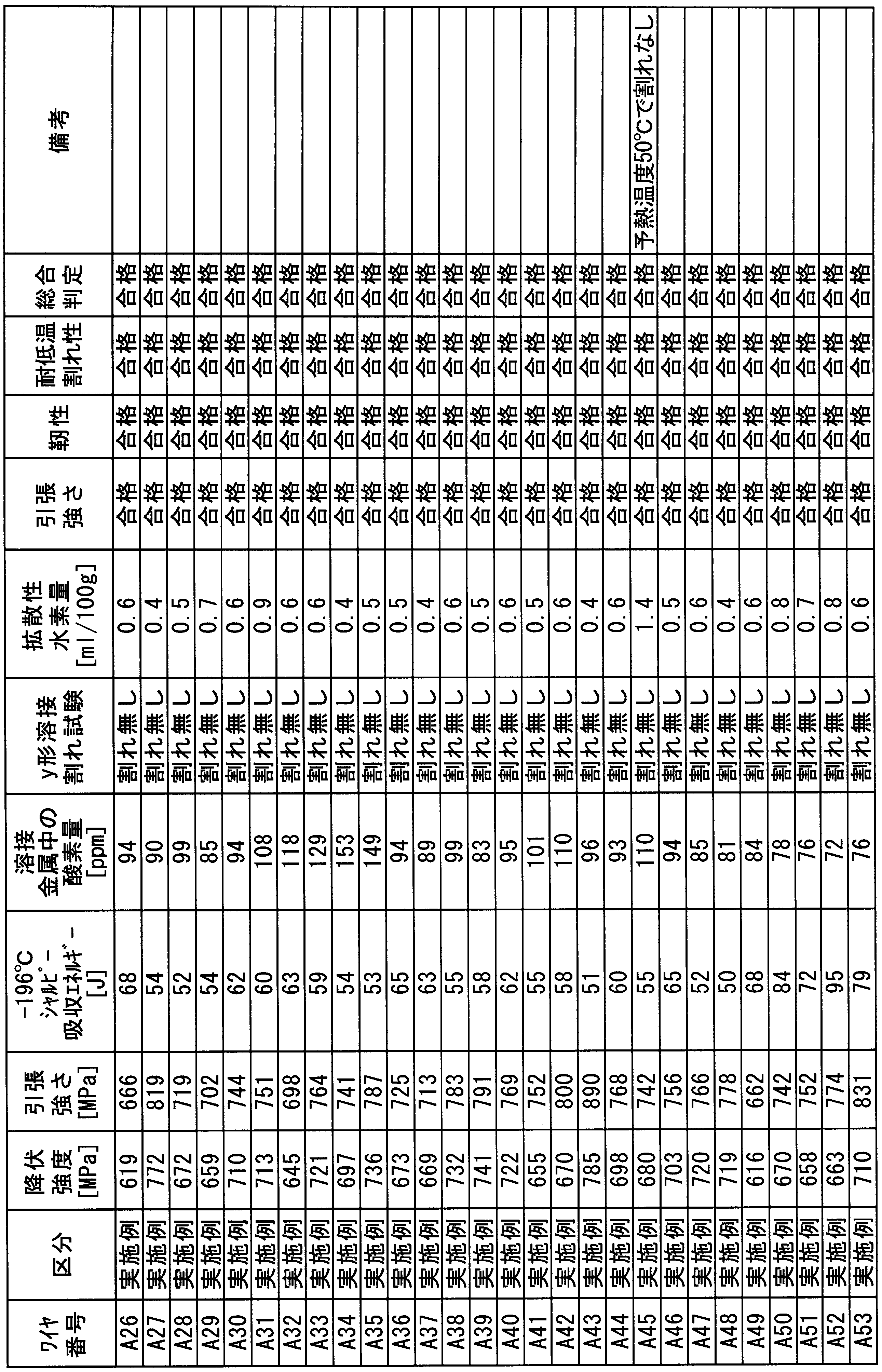
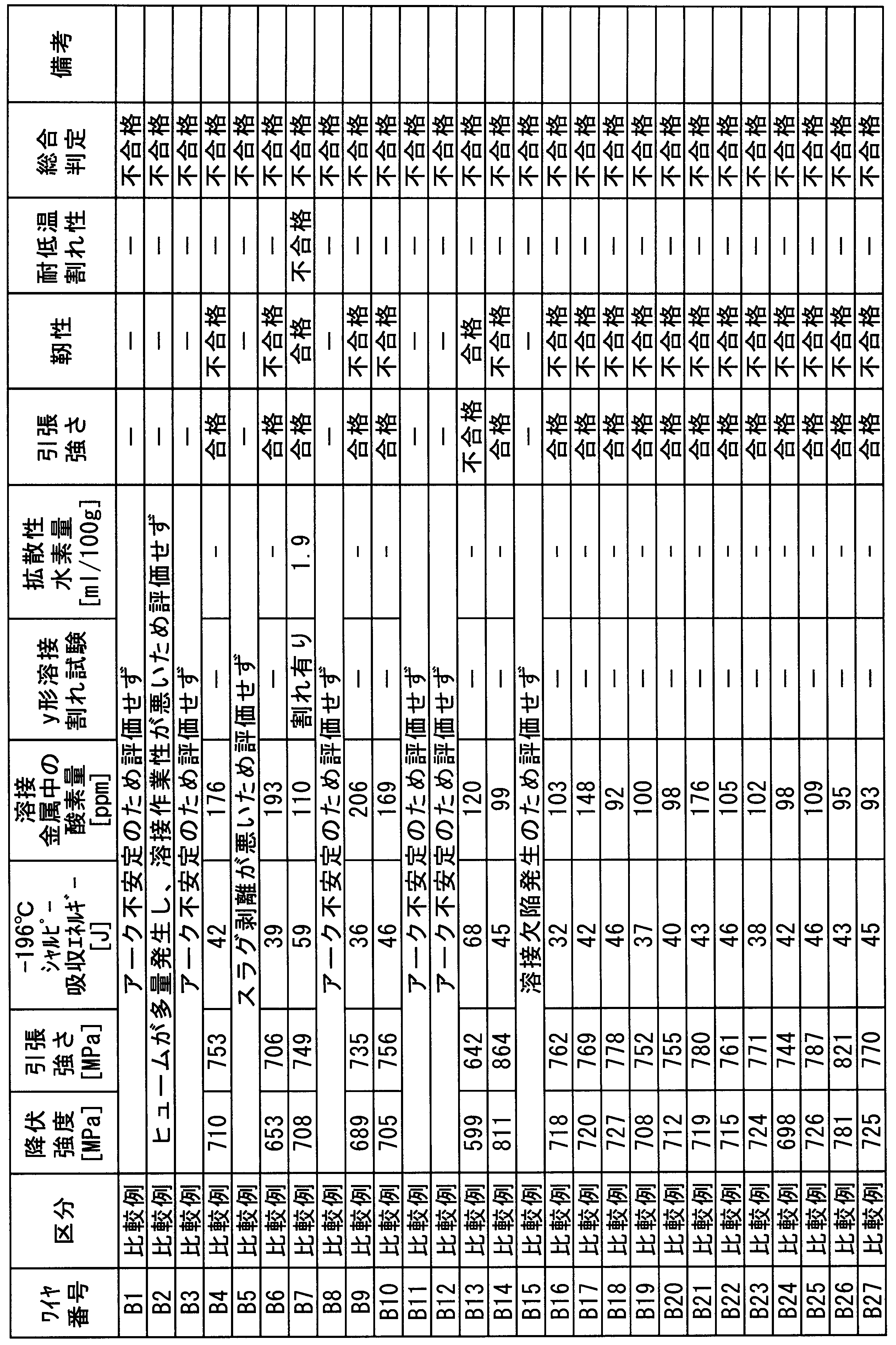
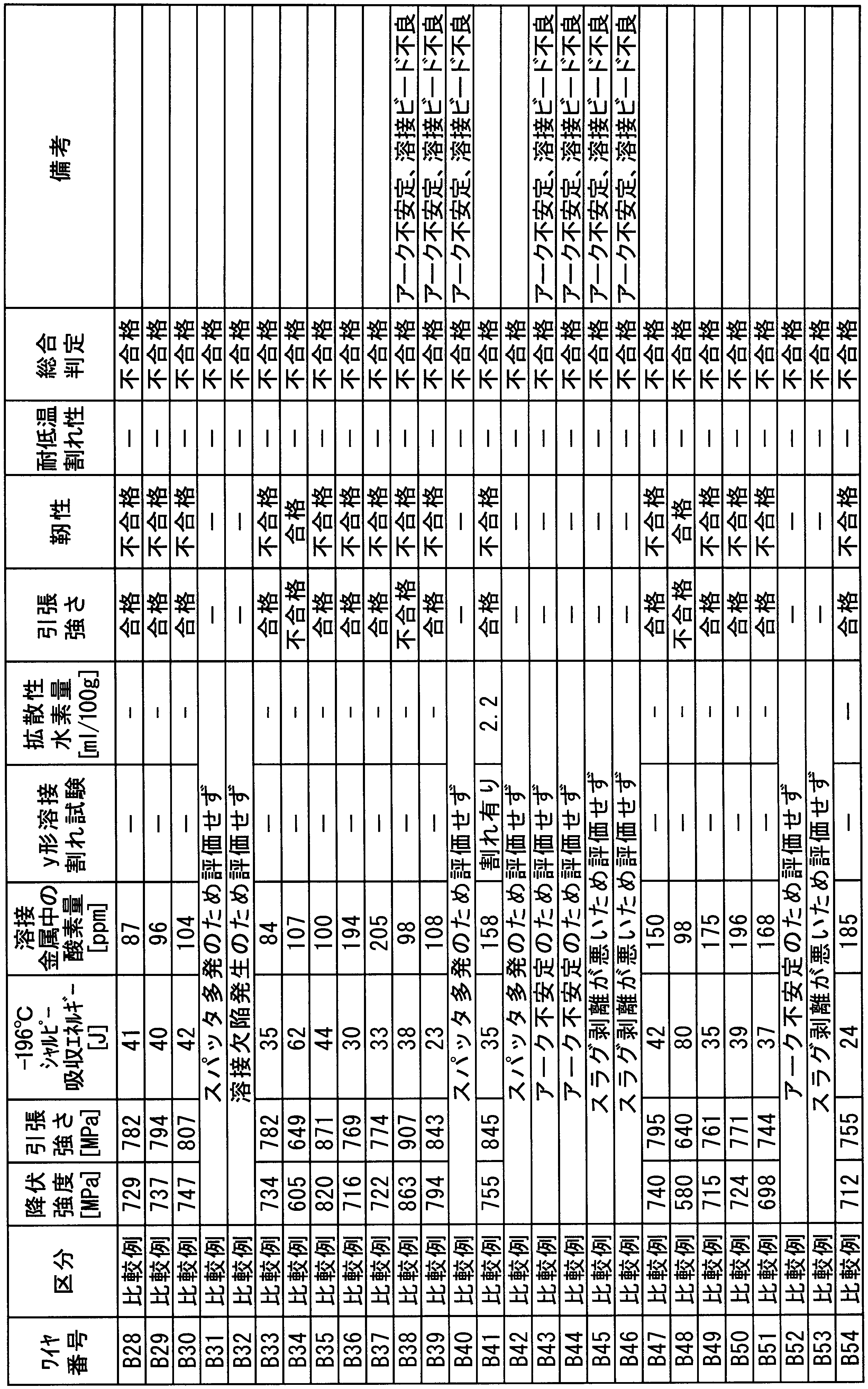
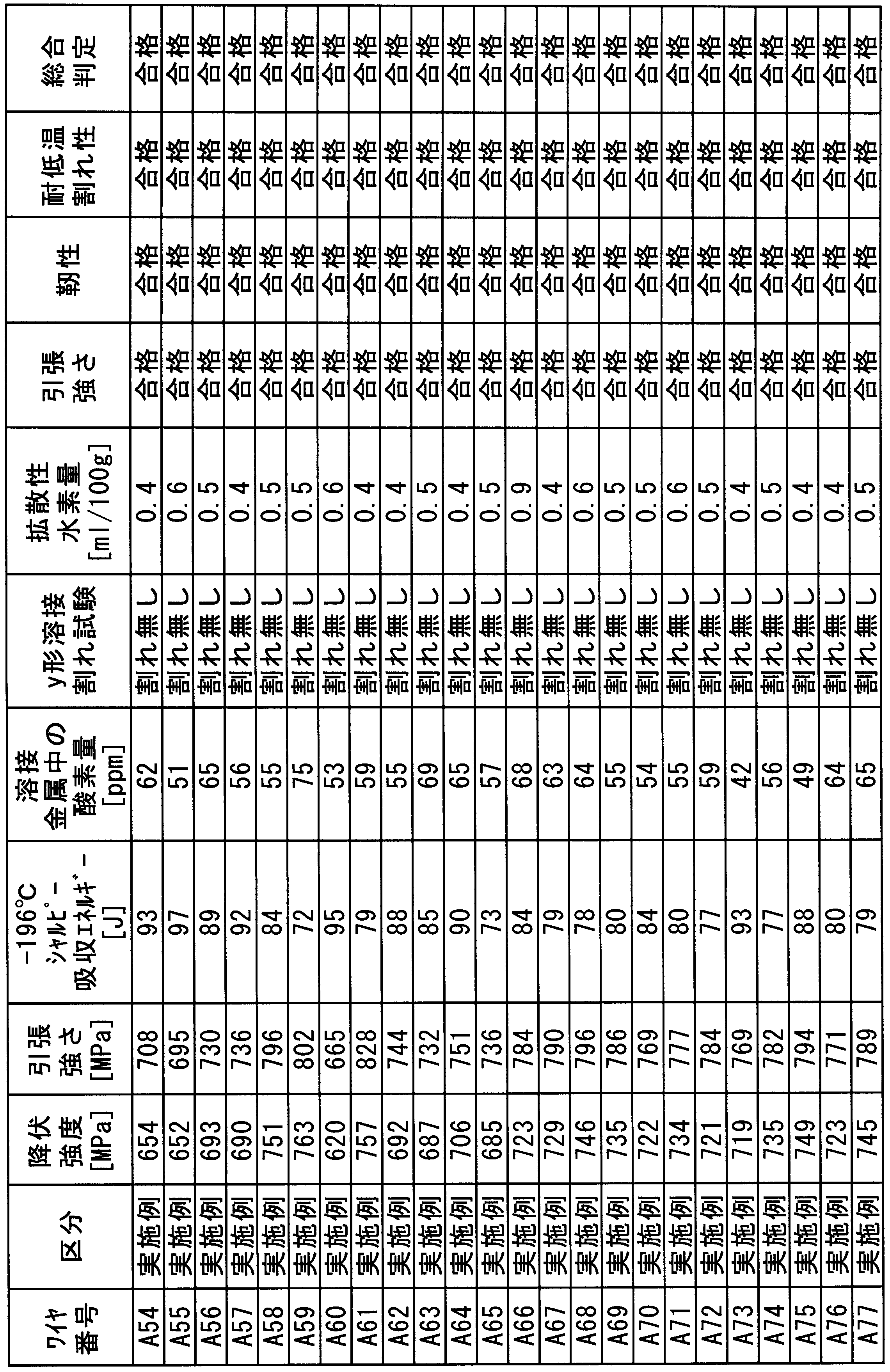
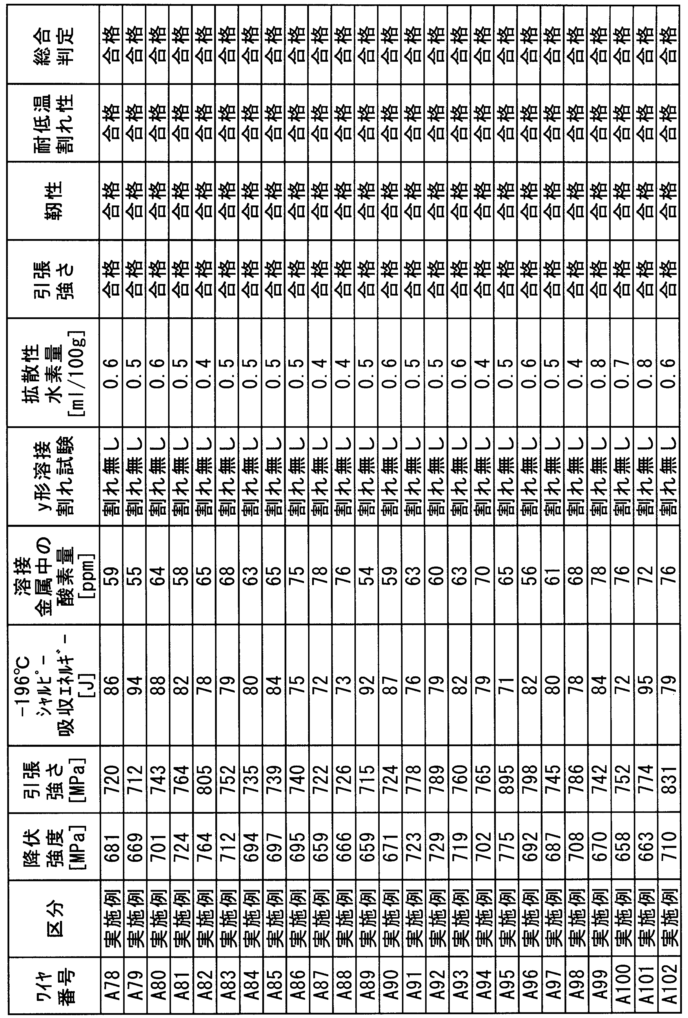

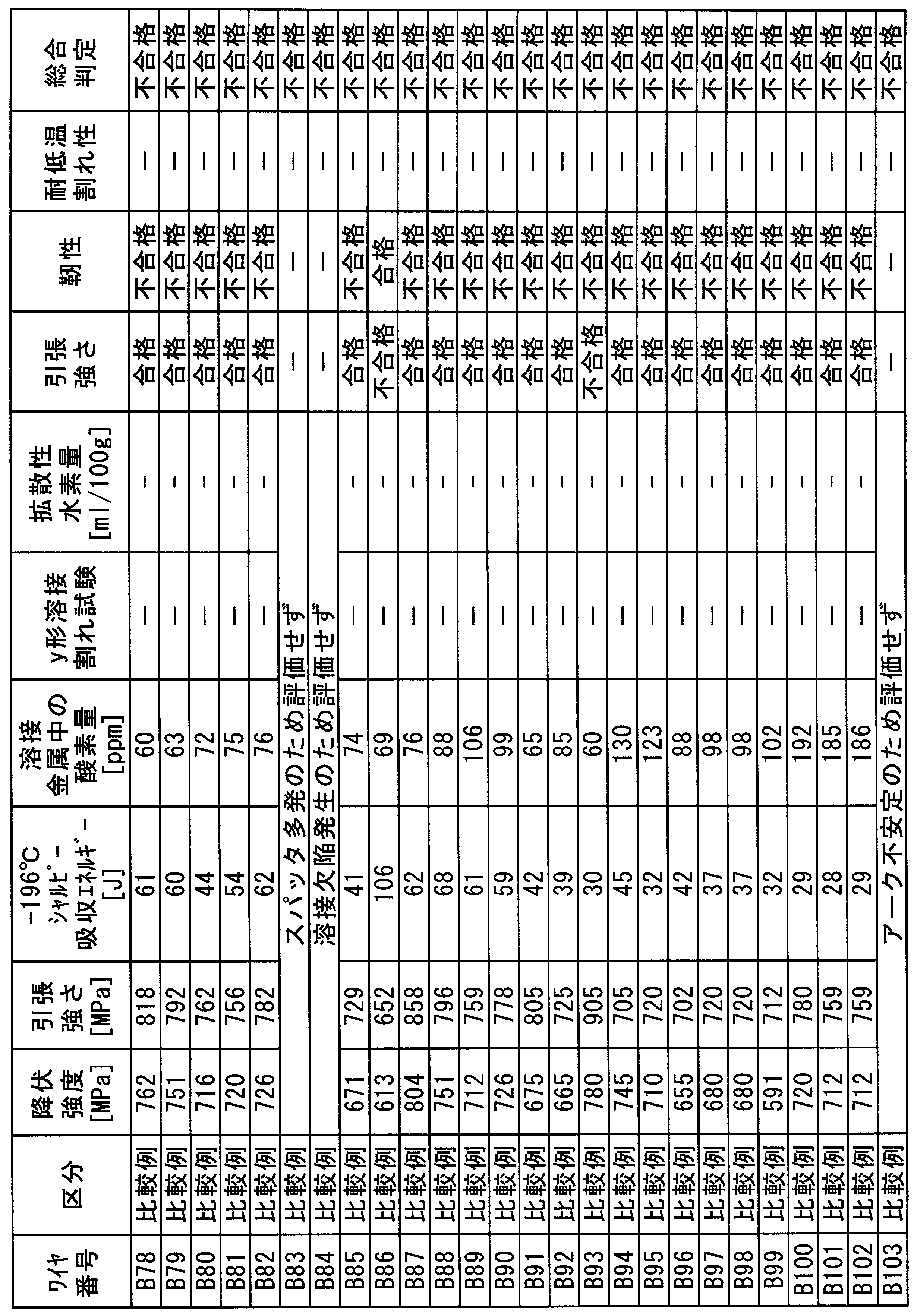

Niを5.5~9.5%程度含有するNi系低温用鋼の溶接に用いられるフラックス入りワイヤにおいて、Ni系低温用鋼並みにNi量を低減することで溶接材料コストを大幅に低減し、かつ、溶接施工効率に優れるガスシールドアーク溶接を適用でき、さらにワイヤ内に充填するフラックスの合金成分を低減し、溶接金属の酸素量を低減することで、-196℃の低温靭性の優れる溶接金属が得られる。さらに、低温割れを抑制するための予熱作業が不要、または、予熱作業を著しく低減できるフラックス入りワイヤを提供することができ、産業界における価値はきわめて高い。
1 鋼板
2 裏当金
3 溶接ビード
4 シャルピー衝撃試験片(2mmVノッチ)
5 A0号引張り試験片(丸棒)
2 裏当金
3 溶接ビード
4 シャルピー衝撃試験片(2mmVノッチ)
5 A0号引張り試験片(丸棒)
Claims (9)
- 鋼製外皮の内部にフラックスが充填されたフラックス入りワイヤであって、前記フラックス入りワイヤ中に、
金属弗化物であるCaF2、BaF2、SrF2、MgF2、及びLiFのうちの1種または2種以上が含有され、その含有量の合計をαとしたとき、前記αが前記フラックス入りワイヤの全質量に対する質量%で2.0~7.0%であり、
金属酸化物であるTi酸化物、Si酸化物、Mg酸化物、Al酸化物、Zr酸化物、及びCa酸化物のうちの1種または2種以上が含有され、その含有量の合計をβとしたとき、前記βが前記フラックス入りワイヤの全質量に対する質量%で0.2~0.9%であり、
金属炭酸塩であるCaCO3、BaCO3、SrCO3、MgCO3、及びLi2CO3のうちの1種または2種以上が含有され、その含有量の合計が、前記フラックス入りワイヤの全質量に対する質量%で0.6%未満であり、
前記αに対する前記CaF2の含有量の比が0.90以上であり、
前記βに対する前記αの比が3.0以上15.0以下であり、
前記Ti酸化物の含有量が、前記フラックス入りワイヤの全質量に対する質量%で0~0.4%であり、
前記Si酸化物の含有量が、前記フラックス入りワイヤの全質量に対する質量%で0.2~0.5%であり、
前記Ca酸化物の含有量が、前記フラックス入りワイヤの全質量に対する質量%で0.20%未満であり、
前記CaCO3の含有量が、前記フラックス入りワイヤの全質量に対する質量%で0.6%未満であり、
前記フラックス中のアーク安定剤の含有量が、前記フラックス入りワイヤの全質量に対する質量%で0~0.5%であり、
前記フラックス中の鉄粉の含有量が、前記フラックス入りワイヤの全質量に対する質量%で5%未満であり、
前記金属弗化物、前記金属酸化物、及び前記金属炭酸塩を除く化学成分が、前記フラックス入りワイヤの全質量に対する質量%で:
C:0.003~0.040%;
Si:0.05~0.40%;
Mn:0.2~0.8%;
Al:0.003~0.050%;
Ni:6.0~16.0%;
P:0.02%以下;
S:0.01%以下;
Cu:0~0.5%;
Cr:0~0.5%;
Mo:0~0.5%;
V:0~0.2%;
Ti:0~0.1%;
Nb:0~0.1%;
B:0~0.01%;
Mg:0~0.6%;
REM:0~0.0500%;
残部:Feおよび不純物;
からなり、
下記の式aで定義されるSMが0.3~1.0%であり、
下記の式bで定義されるCeqが0.25~0.52%である
ことを特徴とするフラックス入りワイヤ。
SM=[Si]+[Mn] ・・・(式a)
Ceq=[C]+1/24[Si]+1/6[Mn]+1/40[Ni]+1/5[Cr]+1/4[Mo]+1/14[V] ・・・(式b)
但し、式a及び式bの[]付元素は、それぞれの元素の含有量(質量%)を表す。 - Niを含有する前記鋼製外皮の内部に前記フラックスが充填された前記フラックス入りワイヤであって、前記鋼製外皮の前記Niの含有量が、前記鋼製外皮の全質量に対する質量%で6~18%であることを特徴とする請求項1に記載のフラックス入りワイヤ。
- 前記フラックス入りワイヤ中の前記REMの含有量が、前記フラックス入りワイヤの全質量に対する質量%で0.0100%以下であることを特徴とする請求項1または2に記載のフラックス入りワイヤ。
- 前記フラックス入りワイヤ中の前記CaOの含有量が、前記フラックス入りワイヤの全質量に対する質量%で0.20%未満であることを特徴とする請求項1~3のいずれか1項に記載のフラックス入りワイヤ。
- 前記フラックス入りワイヤを用いたガスシールドアーク溶接における、日本工業規格JIS Z3111-2005に規定された溶接金属の引張試験において、前記溶接金属の引張強さが660~900MPaであることを特徴とする請求項1~4のいずれか1項に記載のフラックス入りワイヤ。
- 前記フラックス入りワイヤは、前記鋼製外皮にスリット状の隙間が無いことを特徴とする請求項1~5のいずれか1項に記載のフラックス入りワイヤ。
- 前記フラックス入りワイヤは、前記鋼製外皮の表面にパーフルオロポリエーテル油が塗布されていることを特徴とする請求項1~6のいずれか1項に記載のフラックス入りワイヤ。
- 請求項1~7のいずれか1項に記載のフラックス入りワイヤを用いて、シールドガスとして、純Arガス、Arと1.5体積%以下のO2またはCO2との混合ガス、純Heガス、Heと1.5体積%以下のO2またはCO2との混合ガスのいずれか1種を用いて溶接することを特徴とする溶接方法。
- 板厚が6~100mmであり、
Niの含有量が5.5~9.5質量%であり、
引張強さが660~900MPaである鋼板に対し、
請求項1~7のいずれか1項に記載のフラックス入りワイヤを用いて、
シールドガスとして、純Arガス、Arと1.5体積%以下のO2またはCO2との混合ガス、純Heガス、Heと1.5体積%以下のO2またはCO2との混合ガスのいずれか1種を用いて溶接する
ことを特徴とする溶接継手の製造方法。
Priority Applications (8)
| Application Number | Priority Date | Filing Date | Title |
|---|---|---|---|
| JP2014510993A JPWO2015068273A1 (ja) | 2013-11-08 | 2013-11-08 | ガスシールドアーク溶接用フラックス入りワイヤ及びそのワイヤを用いた極低温用鋼の溶接方法 |
| PCT/JP2013/080284 WO2015068273A1 (ja) | 2013-11-08 | 2013-11-08 | ガスシールドアーク溶接用フラックス入りワイヤ及びそのワイヤを用いた極低温用鋼の溶接方法 |
| KR1020140153848A KR101674743B1 (ko) | 2013-11-08 | 2014-11-06 | 가스 실드 아크 용접용 플럭스 내장 와이어 및 극저온용 강의 용접 방법 및 용접 조인트의 제조 방법 |
| EP14192082.7A EP2871021B1 (en) | 2013-11-08 | 2014-11-06 | Flux-cored wire for gas-shielded arc welding, method for welding steel for very low temperature use, and method for manufacturing weld joint |
| US14/534,775 US9770789B2 (en) | 2013-11-08 | 2014-11-06 | Flux-cored wire for gas-shielded arc welding, method for welding steel for very low temperature use, and method for manufacturing weld joint |
| CN201410643455.5A CN104625486B (zh) | 2013-11-08 | 2014-11-07 | 气体保护电弧焊接用填充焊剂金属丝及极低温用钢的焊接方法以及焊接接头的制造方法 |
| KR1020160089286A KR102013984B1 (ko) | 2013-11-08 | 2016-07-14 | 가스 실드 아크 용접용 플럭스 내장 와이어 |
| KR1020170165957A KR20170140798A (ko) | 2013-11-08 | 2017-12-05 | 가스 실드 아크 용접용 플럭스 내장 와이어 |
Applications Claiming Priority (1)
| Application Number | Priority Date | Filing Date | Title |
|---|---|---|---|
| PCT/JP2013/080284 WO2015068273A1 (ja) | 2013-11-08 | 2013-11-08 | ガスシールドアーク溶接用フラックス入りワイヤ及びそのワイヤを用いた極低温用鋼の溶接方法 |
Related Child Applications (1)
| Application Number | Title | Priority Date | Filing Date |
|---|---|---|---|
| US14/534,775 Continuation-In-Part US9770789B2 (en) | 2013-11-08 | 2014-11-06 | Flux-cored wire for gas-shielded arc welding, method for welding steel for very low temperature use, and method for manufacturing weld joint |
Publications (1)
| Publication Number | Publication Date |
|---|---|
| WO2015068273A1 true WO2015068273A1 (ja) | 2015-05-14 |
Family
ID=53041074
Family Applications (1)
| Application Number | Title | Priority Date | Filing Date |
|---|---|---|---|
| PCT/JP2013/080284 Ceased WO2015068273A1 (ja) | 2013-11-08 | 2013-11-08 | ガスシールドアーク溶接用フラックス入りワイヤ及びそのワイヤを用いた極低温用鋼の溶接方法 |
Country Status (3)
| Country | Link |
|---|---|
| JP (1) | JPWO2015068273A1 (ja) |
| KR (2) | KR102013984B1 (ja) |
| WO (1) | WO2015068273A1 (ja) |
Cited By (8)
| Publication number | Priority date | Publication date | Assignee | Title |
|---|---|---|---|---|
| EP3427890A4 (en) * | 2016-03-08 | 2019-10-30 | Nippon Steel Corporation | FILLING WIRE, METHOD FOR PRODUCING WELDING COMPOUNDS AND WELDING CONNECTION |
| EP3427891A4 (en) * | 2016-03-08 | 2019-11-13 | Nippon Steel Corporation | FILLING WIRE, METHOD FOR PRODUCING WELDING COMPOUNDS AND WELDING CONNECTION |
| CN113631322A (zh) * | 2019-05-09 | 2021-11-09 | 株式会社神户制钢所 | 药芯焊丝、焊接方法和焊接金属 |
| WO2022050014A1 (ja) * | 2020-09-02 | 2022-03-10 | 株式会社神戸製鋼所 | アーク溶接方法 |
| EP3812085A4 (en) * | 2019-04-10 | 2022-03-23 | Nippon Steel Corporation | PROCESSES FOR MAKING SOLID WIRE AND WELDING JOINTS |
| CN114393342A (zh) * | 2022-01-11 | 2022-04-26 | 西安理工大学 | 多元过渡金属碳化物混杂强化的铜基堆焊层及其制备方法 |
| WO2023054722A1 (ja) * | 2021-09-30 | 2023-04-06 | 日本製鉄株式会社 | フラックス入りワイヤ及び溶接継手の製造方法 |
| CN116100197A (zh) * | 2023-04-07 | 2023-05-12 | 西安热工研究院有限公司 | 低热输入wc强化镍基焊丝及其制备方法 |
Citations (6)
| Publication number | Priority date | Publication date | Assignee | Title |
|---|---|---|---|---|
| JPS50115141A (ja) * | 1974-02-21 | 1975-09-09 | ||
| JPH0957488A (ja) * | 1995-08-18 | 1997-03-04 | Nippon Steel Corp | 低温用鋼用塩基性フラックス入りワイヤ |
| JPH09239587A (ja) * | 1996-03-07 | 1997-09-16 | Nippon Steel Weld Prod & Eng Co Ltd | ガスシールドアーク溶接用フラックス入りワイヤ |
| JP2001205483A (ja) * | 2000-01-19 | 2001-07-31 | Nippon Steel Weld Prod & Eng Co Ltd | ガスシールドアーク溶接用フラックス入りワイヤ |
| JP2013091082A (ja) * | 2011-10-26 | 2013-05-16 | Nippon Steel & Sumikin Welding Co Ltd | 低温用鋼のサブマージアーク溶接方法 |
| WO2013168670A1 (ja) * | 2012-05-08 | 2013-11-14 | 新日鐵住金株式会社 | 超高張力鋼溶接用フラックス入りワイヤ |
Family Cites Families (3)
| Publication number | Priority date | Publication date | Assignee | Title |
|---|---|---|---|---|
| JP3424088B2 (ja) | 1996-03-22 | 2003-07-07 | 株式会社神戸製鋼所 | 高張力鋼のtig溶接方法及びtig溶接用ソリッドワイヤ |
| FR2905293B1 (fr) | 2006-09-06 | 2008-11-07 | Air Liquide | Fil, flux et procede de soudage des aciers a forte teneur en nickel |
| JP5209893B2 (ja) | 2007-03-29 | 2013-06-12 | 株式会社神戸製鋼所 | Ni基合金フラックス入りワイヤ |
-
2013
- 2013-11-08 WO PCT/JP2013/080284 patent/WO2015068273A1/ja not_active Ceased
- 2013-11-08 JP JP2014510993A patent/JPWO2015068273A1/ja active Pending
-
2016
- 2016-07-14 KR KR1020160089286A patent/KR102013984B1/ko active Active
-
2017
- 2017-12-05 KR KR1020170165957A patent/KR20170140798A/ko not_active Withdrawn
Patent Citations (6)
| Publication number | Priority date | Publication date | Assignee | Title |
|---|---|---|---|---|
| JPS50115141A (ja) * | 1974-02-21 | 1975-09-09 | ||
| JPH0957488A (ja) * | 1995-08-18 | 1997-03-04 | Nippon Steel Corp | 低温用鋼用塩基性フラックス入りワイヤ |
| JPH09239587A (ja) * | 1996-03-07 | 1997-09-16 | Nippon Steel Weld Prod & Eng Co Ltd | ガスシールドアーク溶接用フラックス入りワイヤ |
| JP2001205483A (ja) * | 2000-01-19 | 2001-07-31 | Nippon Steel Weld Prod & Eng Co Ltd | ガスシールドアーク溶接用フラックス入りワイヤ |
| JP2013091082A (ja) * | 2011-10-26 | 2013-05-16 | Nippon Steel & Sumikin Welding Co Ltd | 低温用鋼のサブマージアーク溶接方法 |
| WO2013168670A1 (ja) * | 2012-05-08 | 2013-11-14 | 新日鐵住金株式会社 | 超高張力鋼溶接用フラックス入りワイヤ |
Cited By (20)
| Publication number | Priority date | Publication date | Assignee | Title |
|---|---|---|---|---|
| US11331742B2 (en) | 2016-03-08 | 2022-05-17 | Nippon Steel Corporation | Flux-cored wire, manufacturing method of welded joint, and welded joint |
| EP3427891A4 (en) * | 2016-03-08 | 2019-11-13 | Nippon Steel Corporation | FILLING WIRE, METHOD FOR PRODUCING WELDING COMPOUNDS AND WELDING CONNECTION |
| US10946486B2 (en) | 2016-03-08 | 2021-03-16 | Nippon Steel Corporation | Flux-cored wire, manufacturing method of welded joint, and welded joint |
| EP3427890A4 (en) * | 2016-03-08 | 2019-10-30 | Nippon Steel Corporation | FILLING WIRE, METHOD FOR PRODUCING WELDING COMPOUNDS AND WELDING CONNECTION |
| EP3812085A4 (en) * | 2019-04-10 | 2022-03-23 | Nippon Steel Corporation | PROCESSES FOR MAKING SOLID WIRE AND WELDING JOINTS |
| CN113631322A (zh) * | 2019-05-09 | 2021-11-09 | 株式会社神户制钢所 | 药芯焊丝、焊接方法和焊接金属 |
| CN113631322B (zh) * | 2019-05-09 | 2023-11-14 | 株式会社神户制钢所 | 药芯焊丝、焊接方法和焊接金属 |
| CN115916446A (zh) * | 2020-09-02 | 2023-04-04 | 株式会社神户制钢所 | 电弧焊方法 |
| JP2022042360A (ja) * | 2020-09-02 | 2022-03-14 | 株式会社神戸製鋼所 | アーク溶接方法 |
| JP7311473B2 (ja) | 2020-09-02 | 2023-07-19 | 株式会社神戸製鋼所 | アーク溶接方法 |
| WO2022050014A1 (ja) * | 2020-09-02 | 2022-03-10 | 株式会社神戸製鋼所 | アーク溶接方法 |
| CN115916446B (zh) * | 2020-09-02 | 2024-01-02 | 株式会社神户制钢所 | 电弧焊方法 |
| US12605793B2 (en) | 2020-09-02 | 2026-04-21 | Kobe Steel, Ltd. | Arc welding method |
| WO2023054722A1 (ja) * | 2021-09-30 | 2023-04-06 | 日本製鉄株式会社 | フラックス入りワイヤ及び溶接継手の製造方法 |
| JPWO2023054722A1 (ja) * | 2021-09-30 | 2023-04-06 | ||
| JP7495653B2 (ja) | 2021-09-30 | 2024-06-05 | 日本製鉄株式会社 | フラックス入りワイヤ及び溶接継手の製造方法 |
| CN114393342A (zh) * | 2022-01-11 | 2022-04-26 | 西安理工大学 | 多元过渡金属碳化物混杂强化的铜基堆焊层及其制备方法 |
| CN114393342B (zh) * | 2022-01-11 | 2022-12-09 | 西安理工大学 | 多元过渡金属碳化物混杂强化的铜基堆焊层及其制备方法 |
| CN116100197A (zh) * | 2023-04-07 | 2023-05-12 | 西安热工研究院有限公司 | 低热输入wc强化镍基焊丝及其制备方法 |
| CN116100197B (zh) * | 2023-04-07 | 2023-08-18 | 西安热工研究院有限公司 | 低热输入wc强化镍基焊丝及其制备方法 |
Also Published As
| Publication number | Publication date |
|---|---|
| KR20170140798A (ko) | 2017-12-21 |
| KR20160089309A (ko) | 2016-07-27 |
| JPWO2015068273A1 (ja) | 2017-03-09 |
| KR102013984B1 (ko) | 2019-08-23 |
Similar Documents
| Publication | Publication Date | Title |
|---|---|---|
| JP6291461B2 (ja) | ガスシールドアーク溶接用フラックス入りワイヤ | |
| KR101674743B1 (ko) | 가스 실드 아크 용접용 플럭스 내장 와이어 및 극저온용 강의 용접 방법 및 용접 조인트의 제조 방법 | |
| US20220281024A1 (en) | Flux-cored wire, manufacturing method of welded joint, and welded joint | |
| JP5644984B1 (ja) | フラックス入りワイヤ、フラックス入りワイヤを用いた溶接方法、フラックス入りワイヤを用いた溶接継手の製造方法、および溶接継手 | |
| CN102655978B (zh) | 可全位置焊接的气体保护电弧焊接用药芯焊丝 | |
| JP6766866B2 (ja) | フラックス入りワイヤ、溶接継手の製造方法、及び溶接継手 | |
| WO2015068273A1 (ja) | ガスシールドアーク溶接用フラックス入りワイヤ及びそのワイヤを用いた極低温用鋼の溶接方法 | |
| JP6801494B2 (ja) | ガスシールドアーク溶接用フラックス入りワイヤ、および溶接継手の製造方法 | |
| JP6953869B2 (ja) | ガスシールドアーク溶接用フラックス入りワイヤ、及び溶接継手の製造方法 | |
| JP5005309B2 (ja) | 高張力鋼用ガスシールドアーク溶接フラックス入りワイヤ | |
| JP7557162B2 (ja) | フラックス入りワイヤ及び溶接継手の製造方法 | |
| JPWO2017154122A1 (ja) | フラックス入りワイヤ、溶接継手の製造方法、及び溶接継手 | |
| JP7795066B2 (ja) | フラックス入りカットワイヤ及び溶接継手の製造方法 | |
| JP6953870B2 (ja) | ガスシールドアーク溶接用フラックス入りワイヤ、及び溶接継手の製造方法 | |
| JP6390204B2 (ja) | ガスシールドアーク溶接用フラックス入りワイヤ | |
| JP6953931B2 (ja) | ガスシールドアーク溶接用フラックス入りワイヤ、及び溶接継手の製造方法 | |
| JP6953930B2 (ja) | ガスシールドアーク溶接用フラックス入りワイヤ、及び溶接継手の製造方法 | |
| WO2020208735A1 (ja) | ソリッドワイヤ及び溶接継手の製造方法 | |
| JP2018192519A (ja) | ガスシールドアーク溶接用フラックス入りワイヤ、及び溶接継手の製造方法 | |
| JP6891630B2 (ja) | ガスシールドアーク溶接用フラックス入りワイヤ、及び溶接継手の製造方法 | |
| JP7783477B2 (ja) | フラックス入りワイヤ及び溶接継手の製造方法 | |
| JP6728806B2 (ja) | ガスシールドアーク溶接用高Niフラックス入りワイヤ及び溶接継手の製造方法 |
Legal Events
| Date | Code | Title | Description |
|---|---|---|---|
| ENP | Entry into the national phase |
Ref document number: 2014510993 Country of ref document: JP Kind code of ref document: A |
|
| 121 | Ep: the epo has been informed by wipo that ep was designated in this application |
Ref document number: 13896900 Country of ref document: EP Kind code of ref document: A1 |
|
| NENP | Non-entry into the national phase |
Ref country code: DE |
|
| 122 | Ep: pct application non-entry in european phase |
Ref document number: 13896900 Country of ref document: EP Kind code of ref document: A1 |