WO2015064117A1 - 画像取得装置及び画像取得装置の画像取得方法 - Google Patents
画像取得装置及び画像取得装置の画像取得方法 Download PDFInfo
- Publication number
- WO2015064117A1 WO2015064117A1 PCT/JP2014/051805 JP2014051805W WO2015064117A1 WO 2015064117 A1 WO2015064117 A1 WO 2015064117A1 JP 2014051805 W JP2014051805 W JP 2014051805W WO 2015064117 A1 WO2015064117 A1 WO 2015064117A1
- Authority
- WO
- WIPO (PCT)
- Prior art keywords
- light
- image
- sample
- reading
- objective lens
- Prior art date
- Legal status (The legal status is an assumption and is not a legal conclusion. Google has not performed a legal analysis and makes no representation as to the accuracy of the status listed.)
- Ceased
Links
Images


Classifications
-
- G—PHYSICS
- G02—OPTICS
- G02B—OPTICAL ELEMENTS, SYSTEMS OR APPARATUS
- G02B21/00—Microscopes
- G02B21/36—Microscopes arranged for photographic purposes or projection purposes or digital imaging or video purposes including associated control and data processing arrangements
- G02B21/365—Control or image processing arrangements for digital or video microscopes
- G02B21/367—Control or image processing arrangements for digital or video microscopes providing an output produced by processing a plurality of individual source images, e.g. image tiling, montage, composite images, depth sectioning, image comparison
-
- G—PHYSICS
- G02—OPTICS
- G02B—OPTICAL ELEMENTS, SYSTEMS OR APPARATUS
- G02B21/00—Microscopes
- G02B21/06—Means for illuminating specimens
-
- G—PHYSICS
- G02—OPTICS
- G02B—OPTICAL ELEMENTS, SYSTEMS OR APPARATUS
- G02B21/00—Microscopes
- G02B21/24—Base structure
- G02B21/241—Devices for focusing
-
- G—PHYSICS
- G06—COMPUTING OR CALCULATING; COUNTING
- G06T—IMAGE DATA PROCESSING OR GENERATION, IN GENERAL
- G06T5/00—Image enhancement or restoration
- G06T5/70—Denoising; Smoothing
-
- H—ELECTRICITY
- H04—ELECTRIC COMMUNICATION TECHNIQUE
- H04N—PICTORIAL COMMUNICATION, e.g. TELEVISION
- H04N23/00—Cameras or camera modules comprising electronic image sensors; Control thereof
- H04N23/60—Control of cameras or camera modules
- H04N23/67—Focus control based on electronic image sensor signals
-
- H—ELECTRICITY
- H04—ELECTRIC COMMUNICATION TECHNIQUE
- H04N—PICTORIAL COMMUNICATION, e.g. TELEVISION
- H04N23/00—Cameras or camera modules comprising electronic image sensors; Control thereof
- H04N23/60—Control of cameras or camera modules
- H04N23/68—Control of cameras or camera modules for stable pick-up of the scene, e.g. compensating for camera body vibrations
- H04N23/689—Motion occurring during a rolling shutter mode
-
- G—PHYSICS
- G02—OPTICS
- G02B—OPTICAL ELEMENTS, SYSTEMS OR APPARATUS
- G02B21/00—Microscopes
- G02B21/06—Means for illuminating specimens
- G02B21/08—Condensers
- G02B21/086—Condensers for transillumination only
Definitions
- the present invention relates to an image acquisition device and an image acquisition method of the image acquisition device.
- an image acquisition device for acquiring a still image of a sample such as a tissue cell
- partial images of the sample are sequentially acquired while moving the sample relative to the objective lens. After that, an image of the entire sample is acquired by synthesizing the partial images (see, for example, Patent Documents 1 to 3).
- the present invention has been made to solve the above-described problems, and is an image acquisition device capable of acquiring a still image with suppressed distortion for a moving sample with a sufficient S / N ratio, and image acquisition of the image acquisition device. It aims to provide a method.
- an image acquisition apparatus includes a stage on which a sample is placed, a light emitting unit that irradiates instantaneous light, and an objective lens that is disposed so as to face the sample on the stage.
- a light guide optical system a drive unit that moves the focal position of the objective lens relative to the sample in the optical axis direction of the objective lens, an image pickup device that picks up an optical image of the sample guided by the light guide optical system, and an image pickup device
- An image processing unit that processes the image data output from the control unit, and a control unit that controls the light emitting means
- the imaging device is a two-dimensional imaging device having a plurality of pixel columns and capable of rolling readout
- the control unit irradiates the instantaneous light from the light source during the period from the start of exposure of the pixel column that starts reading at the end of rolling readout to the start of readout of the pixel column that starts reading first
- Management unit together sequentially acquires image data from the image pickup device is characterized in that by combining the image data acquired to form a composite image data.
- the image acquisition apparatus includes a control unit that irradiates instantaneous light from the light emitting unit from the start of exposure of the pixel column that starts reading at the end of rolling reading to the start of reading of the pixel column that starts reading first. Yes. That is, in this image acquisition apparatus, the control unit irradiates the sample with instantaneous light from the light emitting means during the period in which all the pixel columns of the image sensor capable of rolling readout are exposed. Therefore, since the timing of receiving the optical image of the sample in each pixel row is the same, it is possible to acquire a still image in which distortion is suppressed.
- the image sensor outputs to the control unit a trigger signal indicating the start of exposure of a pixel column that starts reading at the end of rolling readout, and the control unit irradiates instantaneous light based on the trigger signal output from the image sensor. It is preferable to start. In this case, it is possible to irradiate the sample with instantaneous light during the period in which all the pixel columns are exposed more reliably.
- control unit controls the light irradiation unit so that there is a predetermined period from the end of the instantaneous light irradiation to the start of reading of the pixel column that starts reading first in rolling reading.
- the control unit controls the light irradiation unit so that there is a predetermined period from the end of the instantaneous light irradiation to the start of reading of the pixel column that starts reading first in rolling reading.
- control unit controls the light emitting unit so that there is a predetermined period from the start of exposure of the pixel row that starts reading at the end of rolling readout to the start of irradiation of instantaneous light. In this case, it is possible to irradiate the sample with instantaneous light during the period in which all the pixel columns are exposed more reliably.
- the driving unit moves the focal position of the objective lens to the in-focus position during a period from the start of reading of the pixel column that starts reading first in rolling reading to the start of exposure of the pixel column that starts reading last. .
- the focusing of the objective lens can be performed using a period in which each pixel row does not capture the optical image of the sample, it is possible to speed up still image acquisition.
- the driving unit moves the focal position of the objective lens so that there is a predetermined period from the end of the movement of the focal position of the objective lens to the start of exposure of the pixel row where reading is finally started in rolling readout. In this case, the influence of vibration due to driving of the objective lens and the stage can be reduced when acquiring image data.
- An acquisition method for an image acquisition apparatus includes a stage on which a sample is placed, a light emitting means for irradiating instantaneous light, and a light guide optical including an objective lens arranged to face the sample on the stage.
- System a drive unit that moves the focal position of the objective lens with respect to the sample in the optical axis direction of the objective lens, an imaging device that captures the optical image of the sample guided by the light guide optical system, and an output from the imaging device
- An image acquisition method of an image acquisition apparatus including an image processing unit that processes image data and a control unit that controls a light emitting unit, and having a plurality of pixel rows as an imaging device and capable of rolling readout During the period from the start of exposure of the pixel column that starts reading at the end of rolling readout to the start of readout of the pixel column that starts the first readout by the control unit using a two-dimensional image sensor Is irradiated with instantaneous light from the light emitting means, the image processing unit, the sequentially
- a light image of a sample irradiated with instantaneous light is imaged using a two-dimensional image sensor capable of rolling readout. Therefore, noise in the image sensor can be reduced, and even a weak light image can be captured with a sufficient S / N ratio.
- the controller emits instantaneous light from the light emitting means from the start of exposure of the pixel column that starts reading at the end of rolling reading to the start of reading of the pixel column that starts reading first. Is irradiated.
- the control unit irradiates the sample with the instantaneous light from the light emitting unit during the period in which all the pixel columns of the image pickup device that can perform rolling readout are exposed. Therefore, since the timing of receiving the optical image of the sample in each pixel row is the same, it is possible to acquire a still image in which distortion is suppressed.
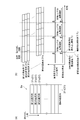
- FIG. It is a figure which shows one Embodiment of the image acquisition apparatus which concerns on this invention. It is a figure which shows an example of an image pick-up element, (a) shows the light-receiving surface of an image pick-up element, (b) shows the relationship between rolling reading in an image pick-up element, irradiation of instantaneous light, etc.
- FIG. It is a figure which shows an example of the scan of the image acquisition area
- FIG. 1 is a diagram showing an embodiment of an image acquisition apparatus according to the present invention.
- the image acquisition apparatus 1 includes a stage 2 on which a sample S is placed, a light source 3 (light emitting means) that irradiates instantaneous light toward the sample, and a sample S on the stage 2.
- the light guide optical system 5 including the objective lens 25 arranged in such a manner and the image sensor 6 that captures the light image of the sample S guided by the light guide optical system 5 are provided.
- the image acquisition apparatus 1 also includes a stage drive unit 11 that moves the visual field position of the objective lens 25 with respect to the sample S, an objective lens drive unit 12 (drive unit) that changes the focal position of the objective lens 25 with respect to the sample S, and a light source.
- a light source control unit 13 control unit that controls the image processing unit 14 and an image processing unit 14.
- the sample S observed by the image acquisition device 1 is a biological sample such as tissue cells, for example, and is placed on the stage 2 in a state of being sealed in a slide glass.
- the light source 3 is disposed on the bottom surface side of the stage 2.
- a flash lamp type light source such as a laser diode (LD), a light emitting diode (LED), a super luminescent diode (SLD), or a xenon flash lamp is used.
- the light guide optical system 5 includes an illumination optical system 21 disposed between the light source 3 and the stage 2 and a microscope optical system 22 disposed between the stage 2 and the image sensor 6.
- the illumination optical system 21 has a Koehler illumination optical system composed of, for example, a condenser lens 23 and a projection lens 24.
- the illumination optical system 21 guides light from the light source 3 and irradiates the sample S with uniform light. ing.
- the microscope optical system 22 includes an objective lens 25 and an imaging lens 26 disposed on the rear stage side (imaging element 6 side) of the objective lens 25, and guides the optical image of the sample S to the imaging element 6.
- the light image of the sample S is an image by transmitted light in the case of bright field illumination, scattered light in the case of dark field illumination, and light emission (fluorescence) in the case of light emission measurement. Moreover, the image by the reflected light from the sample S may be sufficient.
- the light guide optical system 5 an optical system corresponding to image acquisition of a transmitted light image, a scattered light image, and a light emission (fluorescence) image of the sample S can be employed.
- the image sensor 6 is a two-dimensional image sensor having a plurality of pixel columns and capable of rolling readout.
- An example of such an image sensor 6 is a CMOS image sensor.
- a pixel column 31 (first pixel column 31 1 , second pixel) in which a plurality of pixels are arranged in a direction perpendicular to the readout direction.
- a plurality of pixel columns 31 2 , third pixel columns 31 3 ,... Nth pixel column 31 N ) are arranged in the reading direction.
- exposure and readout are sequentially performed for each pixel column, so that the exposure period and the readout period in each pixel column are different from each other.
- the stage drive unit 11 is configured by a motor such as a stepping motor (pulse motor) or an actuator such as a piezo actuator.
- the stage drive unit 11 drives the stage 2 in the XY directions with respect to a plane having a predetermined angle (for example, 90 degrees) with respect to a plane orthogonal to the optical axis of the objective lens 25.
- a predetermined angle for example, 90 degrees
- the sample S is imaged at a high magnification such as 20 times or 40 times.
- the field of view V of the objective lens 25 is small with respect to the sample S, and the region where an image can be acquired by one imaging is also small with respect to the sample S as shown in FIG. Therefore, in order to image the entire sample S, it is necessary to move the visual field V of the objective lens 25 with respect to the sample S.
- the image acquisition region 32 is set so as to include the sample S with respect to the sample container (for example, a slide glass) holding the sample S, and the image acquisition region 32 and the objective lens 25 on the sample S are set. Based on the field of view V, the positions of the plurality of divided regions 33 are set. Then, by capturing a part of the sample S corresponding to the divided region 33 to obtain partial image data corresponding to the divided region 33, the field of view V of the objective lens 25 is set to the position of the divided region 33 to be imaged next. Then, image capturing is performed again to acquire partial image data. At this time, the stage drive unit 11 continues to drive the stage 2 at a constant speed. Thereafter, in the image acquisition apparatus 1, this operation is repeatedly executed, and the image processing unit 14 synthesizes the acquired partial image data to form the entire image of the sample S (synthesized image data).
- the objective lens driving unit 12 is configured by a motor such as a stepping motor (pulse motor) or an actuator such as a piezo actuator, similarly to the stage driving unit 11.
- the objective lens driving unit 12 drives the objective lens 25 in the Z direction along the optical axis of the objective lens 25. Thereby, the focal position of the objective lens 25 with respect to the sample S moves.
- the light source controller 13 emits instantaneous light from the light source 3 as shown in FIG. That is, first, the imaging device 6 sequentially performs exposure and readout in the order of the first pixel column 31 1 , the second pixel column 31 2 , the third pixel column 31 3 ... Nth pixel column 31 N. Go. Then, the image pickup device 6 outputs a trigger signal to the light source control unit 13 after the exposure start T 1 of the N-th pixel column 31 N.
- the light source control unit 13 starts irradiation of instantaneous light from the light source 3 based on the trigger signal output from the image sensor 6. At this time, there is a predetermined period (F 1 -T 1 ) from the exposure start T 1 of the Nth pixel column 31 N that starts the exposure last to the instantaneous light irradiation start F 1 . Subsequently, the light source control unit 13 ends the irradiation of the instantaneous light from the light source 3. At this time, there is a predetermined period (T 2 ⁇ F 2 ) from the end F 2 of the instantaneous light irradiation to the reading start T 2 of the first pixel column 311 that starts the exposure first.
- the objective lens driving unit 12 causes first the first pixel column 31 1 of the read start T 2 after to start reading, then start driving to focus position of the objective lens 25 in the divided region 33 for capturing . Subsequently, the objective lens driving unit 12 ends the driving of the objective lens 25. At this time, the last in a predetermined period of time until the start of exposure of the pixel rows 31 N N-th exposure is started from the driving end of the objective lens 25 is present.
- the in-focus position for example, an in-focus position or a focus map acquired for each divided region 33 prior to imaging of the sample S can be used.
- the stage driving unit 11 drives the stage 2 at a speed at which partial image data of the sample S in each divided region 33 can be acquired by, for example, irradiation of each instantaneous light from the light source 3.
- the image sensor 6 since the image sensor 6 performs rolling readout, noise can be reduced compared with, for example, global readout, and an image can be acquired with a sufficient S / N ratio even when the optical image of the sample S is weak. Is possible.
- the sample S since the sample S is irradiated with the instantaneous light from the light source 3 during the period in which all the pixel columns necessary for imaging by the image sensor 6 are exposed, the timing of receiving the light image of the sample S in each pixel column is the same. Thus, it is possible to acquire a still image in which distortion is suppressed.
- the light source control unit 13 starts the irradiation of the instantaneous light from the light source 3 based on the trigger signal from the image sensor 6, and finally starts the exposure T 1 of the Nth pixel column 31 N that starts the exposure. Since there is a predetermined period (F 1 -T 1 ) from the start of irradiation of instantaneous light F 1 to the light source 3, the instantaneous light is more reliably emitted during the period in which all the pixel columns of the image sensor 6 are exposed. Can be irradiated to the sample S.
- the end of instantaneous light irradiation ends. If the delay light reaching the image sensor 6 with a delay after the presence (for example, when acquiring the fluorescence of the sample S) But during a predetermined time period even in the first pixel column 31 1 (T 2 -F 2) Since the delayed light is received, the light image of the sample S can be received under the same conditions in all the pixel columns of the image sensor 6.
- the objective lens driving unit 12 performs focusing of the objective lens 25 using a period in which each pixel row does not capture the optical image of the sample S, it is possible to speed up still image acquisition. Furthermore, since there is a predetermined period from the end of driving of the objective lens 25 to the start of exposure of the Nth pixel column that starts the exposure at the end, the influence of vibration due to the driving of the objective lens 25 can be reduced when acquiring image data. .
- the present invention is not limited to the above embodiment.
- the light source control unit 13 starts irradiating the instantaneous light from the light source 3 based on the trigger signal output from the image sensor 6, but the light source control unit 13 is independent of the image sensor 6. It is finally first to start irradiation of the instantaneous light from the light source 3 during the first period until the start of the read pixel column 31 1 to start reading from the start of exposure of the pixel rows 31 N N-th exposure is started Good. Even in this case, it is possible to acquire a still image in which distortion is suppressed.
- the image pickup element 6 has output a trigger signal after the exposure start T 1 of the last pixel row 31 of the N-th exposure is started N to the light source control unit 13, starts the last exposure the exposure start T 1 simultaneously with the trigger signal of the pixel rows 31 N of the N which may be output to the light source control unit 13.
- the light source control unit 13 performs a predetermined period (T 2 ⁇ F 2 ) from the end of instantaneous light irradiation F 2 to the start of reading T 2 of the first pixel column 31 1 that starts reading first.
- the light source control unit 13 may first be terminated irradiation of the first pixel column 31 1 of the read start T 2 simultaneously instant light to start reading .
- the sample S can be irradiated with the instantaneous light during the period in which all the pixel columns of the image sensor 6 are exposed.
- the objective lens driving unit 12 for the duration of the first from the first pixel column 31 1 of the read start to start reading start exposure of the last pixel row 31 of the N to start reading to N
- the objective lens driving unit 12 may drive the objective lens 25 to the in-focus position during a period other than the above.
- the objective lens driving unit 12 has completed the driving of the objective lens 25 so that a predetermined period of time until the start of exposure of the pixel rows 31 N of the N to finally start reading from the drive end of the objective lens 25 is present and, with the last exposure start of the N pixel columns 31 N to start reading and may end the driving of the objective lens 25 at the same time.
- instantaneous light is emitted from the light source 3, but continuous light (CW light) may be emitted from the light source 3, and a shutter may be provided between the light source 3 and the sample S.
- the light emitting means is composed of the light source 3 and the shutter, and the light source control unit 13 controls the opening and closing of the shutter, so that the instantaneous light is sampled during the period in which all the pixel columns of the image sensor 6 are exposed. S can be irradiated.
- the objective lens driving unit 12 moves the objective lens 25 in the optical axis direction, thereby moving the focal position of the objective lens 25 with respect to the sample S in the optical axis direction of the objective lens 25.
- the stage drive unit 11 may move the stage 2 in the optical axis direction of the objective lens 25 to move the focal position of the objective lens 25 with respect to the sample S in the optical axis direction of the objective lens 25.
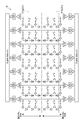
- the column 31 N is configured as a group of pixel columns
- the plurality of pixel columns 31 constituting the light receiving surface 6a of the image sensor 6 are a plurality of pixel columns as shown in FIG.
- the first pixel column group 31a and the second pixel column group 31b may be divided into the first pixel column group 31a and the second pixel column group 31b, and the first pixel column group 31a and the second pixel column group 31b may be read out.
- the reading direction of the first pixel column group 31a and the reading direction of the second pixel column group 31b may be set to be opposite to each other.
- the first pixel column group 31a and the second pixel column group 31b may be sequentially read from the center pixel column to the end pixel column, or alternatively, the first pixel column group 31a and the second pixel column group 31b may be sequentially read.
- data may be sequentially read from the end pixel column to the central pixel column.
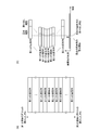
- FIGS. The relationship between the configuration of the light receiving surface 6a and the exposure / readout period at this time is shown in FIGS.
- the light source control unit 13 receives the light receiving surface 6a.
- the light source 3 emits instantaneous light during the period until the start of reading of the ⁇ 1 pixel column.
- the light source control unit 13 6a which starts exposure at the end of the first 1-n, 2-n pixel array starting at the end of the light receiving surface 6a.
- the light source 3 irradiates the instantaneous light during the period until the reading of the pixel array 2-1 starts. In this case as well, since the sample S can be irradiated with the instantaneous light during the period in which all the pixel columns of the image sensor 6 are exposed, it is possible to acquire a still image in which distortion is suppressed. .
- SYMBOLS 1 ... Image acquisition device, 2 ... Stage, 3 ... Light source (light emission means), 5 ... Light guide optical system, 6 ... Image pick-up element, 11 ... Stage drive part (drive part), 12 ... Objective lens drive part (drive part) , 13... Light source control unit (control unit), 14... Image processing unit, 25... Objective lens, 31.
Landscapes
- Physics & Mathematics (AREA)
- Engineering & Computer Science (AREA)
- Multimedia (AREA)
- General Physics & Mathematics (AREA)
- Chemical & Material Sciences (AREA)
- Analytical Chemistry (AREA)
- Optics & Photonics (AREA)
- Signal Processing (AREA)
- Computer Vision & Pattern Recognition (AREA)
- Theoretical Computer Science (AREA)
- Microscoopes, Condenser (AREA)
Priority Applications (4)
| Application Number | Priority Date | Filing Date | Title |
|---|---|---|---|
| EP14857047.6A EP3064982B1 (en) | 2013-11-01 | 2014-01-28 | Image acquisition device and image acquisition method for image acquisition device |
| US15/030,198 US10422987B2 (en) | 2013-11-01 | 2014-01-28 | Image acquisition device and image acquisition method for image acquisition device |
| DK14857047.6T DK3064982T3 (da) | 2013-11-01 | 2014-01-28 | Billedopfangningsanordning og billedopfangningsfremgangsmåde til billedopfangningsanordning |
| CN201480058614.3A CN105683806B (zh) | 2013-11-01 | 2014-01-28 | 图像取得装置以及图像取得装置的图像取得方法 |
Applications Claiming Priority (2)
| Application Number | Priority Date | Filing Date | Title |
|---|---|---|---|
| JP2013-228606 | 2013-11-01 | ||
| JP2013228606A JP6134249B2 (ja) | 2013-11-01 | 2013-11-01 | 画像取得装置及び画像取得装置の画像取得方法 |
Publications (1)
| Publication Number | Publication Date |
|---|---|
| WO2015064117A1 true WO2015064117A1 (ja) | 2015-05-07 |
Family
ID=53003741
Family Applications (1)
| Application Number | Title | Priority Date | Filing Date |
|---|---|---|---|
| PCT/JP2014/051805 Ceased WO2015064117A1 (ja) | 2013-11-01 | 2014-01-28 | 画像取得装置及び画像取得装置の画像取得方法 |
Country Status (7)
| Country | Link |
|---|---|
| US (1) | US10422987B2 (enExample) |
| EP (1) | EP3064982B1 (enExample) |
| JP (1) | JP6134249B2 (enExample) |
| CN (1) | CN105683806B (enExample) |
| DK (1) | DK3064982T3 (enExample) |
| HU (1) | HUE058663T2 (enExample) |
| WO (1) | WO2015064117A1 (enExample) |
Families Citing this family (4)
| Publication number | Priority date | Publication date | Assignee | Title |
|---|---|---|---|---|
| JP6812149B2 (ja) * | 2016-06-30 | 2021-01-13 | オリンパス株式会社 | 走査型顕微鏡、及び、走査型顕微鏡の制御方法 |
| JP6842387B2 (ja) * | 2017-08-31 | 2021-03-17 | 浜松ホトニクス株式会社 | 画像取得装置及び画像取得方法 |
| CN108169783A (zh) * | 2018-02-26 | 2018-06-15 | 苏州大学 | 一种辐射空间剂量分布的实时测量装置及测量方法 |
| CN109669264A (zh) * | 2019-01-08 | 2019-04-23 | 哈尔滨理工大学 | 基于灰度梯度值的自适应自动聚焦方法 |
Citations (7)
| Publication number | Priority date | Publication date | Assignee | Title |
|---|---|---|---|---|
| JPS63191063A (ja) | 1987-02-03 | 1988-08-08 | Sumitomo Electric Ind Ltd | 顕微鏡画像の処理方式 |
| JP2000501844A (ja) | 1995-07-19 | 2000-02-15 | モルフォメトリックス テクノロジーズ インク. | 顕微鏡スライドの自動走査 |
| JP2003043363A (ja) * | 2001-07-27 | 2003-02-13 | Olympus Optical Co Ltd | 共焦点顕微鏡 |
| JP2003222801A (ja) | 2002-01-29 | 2003-08-08 | Olympus Optical Co Ltd | 顕微鏡画像撮影装置 |
| WO2006098443A1 (ja) * | 2005-03-17 | 2006-09-21 | Hamamatsu Photonics K.K. | 顕微鏡画像撮像装置 |
| JP2012108184A (ja) * | 2010-11-15 | 2012-06-07 | Sony Corp | 焦点位置情報検出装置、顕微鏡装置及び焦点位置情報検出方法 |
| JP2012138068A (ja) * | 2010-12-08 | 2012-07-19 | Canon Inc | 画像生成装置 |
Family Cites Families (15)
| Publication number | Priority date | Publication date | Assignee | Title |
|---|---|---|---|---|
| AU3897500A (en) * | 1999-03-19 | 2000-10-09 | Parker Hughes Institute | Vanadium (iv) complexes containing catacholate ligand and having spermicidal activity |
| US7218810B2 (en) * | 2001-09-27 | 2007-05-15 | Bio-Rad Laboratories, Inc. | Biochemical assay detection in a liquid receptacle using a fiber optic exciter |
| TW552803B (en) * | 2002-01-18 | 2003-09-11 | Nucam Corp | Image pickup apparatus and exposure control method therefor |
| JP2003270545A (ja) * | 2002-03-14 | 2003-09-25 | Olympus Optical Co Ltd | 光学スキャニングステージ |
| DE60324656D1 (de) | 2003-01-15 | 2008-12-24 | Negevtech Ltd | Verfahren und Gerät zur schnellen on-line und elektro-optischen Defekterkennung an Wafern |
| CA2574343C (en) * | 2004-07-23 | 2012-05-01 | Paul Donders | Method and apparatus for fluorescent confocal microscopy |
| US20070022380A1 (en) * | 2005-07-20 | 2007-01-25 | Microsoft Corporation | Context aware task page |
| JP4917331B2 (ja) * | 2006-03-01 | 2012-04-18 | 浜松ホトニクス株式会社 | 画像取得装置、画像取得方法、及び画像取得プログラム |
| JP2007256119A (ja) * | 2006-03-23 | 2007-10-04 | Fujitsu Ltd | 検査装置、積層装置、及び検査方法 |
| JP4641275B2 (ja) | 2006-03-29 | 2011-03-02 | 東レエンジニアリング株式会社 | 自動外観検査装置及び自動外観検査方法 |
| JP4823743B2 (ja) * | 2006-04-03 | 2011-11-24 | 三星電子株式会社 | 撮像装置,及び撮像方法 |
| JP4102842B1 (ja) * | 2006-12-04 | 2008-06-18 | 東京エレクトロン株式会社 | 欠陥検出装置、欠陥検出方法、情報処理装置、情報処理方法及びそのプログラム |
| JP6136085B2 (ja) | 2011-10-05 | 2017-05-31 | ソニー株式会社 | 画像取得装置、画像取得方法、およびコンピュータプログラム |
| CN102854615B (zh) * | 2012-04-27 | 2015-07-22 | 麦克奥迪实业集团有限公司 | 一种对显微切片的全自动扫描系统及方法 |
| EP2920634A4 (en) * | 2012-11-16 | 2016-06-22 | Molecular Devices Llc | SYSTEM AND METHOD FOR RECORDING IMAGES WITH A SHUTTER CAMERA DURING ASYNCHRONOUS SEQUENCING OF MICROSCOPE DEVICES |
-
2013
- 2013-11-01 JP JP2013228606A patent/JP6134249B2/ja active Active
-
2014
- 2014-01-28 WO PCT/JP2014/051805 patent/WO2015064117A1/ja not_active Ceased
- 2014-01-28 HU HUE14857047A patent/HUE058663T2/hu unknown
- 2014-01-28 DK DK14857047.6T patent/DK3064982T3/da active
- 2014-01-28 EP EP14857047.6A patent/EP3064982B1/en active Active
- 2014-01-28 US US15/030,198 patent/US10422987B2/en active Active
- 2014-01-28 CN CN201480058614.3A patent/CN105683806B/zh active Active
Patent Citations (7)
| Publication number | Priority date | Publication date | Assignee | Title |
|---|---|---|---|---|
| JPS63191063A (ja) | 1987-02-03 | 1988-08-08 | Sumitomo Electric Ind Ltd | 顕微鏡画像の処理方式 |
| JP2000501844A (ja) | 1995-07-19 | 2000-02-15 | モルフォメトリックス テクノロジーズ インク. | 顕微鏡スライドの自動走査 |
| JP2003043363A (ja) * | 2001-07-27 | 2003-02-13 | Olympus Optical Co Ltd | 共焦点顕微鏡 |
| JP2003222801A (ja) | 2002-01-29 | 2003-08-08 | Olympus Optical Co Ltd | 顕微鏡画像撮影装置 |
| WO2006098443A1 (ja) * | 2005-03-17 | 2006-09-21 | Hamamatsu Photonics K.K. | 顕微鏡画像撮像装置 |
| JP2012108184A (ja) * | 2010-11-15 | 2012-06-07 | Sony Corp | 焦点位置情報検出装置、顕微鏡装置及び焦点位置情報検出方法 |
| JP2012138068A (ja) * | 2010-12-08 | 2012-07-19 | Canon Inc | 画像生成装置 |
Non-Patent Citations (1)
| Title |
|---|
| See also references of EP3064982A4 |
Also Published As
| Publication number | Publication date |
|---|---|
| DK3064982T3 (da) | 2022-04-11 |
| US10422987B2 (en) | 2019-09-24 |
| JP2015087723A (ja) | 2015-05-07 |
| EP3064982A4 (en) | 2017-11-15 |
| US20160252717A1 (en) | 2016-09-01 |
| EP3064982A1 (en) | 2016-09-07 |
| HUE058663T2 (hu) | 2022-09-28 |
| CN105683806B (zh) | 2019-01-01 |
| CN105683806A (zh) | 2016-06-15 |
| JP6134249B2 (ja) | 2017-05-24 |
| EP3064982B1 (en) | 2022-02-23 |
Similar Documents
| Publication | Publication Date | Title |
|---|---|---|
| JP6266601B2 (ja) | 画像取得装置、試料のフォーカスマップを作成する方法及びシステム | |
| JP6154291B2 (ja) | 画像取得装置及び画像取得装置の画像取得方法 | |
| JP5639670B2 (ja) | 画像取得装置及び撮像装置 | |
| CN105143954B (zh) | 图像取得装置、取得试样的对准焦点信息的方法以及系统 | |
| JP6134249B2 (ja) | 画像取得装置及び画像取得装置の画像取得方法 | |
| WO2019123869A1 (ja) | 画像取得装置及び画像取得方法 | |
| JP5848596B2 (ja) | 画像取得装置及び画像取得装置のフォーカス方法 | |
| JP6496772B2 (ja) | 画像取得装置及び画像取得方法 | |
| WO2014112084A1 (ja) | 画像取得装置及び画像取得装置のフォーカス方法 | |
| JP5296861B2 (ja) | 画像取得装置及び画像取得装置のフォーカス方法 | |
| CN117631249A (zh) | 线扫共聚焦扫描光场显微成像装置及方法 | |
| JP2008051772A (ja) | 蛍光画像取得装置、及び蛍光画像取得方法 | |
| JP6240056B2 (ja) | 画像取得装置及び撮像装置 | |
| JP5770958B1 (ja) | 画像取得装置及び撮像装置 | |
| JP5986041B2 (ja) | 画像取得装置及び画像取得装置のフォーカス方法 | |
| JP6475307B2 (ja) | 画像取得装置、撮像装置、及び算出ユニット | |
| WO2022059442A1 (ja) | 撮像装置および撮像方法 |
Legal Events
| Date | Code | Title | Description |
|---|---|---|---|
| 121 | Ep: the epo has been informed by wipo that ep was designated in this application |
Ref document number: 14857047 Country of ref document: EP Kind code of ref document: A1 |
|
| WWE | Wipo information: entry into national phase |
Ref document number: 15030198 Country of ref document: US |
|
| NENP | Non-entry into the national phase |
Ref country code: DE |
|
| REEP | Request for entry into the european phase |
Ref document number: 2014857047 Country of ref document: EP |
|
| WWE | Wipo information: entry into national phase |
Ref document number: 2014857047 Country of ref document: EP |