WO2015053266A1 - プラント運転訓練装置、制御方法、プログラム及びプラント運転訓練システム - Google Patents
プラント運転訓練装置、制御方法、プログラム及びプラント運転訓練システム Download PDFInfo
- Publication number
- WO2015053266A1 WO2015053266A1 PCT/JP2014/076814 JP2014076814W WO2015053266A1 WO 2015053266 A1 WO2015053266 A1 WO 2015053266A1 JP 2014076814 W JP2014076814 W JP 2014076814W WO 2015053266 A1 WO2015053266 A1 WO 2015053266A1
- Authority
- WO
- WIPO (PCT)
- Prior art keywords
- plant
- interface
- model data
- virtual space
- avatar
- Prior art date
- Legal status (The legal status is an assumption and is not a legal conclusion. Google has not performed a legal analysis and makes no representation as to the accuracy of the status listed.)
- Ceased
Links
Images


Classifications
-
- G—PHYSICS
- G09—EDUCATION; CRYPTOGRAPHY; DISPLAY; ADVERTISING; SEALS
- G09B—EDUCATIONAL OR DEMONSTRATION APPLIANCES; APPLIANCES FOR TEACHING, OR COMMUNICATING WITH, THE BLIND, DEAF OR MUTE; MODELS; PLANETARIA; GLOBES; MAPS; DIAGRAMS
- G09B9/00—Simulators for teaching or training purposes
-
- G—PHYSICS
- G09—EDUCATION; CRYPTOGRAPHY; DISPLAY; ADVERTISING; SEALS
- G09B—EDUCATIONAL OR DEMONSTRATION APPLIANCES; APPLIANCES FOR TEACHING, OR COMMUNICATING WITH, THE BLIND, DEAF OR MUTE; MODELS; PLANETARIA; GLOBES; MAPS; DIAGRAMS
- G09B19/00—Teaching not covered by other main groups of this subclass
- G09B19/003—Repetitive work cycles; Sequence of movements
-
- G—PHYSICS
- G09—EDUCATION; CRYPTOGRAPHY; DISPLAY; ADVERTISING; SEALS
- G09B—EDUCATIONAL OR DEMONSTRATION APPLIANCES; APPLIANCES FOR TEACHING, OR COMMUNICATING WITH, THE BLIND, DEAF OR MUTE; MODELS; PLANETARIA; GLOBES; MAPS; DIAGRAMS
- G09B25/00—Models for purposes not provided for in G09B23/00, e.g. full-sized devices for demonstration purposes
- G09B25/02—Models for purposes not provided for in G09B23/00, e.g. full-sized devices for demonstration purposes of industrial processes; of machinery
Definitions
- the present invention relates to a plant operation training apparatus, a control method, a program, and a plant operation training system.
- Patent Literature 1 describes a simulation device that can learn a route to a destination by displaying an avatar in a 3D virtual space in a plant and moving the avatar by an operator's operation. According to this technology, it is possible to learn the route to the destination while displaying the scenery seen when a person actually walks while moving to the destination and feeling the sense of real distance and realism.
- Patent Document 1 is for learning a route by moving an avatar.
- many plant operation training simulation apparatuses that have existed so far usually select a device provided in the plant by a mouse operation and perform an operation training on the device.
- the present invention provides a plant operation training apparatus, a plant operation training method, and a program capable of solving the above-described problems.
- the plant operation training apparatus obtains human model data indicating a person in the virtual space and operates the operation of the avatar displayed in the virtual space based on the human model data.
- a positional relationship calculation unit that calculates the positional relationship between the avatar and the devices included in the plant that acquires the plant model data indicating the plant in the virtual space and displays the plant model data in the virtual space based on the plant model data;
- a detailed screen display control unit that acquires interface detailed screen model data indicating an interface in a virtual space and displays the interface detailed screen of the devices that satisfy a predetermined condition for the positional relationship based on the interface detailed screen model data; Is provided.
- the control method of the plant operation training apparatus acquires the human model data indicating the person in the virtual space and displays the action of the avatar displayed in the virtual space based on the human model data. Operate to obtain plant model data indicating the plant in the virtual space, calculate the positional relationship between the avatar and the equipment included in the plant displayed in the virtual space based on the plant model data, and determine the positional relationship Interface detailed screen model data indicating the interface in the virtual space is acquired and displayed based on the interface detailed screen model data.
- the program acquires the human model data indicating the person in the virtual space by the computer of the plant operation training apparatus, and displays the action of the avatar displayed in the virtual space based on the human model data.
- the interface detail screen of the device that satisfies a predetermined condition for the relationship is made to function as means for acquiring interface detail screen model data indicating an interface in the virtual space and displaying it based on the interface detail screen model data.
- the plant operation training system acquires the human model data indicating a person in the virtual space and operates the operation of the avatar displayed in the virtual space based on the human model data.
- a positional relationship calculation unit that calculates the positional relationship between the avatar and the devices included in the plant that acquires the plant model data indicating the plant in the virtual space and displays the plant model data in the virtual space based on the plant model data;
- a detailed screen display control unit that acquires interface detailed screen model data indicating an interface in a virtual space and displays the interface detailed screen of devices that satisfy a predetermined condition for the positional relationship based on the interface detailed screen model data; and
- the detailed screen display control unit When the display is started, a parameter acquisition unit that requests a parameter value to be displayed on the interface, a plant operation training apparatus, and a parameter value indicating the state of the equipment included in the plant are calculated, and in response to the request A plant simulation device that transmits the calculated parameter value.
- driving training closer to the actual operation can be performed while grasping the positional relationship with the equipment provided in the plant in the 3D virtual space, thereby obtaining a higher training effect. be able to.
- FIG. 6 is a functional block diagram of a plant operation training apparatus according to first to fifth embodiments of the present invention.
- FIG. 6 is a diagram showing regions on the operation screen of the plant operation training apparatus according to the first to fifth embodiments of the present invention. It is a figure which shows the operation screen of the plant operation training apparatus by 1st embodiment of this invention. It is a figure which shows the processing flow of the plant operation training apparatus by 1st embodiment of this invention. It is a 1st figure used in order to demonstrate the processing flow of the plant operation training apparatus by 1st embodiment of this invention. It is a 2nd figure used in order to demonstrate the processing flow of the plant operation training apparatus by 1st embodiment of this invention.
- FIG. 1 is a schematic functional block diagram of a plant operation training apparatus according to the first to fifth embodiments.
- the configurations described in this block diagram are the same in the second to fifth embodiments described later.
- symbol 1 represents the plant operation training apparatus.
- the plant operation training apparatus 1 can reproduce the plant and the avatar, which is a part of the user, in the 3D virtual space using those 3D model data, and simulate the operation training of the equipment provided in the plant for the user. It is a device that provides functions that can be performed.
- the plant operation training device 1 is, for example, a PC or a server device that can execute a program that realizes this function.
- Reference numeral 2 denotes a plant simulation apparatus.
- the plant simulation device 2 is a device that simulates the behavior of the plant by calculating state quantities such as an output of a gas turbine, a pressure in the compressor, and a temperature provided in the plant.
- the plant simulation apparatus is connected to the plant operation training apparatus 1 via a network.
- the plant operation training apparatus 1 receives a signal indicating the operation content performed by the avatar on the devices, and simulates the behavior of the plant based on the content.
- the signal indicating the operation content includes, for example, information indicating opening / closing of a valve and turning on / off of a certain control device.
- the plant simulation device 2 transmits the calculated state quantity and the like to the plant operation training device 1.
- the user performs an operation simulating causing the avatar of the plant operation training apparatus 1 to check the indicator provided in the plant, and knows what result is obtained by the operation performed by the user through the avatar. In this way, the user can learn the operation of the equipment provided in the plant.
- the plant simulation apparatus 2 is also connected to a training simulation apparatus (not shown) that simulates the central control room.
- the plant simulation apparatus 2 receives a user operation using the simulation apparatus in the central control room and similarly simulates the behavior of the plant.
- the plant operation training apparatus 1 is a part of the plant operation training system configured as described above.
- the plant operation training apparatus 1 includes a display unit 10, an operation unit 20, a virtual space generation unit 30, a storage unit 40, and a communication unit 50.
- the display unit 10 is a monitor such as a PC, a screen projected by a projector, or the like.
- the user looks at the 3D image of the equipment in the plant output to the display unit 10 and performs an operation necessary for training.
- the operation means 20 is a mouse, a game controller, a joystick or the like.
- the user controls the operation of the avatar using these operation means.
- an operation using not only a mouse but also a game controller or a joystick is possible. As a result, the user can smoothly move through the plant represented in the 3D virtual space and can receive training with a more realistic feeling.
- the 3D image provided by the plant operation training device 1 is not an object selected using the operation means 20 so that it can be easily operated even when a large screen is used.
- the operation target interface screen is displayed, and the operation using the game controller is facilitated.
- the virtual space generation unit 30 reads the 3D plant model data and the 3D human model data from the storage unit 40, and reproduces the state of the plant and the avatar in the 3D virtual space. In addition, an operation signal is acquired from the operation unit 20, the avatar is operated according to the user's operation, a 3D image of the place where the avatar has moved is generated, and is output to the display unit 10.
- the virtual space generation unit 30 includes a positional relationship calculation unit 31, a detailed screen display control unit 32, a corresponding part display control unit 33, a detailed screen display selection unit 34, a detailed screen selection setting unit 35, and a parameter acquisition unit 36. Yes.
- the positional relationship calculation unit 31 calculates the positional relationship between the avatar and the devices provided in the plant.
- the equipment provided in the plant refers to large facilities such as turbines and boilers, and operating devices and indicators provided in these facilities.
- the positional relationship refers to the distance between the avatar and the devices, whether the avatar exists in a closed space (such as a room) provided with the devices, or whether the avatar is facing the devices.
- the detailed screen display control unit 32 displays an interface detailed screen of an operation device or a display device in a positional relationship that satisfies the predetermined condition at a predetermined position.
- the interface detail screen is an image enlarged so that the user can read the interface of the operation device or the display device.
- the values of various parameters displayed on the interface are values acquired from the plant simulation apparatus 2.
- the model data of the interface detail screen is stored in the storage unit 40 in association with the position information of the position where the device having the interface is provided.
- Corresponding part display control unit 33 displays a part provided with a display or an operation unit having an interface indicated by the interface detail screen displayed by detailed screen display control part 32 in a manner different from other devices.
- An aspect different from other devices means that only the part is blinked or displayed in a conspicuous color.
- the corresponding part display control unit 33 may display the large facility equipment itself provided with a display device and an operation device in a different manner.
- the detailed screen display selection unit 34 provides a user with a means for selecting an interface detailed screen displayed by the detailed screen display control unit 32. Specifically, the detailed screen display selection unit 34 displays the interface detailed screens of a plurality of devices in a predetermined position on the display unit 10 and selects whether or not to display sequentially from the detailed screen displayed in the foreground. Prompt the user. The detailed screen display selection unit 34 provides a function for preventing display of unnecessary interface details screens of equipment when there are many instruments at a certain plant location.
- the detailed screen selection setting unit 35 provides a function of specifying an interface detail screen of selectable devices displayed by the detailed screen display selection unit 34 and setting the result.
- the detail screen selection setting unit 35 provides a function for setting not to display the interface detail screen of the device that is not used by the user.
- the equipment that is not used by the user is, for example, equipment that determines that a training instructor is unnecessary according to the level of the user who receives plant operation training, or equipment that should be used only in an emergency or emergency.
- the parameter acquisition unit 36 requests the parameter value to be displayed on the interface from the plant simulation apparatus 2 when the detailed screen display control unit 32 starts displaying the interface detailed screen.
- the parameter acquisition unit 36 requests a parameter value via the communication unit 50 and acquires the parameter value from the plant simulation apparatus 2.
- the parameter value is a state quantity such as the pressure and temperature of the plant calculated by the plant simulation apparatus 2.
- the plant simulation apparatus 2 calculates the pressure, temperature, and the like at the position where the gauges and thermometers provided in the plant are provided, and the state quantity is obtained according to the request of the parameter acquisition unit 36.
- the detail screen display control unit 32 displays the interface detail screen of each device in which the parameter value acquired by the parameter acquisition unit 36 is set.
- the parameter acquisition part 36 will transmit the signal which shows the operation content to the plant simulation apparatus 2 via the communication part 50, if a user operates with respect to an operating device via an avatar.
- the storage unit 40 stores plant 3D model data, human 3D model data, equipment interface detail screen model data, and the like. In addition, the setting contents by the detailed screen selection setting unit 35 are also stored. Note that the model data on the device interface detail screen may be 2D image data.
- the communication unit 50 communicates with other devices. The communication part 50 transmits / receives the parameter value information of the plant state quantity, for example.
- the virtual space generation unit 30 is a function provided when a CPU (Central Processing Unit) provided in the plant operation training apparatus 1 executes a program.
- FIG. 2 is a diagram showing each display area on the operation screen of the plant operation training apparatus 1 according to the present embodiment.
- the regions described here are the same in the second to fifth embodiments.
- the position and meaning of displaying the interface detail screen will be described with reference to FIG.
- Reference numeral 104 denotes an area where the detailed screen display control unit 32 displays the interface details screen of the devices. Hereinafter, this area is referred to as an operable area.
- the device interface detail screen displayed in the operable area 104 is a user's operation target.
- Reference numeral 105 denotes an area where the detail screen display selection unit 34 displays the interface detail screen in an overlapping manner. Hereinafter, this area is referred to as a selection area.
- the detailed screen display control unit 32 displays only the interface image of the device selected by the user from the device options displayed in the selection area 105 by the detailed screen display selection unit 34 in the operable area.
- Reference numeral 106 denotes an area for displaying an interface detail screen that is not selected by the user. Hereinafter, this area is referred to as an operation impossible area.
- Reference numeral 107 denotes an interface details screen. In the interface image, an interface of a display device or an operation device is displayed. The user can know the state of the plant by looking at the interface detail screen 107 of the display. The user can operate the device using the operation means 20 on the interface detail screen 107 of the operation device.
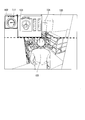
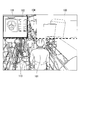
- FIG. 3 is a diagram showing an operation screen of the plant operation training apparatus 1 according to the present embodiment.
- An operation in which the detailed screen display control unit 32 displays the interface detail screen 107 of the operation device or the display device according to the positional relationship calculated by the positional relationship calculation unit 31 will be described with reference to FIG.
- Reference numeral 100 is a 3D image simulating a certain place inside the plant.
- Reference numeral 101 denotes an avatar. It is assumed that the avatar 101 has reached the place 100 in the plant by the operation of the operation means 20 by the user.
- the virtual space generation unit 30 acquires the operation signal from the operation unit 20, the virtual space generation unit 30 calculates the movement distance based on the position before the operation of the avatar 101.
- the movement distance may be calculated, for example, so as to advance a predetermined distance every time a predetermined button is pressed.
- the virtual space generation unit 30 calculates position information of the avatar in the plant every time the avatar 101 moves and outputs it to the memory. In addition, the virtual space generation unit 30 reproduces the scenery of the plant near the position based on the position information of the movement destination of the avatar 101.
- the place 100 is a 3D image generated by the virtual space generation unit 30 in this way.
- the plant 3D model data stored in the storage unit 40 includes position information of the equipment in the plant.
- the positional relationship calculation unit 31 calculates the distance between the avatar 101 and the devices provided in the plant using the respective position information in the plant.
- FIG. 3 it is assumed that a high-pressure feed water flow meter 102 and a high-pressure feed valve rear valve 103 are provided in the vicinity of the place 100.
- the distance between the avatar 101, the high-pressure water supply flow meter 102, and the high-pressure water supply valve rear valve 103 is within a predetermined distance (first threshold).
- the detailed screen display control unit 32 acquires the model data of the interface detailed screen of the high-pressure feed valve rear valve and the high-pressure feed flow meter from the storage unit 40 and displays the interface detail screen 107 in the operable area 104.
- the interface detail screen 107 of the high-pressure feed water flow meter 102 and the interface detail screen 107 of the high-pressure feed valve rear valve 103 are displayed in the operable area 104 so as to overlap the front of the plant 3D image.
- the user can grasp what value the high-pressure feed water flow meter 102 indicates from the interface detail screen 107.
- the user can adjust the opening / closing degree of the high-pressure water supply valve rear valve 103 and change the flow rate by operating the interface detail screen 107 using the operation means 20.
- the mouse when performing a valve opening / closing operation, the mouse is first moved to the vicinity of the 3D image of the valve, the valve is selected by a click operation, and further a valve opening / closing instruction is performed by a click operation or the like.
- a click operation When the operation is completed, it is necessary to close the window by clicking the X mark at the upper right corner of the valve image window.
- the user moves the avatar 101, and the detailed screen display control unit 32 displays the interface details screen of the device just by approaching the device that is the subject of the operation training. There is no need to perform any special operations. Therefore, the user can grasp the positional relationship with the devices and can work on driving training with a more realistic feeling.
- the game controller when used, it is difficult to perform an operation in which the user selects a device to be operated. However, since the interface details screen 107 of the device is displayed only when the avatar 101 approaches the devices as described above, no selection operation is necessary. To move the avatar 101 with the game controller, for example, a joystick is used.
- FIG. 3 the operation when the avatar 101 approaches the device has been described.
- the detailed screen display control unit 32 hides the interface detailed screen 107 when the avatar 101 leaves the device.
- the positional relationship calculation unit 31 calculates the distance between them.
- the detailed screen display control unit 32 hides the interface detailed screen 107 displayed in the operable area 104 when the distance between the avatar 101 and the device is equal to or greater than the second threshold.
- the user can hide the interface detail screen 107 that is not used simply by moving the avatar 101 away from the device, and does not need to perform complicated operations.
- the operation of the operation device displayed on the interface detail screen 107 will be briefly described. In FIG.
- the interface detail screen 107 of the high-pressure feed water flow meter 102 is currently active by a user's predetermined operation. Active means that it is in a state of accepting a user operation.
- the user switches the active interface detail screen 107 by pressing the right key of the cross key of the game controller, for example. Then, the interface detail screen 107 of the high pressure water supply valve rear valve 103 becomes active.
- the user opens and closes the high-pressure water supply valve rear valve 103 using the up and down buttons of the cross key, for example. According to the present embodiment, it is possible to move the avatar, display / hide the device interface, and operate the operation device with a simple operation.
- the display / non-display determination of the interface detail screen 107 is determined by the distance between the avatar 101 and the device, but in addition to that, the orientation of the avatar 101 may be added to the determination. For example, even if the device is provided near the avatar 101, the device provided on the back side of the user is not displayed. Further, even if the device is displayed in the operable area 104, the interface detail screen 107 may be hidden when the avatar 101 faces in another direction. As a result, the user can learn the position where the devices are installed more accurately. In addition, when the equipment is provided in a room, the position information of the avatar 101 is compared with the position information of the room in which the equipment is provided, and when the avatar 101 enters the room, the room is provided. The device interface detail screen 107 may be displayed in the operable area 104. Further, the interface detail screen 107 may be hidden when the avatar 101 leaves the room.
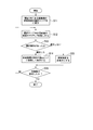
- FIG. 4 is a first diagram showing a processing flow of the display device according to the present embodiment.
- FIG. 5A is a first diagram used for explaining the processing flow of the plant operation training apparatus according to the first embodiment of the present invention.
- FIG. 5B is a second diagram used for explaining the processing flow of the plant operation training apparatus according to the first embodiment of the present invention.
- the positional relationship calculation part 31 acquires the combination of the apparatus (each operation device and indicator) in a plant, and its positional information from the memory
- the position information is three-dimensional coordinate information.
- the positional relationship calculation unit 31 may acquire the position information of the devices of the entire plant, or only the position information of the devices provided within a predetermined distance based on the route along which the avatar 101 moves. You may acquire one after another.
- the positional relationship calculation unit 31 counts the total number of acquired devices and stores it in the memory.
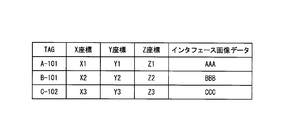
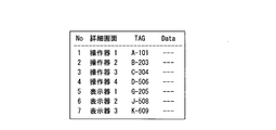
- FIG. 5A is a diagram illustrating an example of a table read by the positional relationship calculation unit 31 in step S1. This table is held in the storage unit 40.
- the positional relationship calculation unit 31 includes an “TAG” field in which the identifier of the device is stored from the table shown in FIG. 5A and an “X coordinate”, “Y coordinate”, and “Z coordinate” column that indicate the position information of the device in the plant. Get the value and store it in memory.
- the virtual space generation unit 30 acquires user operation information from the operation means 20 and moves the avatar 101 to a place corresponding to the operation information.
- the virtual space generation unit 30 reads the 3D model data of the plant from the storage unit 40 and generates a 3D image showing a scene entering the field of view from the position where the avatar 101 has moved. Then, the virtual space generation unit 30 outputs the newly generated 3D image to the display unit 10. In addition, the virtual space generation unit 30 outputs position information of a place where the avatar 101 exists to the memory.
- the positional relationship calculation part 31 acquires the positional information in the plant of the avatar 101 from memory (step S2).
- the positional relationship calculation unit 31 uses the positional information acquired in steps S1 and S2 to determine the avatar 101 and the device i for one of the devices (operator or display) acquired in step S1 (device i).
- the distance i which is the distance of is calculated (step S3).
- the distance i is ⁇ (X2-X1) 2 + (Y2), where (X1, Y1, Z1) is the position information of the place where the avatar 101 exists and (X2, Y2, Z2) is the position information of the device i. It can be obtained by calculating the square root of -Y1) 2 + (Z2-Z1) 2 ⁇ .
- the positional relationship calculation unit 31 compares the distance i calculated in step S3 with a predetermined first threshold (step S4).
- step S4 Yes
- the first threshold is a value used to determine whether or not the avatar 101 displays the interface detail screen 107 of the device i.
- the detailed screen display control unit 32 determines whether the interface detailed screen 107 of the device i indicated by the acquired identifier has already been displayed (step S5).
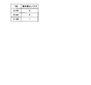
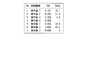
- An example of the determination method in step S5 will be described with reference to FIG. 5B.
- FIG. 5B shows an example of a table that is referred to when the detailed screen display control unit 32 determines whether the interface detailed screen 107 of the device i has already been displayed. In this figure, if the value of the “displayed flag” field is “0”, it indicates that the interface detail screen 107 of the device having the “TAG” field of the record as an identifier is not displayed in the operable area. A value of “1” indicates that the interface image of the device has already been displayed in the operable area.
- step S5 Yes
- the detail screen display control unit 32 does not display the interface detail screen 107 of the device i.
- the case where the interface detail screen 107 of the device i is already displayed may be a case where the avatar 101 approaches the device i and moves back and forth (the range not exceeding the second threshold described later).
- step S5 No
- the detailed screen display control unit 32 stores image data indicating the interface details screen 107 of the operation unit or display corresponding to the identifier of the device i. The data is read from 40 and displayed in the operable area of the display unit 10 (step S6).
- the detailed screen display control unit 32 reads the table of FIG. 5A using the identifier (“TAG”), and acquires the value of the “interface image data” column of the corresponding record. Then, the detailed screen display control unit 32 specifies the image data indicated by this value, and generates the interface detailed screen 107 of the device i based on the specified image data. When the detailed screen display control unit 32 completes these processes, it outputs a signal indicating that the process has been completed to the positional relationship calculation unit 31.
- TAG identifier
- step S10 Yes
- step S4 The case where the distance between the position of the avatar 101 and the position of the device i is smaller than the first threshold in step S4 has been described so far.
- the detailed screen display control unit 32 does not display the interface detailed screen 107 of the device i + 1.
- the positional relationship calculation unit 31 compares the distance i + 1, which is the distance between the avatar 101 and the device i + 1, with the second threshold value (step S7).
- the second threshold is a value used to determine whether or not to hide the interface detail screen 107 when the avatar 101 moves away from the device i.
- step S7 No
- the process for the device i + 1 is completed (the device i + 1 is not particularly performed), and the determination in step S10 is performed.
- the positional relationship calculation unit 31 outputs information indicating the identifier of the device i + 1 to the detailed screen display control unit 32.
- the detailed screen display control unit 32 determines whether or not the interface detailed screen 107 of the device i + 1 indicated by the acquired identifier is already displayed in the operable area (step S8).
- the determination method may be the same as in step S5.
- the positional relationship calculation unit 31 is notified of the completion of the process.
- the detailed screen display control unit 32 displays the interface details screen 107 of the operation device or display device corresponding to the identifier of the device i + 1 displayed in the operable area. Is performed (step S9).
- step S10 When the control for displaying / hiding interface images for all devices is completed as described above, this processing flow ends.
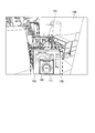
- FIG. 6 is a diagram showing an operation screen of the plant operation training apparatus 1 according to the present embodiment. A method for providing a means by which the detailed screen display selection unit 34 can select the interface detailed screen 107 to the user will be described with reference to FIG.
- FIG. 6 is a 3D image when the avatar 101 is present at the plant location 100. In FIG. 6, it is assumed that the high pressure feed valve rear valve 103 and the high pressure feed water flow meter 102 are provided within a distance smaller than the first threshold value from the avatar 101.
- the detail screen display selection unit 34 displays the interface detail screen 107 of the high-pressure feed water flow meter 102 and the interface detail screen 107 of the high-pressure feed valve rear valve 103 in the selection area 105 of the display unit 10 in an overlapping manner. Further, the detailed screen display selection unit 34 displays, for example, a red frame 111 indicating that it is a target for accepting an operation from the user on the outer frame of the interface detail screen 107 of the device displayed on the forefront.
- the detailed screen display control unit 32 moves and displays the interface detailed screen 107 in the operable area. Further, when the user performs an operation without selecting a device, the detailed screen display selection unit 34 deletes the interface detail screen 107 from the selection area, and displays another interface detail screen 107 displayed below the frontmost screen. To display.
- the predetermined operation may be, for example, pressing a predetermined button of the game controller or performing a click operation with a mouse. Further, when the user performs another predetermined operation indicating that the device is not selected, the detail screen display selection unit 34 deletes the interface detail screen 107 from the selection area 105 and displays the next interface detail screen 107 in the selection area. 105 is displayed on the foreground. The result selected by the user is stored in the storage unit 40 by the detailed screen display selection unit 34.
- the number of interface detail screens 107 displayed in the operable area 104 can be reduced.
- the user can reduce the trouble of selecting a device to be operated from the interface detail screen 107 displayed in the operable area 104.
- the detailed screen display selection unit 34 displays the interface detail screens 107 one by one in the selection area 105 and displays images of different devices one after another at the same position each time selection is completed. Does not need to select a device to be selected with a mouse or the like.
- the detailed screen display selection unit 34 may display the interface detail screen 107 in the selection area 105 when a predetermined operation key is pressed when the user wants to select again.
- the interface detail screen 107 is hidden.
- the interface detail screen 107 is moved to the non-operational area 106 and displayed. It is also possible to display the images in a superimposed manner. In this case, referring to the interface detail screen 107 displayed in the non-operational area 106, the user can grasp what other devices are provided. Furthermore, it is good also as operation
- FIG. The user can display the interface detail screen 107 of the device in the operable area 104 by selecting again the device that is determined to be unnecessary once.
- FIG. 7 is a diagram showing a processing flow of the display device according to the present embodiment.
- the processing described in FIG. 6 will be described in detail using the processing flow of FIG.
- the positional relationship calculation unit 31 acquires the position information of the avatar 101 and the position information of the devices from the memory, calculates these distances, and the distance to the avatar 101 is greater than the first threshold. Identify equipment in a small location. Then, the positional relationship calculation unit 31 outputs information indicating the identifiers of the specified devices to the detailed screen display selection unit 34.
- the detailed screen display selection unit 34 reads the interface detailed screen from the storage unit 40 using the acquired identifier of the device, and displays the interface detailed screen on the selection area 105 (step S11).
- the order of overlapping may be, for example, in the order of identifiers, or may be displayed on the front side closer to the avatar 101.
- Step S11 the detailed screen display selection unit 34 uses, for example, a table shown in FIG.
- a value indicating that “display / do not display” or neither of them is set in the operation area for the device having the identifier is set. If the value in the “operable flag” field is “0”, it indicates that the device has not been set at all. A value of “1” indicates that “display in the operation area” is set for the device. A value of “2” indicates that the device is set to “not display in the operation area”.
- step S11 the detailed screen display selection unit 34 reads this table, selects devices whose “operation possible flag” value is “0”, and displays an interface image in the selection area only for those devices. .
- the detailed screen display selection unit 34 outputs the identifier information to the detailed screen display control unit 32, and the detailed screen display control unit 32 outputs the identifier information to the operable area.
- Devices whose flag value is “2” are not displayed.
- the detailed screen display selection unit 34 displays the interface image of the device indicated by the TAG “A-101” in the selection area.
- the detailed screen display control unit 32 displays the image interface of the device indicated by the TAG “B-101” in the operable area.
- the interface image of the device indicated by the TAG “C-102” has already been set not to be displayed, so it is not displayed anywhere.
- the detail screen display selection unit 34 performs control so that the interface detail screen 107 displayed at the forefront becomes the target of the user's selection operation. Specifically, the detailed screen display selection unit 34 focuses on the interface image to make it active (step S12). Further, the detailed screen display selection unit 34 may display a red frame on the outer peripheral portion of the interface detail screen 107 so that the user can easily understand. Next, the detailed screen display selection unit 34 detects a signal indicating the selection operation by the user from the operation unit 20 and determines whether or not the user has selected to display the interface image of the device i in the operable area ( Step S13).
- the detailed screen display selection unit 34 When the detailed screen display selection unit 34 acquires a signal indicating that the device i is selected, the detailed screen display selection unit 34 outputs the identifier of the device i to the detailed screen display control unit 32. Next, the detailed screen display control unit 32 moves and displays the interface detailed screen 107 of the device i from the selection area 105 to the operable area 104 based on the acquired identifier (step S14). Then, the detailed screen display selection unit 34 records in the storage unit 40 that “display” is selected in the operable area 104 for the device i. For example, in the case of the example of FIG. 8, “1” is set in the “operation possible flag” column of the record having the TAG value indicating the device i.
- the detailed screen display selection unit 34 When the detailed screen display selection unit 34 acquires a signal indicating that the device i is not selected, the detailed screen display selection unit 34 hides the interface image of the device i (step S15). Then, the detailed screen display selection unit 34 records in the storage unit 40 that “not display” is selected in the operable area for the device i. For example, in the case of the example of FIG. 8, “2” is set in the “operation possible flag” field of the record having the TAG value indicating the device i.
- FIG. 9 is a diagram showing a setting screen of the plant operation training apparatus 1 according to the present embodiment.
- FIG. 9 shows an example of a setting screen on which a user who acts as an instructor for plant operation training can set a device for displaying the interface detail screen 107 in the selection area 105.
- Reference numeral 110 indicates a setting screen.
- Reference numeral 112 denotes a check box group that can set display / non-display in the selection area 105 for each device.
- the device “operator 1” corresponding to the check box 112a checked by the user is a device to be displayed in the selection area by the detailed screen display selection unit 34.
- the device “display 3” corresponding to the check box 112b not checked by the user is a device that the detailed screen display selection unit 34 does not display in the selection area. Even if the “operator 1” is checked, the detailed screen display selection unit 34 may be configured to “operate” after the user has set whether or not to display the “operator 1” in the operable area 104.
- the interface detail screen 107 of “device 1” is not displayed in the selection area 105.
- Reference numeral 108 denotes an OK button.
- the detailed screen selection setting unit 35 stores the content set by the user on this screen in the table shown in FIG. Then, the setting screen 110 is closed.
- An example of the operation in which the detailed screen selection setting unit 35 stores the setting value in the table will be described using the table shown in FIG.
- values may be set as follows. Originally, when the value of the “operation possible flag” is “0” or “1” for the device, the value is maintained as it is. When the value is “2”, the detailed screen selection setting unit 35 sets “0”.
- the value in the “operable flag” column is “2” originally, it means that the device has been set not to be displayed in the operable area. However, it is considered appropriate to check the “display” check box on the setting screen 110 for such a device again to give the user an opportunity to select whether or not to display in the operation selection area. Because. Further, when the user removes the check from the device that has been checked up to now, the detailed screen selection setting unit 35 sets “2” in the “operation possible flag” field. By setting “2”, the interface image of the device is not displayed in the selection area or the operable area.
- Numeral 109 indicates a cancel button.
- the detailed screen selection setting unit 35 closes the setting screen 110 without updating the table in the storage unit 40.
- This function can be used, for example, to select a device to be displayed in accordance with the training content of a user who is trained by a driving training instructor. For example, when the level of a user who is trained is a beginner, it is desirable to display only the interface images of the minimum necessary devices, but this is possible by using the settings of this embodiment. This function can also limit the display of devices that are not normally used. Note that this embodiment can be used in combination with the first embodiment. In that case, for example, control is performed as follows.
- the detailed screen display control unit 32 refers to the table in which the detailed screen selection setting unit 35 records whether or not to display for each device.
- “display” is set in this table. Only the image of the connected device is displayed.
- an interface image of a necessary device can be displayed to a user who does not have knowledge of selecting the necessary device from the selection area.
- FIG. 10 is a diagram showing an operation screen of the plant operation training apparatus 1 according to the present embodiment.
- the operation in which the corresponding part display control unit 33 displays the part provided with the device corresponding to the interface image selected by the user in a manner different from other devices will be described with reference to FIG.
- FIG. 10 is a 3D image showing that the interface detail screen 107 of the high-pressure water supply valve rear valve 103 is displayed in the operable area 104 when the avatar 101 moves to the location 100 in the plant by the user's operation.
- the high-pressure water supply valve rear valve 103 is provided within a distance smaller than the first threshold value with the avatar 101, and reference numeral 113 indicates a portion where the high-pressure water supply valve rear valve 103 is provided.
- the corresponding part display control unit 33 displays a red frame on the outer peripheral portion of the interface detail screen 107. Then, the corresponding part display control unit 33 makes the part 113 provided with the high-pressure water supply valve rear valve 103 blink to make it easy for the user to see. Moreover, when an avatar approaches a predetermined distance from a large equipment such as a turbine equipped with many instruments, the corresponding part display control unit 33 first displays the large equipment in a different color or the like. It may be displayed prominently. When the user selects a device in the operable area 104, the corresponding part display control unit 33 may blink and display the part provided with the device.
- the user can know where the device to be operated is provided. With such an operation, it is possible to learn the operation method while grasping the installation location of the equipment, so that it is possible to expect the same high training effect as when performing a practical training using an actual plant.
- FIG. 11 is a diagram showing a processing flow of the display device according to the present embodiment.
- the processing described in FIG. 10 will be described in detail using the processing flow in FIG.
- the avatar 101 moves in accordance with a user instruction and exists at a location 100 in the plant.
- an interface detail screen 107 of devices within a distance range smaller than the first threshold is displayed in the operable area 104 with the avatar 101.
- the operation means 20 when the user operates the operation means 20, one is selected from the interface details screen 107 displayed in the operable area 104.
- the corresponding part display control unit 33 activates the interface detail screen 107 and performs control to display a red frame on the outer peripheral portion (step S31).
- the corresponding part display control unit 33 blinks and displays the 3D image of the device corresponding to the selected interface detail screen 107.
- the corresponding part display control unit 33 specifies a program for generating a 3D image of the device using the identifier of the device corresponding to the selected interface detail screen 107.
- the corresponding part display control unit 33 instructs the specified program to change or blink the color of the part (step S32).
- an RGB value indicating the changed color may be specified in a program for generating a 3D image, and the device may be blinked and the color may be changed.
- it is preferable to select a conspicuous color so that the color to be changed or blinked is easily noticeable by the user.
- the corresponding part display control unit 33 detects whether another interface display screen displayed in the operable area is selected by the user's selection operation (step S33). When another interface screen is selected, the processing from step S31 is repeated. In addition, for a non-selected device, an instruction is given to the program that generates a 3D image of the device to return to the original display mode.
- FIG. 12A is a first diagram showing parameter values displayed on the interface details screen of the plant operation training apparatus 1 according to the present embodiment.
- FIG. 12B is a second diagram showing parameter values displayed on the interface details screen of the plant operation training apparatus 1 according to the present embodiment.
- 12A and 12B when the avatar 101 exists at the location 100, the storage unit 40 displays the list of devices provided at a distance closer to the avatar 101 than the first threshold and the interface details screen of each device. The parameter value which has is shown.
- FIG. 12A shows the parameter value values of each device before the interface detail screen 107 of each device is displayed in the operable area.
- the storage unit 40 does not yet have a parameter value to be displayed on the interface of each device.
- FIG. 12B shows parameter values of each device when the interface detail screen 107 of each device is displayed in the operable area.
- the storage unit 40 has each parameter value acquired from the plant simulation apparatus 2.
- the processing capacity of the CPU of the plant operation training apparatus 1 is consumed for communication processing, and the calculation load increases.
- 3D image generation processing for driving training is affected, and the 3D image display cannot be displayed smoothly.
- only necessary parameter values are extracted and communicated to reduce the communication load, thereby reducing the calculation load of the plant operation training apparatus 1 that displays the 3D virtual plant image. Thereby, the effect that 3D image display can be displayed smoothly is acquired.
- the plant operation training system which consists of the plant operation training apparatus 1 and the plant simulation apparatus 2 (and the training simulator apparatus of the central control room) is designed on the assumption that a plurality of users use it at the same time.
- the user A trains the operation method of the device A using the plant operation training apparatus 1A
- another user B trains the operation method of the device B using the plant operation training apparatus 1B
- the plant operation training apparatuses 1A and 1B are both connected to the plant simulation apparatus 2 via a network.
- the plant simulation apparatus 2 influences the operations A and B on the state of the plant. It calculates and transmits the result to the plant operation training apparatuses 1A and 1B. In this way, this system provides a function of operation training in which a single plant is operated at a plurality of locations at the same time.
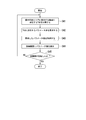
- FIG. 13 is a first diagram illustrating a processing flow of the display device according to the present embodiment.
- the processing described in FIGS. 12A and 12B will be described using the processing flow of FIG.
- the processing flow is executed immediately before the detailed screen display control unit 32 displays the interface detailed screen of the devices within the distance range smaller than the first threshold value in the operable area 104 with the avatar 101.
- the detailed screen display control unit 32 acquires the identifier (TAG) of one device among the devices to be displayed on the interface detailed screen 107 in the operable area 104 in the same manner as step S4 in FIG.
- TAG identifier
- the parameter acquisition unit 36 requests the latest parameter value for the TAG from the plant simulation device 2 via the communication unit 50 (step S42).
- the plant simulation apparatus 2 calculates the plant state quantity at each time and holds it for each TAG information.
- the plant simulation apparatus 2 transmits the latest parameter value in response to the request from the parameter acquisition unit 36.
- the parameter acquisition unit 36 acquires the parameter value of the device corresponding to the TAG requested from the plant simulation device 2 via the communication unit 50 (step S43).
- the parameter acquisition unit 36 then outputs the acquired parameter value to the detailed screen display control unit 32.
- the detailed screen display control unit 32 outputs the interface detailed screen 107 including the acquired parameter value to the operable area (step S44).
- the detailed screen display control unit 32 determines whether or not the above processing has been performed for all devices to be displayed in the operable area 104 (step S45), and repeats the processing from steps S41 to S44 for all devices.
- the plant operation training apparatus 1 described above has a computer inside.
- Each process of the plant operation training apparatus 1 described above is stored in a computer-readable recording medium in the form of a program, and the above process is performed by the computer reading and executing this program.
- the computer-readable recording medium means a magnetic disk, a magneto-optical disk, a CD-ROM, a DVD-ROM, a semiconductor memory, or the like.
- the computer program may be distributed to the computer via a communication line, and the computer that has received the distribution may execute the program.
- the program may be for realizing a part of the functions described above. Furthermore, what can implement
- the operation training closer to the actual operation is performed while grasping the positional relationship with the equipment provided in the plant. Can achieve higher training effects.
Landscapes
- Engineering & Computer Science (AREA)
- Business, Economics & Management (AREA)
- Theoretical Computer Science (AREA)
- Physics & Mathematics (AREA)
- Educational Administration (AREA)
- Educational Technology (AREA)
- General Physics & Mathematics (AREA)
- Entrepreneurship & Innovation (AREA)
- Processing Or Creating Images (AREA)
Applications Claiming Priority (2)
| Application Number | Priority Date | Filing Date | Title |
|---|---|---|---|
| JP2013213698A JP6159217B2 (ja) | 2013-10-11 | 2013-10-11 | プラント運転訓練装置、制御方法、プログラム及びプラント運転訓練システム |
| JP2013-213698 | 2013-10-11 |
Publications (1)
| Publication Number | Publication Date |
|---|---|
| WO2015053266A1 true WO2015053266A1 (ja) | 2015-04-16 |
Family
ID=52813082
Family Applications (1)
| Application Number | Title | Priority Date | Filing Date |
|---|---|---|---|
| PCT/JP2014/076814 Ceased WO2015053266A1 (ja) | 2013-10-11 | 2014-10-07 | プラント運転訓練装置、制御方法、プログラム及びプラント運転訓練システム |
Country Status (2)
| Country | Link |
|---|---|
| JP (1) | JP6159217B2 (enExample) |
| WO (1) | WO2015053266A1 (enExample) |
Cited By (6)
| Publication number | Priority date | Publication date | Assignee | Title |
|---|---|---|---|---|
| KR20180132132A (ko) | 2016-05-23 | 2018-12-11 | 미츠비시 히타치 파워 시스템즈 가부시키가이샤 | 3차원 데이터 표시 장치, 3차원 데이터 표시 방법, 및 프로그램을 기록한 컴퓨터 판독 가능한 기록 매체 |
| US10600446B2 (en) | 2016-02-29 | 2020-03-24 | Mitsubishi Hitachi Power Systems, Ltd. | Video reproducing device, video reproducing method, and program |
| US10748443B2 (en) | 2017-06-08 | 2020-08-18 | Honeywell International Inc. | Apparatus and method for visual-assisted training, collaboration, and monitoring in augmented/virtual reality in industrial automation systems and other systems |
| CN112002172A (zh) * | 2020-09-11 | 2020-11-27 | 北京金控数据技术股份有限公司 | 一种污水处理厂三维仿真系统 |
| CN112400198A (zh) * | 2018-08-29 | 2021-02-23 | 松下知识产权经营株式会社 | 显示系统、服务器、显示方法以及装置 |
| WO2025013667A1 (ja) * | 2023-07-10 | 2025-01-16 | Necプラットフォームズ株式会社 | シミュレーション装置、シミュレーション方法、および記録媒体 |
Families Citing this family (7)
| Publication number | Priority date | Publication date | Assignee | Title |
|---|---|---|---|---|
| JP7014698B2 (ja) * | 2018-11-20 | 2022-02-01 | 株式会社日立システムズ | 訓練教材提示システムおよび訓練教材提示方法 |
| JP7012632B2 (ja) * | 2018-11-20 | 2022-01-28 | 株式会社日立システムズ | 訓練教材提示システムおよび訓練教材提示方法 |
| JP7475948B2 (ja) * | 2020-04-24 | 2024-04-30 | 東芝システムテクノロジー株式会社 | 訓練システム、方法及びプログラム |
| JP7250228B2 (ja) * | 2021-01-28 | 2023-03-31 | 三菱電機株式会社 | 表示システム、仮想空間提供装置および表示方法 |
| JP7016438B1 (ja) | 2021-03-29 | 2022-02-18 | グリー株式会社 | 情報処理システム、情報処理方法およびコンピュータプログラム |
| JP7317322B2 (ja) * | 2021-03-29 | 2023-07-31 | グリー株式会社 | 情報処理システム、情報処理方法およびコンピュータプログラム |
| KR102581805B1 (ko) * | 2021-09-17 | 2023-09-25 | 이준석 | 메타버스 기반의 정유화학 플랜트 오퍼레이터 훈련 시스템 및 방법 |
Citations (5)
| Publication number | Priority date | Publication date | Assignee | Title |
|---|---|---|---|---|
| JP2000122520A (ja) * | 1998-10-14 | 2000-04-28 | Mitsubishi Heavy Ind Ltd | 仮想現実シミュレータ及びそのシミュレーション方法 |
| JP2002304112A (ja) * | 2001-04-06 | 2002-10-18 | Mitsubishi Heavy Ind Ltd | プラントデザイン装置、プラントデザイン方法、および、プログラム |
| JP2005070161A (ja) * | 2003-08-20 | 2005-03-17 | Mitsubishi Chemicals Corp | 訓練用シミュレーションシステム |
| JP2006072193A (ja) * | 2004-09-06 | 2006-03-16 | Central Res Inst Of Electric Power Ind | 訓練システムおよび訓練方法 |
| JP2014077896A (ja) * | 2012-10-11 | 2014-05-01 | Mitsubishi Electric Corp | 原子力プラントの運転訓練シミュレータ |
-
2013
- 2013-10-11 JP JP2013213698A patent/JP6159217B2/ja not_active Expired - Fee Related
-
2014
- 2014-10-07 WO PCT/JP2014/076814 patent/WO2015053266A1/ja not_active Ceased
Patent Citations (5)
| Publication number | Priority date | Publication date | Assignee | Title |
|---|---|---|---|---|
| JP2000122520A (ja) * | 1998-10-14 | 2000-04-28 | Mitsubishi Heavy Ind Ltd | 仮想現実シミュレータ及びそのシミュレーション方法 |
| JP2002304112A (ja) * | 2001-04-06 | 2002-10-18 | Mitsubishi Heavy Ind Ltd | プラントデザイン装置、プラントデザイン方法、および、プログラム |
| JP2005070161A (ja) * | 2003-08-20 | 2005-03-17 | Mitsubishi Chemicals Corp | 訓練用シミュレーションシステム |
| JP2006072193A (ja) * | 2004-09-06 | 2006-03-16 | Central Res Inst Of Electric Power Ind | 訓練システムおよび訓練方法 |
| JP2014077896A (ja) * | 2012-10-11 | 2014-05-01 | Mitsubishi Electric Corp | 原子力プラントの運転訓練シミュレータ |
Non-Patent Citations (3)
| Title |
|---|
| HIROTAKE ISHII ET AL.: "Development of a VR- based Experienceable Education System for Operating Nuclear Power Plants", JOURNAL OF HUMAN INTERFACE SOCIETY, vol. 2, no. 4, 31 December 2000 (2000-12-31), pages 331 - 340, Retrieved from the Internet <URL:http://hydro.energy.kyoto-u.ac.jp/Lab/staff/hirotake/paper/papers/journal/HI00.pdf> [retrieved on 20141212] * |
| MICHIYA YAMAMOTO ET AL.: "A Simulation Method of Distributed Virtual Environment for Training of Maintenance Work in Large-scale Plants", TRANSACTIONS OF THE VIRTUAL REALITY SOCIETY OF JAPAN, vol. 5, no. 4, 31 December 2000 (2000-12-31), pages 1103 - 1112 * |
| MIWAKO DOI ET AL.: "Virtual Environment For Plant Engineering", IEICE TECHNICAL REPORT, vol. 95, no. 441, 15 December 1995 (1995-12-15), pages 29 - 35 * |
Cited By (11)
| Publication number | Priority date | Publication date | Assignee | Title |
|---|---|---|---|---|
| US10600446B2 (en) | 2016-02-29 | 2020-03-24 | Mitsubishi Hitachi Power Systems, Ltd. | Video reproducing device, video reproducing method, and program |
| KR20180132132A (ko) | 2016-05-23 | 2018-12-11 | 미츠비시 히타치 파워 시스템즈 가부시키가이샤 | 3차원 데이터 표시 장치, 3차원 데이터 표시 방법, 및 프로그램을 기록한 컴퓨터 판독 가능한 기록 매체 |
| DE112017002621T5 (de) | 2016-05-23 | 2019-03-28 | Mitsubishi Hitachi Power Systems, Ltd. | Dreidimensionale Datenanzeigevorrichtung, dreidimensionales Datenanzeigeverfahren und -Programm |
| US10643387B2 (en) | 2016-05-23 | 2020-05-05 | Mitsubishi Hitachi Power Systems, Ltd. | Three-dimensional data display device, three-dimensional data display method, and program |
| US10748443B2 (en) | 2017-06-08 | 2020-08-18 | Honeywell International Inc. | Apparatus and method for visual-assisted training, collaboration, and monitoring in augmented/virtual reality in industrial automation systems and other systems |
| CN112400198A (zh) * | 2018-08-29 | 2021-02-23 | 松下知识产权经营株式会社 | 显示系统、服务器、显示方法以及装置 |
| CN112002172A (zh) * | 2020-09-11 | 2020-11-27 | 北京金控数据技术股份有限公司 | 一种污水处理厂三维仿真系统 |
| CN112002172B (zh) * | 2020-09-11 | 2022-11-29 | 北京金控数据技术股份有限公司 | 一种污水处理厂三维仿真系统 |
| WO2025013667A1 (ja) * | 2023-07-10 | 2025-01-16 | Necプラットフォームズ株式会社 | シミュレーション装置、シミュレーション方法、および記録媒体 |
| JP2025010692A (ja) * | 2023-07-10 | 2025-01-23 | Necプラットフォームズ株式会社 | シミュレーション装置、シミュレーション方法、およびプログラム |
| JP7787122B2 (ja) | 2023-07-10 | 2025-12-16 | Necプラットフォームズ株式会社 | シミュレーション装置、シミュレーション方法、およびプログラム |
Also Published As
| Publication number | Publication date |
|---|---|
| JP2015075732A (ja) | 2015-04-20 |
| JP6159217B2 (ja) | 2017-07-05 |
Similar Documents
| Publication | Publication Date | Title |
|---|---|---|
| JP6159217B2 (ja) | プラント運転訓練装置、制御方法、プログラム及びプラント運転訓練システム | |
| US11948239B2 (en) | Time-dependent client inactivity indicia in a multi-user animation environment | |
| Hilfert et al. | Low-cost virtual reality environment for engineering and construction | |
| TWI567659B (zh) | 照片表示視圖的基於主題的增強 | |
| WO2009003169A2 (en) | Display-based interactive simulation with dynamic panorama | |
| US20150056582A1 (en) | Computer-implemented operator training system and method of controlling the system | |
| KR20160020136A (ko) | 가상현실과 rpg을 활용한 재난상황 대처 교육 시스템 | |
| CN108196669A (zh) | 游戏角色模型的修正方法、装置、处理器及头戴式显示设备 | |
| WO2017152278A1 (en) | Patient simulation system adapted for interacting with a medical apparatus | |
| JP7530754B2 (ja) | 教育支援システム、方法およびプログラム | |
| de Farias Paiva et al. | A collaborative and immersive VR simulator for education and assessment of surgical teams | |
| CN117995035A (zh) | 核电厂抢修作业培训系统 | |
| JP2020013035A (ja) | 訓練装置、訓練システム、訓練方法、及びプログラム | |
| KR102499293B1 (ko) | 가상 훈련 시스템을 기반으로 훈련자 수준을 고려한 산업 설비 운영 훈련 프로그램을 제공하기 위한 방법 | |
| Chen et al. | WheelUp! Developing an Interactive Electric-power Wheelchair Virtual Training Environment | |
| US12450829B2 (en) | Virtual reality control system | |
| US20250001290A1 (en) | Virtual environment navigation method and system | |
| Manfredi et al. | A Mixed Reality Application for Multi-Floor Building Evacuation Drills using Real-Time Pathfinding and Dynamic 3D Modeling | |
| KR20210111577A (ko) | 농업시설의 내부 공기환경 체험 가상현실 장치 및 방법 | |
| JPH1039735A (ja) | エンジンルームシミュレータ | |
| KR20240007514A (ko) | Ar 기반의 사용자 맞춤 의학 콘텐츠 제공 장치 및 방법 | |
| Fikkert | Linking indoor 3-dimensional visualizations with physical architectural floor plans | |
| KR20230166615A (ko) | 수중 모니터링을 위한 vr 영상 및 컨텐츠 제공 시스템 및 방법 | |
| JP2025012323A (ja) | 保守訓練支援装置、保守訓練支援方法およびプログラム | |
| JP2025066484A (ja) | 保守訓練支援装置、保守訓練支援システム、保守訓練支援方法およびプログラム |
Legal Events
| Date | Code | Title | Description |
|---|---|---|---|
| 121 | Ep: the epo has been informed by wipo that ep was designated in this application |
Ref document number: 14851627 Country of ref document: EP Kind code of ref document: A1 |
|
| NENP | Non-entry into the national phase |
Ref country code: DE |
|
| 122 | Ep: pct application non-entry in european phase |
Ref document number: 14851627 Country of ref document: EP Kind code of ref document: A1 |