WO2015049930A1 - プレス機械及びプレス方法 - Google Patents
プレス機械及びプレス方法 Download PDFInfo
- Publication number
- WO2015049930A1 WO2015049930A1 PCT/JP2014/071790 JP2014071790W WO2015049930A1 WO 2015049930 A1 WO2015049930 A1 WO 2015049930A1 JP 2014071790 W JP2014071790 W JP 2014071790W WO 2015049930 A1 WO2015049930 A1 WO 2015049930A1
- Authority
- WO
- WIPO (PCT)
- Prior art keywords
- screw shaft
- nut
- movable member
- screw
- drive source
- Prior art date
- Legal status (The legal status is an assumption and is not a legal conclusion. Google has not performed a legal analysis and makes no representation as to the accuracy of the status listed.)
- Ceased
Links
Images



Classifications
-
- B—PERFORMING OPERATIONS; TRANSPORTING
- B30—PRESSES
- B30B—PRESSES IN GENERAL
- B30B1/00—Presses, using a press ram, characterised by the features of the drive therefor, pressure being transmitted directly, or through simple thrust or tension members only, to the press ram or platen
- B30B1/18—Presses, using a press ram, characterised by the features of the drive therefor, pressure being transmitted directly, or through simple thrust or tension members only, to the press ram or platen by screw means
-
- B—PERFORMING OPERATIONS; TRANSPORTING
- B21—MECHANICAL METAL-WORKING WITHOUT ESSENTIALLY REMOVING MATERIAL; PUNCHING METAL
- B21D—WORKING OR PROCESSING OF SHEET METAL OR METAL TUBES, RODS OR PROFILES WITHOUT ESSENTIALLY REMOVING MATERIAL; PUNCHING METAL
- B21D5/00—Bending sheet metal along straight lines, e.g. to form simple curves
- B21D5/02—Bending sheet metal along straight lines, e.g. to form simple curves on press brakes without making use of clamping means
-
- B—PERFORMING OPERATIONS; TRANSPORTING
- B30—PRESSES
- B30B—PRESSES IN GENERAL
- B30B1/00—Presses, using a press ram, characterised by the features of the drive therefor, pressure being transmitted directly, or through simple thrust or tension members only, to the press ram or platen
- B30B1/18—Presses, using a press ram, characterised by the features of the drive therefor, pressure being transmitted directly, or through simple thrust or tension members only, to the press ram or platen by screw means
- B30B1/186—Control arrangements
-
- B—PERFORMING OPERATIONS; TRANSPORTING
- B30—PRESSES
- B30B—PRESSES IN GENERAL
- B30B15/00—Details of, or accessories for, presses; Auxiliary measures in connection with pressing
- B30B15/02—Dies; Inserts therefor; Mounting thereof; Moulds
- B30B15/026—Mounting of dies, platens or press rams
-
- B—PERFORMING OPERATIONS; TRANSPORTING
- B30—PRESSES
- B30B—PRESSES IN GENERAL
- B30B15/00—Details of, or accessories for, presses; Auxiliary measures in connection with pressing
- B30B15/02—Dies; Inserts therefor; Mounting thereof; Moulds
- B30B15/028—Loading or unloading of dies, platens or press rams
-
- B—PERFORMING OPERATIONS; TRANSPORTING
- B30—PRESSES
- B30B—PRESSES IN GENERAL
- B30B15/00—Details of, or accessories for, presses; Auxiliary measures in connection with pressing
- B30B15/06—Platens or press rams
- B30B15/068—Drive connections, e.g. pivotal
-
- F—MECHANICAL ENGINEERING; LIGHTING; HEATING; WEAPONS; BLASTING
- F16—ENGINEERING ELEMENTS AND UNITS; GENERAL MEASURES FOR PRODUCING AND MAINTAINING EFFECTIVE FUNCTIONING OF MACHINES OR INSTALLATIONS; THERMAL INSULATION IN GENERAL
- F16H—GEARING
- F16H25/00—Gearings comprising primarily only cams, cam-followers and screw-and-nut mechanisms
- F16H25/18—Gearings comprising primarily only cams, cam-followers and screw-and-nut mechanisms for conveying or interconverting oscillating or reciprocating motions
- F16H25/20—Screw mechanisms
-
- F—MECHANICAL ENGINEERING; LIGHTING; HEATING; WEAPONS; BLASTING
- F16—ENGINEERING ELEMENTS AND UNITS; GENERAL MEASURES FOR PRODUCING AND MAINTAINING EFFECTIVE FUNCTIONING OF MACHINES OR INSTALLATIONS; THERMAL INSULATION IN GENERAL
- F16H—GEARING
- F16H25/00—Gearings comprising primarily only cams, cam-followers and screw-and-nut mechanisms
- F16H25/18—Gearings comprising primarily only cams, cam-followers and screw-and-nut mechanisms for conveying or interconverting oscillating or reciprocating motions
- F16H25/20—Screw mechanisms
- F16H25/2018—Screw mechanisms with both screw and nut being driven, i.e. screw and nut are both rotating
Definitions
- the present invention relates to a press machine and a press method.
- a press machine has been proposed in which an upper die is moved using a screw shaft and nut that move up and down (see, for example, Patent Document 1).
- a screw shaft is connected to a first power transmission mechanism that generates low torque at high speed
- a nut is connected to a second power transmission mechanism that generates high torque at low speed.
- the screw shaft is connected to a ram having a holder that supports the upper die via a rotation prevention mechanism, and this press machine operates the first power transmission mechanism by restricting the rotation of the nut member when approaching. By doing so, the ram (upper die) is lowered to a predetermined position with high speed and low torque while rotating the screw shaft.
- the press machine controls the rotation of the screw shaft by the rotation prevention mechanism and operates the second power transmission mechanism, thereby rotating the nut member and lowering the screw shaft with a low-speed high torque.
- the press machine controls the rotation of the screw shaft by the rotation prevention mechanism and operates the second power transmission mechanism, thereby rotating the nut member and lowering the screw shaft with a low-speed high torque.
- the press machine described in Patent Document 1 prevents the rotation of the screw shaft by a rotation mechanism during bending.
- This rotation prevention mechanism allows a screw shaft to rotate by forming a gap between the tip of the screw shaft and the ram due to the weight of the ram including the upper die when approaching or returning.
- the tip of the screw shaft and the ram are brought into contact with each other by the pressure applied to the workpiece, and the rotation of the screw shaft accompanying the rotation of the nut member is prevented by the friction braking force between them.
- this rotation prevention mechanism has a gap between the tip of the screw shaft and the ram, for example, when bending a workpiece by the load of the ram, and by pressing the ram downward with the screw shaft.
- the position of the bottom dead center of the upper mold differs depending on whether the workpiece is bent. Therefore, when the load required for bending the workpiece is near the weight of the ram, the position of the bottom dead center of the upper mold varies, making it difficult to perform scheduled bending on the workpiece. is doing.
- this rotation prevention mechanism prevents the rotation of the screw shaft by the tip of the screw shaft coming into contact with the ram, when bending a workpiece by the weight of the ram, the rotation between the screw shaft and the ram is prevented.
- the screw shaft cannot be prevented from rotating even if the nut member is rotated.
- the ram is lifted and brought into contact with the screw shaft.
- it is difficult to reduce the size of such a press machine because a hydraulic mechanism having a large output is required when the weight of the ram is large.
- An object of the present invention is to provide a press machine and a press method capable of performing the above.
- the present invention comprises a drive mechanism for moving at least one of an upper mold and a lower mold, and in a press machine for processing a workpiece disposed between the upper mold and the lower mold, the drive mechanism Has a first drive source for rotating the screw shaft and a second drive source for rotating the nut, and includes an upper die or a lower die.
- the body includes a casing that rotatably supports the screw shaft or the nut, a movable member that is movably formed in the casing and that can contact or retreat with respect to a tip portion of the screw shaft or the nut, and moves the movable member. And a driving device.
- the tip portion of the screw shaft or nut may be provided with an inclined surface that is inclined with respect to the advancing / retreating direction
- the movable member may be provided with an inclined surface that can come into contact with the inclined surface.
- the movable member is a sliding screw nut that is coupled to a sliding screw formed on the casing, and the sliding screw nut may be abutted against or retracted from the screw shaft or the tip portion of the nut by being rotated by a driving device. Good.
- the sliding screw may be formed in the casing along the axis of the screw shaft, and the sliding screw nut may move in the same direction as the screw shaft or the advancing / retreating direction of the nut by rotation.
- a piezoelectric element disposed between the casing and the movable member is used, and the movable member may be in contact with or retracted from the tip of the screw shaft or the nut by expansion and contraction of the piezoelectric element.
- the structure including the upper mold includes an upper mold holder for holding the upper mold, and a ram to which the upper mold holder is attached.
- the casing is formed on the upper portion of the ram and includes a screw shaft or a nut and a ram. It may be connected.
- the present invention also includes a drive mechanism that moves at least one of the upper mold and the lower mold, and in a press method for processing a workpiece disposed between the upper mold and the lower mold, the drive mechanism includes a screw shaft or a screw.
- a structure including a first drive source for rotating a screw shaft and a second drive source for rotating a nut, using a nut coupled with the shaft as an advancing / retracting part, including an upper die or a lower die,
- a casing that rotatably supports the nut, a movable member that is formed so as to be movable in the casing and that can contact or retreat with respect to the screw shaft or the tip of the nut, and a drive device that moves the movable member.
- the screw shaft or nut With the movable member retracted from the tip of the screw shaft or nut, the screw shaft or nut is rotated by the first drive source or the second drive source, and at least one of the upper mold and the front mold is moved, The movable member is brought into contact with the tip portion of the screw shaft or the nut by a driving device, Next, the workpiece is processed by rotating the nut or the screw shaft by the second drive source or the first drive source.
- a movable member when a workpiece is processed, a movable member is brought into contact with the tip of a screw shaft or nut (hereinafter referred to as a screw shaft or the like) by a driving device, so that the screw shaft or the like can be easily and reliably rotated. To prevent. Furthermore, since the gap with the tip of the screw shaft is eliminated by the movable member, the position of the bottom dead center of the upper mold can be stabilized even when the workpiece is processed near the ram's own weight. Can be reliably processed.
- the tip of the screw shaft or the like is provided with an inclined surface that is inclined with respect to the advancing / retreating direction and the movable member is provided with an inclined surface that can contact the inclined surface
- the tip of the movable member and the screw shaft or the like Can be reliably coupled with a large frictional force associated with the inclined wedge as compared with the contact between the flat surfaces. Therefore, the rotation of the screw shaft or the like can be reliably prevented.
- a sliding screw nut that is coupled to a sliding screw formed on the casing is used as the movable member, and the sliding screw nut is brought into contact with or retracted from the tip portion of the screw shaft or the like by being rotated by a driving device.
- the driving device a piezoelectric element disposed between the casing and the movable member is used, and the movable member is brought into contact with or retracted from a tip portion such as a screw shaft by expansion and contraction of the piezoelectric element.
- the movable member can be moved forwards and backwards electrically compared to the case where is used.
- the structure including the upper mold includes an upper mold holder for holding the upper mold and a ram for attaching the upper mold holder, and a casing is formed on the upper portion of the ram to connect the screw shaft and the ram to each other. In this case, the gap with the screw shaft or the like caused by the weight of the ram, upper mold holder, or the like can be reliably eliminated by the movable member.
- the gap with the tip portion of the screw shaft or the like is eliminated by the movable member, and the position of the bottom dead center of the upper die is stabilized.
- the production efficiency can be improved by suppressing the generation of non-defective products.
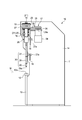
- FIG. 1 is a front view of the press machine 10.
- FIG. 2 is a partially broken right side view of the press machine 10.
- the press machine 10 of this embodiment is a press brake, and includes a main body frame 11, a table 13 that supports the lower mold 12, and a pair of side plates 14.
- the main body frame 11 forms an outline of the press machine 10.
- the lower mold 12 is a fixed (lower) mold, and is formed long in the left-right direction. As shown in FIG. 2, the lower mold 12 has a molding recess 12a.
- the table 13 is attached to the front side of the main body frame 11 and fixes the lower mold 12.
- the side plates 14 are respectively attached to the left and right side portions of the main body frame 11. Each of the side plates 14 is formed with guide plates 18 projecting inward at two locations, upper and lower.
- An upper cover plate 15 14 is attached between the pair of side plates 14.
- the press machine 10 includes a plurality of drive mechanisms 17.
- the plurality of drive mechanisms 17 are arranged side by side behind the upper cover plate 15 of the main body frame 11.
- Each of the drive mechanisms 17 is attached to the main body frame 11 by an attachment mechanism (not shown).
- the drive mechanism 17 includes a ball screw portion 21 having a screw shaft 19 and a nut 20, a first drive source 22, a first power transmission portion 23, a second drive source 24, a second power transmission portion 25, and a connecting portion. 26.
- the screw shaft 19 is an advancing / retreating part, is arranged in the vertical direction of the main body frame 11 and is rotatably supported by the main body frame 11.
- the length of the screw shaft 19 is set according to the movement range of the upper die 29.
- a ram 27 is attached below the screw shaft 19 via a connecting portion 26 having a function of preventing the screw shaft 19 from rotating.
- the connecting part 26 will be described later.
- the ram 27 is a plate-like member made of metal or the like, and has a weight of several tens to several hundreds kg, for example.
- the ram 27 is formed with a roller 27 a that sandwiches the guide plate 18. The roller 27a is guided by the guide plate 18 to guide the ram 27 in the vertical direction.
- a plurality of upper mold holders 28 are attached at regular intervals in the left-right direction.
- Each of the upper mold holders 28 has a clamp mechanism for sandwiching and holding the upper mold 29.
- the upper mold 29 is disposed so as to face the recess 12 a of the lower mold 12 when held by the upper mold holder 28.
- the upper die 29 has a tip portion 29 a that enters the recess 12 a of the lower die 12.
- the ram 27, the upper mold holder 28, and the upper mold 29 integrally form a structure 30 that moves in the vertical direction (see FIG. 2).
- the nut 20 is screwed to the screw shaft 19.
- the nut 20 is held in a rotatable state by a plurality of bearings (for example, ball bearings, roller bearings, etc.) of the bearing 16 formed on the main body frame 11.
- the nut 20 is in a state where movement in the vertical direction is restricted by the bearing 16. Accordingly, by rotating the screw shaft 19 in a state where the rotation of the nut 20 is restricted, the screw shaft 19 moves in the vertical direction, and by rotating the nut 20 in a state where the rotation of the screw shaft 19 is restricted. The screw shaft 19 can be moved in the vertical direction.
- the first drive source 22 is, for example, a servo motor. As the first drive source 22, a low torque and high speed rotation type servo motor is applied.
- the output shaft 22 a of the first drive source 22 is connected to the input side of the first power transmission unit 23.
- the first drive source 22 is supported by the main body frame 11 by a guide mechanism (not shown) so as to be movable in the vertical direction in accordance with the movement of the screw shaft 19.
- the first drive source 22 rotationally drives the output shaft 22a according to a command from a control device (not shown).
- the second drive source 24 is, for example, a servo motor. As the second drive source 24, a high torque and low speed rotation type servo motor is applied.
- the output shaft 24 a of the second drive source 24 is connected to the input side of the second power transmission unit 25.
- the second drive source 24 is fixed to the main body frame 11 by a fixing mechanism (not shown). Similar to the first drive source 22, the second drive source 24 rotationally drives the output shaft 24a according to a command from a control device (not shown).
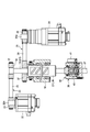
- FIG. 3 is a development view for explaining the drive mechanism 17 in the press machine 10.
- the first drive source 22 and the second drive source 24 are shown together.
- the first power transmission unit 23 includes a drive pulley 33, a driven pulley 34, and a belt 35.
- the drive pulley 33 is attached coaxially to the output shaft 22 a of the first drive source 22.
- the driven pulley 34 is coaxially attached to the upper end portion of the screw shaft 19.
- the belt 35 is stretched between the drive pulley 33 and the driven pulley 34. Therefore, by driving the first drive source 22, the screw shaft 19 is rotated at high speed and with low torque via the first power transmission unit 23. As a result, the screw shaft 19 moves at high speed in the vertical direction.
- the first drive source 22 is driven when the upper die 29 is approached or returned.
- the second power transmission unit 25 includes a drive pulley 36, a driven pulley 37, and a belt 38.
- the drive pulley 36 is coaxially attached to the output shaft 24 a of the second drive source 24.
- the driven pulley 37 is coaxially attached to the upper end portion of the nut 20.
- the belt 38 is stretched between the drive pulley 36 and the driven pulley 37. Accordingly, by driving the second drive source 24, the nut 20 is rotated at a low speed and with a high torque via the second power transmission unit 25. Due to the rotation of the nut 20, the screw shaft 19 is screwed at a low speed.
- the drive mechanism 17 is not limited to a configuration in which the first power transmission unit 23 and the second power transmission unit 25 include drive pulleys 33 and 36, driven pulleys 34 and 37, and belts 35 and 38.
- the driving force may be transmitted by a gear train.
- the two drive mechanisms 17 are not limited to being arranged with respect to one ram 27, and one or three or more drive mechanisms 17 may be arranged.
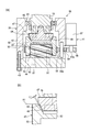
- FIG. 4A and 4B are diagrams for explaining the connecting portion 26 of the press machine 10, wherein FIG. 4A is a cross-sectional view showing a state at the time of approach (or at the time of return), and FIG. 4B is an enlarged cross-sectional view of the main part. .
- the connecting portion 26 includes a casing 39, a movable member 40, and a drive device 41.
- the casing 39 has a cylindrical portion 42, a bottom plate portion 43, and a sliding screw portion 44.
- the casing 39 connects the screw shaft 19 and the ram 27.
- the cylindrical portion 42 has an opening 45 at the upper end, and rotatably supports the lower end of the screw shaft 19 by a ball bearing 46 attached to the opening 45.
- a contact member 47 is attached to the lower end portion of the screw shaft 19 with a bolt or the like.
- the contact member 47 is formed in a truncated cone shape having a convex bottom surface, and an inclined surface 48 is formed around the contact member 47.
- the bottom plate portion 43 is fixed to the bottom portion of the cylindrical portion 42 with bolts 49.
- the bottom plate portion 43 is formed at the upper end portion of the ram 27 (see FIG. 3).
- the sliding screw portion 44 forms a sliding screw 50 on the outer periphery, and is fixed to the upper surface (inside the casing 39) of the bottom plate portion 43 by a bolt 51.
- the sliding screw portion 44 is separated from the contact member 47 of the screw shaft 19 and is disposed along the rotation axis of the screw shaft 19.
- a sliding screw nut 53 having a top plate 52 is used as the movable member 40.
- the sliding screw nut 53 is screwed to the sliding screw portion 44 described above.
- the top plate 52 is formed with an inclined surface 54 that can contact the inclined surface 48 of the contact member 47 of the screw shaft 19.
- a gear portion 55 is formed on the outer periphery of the sliding screw nut 53 over the entire circumference.
- the drive device 41 includes a drive source 57, a drive gear 58, and an intermediate gear 59.
- As the drive source 57 for example, a servo motor is used.
- a drive gear 58 is coaxially attached to the output shaft 57 a of the drive source 57.
- the intermediate gear 59 is rotatably supported by a shaft portion 59 a formed in the cylindrical portion 42 of the casing 39. Further, the intermediate gear 59 is disposed so as to mesh with the drive gear 58 and mesh with the gear portion 55 of the sliding screw nut 53.
- the drive device 41 rotates the output shaft 57a of the drive source 57 based on a command from a control device (not shown). As the drive gear 58 rotates, the slide screw nut 53 is rotated via the intermediate gear 59.
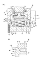
- FIG. 5A and 5B are diagrams for explaining the main part of the press machine 10, wherein FIG. 5A is a cross-sectional view showing a state during bending, and FIG. 5B is an enlarged cross-sectional view of the main part.
- FIG. 5A when the driving device 41 is driven to move the sliding screw nut 53 upward, the inclined surface 48 of the contact member 47 and the inclined surface 54 of the sliding screw nut 53 come into contact with each other. At this time, since the upward movement of the screw shaft 19 is restricted by the ball bearing 46, the sliding screw nut 53 can be strongly pressed against the contact member 47.
- the inclined surface 54 comes into strong contact with the inclined surface 48, and a frictional force that restricts the rotation of the contact member 47 (screw shaft 19) by the wedge effect can be generated.
- the inclination angle of the inclined surface 48 and the inclined surface 54 (inclination angle with respect to the rotation axis of the screw shaft 19) can be arbitrarily set.
- the screw portions of the slide screw 50 and the slide screw nut 53 are in a state where the inclined surfaces are in contact with each other.
- the sliding screw nut 53 receives a force in the axial direction (vertical direction)
- a frictional force is generated between the two by the wedge effect so that the sliding screw nut 53 does not rotate carelessly.
- the inclination angle of the thread portions of the slide screw portion 44 and the slide screw nut 53 can be arbitrarily set.
- the pitch of the slide screw 50 can be arbitrarily set.
- the gear train is used for transmission of the driving force in the driving device 41, it is not limited to this.
- a belt may be used to transmit the driving force, or a gear portion 55 on the outer periphery of the slide screw nut 53 may be used as a pinion gear, and the slide screw nut 53 may be rotated by linearly moving a rack engaged therewith.
- a drive source using hydraulic pressure or pneumatic pressure may be used.
- the surface configuration of the inclined surface 48 of the contact member 47 and the inclined surface 54 of the sliding screw nut is arbitrary. Both may be mirror finished, or one or both may be roughened to improve the frictional force. Such a contact surface is the same in the following second and third embodiments.
- the movable member 40 moves along the rotation axis of the screw shaft 19, but the present invention is not limited to this.
- the movable member 40 moves in parallel with being displaced from the rotation axis of the screw shaft 19.
- the movable member 40 may move in a direction inclined with respect to the rotation axis or in a direction perpendicular to the rotation axis.
- the moving direction of the movable member 40 is arbitrary as long as it eliminates rattling caused by the gap between the tip of the screw shaft 19 and the ram 27 and prevents the screw shaft 19 from rotating. Can be set.
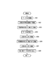
- step S01 a pressing method using the press machine 10 will be described with reference to FIG.
- the press machine 10 has a workpiece positioning mechanism (not shown), and the operator positions the workpiece W on the lower mold 12 by abutting the tip of the workpiece W against the positioning mechanism.
- step S02 the upper die 29 (ram 27) is lowered to a predetermined position.
- the screw shaft 19 is rotated at high speed via the first power transmission unit 23 by driving the first drive source 22.
- the movable member 40 of the connecting portion 26 is retracted to the position A ⁇ b> 1, and a gap L ⁇ b> 1 is generated between the contact member 47 and the slide screw nut 53. Yes.
- the screw shaft 19 can be freely rotated, and the ram 27 and the upper die 29 can be lowered to a predetermined position as the screw shaft 19 is lowered by high-speed rotation.
- the nut 20 may be rotated by driving the second drive source 24 in addition to the rotation of the screw shaft 19 by the first drive source 22.
- step S03 the drive device 41 of the connecting portion 26 is driven to rotate the slide screw nut 53, and as shown in FIG. 5B, the slide screw nut 53 is moved upward to the position A2, and the contact member 47 (screw It is made to contact
- the driving of the driving device 41 is stopped in a state where the inclined surface 54 of the sliding screw nut 53 is strongly pressed against the inclined surface 48 of the contact member 47.
- the screw shaft 19 is in a state in which the rotation is restricted by the sliding screw nut 53.
- the drive timing of the drive device 41 is not limited to the time after the screw shaft 19 is lowered to a predetermined position by the drive of the first drive source 22 (after step S02). In the middle of step S02, the driving device 41 may be driven.
- the second drive source 24 is driven and the nut 20 is rotated to lower the screw shaft 19 and move the upper die 29 to the bottom dead center.
- the workpiece W is sandwiched between the upper die 29 and the lower die 12, whereby the workpiece W is bent (step S04). Since the rotation of the screw shaft 19 is restricted by the sliding screw nut 53 as described above, the rotation is prevented even when the nut 20 is rotated. Further, at the time of bending, a force for pressing the inclined surface 54 against the inclined surface 48 is applied by a reaction force from the workpiece W, and the rotation of the screw shaft 19 is prevented.
- a control device controls the drive timing, drive amount, and the like of the first drive source 22, the second drive source 24, and the drive device 41 described above.
- the upper die 29 is retracted to the original position (see FIG. 2) by a procedure reverse to the above, and the workpiece W subjected to the bending process is taken out.
- the second drive source 24 is driven to reversely rotate the nut 20 and move the screw shaft 19 upward (step S05).
- the driving device 41 is driven to rotate the sliding screw nut 53 in the reverse direction to move it downward, and the sliding screw nut 53 is retracted from the contact member 47 (step S06).
- the screw shaft 19 is moved upward by driving the first drive source 22 and rotating the screw shaft 19 in the reverse direction (step S07).
- the retraction of the upper die 29 is not limited to this method.
- step S06 the driving device 41 is driven to retract the slide screw nut 53 from the contact member 47, and then the process proceeds to step S07.
- a method that does not use the second drive source 24 such as driving the first drive source 22 and rotating the screw shaft 19 to move upward may be used.
- the press machine 10 can easily and reliably prevent the screw shaft 19 from rotating by bringing the movable member 40 into contact with or retracting from the screw shaft 19. Furthermore, the position of the bottom dead center of the upper die 29 varies depending on whether the work W is bent by the load of the ram 27 or when the work W is bent by pressing the ram 27 downward with the screw shaft 19. Therefore, for example, even when the load required when bending the workpiece W is in the vicinity of the weight of the ram 27, the position of the bottom dead center of the upper mold 29 does not vary, and the workpiece W is scheduled. Can be reliably bent.
- the inclined surfaces 48 and 54 are used at the contact portion between the screw shaft 19 and the movable member 40, a strong frictional force can be generated by the wedge effect by strongly pressing the both, and the screw shaft 19 can be rotated. It can be prevented efficiently.
- the contact portion between the screw shaft 19 and the movable member 40 is not limited to the inclined surface, and for example, the flat portions may contact each other.
- the sliding screw nut 53 as the movable member 40, the inclined surface of the screw portion is strongly pressed, and the inadvertent rotation can be restricted by the wedge effect as described above.
- a nut with a normal screw thread may be used.
- a lock mechanism for preventing inadvertent rotation of the nut may be provided.
- the sliding screw nut 53 is moved in the same direction as the forward / backward direction of the screw shaft 19, the clearance generated between the screw shaft 19 and the ram 27 is surely eliminated by a simple operation such as rotating the sliding screw nut 53. can do.
- the gap between the screw shaft 19 and the ram 27 can be easily eliminated by the movable member 40, and the position of the bottom dead center of the upper die 29 is stabilized. Processing of W can be performed reliably, generation
- the lower portion of the screw shaft 19 is connected to the connecting portion 26, but the present invention is not limited to this.
- the screw shaft 19 may be rotatably held so as not to move in the vertical direction, and the lower portion of the nut 20 that is long in the vertical direction may be connected to the connecting portion 26.
- the nut 20 moves in the vertical direction along the screw shaft 19 by rotating the nut 20 or the screw shaft 19.
- a high-torque and low-speed rotation type servo motor is applied
- the second drive source 24 for rotating the nut 20 for example, low torque and A high-speed rotation type servo motor is applied.
- the nut 20 is rotatably held by the connecting portion 26, and the movable member 40 abuts or retreats with respect to the lower end of the nut 20.
- the point that the nut 20 may be connected to the connecting portion 26 instead of the screw shaft 19 is the same in other embodiments described below.
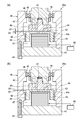
- FIGS. 7A and 7B are diagrams for explaining a main part of the press machine according to the second embodiment, wherein FIG. 7A is a cross-sectional view at the time of approach (or at the time of return), and FIG. 7B is a cross-sectional view at the time of bending. .
- FIG. 3 shows the connecting portion 26a, and the other configuration is the same as that of the first embodiment shown in FIGS.
- symbol is attached
- the connecting portion 26a uses a piezoelectric element 67 as a driving device for moving the movable member 40a.
- a contact member 60 is attached to the tip of the screw shaft 19 as in the first embodiment.
- the lower surface of the contact member 60 is a flat surface 61.
- the serration part 62 of an up-down direction is formed in an inner periphery.
- a cap-like member 63 is used for the movable member 40 a, and a flat surface 64 is formed on the upper surface thereof so as to face the flat surface 61 of the contact member 60.
- a serration portion 66 that is coupled to the serration portion 63 of the cylinder portion 42 is formed on the outer periphery of the cylinder portion 65 of the cap-shaped member 63. Therefore, the cap-shaped member 63 is restricted in rotation with respect to the cylindrical portion 42 of the casing 39 and can move in the vertical direction.
- cap-shaped member 63 and the casing 39 are not limited to being connected by the serration portions 63 and 66 described above. Any structure is applicable as long as the structure allows the movement in the vertical direction while restricting the rotation of the cap-shaped member 63. For example, a knurled structure or a spline structure may be applied.
- the piezoelectric element 67 is installed between the cap-shaped member 63 and the bottom plate portion 43.
- the piezoelectric element 67 is formed, for example, by stacking a large number of sheet-like piezoelectric elements, and a laminated type that utilizes displacement in the thickness direction when a voltage is applied.
- the number of stacked piezoelectric elements 67 is determined according to the amount of displacement of the cap-shaped member 63.
- the direction in which the piezoelectric element 67 is displaced is set to be the same as the direction of the rotation axis of the screw shaft 19.
- the piezoelectric element 67 is connected to the drive circuit 68.
- the drive circuit 68 is controlled by a control device (not shown) in the same manner as the various drive sources and drive devices described above.
- the piezoelectric element 67 when the piezoelectric element 67 is not driven (voltage is not applied), the flat portion 64 of the cap-like member 63 is positioned at B1, and the contact member 60 is flat. A gap L ⁇ b> 2 is formed between the portion 61. Therefore, during the approach of lowering the upper die 29 to a predetermined position, the screw shaft 19 is rotated at a high speed by driving the first drive source 22 without restricting the rotation of the screw shaft 19 (see FIG. 3). The upper die 29 is lowered at a high speed.
- the piezoelectric element 67 contracts and the cap-shaped member 63 returns to the original position B1 and returns to the state retracted from the contact member 60.
- the piezoelectric element 67 disposed between the casing 39 and the movable member 40 is used as the drive device for the movable member 40a, the movement of the movable member 40a is controlled by the drive circuit 68. Can be easily performed electrically. Further, by using the piezoelectric element 67, the movement of the movable member 40a can be controlled by a simple method such as application or stop of voltage.
- the pressing method according to the second embodiment is substantially the same as the pressing method shown in FIG.
- the flat portion 61 of the contact member 60 and the flat portion 64 of the cap-like member 63 are configured to contact each other, but the present invention is not limited to this.
- the inclined surfaces may be in contact with each other.
- One or both of the flat portions 61 and 64 may be mirrored or roughened.
- the drive circuit 68 may be formed in the casing 39, and may be formed in the main body frame 11 of the press machine 10 via a wire or radio
- FIGS. 8A and 8B are diagrams for explaining a main part of the press machine according to the third embodiment, in which FIG. 8A is a sectional view at the time of approach, and FIG. 8B is an enlarged view around an inclined surface.
- FIGS. 9A and 9B are diagrams for explaining a main part of the press machine, in which FIG. 9A is a cross-sectional view during bending, and FIG. 9B is an enlarged view around an inclined surface.
- FIG.8 and FIG.9 it has shown about the connection part 26b, About another structure, it is the same as that of 1st Embodiment shown in FIG.1 and FIG.2.
- the same components as those in the above-described embodiment are denoted by the same reference numerals, and the description thereof is omitted or simplified.
- the positions of the contact member 47 and the slide screw portion 44 are opposite to the connecting portion 26 of the first embodiment.
- the sliding screw portion 44 is fixed to the lower end portion of the screw shaft 19 with, for example, a bolt.
- the screw shaft 19 is supported by the ball bearing 46 so as to be rotatable with respect to the casing 39 and is regulated so as not to move in the vertical direction with respect to the casing 39 in the same manner as in the first embodiment.
- the contact member 47 is fixed to the bottom plate portion 43 of the casing 39 by, for example, a bolt.
- a sliding screw nut 53 is attached to the sliding screw portion 44 as a movable member 40b by screw coupling. Thereby, the inclined surface 54 of the sliding screw nut 53 is disposed to face the inclined surface 48 of the contact member 47. Further, the sliding screw nut 53 moves in the vertical direction with respect to the casing 39 by rotating. As shown in FIG. 8A, the gear portion 55 formed on the outer periphery of the slide screw nut 53 is formed in accordance with the position of the intermediate gear 59 of the drive device 41. The gear portion 55 may be formed longer in the vertical direction than the first embodiment so as to correspond to the vertical movement of the sliding screw nut 53.
- This connecting portion 26b is the same as in the first embodiment in that the sliding screw nut 53 is rotated by driving the drive device 41, and the inclined surface 54 is brought into contact with or retracted from the inclined surface 48 of the contact member 47. . As shown in FIG. 8, when the lower end of the slide screw nut 53 is at the position C1, a gap L3 is formed between the inclined surfaces 48 and 54, and the first drive source 22 is driven (FIG. 3). The screw shaft 19 can be rotated at a high speed.
- the driving device 41 may be driven to rotate the sliding screw nut 53 in the same direction in synchronization with the rotation of the screw shaft 19.
- the sliding screw portion 44 also rotates.
- the drive of the drive device 41 is controlled by a control device (not shown) so as to be synchronized with the drive of the first drive source 22.
- the inclined surface 54 is brought into contact with the inclined surface 48 of the contact member 47 by driving the driving device 41 to rotate the slide screw nut 53 and moving it downward to the position C2.
- the sliding screw nut 53 is held by the contact member 47 by the wedge effect, and the rotation is restricted.
- the screw portions of the slide screw nut 53 and the slide screw portion 44 are also strongly pressed in the same manner, the rotation of the slide screw portion 44 is restricted by the wedge effect. Thereby, the screw shaft 19 is in a state in which the rotation is restricted.
- the rotation of the screw shaft 19 is reliably prevented by moving the movable member 40a, and the clearance between the screw shaft 19 and the ram 27 is reliably prevented. Therefore, the position of the bottom dead center of the upper mold 29 can be prevented from changing.
- the pressing method according to the third embodiment is substantially the same as the pressing method shown in FIG.
- the contact members 47 and 60 are attached to the tip of the screw shaft 19, but the present invention is not limited to this, and the contact members 47 and 60 are not attached. May be. In this case, the movable members 40, 40 a come into contact with the tip portion of the screw shaft 19 to eliminate the gap, and the rotation of the screw shaft 19 is prevented.
- the press machine 10 in which the structural body 30 including the upper mold 29 and the ram 27 and the upper mold holder 28 moves in the vertical direction is shown, but the present invention is not limited to this.
- the lower mold 12 may move in the vertical direction like the upper mold 29, or the lower mold 12 may move in the vertical direction with the upper mold 29 fixed.
- the table 13 and the like holding the lower mold 12 including the lower mold 12 are constituent bodies, and this constituent body is moved in the vertical direction by the drive mechanism 17. Further, the connecting portion 26 and the like described above are formed between the drive mechanism 17 and the table 13. Therefore, the point that the rotation of the screw shaft 19 is prevented or the rotation is permitted by driving the driving device 41 to move the movable member 40 and the like is the same as in the above embodiments.
Landscapes
- Engineering & Computer Science (AREA)
- Mechanical Engineering (AREA)
- General Engineering & Computer Science (AREA)
- Press Drives And Press Lines (AREA)
- Transmission Devices (AREA)
- Bending Of Plates, Rods, And Pipes (AREA)
Abstract
Description
次に、第2駆動源または第1駆動源によりナットまたはネジ軸を回転させることによりワークを加工することを特徴とする。
第1実施形態に係るプレス機械について、図1~図5を参照しながら説明する。図1は、プレス機械10の正面図である。図2は、プレス機械10の一部破断右側面図である。図1及び図2に示すように、本実施形態のプレス機械10は、プレスブレーキであって、本体フレーム11と、下型12を支持するテーブル13と、一対の側板14と、を備える。本体フレーム11は、プレス機械10の外郭を形成する。
第2実施形態について図7を参照しながら説明する。図7は、第2実施形態に係るプレス機械の要部を説明する図であって、(a)はアプローチ時(またはリターン時)の断面図、(b)は曲げ加工時の断面図である。また、図3では、連結部26aについて示しており、他の構成については図1及び図2に示す第1実施形態と同様である。また、本実施形態において、第1実施形態と同様の構成については、同じ符号を付してその説明を省略または簡略化する。
第3実施形態について図8及び図9を参照しながら説明する。図8は、第3実施形態に係るプレス機械の要部を説明する図であって、(a)はアプローチ時の断面図、(b)は傾斜面周りの拡大図である。図9は、プレス機械の要部を説明する図であって、(a)は曲げ加工時の断面図、(b)は傾斜面周りの拡大図である。また、図8及び図9では、連結部26bについて示しており、他の構成については図1及び図2に示す第1実施形態と同様である。なお、本実施形態において、前述の実施形態と同様の構成については、同じ符号を付してその説明を省略または簡略化する。
10・・・プレス機械
12・・・下型
17・・・駆動機構
19・・・ネジ軸
20・・・ナット
22・・・第1駆動源
24・・・第2駆動源
26、26a、26b・・・連結部
27・・・ラム
28・・・上型ホルダー
29・・・上型
30・・・構成体 39・・・ケーシング
40、40a、40b・・・可動部材
41・・・駆動装置
44・・・すべりネジ部
48、54・・・傾斜面
53・・・すべりネジナット
67・・・圧電素子
Claims (7)
- 上型及び下型の少なくとも一方を移動させる駆動機構を備え、前記上型と前記下型との間に配置されたワークを加工するプレス機械において、
前記駆動機構は、ネジ軸または前記ネジ軸と結合するナットを進退部品として用い、前記ネジ軸を回転させる第1駆動源と、前記ナットを回転させる第2駆動源と、を有し、
前記上型または前記下型を含む構成体は、前記ネジ軸または前記ナットを回転可能に支持するケーシングと、前記ケーシング内に移動可能に形成されかつ前記ネジ軸または前記ナットの先端部分に対して当接または退避可能な可動部材と、前記可動部材を移動させる駆動装置と、を備えることを特徴とするプレス機械。 - 前記ネジ軸または前記ナットの先端部分は、進退方向に対して傾斜する傾斜面を備え、
前記可動部材は、前記傾斜面と当接可能な傾斜面を備えることを特徴とする請求項1記載のプレス機械。 - 前記可動部材は、前記ケーシングに形成されたすべりネジと結合するすべりネジナットが用いられ、
前記すべりネジナットは、前記駆動装置によって回転することにより前記ネジ軸または前記ナットの先端部分に対して当接または退避することを特徴とする請求項1または請求項2記載のプレス機械。 - 前記すべりネジは、前記ネジ軸の軸心に沿って前記ケーシングに形成され、
前記すべりネジナットは、回転により前記ネジ軸または前記ナットの進退方向と同一方向に移動することを特徴とする請求項3記載のプレス機械。 - 前記駆動装置としては、前記ケーシングと前記可動部材との間に配置された圧電素子が用いられ、
前記可動部材は、前記圧電素子の伸縮により前記ネジ軸または前記ナットの先端部分に対して当接または退避する請求項1または請求項2記載のプレス機械。 - 前記上型を含む構成体は、前記上型を保持する上型ホルダーと、前記上型ホルダーが取り付けられるラムと、を含み、
前記ケーシングは、前記ラムの上部に形成されて前記ネジ軸または前記ナットと前記ラムとを接続することを特徴とする請求項1~請求項5のいずれか1項に記載のプレス機械。 - 上型及び下型の少なくとも一方を移動させる駆動機構を備え、前記上型と前記下型との間に配置されたワークを加工するプレス方法において、
前記駆動機構は、ネジ軸または前記前記ネジ軸と結合するナットを進退部品として用い、前記ネジ軸を回転させる第1駆動源と、前記ナットを回転させる第2駆動源と、を有し、
前記上型または前記下型を含む構成体は、前記ネジ軸または前記ナットを回転可能に支持するケーシングと、前記ケーシング内に移動可能に形成されかつ前記ネジ軸または前記ナットの先端部分に対して当接または退避可能な可動部材と、前記可動部材を移動させる駆動装置と、を備え、
前記可動部材を前記ネジ軸または前記ナットの先端部分から退避させた状態で前記第1駆動源または前記第2駆動源により前記ネジ軸または前記ナットを回転させ、前記上型及び前記下型の少なくとも一方を移動させ、
次に、前記駆動装置によって前記可動部材を前記ネジ軸または前記ナットの先端部分に当接させ、
次に、前記第2駆動源または前記第1駆動源により前記ナットまたは前記ネジ軸を回転させることにより前記ワークを加工することを特徴とするプレス方法。
Priority Applications (4)
| Application Number | Priority Date | Filing Date | Title |
|---|---|---|---|
| KR1020167008275A KR101769076B1 (ko) | 2013-10-02 | 2014-08-20 | 프레스 기계 및 프레스 방법 |
| US15/025,847 US10279556B2 (en) | 2013-10-02 | 2014-08-20 | Press machine and press method |
| CN201480053757.5A CN105593009B (zh) | 2013-10-02 | 2014-08-20 | 冲压机械以及冲压方法 |
| JP2015540421A JP6065123B2 (ja) | 2013-10-02 | 2014-08-20 | プレス機械及びプレス方法 |
Applications Claiming Priority (2)
| Application Number | Priority Date | Filing Date | Title |
|---|---|---|---|
| JP2013207057 | 2013-10-02 | ||
| JP2013-207057 | 2013-10-02 |
Publications (1)
| Publication Number | Publication Date |
|---|---|
| WO2015049930A1 true WO2015049930A1 (ja) | 2015-04-09 |
Family
ID=52778526
Family Applications (1)
| Application Number | Title | Priority Date | Filing Date |
|---|---|---|---|
| PCT/JP2014/071790 Ceased WO2015049930A1 (ja) | 2013-10-02 | 2014-08-20 | プレス機械及びプレス方法 |
Country Status (5)
| Country | Link |
|---|---|
| US (1) | US10279556B2 (ja) |
| JP (1) | JP6065123B2 (ja) |
| KR (1) | KR101769076B1 (ja) |
| CN (1) | CN105593009B (ja) |
| WO (1) | WO2015049930A1 (ja) |
Cited By (8)
| Publication number | Priority date | Publication date | Assignee | Title |
|---|---|---|---|---|
| USD802639S1 (en) * | 2016-03-03 | 2017-11-14 | Sintokogio, Ltd. | Electric cylinder |
| JP2017202490A (ja) * | 2016-05-09 | 2017-11-16 | 株式会社アマダホールディングス | プレス機械 |
| JP2017205798A (ja) * | 2016-05-20 | 2017-11-24 | 株式会社アマダホールディングス | プレス機械 |
| USD804553S1 (en) * | 2016-04-05 | 2017-12-05 | Sintokogio, Ltd. | Electric cylinder |
| WO2018079175A1 (ja) * | 2016-10-27 | 2018-05-03 | 村田機械株式会社 | プレスブレーキ |
| JP7584598B1 (ja) | 2023-09-06 | 2024-11-15 | 株式会社アマダ | 曲げ加工機 |
| WO2025053237A1 (ja) * | 2023-09-06 | 2025-03-13 | 株式会社アマダ | 曲げ加工機 |
| JP7713568B1 (ja) * | 2024-08-05 | 2025-07-25 | 株式会社アマダ | 曲げ加工機 |
Families Citing this family (8)
| Publication number | Priority date | Publication date | Assignee | Title |
|---|---|---|---|---|
| JP6768499B2 (ja) | 2016-12-28 | 2020-10-14 | コマツ産機株式会社 | プレス装置およびプレス装置の制御方法 |
| CN106696328A (zh) * | 2017-01-16 | 2017-05-24 | 爱克(苏州)机械有限公司 | 一种双伺服数控转塔冲床的主传动 |
| TR201705931A2 (tr) * | 2017-04-21 | 2017-09-21 | Durmazlar Makina Sanayi Ve Ticaret Anonim Sirketi | Tek gövdeli̇ tandem pres |
| CN111156303B (zh) * | 2020-02-25 | 2021-07-06 | 常州工学院 | 一种同轴复合式双螺旋压力装置 |
| JP7474218B2 (ja) * | 2021-03-24 | 2024-04-24 | アイダエンジニアリング株式会社 | プレス機械及びプレス機械の動作設定方法 |
| US12214567B2 (en) | 2021-09-08 | 2025-02-04 | PDInnovative LLC | Press machine having planetary gear system for multi-speed drive functionality |
| US11919267B2 (en) * | 2021-09-21 | 2024-03-05 | PDInnovative LLC | Linear-actuated press machine having telescopic drive configuration for multi-speed drive functionality |
| US11819906B2 (en) | 2021-09-21 | 2023-11-21 | PDInnovative LLC | Linear-actuated press machine having multiple motors and clutch system for multi-speed drive functionality |
Citations (4)
| Publication number | Priority date | Publication date | Assignee | Title |
|---|---|---|---|---|
| DE839150C (de) * | 1950-07-15 | 1952-05-15 | Otto Georg Dr Ing | Elektrisch betriebene Spindelpresse |
| DE754614C (de) * | 1943-12-03 | 1952-10-27 | Schloemann Ag | Gegenschlaghammer |
| JP2004188460A (ja) * | 2002-12-11 | 2004-07-08 | Toyo Koki:Kk | 往復駆動機構およびその機構を用いたプレス機械 |
| WO2013105547A1 (ja) * | 2012-01-10 | 2013-07-18 | 株式会社 アマダ | プレス機械 |
Family Cites Families (5)
| Publication number | Priority date | Publication date | Assignee | Title |
|---|---|---|---|---|
| WO1993020996A1 (en) * | 1992-04-13 | 1993-10-28 | Apic Yamada Corporation | Method of transfer mold and apparatus for transfer mold |
| TWI293599B (en) * | 2001-11-30 | 2008-02-21 | Apic Yamada Corp | Compression molding machine |
| JP2008018444A (ja) * | 2006-07-12 | 2008-01-31 | Amada Co Ltd | 加圧装置およびワークの角部成形装置 |
| JP5593992B2 (ja) * | 2010-09-09 | 2014-09-24 | 村田機械株式会社 | プレス機械 |
| JP5531878B2 (ja) * | 2010-09-15 | 2014-06-25 | 村田機械株式会社 | プレス機械 |
-
2014
- 2014-08-20 US US15/025,847 patent/US10279556B2/en active Active
- 2014-08-20 WO PCT/JP2014/071790 patent/WO2015049930A1/ja not_active Ceased
- 2014-08-20 CN CN201480053757.5A patent/CN105593009B/zh active Active
- 2014-08-20 KR KR1020167008275A patent/KR101769076B1/ko active Active
- 2014-08-20 JP JP2015540421A patent/JP6065123B2/ja active Active
Patent Citations (4)
| Publication number | Priority date | Publication date | Assignee | Title |
|---|---|---|---|---|
| DE754614C (de) * | 1943-12-03 | 1952-10-27 | Schloemann Ag | Gegenschlaghammer |
| DE839150C (de) * | 1950-07-15 | 1952-05-15 | Otto Georg Dr Ing | Elektrisch betriebene Spindelpresse |
| JP2004188460A (ja) * | 2002-12-11 | 2004-07-08 | Toyo Koki:Kk | 往復駆動機構およびその機構を用いたプレス機械 |
| WO2013105547A1 (ja) * | 2012-01-10 | 2013-07-18 | 株式会社 アマダ | プレス機械 |
Cited By (13)
| Publication number | Priority date | Publication date | Assignee | Title |
|---|---|---|---|---|
| USD802639S1 (en) * | 2016-03-03 | 2017-11-14 | Sintokogio, Ltd. | Electric cylinder |
| USD804553S1 (en) * | 2016-04-05 | 2017-12-05 | Sintokogio, Ltd. | Electric cylinder |
| JP2017202490A (ja) * | 2016-05-09 | 2017-11-16 | 株式会社アマダホールディングス | プレス機械 |
| JP2017205798A (ja) * | 2016-05-20 | 2017-11-24 | 株式会社アマダホールディングス | プレス機械 |
| JPWO2018079175A1 (ja) * | 2016-10-27 | 2019-09-12 | 村田機械株式会社 | プレスブレーキ |
| CN109843462A (zh) * | 2016-10-27 | 2019-06-04 | 村田机械株式会社 | 弯板机 |
| WO2018079175A1 (ja) * | 2016-10-27 | 2018-05-03 | 村田機械株式会社 | プレスブレーキ |
| US10919248B2 (en) | 2016-10-27 | 2021-02-16 | Murata Machinery, Ltd. | Press brake |
| JP7584598B1 (ja) | 2023-09-06 | 2024-11-15 | 株式会社アマダ | 曲げ加工機 |
| WO2025053237A1 (ja) * | 2023-09-06 | 2025-03-13 | 株式会社アマダ | 曲げ加工機 |
| WO2025053238A1 (ja) * | 2023-09-06 | 2025-03-13 | 株式会社アマダ | 曲げ加工機 |
| JP2025037360A (ja) * | 2023-09-06 | 2025-03-18 | 株式会社アマダ | 曲げ加工機 |
| JP7713568B1 (ja) * | 2024-08-05 | 2025-07-25 | 株式会社アマダ | 曲げ加工機 |
Also Published As
| Publication number | Publication date |
|---|---|
| JPWO2015049930A1 (ja) | 2017-03-09 |
| KR20160047568A (ko) | 2016-05-02 |
| JP6065123B2 (ja) | 2017-01-25 |
| US10279556B2 (en) | 2019-05-07 |
| KR101769076B1 (ko) | 2017-08-17 |
| US20160243778A1 (en) | 2016-08-25 |
| CN105593009B (zh) | 2017-06-13 |
| CN105593009A (zh) | 2016-05-18 |
Similar Documents
| Publication | Publication Date | Title |
|---|---|---|
| JP6065123B2 (ja) | プレス機械及びプレス方法 | |
| JP4373399B2 (ja) | プレス装置 | |
| JP4351215B2 (ja) | プレス装置 | |
| JP6662467B2 (ja) | プレスブレーキ | |
| JP6016896B2 (ja) | ワーク、特に金属薄板を加工するプレスの形態の工作機械 | |
| US5488880A (en) | Two-speed linear actuator driven by two motors | |
| CN101648240A (zh) | 一种板材加工的冲压机床 | |
| JP2012076183A (ja) | 工作機械におけるワーククランプ装置 | |
| KR101411220B1 (ko) | 마찰 용접기 | |
| WO2014103561A1 (ja) | レーザ加工機の面押しツールおよびその面押し方法 | |
| JP2015196195A (ja) | 被加工材を加工するプレス装置 | |
| CN203830500U (zh) | 多联冲压平台 | |
| CN104493945B (zh) | 板材加工装置及其工作方法 | |
| EP3736061B1 (en) | Fine blanking system and method for operating the same | |
| JP2009006344A (ja) | ヘミング加工装置,ヘミング加工方法およびヘミング加工装置におけるスライド部の隙間調整方法 | |
| EP2995446B1 (en) | Press and process for deforming metal pieces | |
| JP6086481B2 (ja) | ヘミング加工装置 | |
| KR101346464B1 (ko) | 고속 고효율 엔씨 인덱스 테이블 | |
| JP4933084B2 (ja) | プレス装置 | |
| CN201482861U (zh) | 一种板材加工的冲压机床 | |
| CN110944779B (zh) | 转塔刀架 | |
| JP6086432B2 (ja) | プレス加工装置及びプレス加工方法 | |
| JP6481362B2 (ja) | 歯車成型用金型装置 | |
| JP2008272898A (ja) | 工作機械における工具のアンクランプ方法 | |
| JP5580656B2 (ja) | プレス機械のフィード装置およびそれを用いたフィード装置付きプレス機械 |
Legal Events
| Date | Code | Title | Description |
|---|---|---|---|
| 121 | Ep: the epo has been informed by wipo that ep was designated in this application |
Ref document number: 14850172 Country of ref document: EP Kind code of ref document: A1 |
|
| ENP | Entry into the national phase |
Ref document number: 2015540421 Country of ref document: JP Kind code of ref document: A |
|
| ENP | Entry into the national phase |
Ref document number: 20167008275 Country of ref document: KR Kind code of ref document: A |
|
| WWE | Wipo information: entry into national phase |
Ref document number: 15025847 Country of ref document: US |
|
| NENP | Non-entry into the national phase |
Ref country code: DE |
|
| 122 | Ep: pct application non-entry in european phase |
Ref document number: 14850172 Country of ref document: EP Kind code of ref document: A1 |