WO2015046238A1 - 連続鋳造方法 - Google Patents
連続鋳造方法 Download PDFInfo
- Publication number
- WO2015046238A1 WO2015046238A1 PCT/JP2014/075268 JP2014075268W WO2015046238A1 WO 2015046238 A1 WO2015046238 A1 WO 2015046238A1 JP 2014075268 W JP2014075268 W JP 2014075268W WO 2015046238 A1 WO2015046238 A1 WO 2015046238A1
- Authority
- WO
- WIPO (PCT)
- Prior art keywords
- stainless steel
- tundish
- molten
- molten stainless
- molten metal
- Prior art date
- Legal status (The legal status is an assumption and is not a legal conclusion. Google has not performed a legal analysis and makes no representation as to the accuracy of the status listed.)
- Ceased
Links
Images


Classifications
-
- B—PERFORMING OPERATIONS; TRANSPORTING
- B22—CASTING; POWDER METALLURGY
- B22D—CASTING OF METALS; CASTING OF OTHER SUBSTANCES BY THE SAME PROCESSES OR DEVICES
- B22D11/00—Continuous casting of metals, i.e. casting in indefinite lengths
- B22D11/001—Continuous casting of metals, i.e. casting in indefinite lengths of specific alloys
- B22D11/002—Stainless steels
-
- B—PERFORMING OPERATIONS; TRANSPORTING
- B22—CASTING; POWDER METALLURGY
- B22D—CASTING OF METALS; CASTING OF OTHER SUBSTANCES BY THE SAME PROCESSES OR DEVICES
- B22D11/00—Continuous casting of metals, i.e. casting in indefinite lengths
-
- B—PERFORMING OPERATIONS; TRANSPORTING
- B22—CASTING; POWDER METALLURGY
- B22D—CASTING OF METALS; CASTING OF OTHER SUBSTANCES BY THE SAME PROCESSES OR DEVICES
- B22D11/00—Continuous casting of metals, i.e. casting in indefinite lengths
- B22D11/04—Continuous casting of metals, i.e. casting in indefinite lengths into open-ended moulds
- B22D11/041—Continuous casting of metals, i.e. casting in indefinite lengths into open-ended moulds for vertical casting
-
- B—PERFORMING OPERATIONS; TRANSPORTING
- B22—CASTING; POWDER METALLURGY
- B22D—CASTING OF METALS; CASTING OF OTHER SUBSTANCES BY THE SAME PROCESSES OR DEVICES
- B22D11/00—Continuous casting of metals, i.e. casting in indefinite lengths
- B22D11/10—Supplying or treating molten metal
-
- B—PERFORMING OPERATIONS; TRANSPORTING
- B22—CASTING; POWDER METALLURGY
- B22D—CASTING OF METALS; CASTING OF OTHER SUBSTANCES BY THE SAME PROCESSES OR DEVICES
- B22D11/00—Continuous casting of metals, i.e. casting in indefinite lengths
- B22D11/10—Supplying or treating molten metal
- B22D11/106—Shielding the molten jet
-
- B—PERFORMING OPERATIONS; TRANSPORTING
- B22—CASTING; POWDER METALLURGY
- B22D—CASTING OF METALS; CASTING OF OTHER SUBSTANCES BY THE SAME PROCESSES OR DEVICES
- B22D11/00—Continuous casting of metals, i.e. casting in indefinite lengths
- B22D11/10—Supplying or treating molten metal
- B22D11/108—Feeding additives, powders, or the like
-
- B—PERFORMING OPERATIONS; TRANSPORTING
- B22—CASTING; POWDER METALLURGY
- B22D—CASTING OF METALS; CASTING OF OTHER SUBSTANCES BY THE SAME PROCESSES OR DEVICES
- B22D11/00—Continuous casting of metals, i.e. casting in indefinite lengths
- B22D11/10—Supplying or treating molten metal
- B22D11/11—Treating the molten metal
- B22D11/111—Treating the molten metal by using protecting powders
-
- B—PERFORMING OPERATIONS; TRANSPORTING
- B22—CASTING; POWDER METALLURGY
- B22D—CASTING OF METALS; CASTING OF OTHER SUBSTANCES BY THE SAME PROCESSES OR DEVICES
- B22D11/00—Continuous casting of metals, i.e. casting in indefinite lengths
- B22D11/10—Supplying or treating molten metal
- B22D11/11—Treating the molten metal
- B22D11/116—Refining the metal
- B22D11/117—Refining the metal by treating with gases
-
- B—PERFORMING OPERATIONS; TRANSPORTING
- B22—CASTING; POWDER METALLURGY
- B22D—CASTING OF METALS; CASTING OF OTHER SUBSTANCES BY THE SAME PROCESSES OR DEVICES
- B22D11/00—Continuous casting of metals, i.e. casting in indefinite lengths
- B22D11/16—Controlling or regulating processes or operations
Definitions
- This invention relates to a continuous casting method.
- molten iron is produced by melting raw materials in an electric furnace, and the produced molten iron removes carbon that deteriorates the properties of stainless steel in a converter and a vacuum degassing device. Refining including decarburization is performed to form molten steel, and then the molten steel is continuously cast to solidify to form a plate-like slab or the like. In the refining process, the final components of the molten steel are adjusted.
- Patent Document 1 describes a method for producing a continuous casting (continuous casting) slab using argon gas as a seal gas.
- the sealing gas As in the manufacturing method of Patent Document 1, the argon gas taken into the molten steel remains as bubbles, and bubble defects due to argon gas on the surface of the continuous casting slab and in the vicinity thereof, that is, the surface Defects are likely to occur. And when a surface defect arises in a continuous casting slab, in order to ensure required quality, it is necessary to scrape the surface and there exists a problem that cost increases. For this reason, the present inventor uses nitrogen that does not easily remain as bubbles in the molten steel as an inert gas, and further forms a powder layer on the surface of the molten steel in order to prevent the penetration of nitrogen into the molten steel. Developed technology to shut off steel and molten steel.
- stainless steel includes steel types that contain easily oxidizable titanium or the like as a component.
- aluminum that is more reactive with oxygen is added to remove oxygen in the molten steel. Acid is done.
- Aluminum reacts with oxygen to become alumina, thereby removing oxygen in the molten steel.
- the melting point of alumina is as high as 2020 ° C.
- the alumina in the molten steel is precipitated in the casting process in which the temperature of the molten steel is lowered, and may adhere and deposit on the inner wall of the nozzle from the tundish to the mold, for example. is there.
- the present inventor has taken measures to prevent nozzle clogging by adding a Ca-containing material to molten steel in a tundish to change alumina to a calcium aluminate having a lower melting point.
- An object of the present invention is to provide a continuous casting method for reducing surface defects in a slab (metal piece) obtained by casting a metal.
- the continuous casting method according to the present invention injects molten metal, which has been deoxidized in a ladle, into a tundish, and continuously injects the molten metal in the tundish into a mold.
- a long nozzle installation step in which a long nozzle extending in the tundish is provided in the pan as an injection nozzle for injecting molten metal in the ladle into the tundish, and a long A casting step in which the molten metal is injected into the tundish through the long nozzle while the nozzle outlet is immersed in the molten metal injected into the tundish, and the molten metal in the tundish is injected into the mold, and the tundish A spraying step of spraying tundish powder so as to cover the surface of the molten metal inside, and a tundish pow Including a sealing gas supply step of supplying nitrogen gas as a sealing gas around the molten metal sprayed with, and an addition step of adding a calcium-containing material to the molten metal in a state other than the state stored in the tundish .
- the surface defect in the metal piece cast from the molten metal is prevented while preventing the nozzle from clogging from the tundish to the mold at the time of casting the molten metal subjected to aluminum deoxidation. It becomes possible to reduce.
- FIG. 6 is a diagram comparing the deposition state of precipitates with a tundish immersion nozzle during continuous casting in Examples 1 to 5.
- Embodiment 1 FIG.
- a continuous casting method according to Embodiment 1 of the present invention will be described with reference to the accompanying drawings.
- a continuous casting method of stainless steel containing titanium (Ti) which is one of stainless steels that require aluminum deoxidation in the secondary refining process, will be described.
- stainless steel is manufactured by performing a melting process, a primary refining process, a secondary refining process, and a casting process in this order.
- the melting step scraps and alloys as raw materials for stainless steel are melted in an electric furnace to generate hot metal, and the generated hot metal is poured into a converter.
- a rough decarburization process is performed to remove carbon contained by blowing oxygen into the molten iron in the converter, thereby producing a molten stainless steel and slag containing oxides and impurities. Generate.
- the components of the molten stainless steel are analyzed, and the rough adjustment of the components to which the alloy is added is performed in order to approximate the target components.
- the molten stainless steel produced in the primary refining process is delivered to the ladle and transferred to the secondary refining process.
- the molten stainless steel 1 is put together with a ladle 2 in a vacuum oxygen decarburization apparatus (also referred to as VOD, hereinafter referred to as VOD) 10 for finishing.
- VOD vacuum oxygen decarburization apparatus
- Decarburization treatment, final desulfurization, degassing treatment of oxygen, nitrogen, hydrogen, etc., and removal of inclusions are performed.
- the molten stainless steel 1 receives the above-mentioned process, the molten stainless steel which has the target characteristic as a product produces
- the components of the molten stainless steel 1 are analyzed, and final adjustment of the components is also performed, in which an alloy is introduced to bring the components closer to the target components.
- the molten stainless steel 1 constitutes a molten metal.
- the VOD 10 has a vacuum chamber 11 in which the ladle 2 can be placed.
- the ladle 2 is filled with the molten stainless steel 1 after the slag containing impurities such as oxides is removed in the primary refining process.
- the vacuum chamber 11 has an exhaust pipe 11a for exhausting internal air to the outside, and the exhaust pipe 11a is configured to be connected to a vacuum pump and a steam ejector (not shown).
- the VOD 10 has an oxygen gas lance 12 that extends from the outside of the vacuum chamber 11 to the inside and is configured to blow oxygen from the upper portion of the ladle 2 to the molten stainless steel 1 in the vacuum chamber 11.
- the contained carbon is removed by reacting with blown oxygen and being oxidized to carbon monoxide. And the said reaction of contained carbon is accelerated
- the VOD 10 is used for supplying an alloy to the molten stainless steel 1 in the ladle 2 from above and an argon gas lance 13 for sending argon (Ar) gas for stirring to the molten stainless steel 1 from the bottom of the ladle 2.
- An alloy hopper 14 is provided in the vacuum chamber 11. Ti, which easily reacts with oxygen, is added to the molten stainless steel 1 in the vacuum chamber 11 as a component. For this reason, in order to remove the unreacted oxygen contained in the molten stainless steel 1 before adding Ti, aluminum (Al) having a higher reactivity with oxygen than Ti is used as a deoxidizing agent (deoxygenating agent). ) Containing alloy is added from the alloy hopper 14.
- Al in the Al-containing alloy reacts with oxygen to become alumina (Al 2 O 3 ), and most of Al 2 O 3 is aggregated and absorbed in the slag by stirring with Ar gas. Note that nitrogen and hydrogen contained in the molten stainless steel 1 are removed from the molten stainless steel 1 by reducing the pressure in the vacuum chamber 11.
- the ladle 2 is removed from the vacuum chamber 11 and set in the continuous casting apparatus (CC) 100.
- the molten stainless steel 1 in the ladle 2 is poured into a continuous casting apparatus 100 and further cast into a slab-like stainless steel piece 1c as a metal piece, for example, by a mold 105 provided in the continuous casting apparatus 100.
- the cast stainless steel piece 1c is hot-rolled or cold-rolled into a hot-rolled steel strip or a cold-rolled steel strip in the following rolling process (not shown).
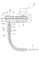
- the continuous casting apparatus 100 has a tundish 101 that is a container for sending the molten stainless steel 1 sent from the ladle 2 to the mold 105 while temporarily storing the molten stainless steel 1.
- the tundish 101 has a main body 101b whose upper part is open, an upper lid 101c that closes the upper part of the main body 101b and blocks it from the outside, and an immersion nozzle 101d that extends from the bottom of the main body 101b.
- the interior space 101a closed by these inside with the main body 101b and the upper cover 101c is formed.
- the immersion nozzle 101d opens into the internal space 101a from the bottom of the main body 101b at the inlet 101e.
- the ladle 2 is set above the tundish 101, and a long nozzle 3 as an injection nozzle that extends through the upper lid 101c and extends into the internal space 101a is connected to the bottom of the ladle 2.
- a spout 3a at the lower end of the long nozzle 3 opens in the internal space 101a.
- the long nozzle 3 and the upper lid 101c are sealed to maintain airtightness.
- a plurality of gas supply nozzles 102 are provided on the upper lid 101c.
- the gas supply nozzle 102 is connected to a gas supply source (not shown), and sends a predetermined gas into the internal space 101a from the top to the bottom.
- the long nozzle 3 is configured so that the predetermined gas is supplied into the long nozzle 3.
- the upper lid 101c is provided with a powder nozzle 103 for sending tundish powder (hereinafter referred to as TD powder) 5 from the upper side to the lower side in the internal space 101a.
- the powder nozzle 103 is connected to a TD powder supply source (not shown).
- the TD powder 5 is made of a synthetic slag agent or the like and covers the surface of the molten stainless steel 1 to prevent the surface of the molten stainless steel 1 from being oxidized, to keep the molten stainless steel 1 warm, and to dissolve and absorb the inclusions in the molten stainless steel 1.
- action etc. which perform are show
- a bar-like stopper 104 that is movable in the vertical direction is provided above the immersion nozzle 101d, and the stopper 104 extends from the inner space 101a of the tundish 101 to the outside through the upper lid 101c. Yes.
- the stopper 104 can be moved downward to close the inlet 101e of the immersion nozzle 101d at its tip, and can be opened upward from the closed state of the inlet 101e, so that the opening of the inlet 101e can be opened according to the amount of lifting.
- the area is adjusted so that the molten stainless steel 1 in the tundish 101 can flow into the immersion nozzle 101d and the flow rate can be controlled. Further, the stopper 104 and the upper lid 101c are sealed to maintain airtightness.
- the tip 101f of the immersion nozzle 101d protruding outward from the bottom of the tundish 101 extends into the through hole 105a of the lower mold 105, and is open on the side thereof.
- the through hole 105a has a rectangular cross section and penetrates the mold 105 vertically.
- the through hole 105a is configured such that its inner wall surface is water-cooled by a primary cooling mechanism (not shown), and cools and solidifies the molten stainless steel 1 inside to form a slab 1b having a predetermined cross section.
- a plurality of rolls 106 are provided at intervals to draw and transfer the slab 1b formed by the mold 105 downward.
- a secondary cooling mechanism (not shown) is provided between the rolls 106 to sprinkle and cool the slab 1b.
- the operation of the continuous casting apparatus 100 by the continuous casting method according to the first embodiment and the surrounding operations will be described. Referring to FIGS. 1 and 2 together, the molten stainless steel 1 transferred from the converter to the ladle 2 after the primary refining is placed in the vacuum tank 11 of the VOD 10 while being put in the ladle 2.
- the molten stainless steel 1 in the ladle 2 is agitated by the Ar gas supplied from the argon gas lance 13, and is depressurized by the action of the vacuum pump and the steam ejector connected to the exhaust pipe 11 a. receive. Due to the depressurization action, the molten stainless steel 1 releases the contained nitrogen and hydrogen to reduce its content. Furthermore, the molten stainless steel 1 causes oxygen to be blown from the oxygen gas lance 12 to cause the contained carbon to react with oxygen to reduce its content.
- an Al-containing alloy as a deoxidizer having a higher reactivity with oxygen than Ti is added from the alloy hopper 14 to the molten stainless steel 1 to which Ti having a high reactivity with oxygen is added as a component.
- Al in the Al-containing alloy reacts with oxygen in the molten stainless steel 1 to become alumina (Al 2 O 3 ), and most of the Al 2 O 3 is absorbed in the slag, and a part thereof remains in the molten stainless steel 1. Since Al 2 O 3 in the molten stainless steel 1 adheres to and closes the inner wall of the immersion nozzle 101d from the tundish 101 to the mold 105 as described above, the Al 2 O 3 is changed to calcium aluminate having a lower melting point.
- At least one of a ferrosilicon type alloy (FeSiCa) alloy and metallic calcium is added to the molten stainless steel 1 for the purpose of preventing the immersion nozzle 101d from being blocked. Further, the molten stainless steel 1 is also desulfurized in order to reduce the sulfur content.
- the FeSiCa alloy and metallic calcium constitute a calcium-containing material.
- the molten stainless steel 1 that has been subjected to impurity removal and component adjustment as described above (that is, whose secondary refining has been completed) is transferred from the vacuum chamber 11 to the continuous casting apparatus 100 together with the ladle 2.
- the ladle 2 is installed above the tundish 101.
- a long nozzle 3 is attached to the bottom of the ladle 2, and the tip of the long nozzle 3 having the spout 3 a extends into the internal space 101 a of the tundish 101.
- the stopper 104 closes the inlet 101e of the immersion nozzle 101d.
- an Ar gas 4a which is an inert gas, is injected as the seal gas 4 into the internal space 101a of the tundish 101 from the gas supply nozzle 102, and the Ar gas 4a is also supplied to the inside of the long nozzle 3. .
- Ar gas 4a which is an inert gas
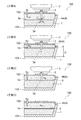
- a valve (not shown) provided in the ladle 2 is opened, and the molten stainless steel 1 in the ladle 2 flows down in the long nozzle 3 by the action of gravity and flows into the internal space 101 a of the tundish 101. That is, the inside of the tundish 101 is in the state shown in step A of FIG.
- the flowing stainless molten steel 1 is sealed by the Ar gas 4a filled in the internal space 101a and does not come into contact with air. Therefore, nitrogen (N 2 ) contained in the air and soluble in the stainless molten steel 1 The increase in N 2 component due to the penetration into the molten stainless steel 1 is suppressed.
- the surface 1a rises by the molten stainless steel 1 flowing in one after another.
- the rising surface 1a is in the vicinity of the spout 3a of the long nozzle 3
- the squeezing of the surface 1a by the molten stainless steel 1 flowing down from the spout 3a is reduced and the amount of surrounding gas is reduced.
- the TD powder 5 is sprayed toward the surface 1a of the molten steel 1.
- the TD powder 5 is sprayed so as to cover the entire surface 1a.
- nitrogen (N 2 ) gas 4b which is an inert gas, is injected from the gas supply nozzle 102 in place of the Ar gas 4a.
- the TD powder 5 deposited in layers on the surface 1a of the molten stainless steel 1 blocks the contact between the surface 1a of the molten stainless steel 1 and the N 2 gas 4b, and the N 2 gas 4b dissolves into the molten stainless steel 1. prevent. Thereby, the contact between Ti contained as a component in the molten stainless steel 1 and the nitrogen component (N) is suppressed, and the generation of TiN is suppressed, so that generation of large inclusions due to TiN in the molten stainless steel 1 is suppressed. In the molten stainless steel 1 that has been cooled and solidified, TiN is prevented from being precipitated as large inclusions.
- Al 2 O 3 generated by the deoxidation process remains in the molten stainless steel 1 without being absorbed by the slag. Since Al 2 O 3 has a high melting point of 2020 ° C., it is precipitated and clustered in the molten stainless steel 1 and exists as large inclusions in the solidified stainless molten steel 1. Furthermore, Al 2 O 3 may precipitate in the stainless steel melt 1 to adhere and deposit on the inner side of the immersion nozzle 101d and in the vicinity thereof, thereby closing the immersion nozzle 101d.
- FeSiCa alloy and metallic calcium are added to the molten stainless steel 1 in the secondary refining process.
- These FeSiCa alloy and metallic calcium are calcium aluminate (12CaO ⁇ 7Al) with respect to Al 2 O 3 .
- 12CaO ⁇ 7Al 2 O 3 has a melting point of 1400 ° C. that is significantly lower than the melting point of Al 2 O 3 , and is dissolved and dispersed in the molten stainless steel 1.
- 12CaO ⁇ 7Al 2 O 3 is not precipitated and present as large inclusions in the molten stainless steel 1 unlike Al 2 O 3 , and further adheres to the inside of the immersion nozzle 101d and the vicinity thereof. It does not accumulate and occlude it.
- the use of FeSiCa alloy as the calcium-containing material may cause the Si content to deviate from the regulation value. Therefore, metallic calcium and a dolomite graphite layer described later are provided. It is preferable to use at least one of the immersion nozzles of the tundish 101 produced.
- the rising surface 1a immerses the spout 3a of the long nozzle 3 in the molten stainless steel 1, and further the depth of the molten stainless steel 1 in the internal space 101a becomes a predetermined depth D.
- the stopper 104 is raised. Thereby, the molten stainless steel 1 in the internal space 101a flows into the through hole 105a of the mold 105 through the immersion nozzle 101d, and casting starts. At the same time, the molten stainless steel 1 in the ladle 2 is continuously poured into the internal space 101a through the long nozzle 3, and new molten stainless steel 1 is replenished in the internal space 101a.
- the inside of the tundish 101 is in a state as shown in step B of FIG.
- the molten stainless steel 1 maintains a depth near the predetermined depth D, and the surface 1a of the molten stainless steel 1 is substantially constant.
- the outflow amount of the molten stainless steel 1 from the immersion nozzle 101d and the inflow amount of the molten stainless steel 1 through the long nozzle 3 are adjusted so as to be in the position.
- the long nozzle 3 When the depth of the molten stainless steel 1 in the internal space 101a is a predetermined depth D, the long nozzle 3 has a depth of about 100 to 150 mm from the surface 1a of the molten stainless steel 1 at the spout 3a. It is preferable to penetrate. When the long nozzle 3 penetrates deeper than the above depth, it becomes difficult to pour out the molten stainless steel 1 from the spout 3a due to the resistance caused by the internal pressure of the molten stainless steel 1 accumulated in the internal space 101a.
- the surface 1a of the molten stainless steel 1 controlled to be maintained in the vicinity of a predetermined position during casting may fluctuate, and the spout 3a may be exposed. This is because there is a possibility that the poured molten stainless steel 1 hits the surface 1a and entrains and mixes the N 2 gas 4b.
- the molten stainless steel 1 flowing into the through hole 105a of the mold 105 is cooled by a primary cooling mechanism (not shown) in the process of flowing through the through hole 105a, and the inner wall surface side of the through hole 105a is solidified to form a solidified shell 1ba.
- the mold powder is supplied to the inner wall surface of the through hole 105a from the tip 101f side of the immersion nozzle 101d.
- the mold powder melts in the slag on the surface of the molten stainless steel 1, prevents oxidation of the surface of the molten stainless steel 1 in the through hole 105a, lubricates between the mold 105 and the solidified shell 1ba, and in the through hole 105a. It plays a role of keeping the surface of the molten stainless steel 1 warm.
- a slab 1b is formed by the solidified shell 1ba and the unsolidified molten stainless steel 1 inside, and the slab 1b is sandwiched from both sides by the roll 106 and drawn downward.
- the drawn slab 1b is sprinkled and cooled by a secondary cooling mechanism (not shown) in the process of passing between the rolls 106, and completely solidifies the molten stainless steel 1 inside.
- the new slab 1b is formed in the mold 105 while the slab 1b is pulled out from the mold 105 by the roll 106, so that the continuous slab 1b extends from the mold 105 in the extending direction of the roll 106. Is formed.
- the slab-shaped stainless steel piece 1c is formed by cutting the slab 1b fed by the roll 106.
- the stopper 104 is controlled to adjust the open area of the inlet 101e of the immersion nozzle 101d so that the surface of the molten stainless steel 1 in the through hole 105a of the mold 105 has a constant height. Thereby, the inflow amount of the molten stainless steel 1 is controlled. Furthermore, the inflow amount of the molten stainless steel 1 through the long nozzle 3 from the ladle 2 is adjusted so as to be equal to the outflow amount of the molten stainless steel 1 from the inlet 101e. Thereby, the surface 1a of the molten stainless steel 1 in the inner space 101a of the tundish 101 is maintained at a substantially constant position in the vertical direction in a state where the depth of the molten stainless steel 1 is maintained in the vicinity of the predetermined depth D.
- the long nozzle 3 has the spout 3 a at the tip thereof immersed in the molten stainless steel 1.
- the casting state which maintained the position of the surface 1a of the molten stainless steel 1 in the vertical direction substantially constant while dipping the spout 3a in the molten stainless steel 1 in the tundish 101 is called a steady state. .
- the N 2 gas 4b is fed by the TD powder 5 into the molten stainless steel 1 The state where it was cut off from is maintained. Thereby, the penetration of N 2 gas 4b into the molten stainless steel 1 is prevented.
- the long nozzle 3 is removed from the ladle 2, and the long nozzle 3 is left in the tundish 101 and replaced with another ladle 2 containing the molten stainless steel 1. It is done.
- the long nozzle 3 is connected to the replaced ladle 2 again.
- the casting work is continuously performed during the replacement work of the ladle 2, and thus the surface 1 a of the molten stainless steel 1 in the inner space 101 a of the tundish 101 is lowered.
- the supply of the N 2 gas 4b to the internal space 101a is continued during the ladle replacement operation. Then, the inside of the tundish 101 is in a state as shown in Step C of FIG.
- the opening area of the inlet 101 e of the immersion nozzle 101 d is adjusted by the stopper 104 so that the surface 1 a of the molten stainless steel 1 does not fall below the spout 3 a of the long nozzle 3 in the internal space 101 a. Then, the outflow amount of the molten stainless steel 1, that is, the casting speed is controlled.
- the slab 1b By continuously casting the molten stainless steel 1 in the plurality of ladles 2 as described above, in the slab 1b, it is possible to eliminate a seam caused when the ladle 2 is replaced. Further, the quality of the cast slab 1b is reduced at the initial stage of casting each time the ladle 2 changes. And the omission of the process until the molten stainless steel 1 is stored in the tundish 101, which is a process necessary when the casting is finished for each ladle 2, and the casting is started can be omitted.
- the surface 1a and the TD powder 5 are not disturbed due to the new flowing-down of the molten stainless steel 1, the penetration of the N 2 gas 4b into the molten stainless steel 1 is prevented until the end of casting.
- the distance between the spout 3a and the bottom of the main body 101b of the tundish 101 is short. That is, the distance between the spout 3a and the surface 1a of the molten stainless steel 1 is short, and the squeezing of the surface 1a by the molten stainless steel 1 is limited to the short time until the spout 3a is immersed, so that the stainless molten steel 1 can be obtained. Mixing of air and Ar gas 4a is reduced.
- N 2 gas 4b is used as the sealing gas instead of Ar gas, or TD powder 5 is sprayed on the surface 1a and N is used as the sealing gas.
- N 2 gas 4b may be excessively dissolved in molten stainless steel 1 to make its components incompatible as a product and to cause a large amount of inclusions due to TiN. For this reason, it may be necessary to discard all of the stainless steel pieces 1c cast from the molten stainless steel 1 stored in the internal space 101a at the beginning of casting until the spout 3a of the long nozzle 3 is immersed.
- the components of the molten stainless steel 1 can be kept within a required range without being changed, and TiN can be prevented from being generated. Further, Al 2 O 3 produced in the secondary refining process is changed to 12CaO ⁇ 7Al 2 O 3 by at least one of FeSiCa alloy and metallic calcium and dissolved in the molten stainless steel 1. Therefore, since the stainless steel piece 1c cast from the molten stainless steel 1 mixed with a slight amount of air or Ar gas 4a at the beginning of casting does not include large inclusions and has a required component configuration, the mixed Ar gas After surface cutting for removing bubbles generated by 4a, it can be used as a product.
- the stainless steel piece 1c cast at a time other than the initial stage of casting which occupies most of the casting time from the beginning of casting to the end of casting, is not affected by the air and Ar gas 4a mixed in the initial stage of casting.
- the TD powder 5 prevents the N 2 gas 4b from being mixed. For this reason, the stainless steel piece 1c cast at a time other than the initial stage of casting does not increase the nitrogen content from the state after the secondary refining, and also prevents the occurrence of surface defects due to bubble formation of the mixed gas.
- the molten stainless steel 1 is cut off from the N 2 gas 4b by the TD powder 5, the amount of TiN produced in the molten stainless steel 1 is greatly suppressed. Furthermore, Al 2 O 3 produced in the secondary refining process is changed to 12CaO ⁇ 7Al 2 O 3 by at least one of FeSiCa alloy and metallic calcium and dissolved in the molten stainless steel 1. Therefore, the stainless steel piece 1c cast at a time other than the initial stage of casting is largely suppressed from occurrence of surface defects due to large inclusions and bubbles, and can be used as a product as it is.
- Embodiment 2 In the continuous casting method according to Embodiment 2 of the present invention, the FeSiCa alloy and metallic calcium are not added to the molten stainless steel 1 in the secondary refining process in the continuous casting method according to Embodiment 1, and the tundish 101 is used. A dolomite graphite layer covering the inner wall surface of the immersion nozzle is formed.
- the same reference numerals as those in the previous drawings are the same or similar components, and thus detailed description thereof is omitted.
- an immersion nozzle 101 d extends from the bottom of the main body 101 b of the tundish 101 of the continuous casting apparatus 100 into the through hole 105 a of the mold 105 in the same manner as in the first embodiment. Furthermore, the entire inner wall surface of the immersion nozzle 101d and the inner wall surface of the tip 101f are respectively covered with inner layers 201d and 201f made of dolomite graphite. The inner layer 201d forms an inlet 201e into which the stopper 104 is fitted.
- Dolomite graphite contains MgO (magnesium oxide), CaO (calcium oxide) and C (carbon) as components.
- MgO magnesium oxide
- CaO calcium oxide
- C carbon
- dolomite graphite reacts as shown in the following formula (1) to change Al 2 O 3 to 12CaO ⁇ 7Al 2 O 3 having a low melting point. 7Al 2 O 3 + 12CaO ⁇ 12CaO ⁇ 7Al 2 O 3 Formula (1) Therefore, dolomite graphite has the same effect as the FeSiCa alloy and metallic calcium added to the molten stainless steel 1 in the first embodiment.
- the dolomite graphite of the inner layers 201d and 201f constitutes a Ca-containing material.
- the contained Al 2 O 3 changes to 12CaO ⁇ 7Al 2 O 3 and is dissolved and dispersed in the stainless molten steel 1. Therefore, adhesion and deposition of Al 2 O 3 on the immersion nozzle 101d and its periphery are suppressed, and surface defects are caused by Al 2 O 3 being precipitated as large inclusions in the cast stainless steel piece 1c. Is greatly suppressed. Further, since dolomite graphite is not added to the molten stainless steel 1 in the tundish 101, the layer of the TD powder 5 covering the molten stainless steel 1 is not disturbed. As a result, the N 2 gas 4b is prevented from melting into the molten stainless steel 1 through the disturbed TD powder 5, and the occurrence of surface defects due to precipitation of TiN as large inclusions is greatly suppressed.
- the continuous casting method in the second embodiment since other configurations and operations related to the continuous casting method according to the second embodiment of the present invention are the same as those in the first embodiment, description thereof will be omitted. Furthermore, according to the continuous casting method in the second embodiment, the same effect as the continuous casting method in the first embodiment can be obtained. Further, the inner layers 201d and 201f made of dolomite graphite in the second embodiment may be applied to the immersion nozzle 101d in the first embodiment. Thereby, Al 2 O 3 in the molten stainless steel 1 is more reliably changed to 12CaO ⁇ 7Al 2 O 3 .
- Examples 1 to 3 correspond to the continuous casting method of Embodiment 1, and are examples in which FeSiCa alloys are added in the secondary refining process.
- Example 4 corresponds to the continuous casting method of Embodiment 1, and is an example in which metallic calcium is added in the secondary refining process.
- Example 5 corresponds to the continuous casting method of Embodiment 2, and is an example in which a layer made of dolomite graphite is provided on the inner wall surface of a tundish immersion nozzle.
- the standard of the chemical composition of stainless steel in Example 5 is the same as the standard of the chemical composition of stainless steel in Example 4.
- Comparative Example 1 is a continuous casting method according to the first embodiment, in which the Ca-containing material is not added with FeSiCa alloy and metallic calcium in the secondary refining process, and is a stainless steel covered with TD powder in the tundish. In this example, a CaSi wire is introduced.
- Examples 1 to 5 are shown for the ratio of the number of slabs in which bubble defects were detected from a number of manufactured slabs and the ratio of the number of slabs in which defects due to inclusions were detected from the slabs.
- a comparison was made between the combined results and the results of Comparative Example 1.
- Table 3 for Examples 1 to 5, the results when the surface slab is not ground and when the surface is ground are shown, and for Comparative Example 1, the results when the surface is not ground are shown.
- the surface of the slab was ground with a thickness of 2 mm on one side (4 mm thickness on both sides).
- FIG. 5 is a comparison of the deposition state of deposits with a tundish immersion nozzle during slab casting in Examples 1 to 5.
- the horizontal axis indicates the length of continuously cast stainless steel
- the vertical axis indicates the deviation of the stopper (see the stopper 104 in FIG. 2).
- the stopper deviation is a vertical displacement of the stopper when the inlet of the tundish immersion nozzle (see the inlet 101e in FIG. 1 and the inlet 201e in FIG. 4) is closed. That is, the stopper deviation is zero when there is no deposit attached to the inlet of the immersion nozzle.
- deposits accumulate at the inlet of the immersion nozzle, the position of the stopper when closed is shifted upward, but this deviation amount becomes the stopper deviation.
- the deviation of the stopper reaches 5 mm, it is assumed that the inlet of the immersion nozzle is clogged with precipitates.
- Example 5 in Examples 1 to 3, even when the casting length is extended, the stopper deviation changes in the same manner around 1 mm, and the inlet of the immersion nozzle does not block. In Example 4, even if the casting length is extended, the stopper deviation similarly changes around 3 mm, and the inlet of the immersion nozzle is not blocked. In Example 5, even if the casting length is extended, the stopper deviation only reaches about 2.5 mm, and the inlet of the immersion nozzle is not blocked.
- the present invention is applied to steel types containing Ti as a component, such as 18Cr-1Mo-0.5Ti series and 22Cr-1.2Mo-Nb-Ti series stainless steels. It was confirmed that the surface defect inhibiting effect and the immersion nozzle blockage prevention as shown can be obtained.
- the continuous casting method according to Embodiments 1 and 2 has been described for stainless steel containing Ti as a component, but when applied to a stainless steel that requires aluminum deoxidation in the secondary refining process and also contains Nb as a component. It is effective.
- the continuous casting method which concerns on Embodiment 1 and 2 was applied to manufacture of stainless steel, you may apply to manufacture of another metal.
- the control in the tundish 101 in the continuous casting method according to the first and second embodiments has been applied to continuous casting, but may be applied to other casting methods.
Landscapes
- Engineering & Computer Science (AREA)
- Mechanical Engineering (AREA)
- Continuous Casting (AREA)
- Treatment Of Steel In Its Molten State (AREA)
- Casting Support Devices, Ladles, And Melt Control Thereby (AREA)
Priority Applications (6)
| Application Number | Priority Date | Filing Date | Title |
|---|---|---|---|
| US15/025,206 US9713839B2 (en) | 2013-09-27 | 2014-09-24 | Continuous casting method |
| EP14848812.5A EP3050644B1 (en) | 2013-09-27 | 2014-09-24 | Continuous casting method |
| MYPI2016701075A MY190292A (en) | 2013-09-27 | 2014-09-24 | Continuous casting method |
| CN201480053581.3A CN105682828A (zh) | 2013-09-27 | 2014-09-24 | 连续铸造方法 |
| ES14848812T ES2825102T3 (es) | 2013-09-27 | 2014-09-24 | Método de colada continua |
| KR1020167009986A KR102220411B1 (ko) | 2013-09-27 | 2014-09-24 | 연속 주조 방법 |
Applications Claiming Priority (4)
| Application Number | Priority Date | Filing Date | Title |
|---|---|---|---|
| JP2013200834 | 2013-09-27 | ||
| JP2013-200834 | 2013-09-27 | ||
| JP2014192187A JP6228524B2 (ja) | 2013-09-27 | 2014-09-22 | 連続鋳造方法 |
| JP2014-192187 | 2014-09-22 |
Publications (1)
| Publication Number | Publication Date |
|---|---|
| WO2015046238A1 true WO2015046238A1 (ja) | 2015-04-02 |
Family
ID=52743373
Family Applications (1)
| Application Number | Title | Priority Date | Filing Date |
|---|---|---|---|
| PCT/JP2014/075268 Ceased WO2015046238A1 (ja) | 2013-09-27 | 2014-09-24 | 連続鋳造方法 |
Country Status (9)
| Country | Link |
|---|---|
| US (1) | US9713839B2 (enExample) |
| EP (1) | EP3050644B1 (enExample) |
| JP (1) | JP6228524B2 (enExample) |
| KR (1) | KR102220411B1 (enExample) |
| CN (1) | CN105682828A (enExample) |
| ES (1) | ES2825102T3 (enExample) |
| MY (1) | MY190292A (enExample) |
| TW (1) | TWI654041B (enExample) |
| WO (1) | WO2015046238A1 (enExample) |
Families Citing this family (5)
| Publication number | Priority date | Publication date | Assignee | Title |
|---|---|---|---|---|
| KR101790001B1 (ko) * | 2016-03-02 | 2017-11-20 | 주식회사 포스코 | 용융물 주입 장치, 이를 이용한 주조설비 및 주조방법 |
| CN111032248B (zh) * | 2017-08-30 | 2021-11-09 | 杰富意钢铁株式会社 | 钢的连续铸造方法及薄钢板的制造方法 |
| CN110153388A (zh) * | 2019-06-21 | 2019-08-23 | 苏州大学 | 一种减少连铸坯中气泡缺陷的方法 |
| IT202000014383A1 (it) * | 2020-06-16 | 2021-12-16 | Danieli Off Mecc | Impianto per la produzione di acciaio e relativo metodo |
| CN114130977B (zh) * | 2021-11-24 | 2023-07-04 | 山东钢铁集团日照有限公司 | 一种减小高钛合金钢中氮化钛夹杂尺寸的方法 |
Citations (4)
| Publication number | Priority date | Publication date | Assignee | Title |
|---|---|---|---|---|
| JPH01122644A (ja) * | 1987-11-06 | 1989-05-15 | Toshiba Ceramics Co Ltd | 鋳造用ノズル |
| JPH03183721A (ja) * | 1989-12-12 | 1991-08-09 | Nippon Steel Corp | 溶鋼のカルシウム処理方法 |
| JPH04284945A (ja) | 1991-03-12 | 1992-10-09 | Nisshin Steel Co Ltd | Ti含有鋼の無手入れ連鋳スラブの製造法 |
| JPH0639505A (ja) * | 1992-07-28 | 1994-02-15 | Sumitomo Metal Ind Ltd | チタン含有ステンレス溶鋼の鋳造方法 |
Family Cites Families (26)
| Publication number | Priority date | Publication date | Assignee | Title |
|---|---|---|---|---|
| JPS57184563A (en) * | 1981-05-06 | 1982-11-13 | Kawasaki Steel Corp | Powder for surface coating of molten metal in continuous casting |
| GB9206946D0 (en) * | 1992-03-31 | 1992-05-13 | Foseco Int | Tundish cover layer |
| JP2613525B2 (ja) | 1992-06-22 | 1997-05-28 | 川崎製鉄株式会社 | 冷延用アルミキルド鋼の連続鋳造方法 |
| JPH0857599A (ja) | 1994-08-26 | 1996-03-05 | Nisshin Steel Co Ltd | タンディッシュ内スラグの除去方法および装置ならびに連続鋳造装置 |
| NL1001976C2 (nl) | 1995-12-22 | 1997-06-24 | Hoogovens Groep Bv | Werkwijze en inrichting voor het continu gieten van staal. |
| US5902511A (en) * | 1997-08-07 | 1999-05-11 | North American Refractories Co. | Refractory composition for the prevention of alumina clogging |
| AUPP406798A0 (en) | 1998-06-12 | 1998-07-02 | Bhp Steel (Jla) Pty Limited | Strip casting apparatus |
| JP3395699B2 (ja) * | 1999-03-18 | 2003-04-14 | 住友金属工業株式会社 | フェライト系ステンレス鋼の製造方法 |
| KR100579396B1 (ko) * | 2001-12-11 | 2006-05-12 | 주식회사 포스코 | 질화티타늄 개재물 흡수능이 높은 턴디쉬 플럭스 |
| JP4249940B2 (ja) * | 2002-04-30 | 2009-04-08 | 黒崎播磨株式会社 | アルミキルド鋼の鋳造方法 |
| KR101153780B1 (ko) * | 2004-02-11 | 2012-06-13 | 타타 스틸 리미티드 | 강철 용해 과정에 있어서 코어드 와이어 주입 방법 |
| KR100971260B1 (ko) * | 2004-03-15 | 2010-07-20 | 구로사키 하리마 코포레이션 | 연속 주조 노즐 |
| CN201082464Y (zh) * | 2007-05-29 | 2008-07-09 | 江苏沙钢集团有限公司 | 金属液连续浇注装置 |
| BRPI0904814B1 (pt) * | 2008-11-25 | 2020-11-10 | Maverick Tube, Llc | método de fabricação de um produto de aço |
| JP5316327B2 (ja) | 2009-02-09 | 2013-10-16 | 新日鐵住金株式会社 | 鋼の連続鋳造方法 |
| US8042602B2 (en) * | 2009-06-16 | 2011-10-25 | Nucor Corporation | High efficiency plant for making steel |
| CN101618454B (zh) | 2009-07-29 | 2011-07-20 | 四川大学 | 用于铝及铝合金的含钒细化剂及其制备方法 |
| CN201644737U (zh) * | 2010-03-24 | 2010-11-24 | 宝山钢铁股份有限公司 | 一种用于中间包的氩封装置 |
| US8828117B2 (en) * | 2010-07-29 | 2014-09-09 | Gregory L. Dressel | Composition and process for improved efficiency in steel making |
| JP5429120B2 (ja) * | 2010-09-17 | 2014-02-26 | 新日鐵住金株式会社 | 連々続鋳造方法 |
| CN102212748B (zh) * | 2011-02-21 | 2012-08-29 | 宁波钢铁有限公司 | 一种热轧钢卷的生产方法 |
| CN102212757B (zh) * | 2011-06-10 | 2013-01-16 | 江阴市恒润重工股份有限公司 | 一种用于大型风电装置的合金钢及其工件的制造工艺 |
| CN102816979B (zh) | 2012-08-27 | 2013-12-25 | 武汉钢铁(集团)公司 | 一种低碳硫系易切削钢连铸坯的生产方法 |
| CN103014221B (zh) * | 2012-12-17 | 2015-04-08 | 莱芜钢铁集团有限公司 | 一种生产高铝钢板坯的方法 |
| KR102084741B1 (ko) | 2013-08-26 | 2020-03-04 | 닛테츠 닛신 세이코 가부시키가이샤 | 연속 주조 방법 |
| KR102084729B1 (ko) | 2013-08-26 | 2020-03-04 | 닛테츠 닛신 세이코 가부시키가이샤 | 연속 주조 방법 |
-
2014
- 2014-09-22 JP JP2014192187A patent/JP6228524B2/ja active Active
- 2014-09-24 CN CN201480053581.3A patent/CN105682828A/zh active Pending
- 2014-09-24 EP EP14848812.5A patent/EP3050644B1/en active Active
- 2014-09-24 WO PCT/JP2014/075268 patent/WO2015046238A1/ja not_active Ceased
- 2014-09-24 MY MYPI2016701075A patent/MY190292A/en unknown
- 2014-09-24 KR KR1020167009986A patent/KR102220411B1/ko active Active
- 2014-09-24 ES ES14848812T patent/ES2825102T3/es active Active
- 2014-09-24 US US15/025,206 patent/US9713839B2/en active Active
- 2014-09-26 TW TW103133525A patent/TWI654041B/zh active
Patent Citations (4)
| Publication number | Priority date | Publication date | Assignee | Title |
|---|---|---|---|---|
| JPH01122644A (ja) * | 1987-11-06 | 1989-05-15 | Toshiba Ceramics Co Ltd | 鋳造用ノズル |
| JPH03183721A (ja) * | 1989-12-12 | 1991-08-09 | Nippon Steel Corp | 溶鋼のカルシウム処理方法 |
| JPH04284945A (ja) | 1991-03-12 | 1992-10-09 | Nisshin Steel Co Ltd | Ti含有鋼の無手入れ連鋳スラブの製造法 |
| JPH0639505A (ja) * | 1992-07-28 | 1994-02-15 | Sumitomo Metal Ind Ltd | チタン含有ステンレス溶鋼の鋳造方法 |
Non-Patent Citations (1)
| Title |
|---|
| See also references of EP3050644A4 |
Also Published As
| Publication number | Publication date |
|---|---|
| MY190292A (en) | 2022-04-12 |
| JP6228524B2 (ja) | 2017-11-08 |
| ES2825102T3 (es) | 2021-05-14 |
| KR20160067864A (ko) | 2016-06-14 |
| KR102220411B1 (ko) | 2021-02-24 |
| EP3050644A4 (en) | 2017-04-26 |
| EP3050644B1 (en) | 2020-08-19 |
| US9713839B2 (en) | 2017-07-25 |
| EP3050644A1 (en) | 2016-08-03 |
| JP2015085387A (ja) | 2015-05-07 |
| US20160228945A1 (en) | 2016-08-11 |
| CN105682828A (zh) | 2016-06-15 |
| TW201521912A (zh) | 2015-06-16 |
| TWI654041B (zh) | 2019-03-21 |
Similar Documents
| Publication | Publication Date | Title |
|---|---|---|
| JP6228524B2 (ja) | 連続鋳造方法 | |
| JP6493635B1 (ja) | 鋼の連続鋳造方法および薄鋼板の製造方法 | |
| TWI617377B (zh) | 連續鑄造方法 | |
| JP6154708B2 (ja) | 連続鋳造方法 | |
| JP6323973B2 (ja) | 連続鋳造方法 | |
| JP5965186B2 (ja) | 連続鋳造方法 | |
| TWI593482B (zh) | 連續鑄造方法 | |
| CN106755731B (zh) | 一种双联工艺生产低碳焊丝钢的方法 |
Legal Events
| Date | Code | Title | Description |
|---|---|---|---|
| 121 | Ep: the epo has been informed by wipo that ep was designated in this application |
Ref document number: 14848812 Country of ref document: EP Kind code of ref document: A1 |
|
| REEP | Request for entry into the european phase |
Ref document number: 2014848812 Country of ref document: EP |
|
| WWE | Wipo information: entry into national phase |
Ref document number: 2014848812 Country of ref document: EP |
|
| WWE | Wipo information: entry into national phase |
Ref document number: 15025206 Country of ref document: US |
|
| NENP | Non-entry into the national phase |
Ref country code: DE |
|
| ENP | Entry into the national phase |
Ref document number: 20167009986 Country of ref document: KR Kind code of ref document: A |