WO2015041196A1 - 光源装置およびプロジェクタ - Google Patents
光源装置およびプロジェクタ Download PDFInfo
- Publication number
- WO2015041196A1 WO2015041196A1 PCT/JP2014/074351 JP2014074351W WO2015041196A1 WO 2015041196 A1 WO2015041196 A1 WO 2015041196A1 JP 2014074351 W JP2014074351 W JP 2014074351W WO 2015041196 A1 WO2015041196 A1 WO 2015041196A1
- Authority
- WO
- WIPO (PCT)
- Prior art keywords
- light
- light source
- region
- lens
- lens array
- Prior art date
Links
Images


Classifications
-
- G—PHYSICS
- G03—PHOTOGRAPHY; CINEMATOGRAPHY; ANALOGOUS TECHNIQUES USING WAVES OTHER THAN OPTICAL WAVES; ELECTROGRAPHY; HOLOGRAPHY
- G03B—APPARATUS OR ARRANGEMENTS FOR TAKING PHOTOGRAPHS OR FOR PROJECTING OR VIEWING THEM; APPARATUS OR ARRANGEMENTS EMPLOYING ANALOGOUS TECHNIQUES USING WAVES OTHER THAN OPTICAL WAVES; ACCESSORIES THEREFOR
- G03B33/00—Colour photography, other than mere exposure or projection of a colour film
- G03B33/06—Colour photography, other than mere exposure or projection of a colour film by additive-colour projection apparatus
-
- G—PHYSICS
- G02—OPTICS
- G02B—OPTICAL ELEMENTS, SYSTEMS OR APPARATUS
- G02B27/00—Optical systems or apparatus not provided for by any of the groups G02B1/00 - G02B26/00, G02B30/00
- G02B27/48—Laser speckle optics
-
- G—PHYSICS
- G03—PHOTOGRAPHY; CINEMATOGRAPHY; ANALOGOUS TECHNIQUES USING WAVES OTHER THAN OPTICAL WAVES; ELECTROGRAPHY; HOLOGRAPHY
- G03B—APPARATUS OR ARRANGEMENTS FOR TAKING PHOTOGRAPHS OR FOR PROJECTING OR VIEWING THEM; APPARATUS OR ARRANGEMENTS EMPLOYING ANALOGOUS TECHNIQUES USING WAVES OTHER THAN OPTICAL WAVES; ACCESSORIES THEREFOR
- G03B21/00—Projectors or projection-type viewers; Accessories therefor
- G03B21/14—Details
- G03B21/20—Lamp housings
- G03B21/2006—Lamp housings characterised by the light source
- G03B21/2033—LED or laser light sources
-
- G—PHYSICS
- G03—PHOTOGRAPHY; CINEMATOGRAPHY; ANALOGOUS TECHNIQUES USING WAVES OTHER THAN OPTICAL WAVES; ELECTROGRAPHY; HOLOGRAPHY
- G03B—APPARATUS OR ARRANGEMENTS FOR TAKING PHOTOGRAPHS OR FOR PROJECTING OR VIEWING THEM; APPARATUS OR ARRANGEMENTS EMPLOYING ANALOGOUS TECHNIQUES USING WAVES OTHER THAN OPTICAL WAVES; ACCESSORIES THEREFOR
- G03B21/00—Projectors or projection-type viewers; Accessories therefor
- G03B21/14—Details
- G03B21/20—Lamp housings
- G03B21/208—Homogenising, shaping of the illumination light
-
- H—ELECTRICITY
- H04—ELECTRIC COMMUNICATION TECHNIQUE
- H04N—PICTORIAL COMMUNICATION, e.g. TELEVISION
- H04N9/00—Details of colour television systems
- H04N9/12—Picture reproducers
- H04N9/31—Projection devices for colour picture display, e.g. using electronic spatial light modulators [ESLM]
- H04N9/3141—Constructional details thereof
- H04N9/315—Modulator illumination systems
- H04N9/3161—Modulator illumination systems using laser light sources
Definitions
- the present invention relates to a light source device using a coherent light source such as a semiconductor laser that can be used in an optical device such as a projector.
- HID lamps high-intensity discharge lamps
- TM DLP
- liquid crystal projectors and photomask exposure apparatuses.
- FIG. 13 is a diagram for explaining one form of a part of a conventional projector related to the projector of the present invention (reference: Japanese Patent Application Laid-Open No. 2004-252112, etc.).
- a light condensing means (not shown) composed of a concave reflecting mirror, a lens, or the like.
- FmA is input to the incident end (PmiA) and output from the exit end (PmoA).
- a light guide can be used, which is also called a name such as a rod integrator or a light tunnel, and is a light transmissive material such as glass or resin.
- the light homogenizing means (FmiA) repeats total reflection on the side surface of the light homogenizing means (FmA). By propagating through FmA), even if the distribution of light input to the incident end (PmiA) is uneven, the illuminance on the exit end (PmoA) is sufficiently uniformed. Function.
- a hollow square tube the inner surface of which is a reflecting mirror
- the illumination lens (Ej1A) is arranged so that a square image of the emission end (PmoA) is formed on the two-dimensional light amplitude modulation element (DmjA), and is output from the emission end (PmoA).
- the two-dimensional light amplitude modulation element (DmjA) is illuminated with light.
- a mirror (MjA) is disposed between the illumination lens (Ej1A) and the two-dimensional light amplitude modulation element (DmjA). Then, the two-dimensional light amplitude modulation element (DmjA) modulates the light so as to be directed to the direction in which the light is incident on the projection lens (Ej2A) or not to be incident on each pixel according to the video signal. An image is displayed on the screen (Tj).
- the two-dimensional light amplitude modulation element as described above is sometimes called a light valve.
- the two-dimensional light amplitude modulation element (DmjA) is generally DMD (TM) (digital). ⁇ Micromirror devices are often used.
- FIG. 14 is a diagram for explaining one form of one kind (reference: Japanese Patent Laid-Open No. 2001-142141, etc.).
- the light from the light source (SjB) composed of a high-intensity discharge lamp or the like is made into a uniform light beam by a fly-eye integrator with the help of collimator means (not shown) composed of a concave reflecting mirror or lens.
- the light uniformizing means (FmB) is configured by a combination of an incident-side front stage fly-eye lens (F1B), an exit-side rear stage fly-eye lens (F2B), and an illumination lens (Ej1B).
- Both the front fly-eye lens (F1B) and the rear fly-eye lens (F2B) are formed by arranging a large number of rectangular lenses having the same focal length and the same shape in the vertical and horizontal directions.
- Each lens of the front-stage fly-eye lens (F1B) and the corresponding lens of the rear-stage fly-eye lens (F2B) in the subsequent stage constitute an optical system called Koehler illumination.
- a large number of optical systems are arranged vertically and horizontally.
- the Kohler illumination optical system is composed of two lenses.
- the front lens collects light and illuminates the target surface, the front lens does not form a light source image on the target surface, but the center of the rear lens.
- a light source image is formed on this surface, and the rear lens is arranged so as to form an image of the quadrangle of the outer shape of the front lens on the target surface (surface to be illuminated), thereby uniformly illuminating the target surface.
- the function of the latter lens is to prevent the phenomenon that the illuminance around the square of the target surface falls depending on the size when the light source is not a perfect point light source but has a finite size if it is not
- the rear lens can make the illuminance uniform to the periphery of the square of the target surface without depending on the size of the light source.
- the light uniformizing means (FmB) is basically inputted with a substantially parallel light beam
- the front fly-eye lens (F1B) and the rear fly-eye lens ( The distance from F2B) is set to be equal to the focal length thereof, and thus an image of the target surface of uniform illumination as the Kohler illumination optical system is generated at infinity.
- the illumination lens (Ej1B) is disposed at the rear stage of the rear fly-eye lens (F2B), the target surface is drawn toward the focal plane of the illumination lens (Ej1B) from infinity.
- the output light flux is also substantially axially symmetric. Because of the nature of the lens, that is, the Fourier transform action of the lens, all rays incident on the lens surface at the same angle are refracted toward the same point on the focal plane regardless of the incident position on the lens surface.
- the output of the Koehler illumination optical system is imaged on the same target surface on the focal plane of the illumination lens (Ej1B).
- a polarizing beam splitter (MjB) is disposed between the illumination lens (Ej1B) and the two-dimensional light amplitude modulation element (DmjB), so that light is transmitted to the two-dimensional light amplitude modulation element ( DmjB) is reflected.
- the two-dimensional light amplitude modulation element (DmjB) rotates the polarization direction of light by 90 degrees for each pixel according to the video signal, or modulates and reflects the light so that only the rotated light is reflected. Then, the light passes through the polarizing beam splitter (MjB) and is incident on the projection lens (Ej3B) to display an image on the screen (Tj).
- LCOS silicon liquid crystal device
- DmjA two-dimensional optical amplitude modulation element
- a polarization alignment function element (PcB) for rotating the direction by 90 degrees and, as a result, enabling effective use of all light is inserted, for example, in the rear stage of the rear fly-eye lens (F2B).
- F2B rear fly-eye lens
- Ej2B field lens
- DmjB two-dimensional light amplitude modulation element
- a transmissive liquid crystal device (LCD) is also used with an optical arrangement suitable for the same (reference: No. 10-133303).
- a dynamic color filter such as a color wheel is disposed after the light uniformizing means, and R, G, B (red and green, blue)
- the two-dimensional light amplitude modulation element is illuminated as a color sequential light beam, and color display is realized by time division, or a dichroic mirror or dichroic prism is arranged at the subsequent stage of the light uniformizing means, and R, G, B
- a dichroic mirror or dichroic prism to perform color synthesis of modulated light beams of the three primary colors R, G, and B
- FIGS. 13 and 14 it is omitted in order to avoid complication.
- the high-intensity discharge lamp described above has drawbacks such as low conversion efficiency from input power to optical power, that is, a large heat loss or a short life.
- solid light sources such as LEDs and semiconductor lasers have attracted attention as alternative light sources that have overcome these drawbacks.
- the LED has a smaller heat loss and a longer life than the discharge lamp, but the emitted light has no directivity like the discharge lamp.
- the light use efficiency is low.
- the heat loss is small, the lifetime is long, and the directivity is high, so that only light in a specific direction can be used, such as the projectors and exposure apparatuses described above.
- the light use efficiency is high.
- the high directivity makes it possible to perform optical transmission with high efficiency, so it is possible to separate the installation location of the semiconductor laser from the location where the light is used, such as a projector. The degree of freedom can be increased.
- the speckle is a coherent light generated by wavelength conversion of laser light from a semiconductor laser or other laser or laser light (using a nonlinear optical phenomenon such as harmonic generation or optical parametric effect).
- a granular and speckled pattern that inevitably appears when light is projected, and is used to generate images for viewing, such as the projector described above, and a photomask pattern on a coating made of a photosensitive material. Since the exposure is a very troublesome phenomenon that significantly deteriorates the image quality, many improvements have been proposed for a long time.
- the luminous flux is divided and overlapped in a cross section perpendicular to the optical axis, or the optical axis of the luminous flux
- the phase, polarization state, delay, etc. depending on the position of the cross section perpendicular to the surface are given, and the division state and the given state are changed with time by rotating, vibrating, or swinging the optical element.
- the most frequently used means is to use a diffusion plate.
- the speckle noise reduction ability increases as the degree of diffusion increases. Since there is a trade-off relationship in which the utilization efficiency is lowered, there are few that reduce speckle noise by relying on the function of the diffuser alone, and most of them use other means in combination as described above.
- Japanese Patent Application Laid-Open No. 51-064325 describes a technique for rotating a ground glass disk as a diffusion plate in a character pattern generator using a laser in order to prevent a decrease in resolution due to speckle.
- Japanese Patent Application Laid-Open No. 51-064325 describes a technique for rotating a ground glass disk as a diffusion plate in a character pattern generator using a laser in order to prevent a decrease in resolution due to speckle.
- the reason why the speckle noise reduction capability of the diffuser is high is that, for example, in the case of splitting the light beam by the beam splitter, the light beam is only split into two by one pass of the beam splitter. Then, at each point in the cross section perpendicular to the optical axis of the light beam, the light beam is divided into an infinite number of partial light beams, and a deflection angle including a random element is given. The divided partial light beams are immediately superimposed on the downstream side, and the speckles are subdivided, but the speckle noise is reduced by making the speckles fine enough to be subdivided sufficiently and difficult to see. . As shown in FIG.
- FIG. 15A which is a schematic diagram for explaining the concept of the prior art according to the present invention
- the angle distribution of the transmitted light has a peak in the axial direction with respect to the direction of the original incident parallel light beam (Li), that is, the optical axis (z), and the angle ( ⁇ ) formed with the axis is
- the distribution ratio decreases as the number increases.
- the distribution has a wide skirt, for example, a distribution (P ( ⁇ )) shown in FIG. 15B such as a Gaussian distribution.
- the central optical axis (peak of the angular distribution of transmitted light)
- the component around z) is not useful, and is a light component (Ap) that is separated from the center and has a distribution ratio lower than the peak, in the range of a certain lower limit angle ( ⁇ 1) or more and an upper limit angle ( ⁇ 2) or less.
- ⁇ 1 or more and ⁇ 2 or less Is responsible for speckle noise reduction.
- ⁇ 2 is a specific upper limit value of an angle at which a light beam can propagate through the inside to the end and can be effectively output depending on the NA in an optical system. .
- the diffuser plate has a transmitted light angle distribution that does not include components around the central axis that do not play a role in reducing speckle noise or components that belong to the tail that cannot be effectively used.
- An optical element that can be used instead of the above is considered, and specifically, a two-dimensional lens array can be used for this purpose.
- a haenocular lens that is, a two-dimensional lens array, or a lens having a lenticular sheet whose cylindrical lines are orthogonal to each other (that is, a crossed cylindrical lens array) can be suitably used.
- Japanese Patent Laid-Open No. 8-233544 discloses a three-dimensional shape measuring apparatus using a confocal optical system using a laser light source, in order to reduce noise due to interference fringes due to high coherence of the light source, thereby reducing the coherence.
- a technique for inserting a light diffusing means and vibrating or rotating it is described.
- a light diffusing means for example, a microlens array (in addition to a normal diffusing element, such as a ground glass, a surface having a scattering structure, a volume scattering material such as opal glass, a diffraction grating, and an optical fiber array with irregular end faces, etc. That is, a two-dimensional lens array) is used.
- JP-A-11-014551 discloses that a laser pattern is rotated with a microarray lens or a fly-eye lens (that is, a two-dimensional lens array) in a mask pattern defect inspection apparatus using ultraviolet laser light. A technique for eliminating coherence by passing a phase plate is described.
- Japanese Patent Laid-Open No. 2008-309827 discloses a technique for reducing speckle noise by inserting a rotating microlens array (that is, a two-dimensional lens array) immediately before a rod integrator in a projection type image display apparatus such as a projector. Are listed.
- FIG. 16 which is a diagram, square lenses are arranged vertically and horizontally, or rectangular lenses are arranged vertically and horizontally like the front stage fly-eye lens (F1B) and the rear stage fly-eye lens (F2B).
- F1B front stage fly-eye lens
- F2B rear stage fly-eye lens
- the lenticular lens has a large number of cylindrical lenses arranged.
- this will be hereinafter referred to as “lenticular lens”.
- FIG. 1A is an enlarged view of one unit square (S0) extracted from the unit squares included in the two-dimensional lens array (Lar ′) shown in FIG. It is the figure which looked at the surface (Hs) from the front, and a lower stage is a side view.
- the refracting surface (Hs) is a spherical surface and the refracting surface on the back side is a substrate surface (Hb), and is therefore a flat surface, and a parallel light beam is incident perpendicularly to this surface.
- the angle of the ray passing through the vertex or center of the refractive surface (Hs) does not change, according to the teaching of the paraxial theory of geometric optics, the light incident on the position shifted by the deviation radius (r) from the vertex is , It is deflected by an angle proportional to the deviation radius (r).
- the proportion of the distribution of light deflected by a certain angle ⁇ is the circumference of the circle (C1) having the deviation radius (r) corresponding to that angle. Since P is proportional to the length, P is proportional to 2 ⁇ r.
- the deviation radius (r) is larger than the radius (R) of the inscribed circle (C0) of the unit square (S0) (that is, half of the side length of the unit square (S0)), the divided circle (C2 ), And when multiplied by the ratio of the effective existence range angle ( ⁇ ) to the entire circumference, the distribution amount (P) as a function of the deviation radius (r) is eventually expressed in (b) of FIG. As described.
- the specific form of the function is as shown in the lower equation. However, the proportionality factor 2 ⁇ is reduced so that the peak is 1.
- the radius r corresponds to the deflection angle ⁇ ⁇
- the horizontal axis of the graph of FIG. 1B is viewed as ⁇ , and compared with the graph of FIG.
- the angle formed by the normal (n) of the refracting surface and the optical axis (z) at the position corresponding to the maximum value ⁇ 2 ⁇ R of the deviation radius (r). ( ⁇ ) may be obtained, and the maximum deflection angle ⁇ may be calculated according to Snell's law. As a result, the correspondence between the maximum value ⁇ 2 ⁇ R of the deviation radius (r) and the maximum deflection angle ⁇ is determined, and scaling is possible.
- the two-dimensional lens array has been described above, the same discussion can be made in the case of the crossed cylindrical lens array as shown in FIG. 17.
- the optical function is completely equivalent to the two-dimensional lens array (Lar ′) composed of spherical lenses.
- both the upper and lower cylindrical lens arrays are drawn such that a cylindrical lens is formed on the upper surface of the substrate.
- the upper cylindrical lens array has a cylindrical lens structure. The degree of approximation to the two-dimensional lens array (Lar ′) composed of spherical lenses is improved by arranging the formed side face downward and the upper and lower cylindrical lenses facing each other.
- the problem to be solved by the present invention is to provide a light source device and a projector that avoid the appearance of a periodic pattern superimposed on the transmitted light of a two-dimensional lens array for speckle reduction or a crossed cylindrical lens array.
- the light source device performs emission by mixing the light emission region (Gs) formed by the coherent light source (Sc) and the components of the angle and position of the incident light from the incident end (Pmi).
- a light source having a light mixing means (Fm) emitted from the end (Pmo) and a light beam matching optical system (Eu) for projecting a light beam emitted from the light emission region (Gs) onto the incident end (Pmi)
- the light beam matching optical system (Eu) includes a two-dimensional lens array (Lar) that functions as a light diffusing unit, and the two-dimensional lens array (Lar) has an effective area of at least It is composed of one sub-region (A1, A2,...), And the arrangement of the vertices (Lo1, Lo2,%) Of the individual lenses (L1, L2,7) Constituting the sub-region is aperiodic. It is characterized by Than is.
- the arrangement of the vertices (Lo1, Lo2,%) Of the lenses (L1, L2,%) In the sub-region (A1, A2,%) is based on a periodic arrangement.
- the arrangement of the vertices (Lo1, Lo2,%) Of the individual lenses (L1, L2,%) Constituting the sub-region (A1, A2,%) is characterized by being.
- the individual lenses (L1, L2,%) Constituting the sub-regions (A1, A2,%) are formed of cylindrical lens arrays (Lca1, Lca2) having different arrangement directions.
- Each cylindrical lens (Lc1, Lc2,%) which is formed by overlapping a plurality of lenses and constitutes the cylindrical lens array (Lca1, Lca2), has an inclination angle ( ⁇ 1) of its generatrix (Lx1, Lx2,). , ⁇ 2,... Are determined for each cylindrical lens.
- the individual lenses (L1, L2,%) Constituting the sub-regions (A1, A2,%) are formed of cylindrical lens arrays (Lca1, Lca2) having different arrangement directions.
- Each cylindrical lens (Lc1, Lc2, Lc3,%) Forming the cylindrical lens array (Lca1, Lca2) is formed by overlapping a plurality of lenses, and the busbars (Lx1, Lx2, Lx3,%) The bus interval (d1, d2,%) Between adjacent ones in the line is not uniform.
- a light source device is characterized in that the light mixing means (Fm) is a light guide that guides light while confining light in a predetermined space and performing multiple reflection of light.
- the light mixing means (Fm) is a light guide that guides light while confining light in a predetermined space and performing multiple reflection of light.
- the light source device is characterized in that the light mixing means (Fm) is a fly eye integrator.
- a projector for projecting and displaying an image using the light source device according to any one of the first to seventh aspects, wherein the light uniformizing means also serves as the light mixing means (Fm). Is.
- the schematic of the concept relevant to the technique of the light source device of this invention is represented.
- the block diagram which simplifies and shows the light source device of this invention is represented.
- the schematic diagram which simplifies and shows an example of a part of light source device of the present invention is shown.
- the schematic diagram which simplifies and shows an example of a part of light source device of the present invention is shown.
- the schematic diagram which simplifies and shows an example of a part of light source device of the present invention is shown.
- the schematic diagram which simplifies and shows an example of a part of light source device of the present invention is shown.
- the schematic diagram which simplifies and shows an example of a part of light source device of the present invention is shown.
- the schematic diagram which simplifies and shows an example of a part of light source device of the present invention is shown.
- the schematic diagram which simplifies and shows an example of a part of light source device of the present invention is shown.
- the figure which simplifies and shows one form of the Example of the light source device of this invention is represented.
- the figure which simplifies and shows one form of the Example of the projector of this invention is represented.
- the figure which simplifies and shows one form of the Example of the projector of this invention is represented.
- the figure explaining one form of one part of the kind of the conventional projector concerning the projector of this invention is represented.
- the figure explaining one form of one part of the kind of the conventional projector concerning the projector of this invention is represented.
- 1 represents a schematic diagram of concepts related to the prior art according to the present invention.
- the schematic diagram explaining the concept of the prior art concerning this invention is represented.
- the schematic diagram explaining the concept of the prior art concerning this invention is represented.
- the first cause of the periodic pattern appearing in the transmitted light of the two-dimensional lens array or the crossed cylindrical lens array in the prior art is that the two-dimensional lens array or the crossed cylindrical lens array has a periodic structure. . Since the light beam refracted, diffracted and scattered by the periodic structure undergoes periodic phase modulation, when superimposed on the downstream side of the optical system, a periodic pattern appears due to interference and is superimposed.
- the second cause is that the boundary between the lens constituting the two-dimensional lens array and the adjacent lens, or the boundary between the cylindrical lens constituting the crossed cylindrical lens array and the adjacent cylindrical lens is originally sharp in a V shape. What must be incised is actually a microscopically dull U-shape, and a sheet-like light beam that is nearly transparent is mixed into the transmitted light. It can be said that the second cause is a factor that exacerbates the essential problem caused by the first cause.
- FIG. 2 is a block diagram which simplifies and shows the light source device of this invention.
- the coherent light source (Sc) is a semiconductor laser
- the divergent light emitting portion present on the surface of the semiconductor chip housed in the semiconductor laser package is substantially treated as a point light source. This can be the light emission region (Gs).
- a light beam matching optical system (Eu) composed of a lens or the like receives a light beam (Bs) from the light radiation region (Gs) and receives a light mixing means (a rear stage) as a projection region for the light radiation region (Gs).
- a light beam (Bf) that forms a matching light radiation region (Gf) is output in the vicinity of the incident end (Pmi) of Fm).
- the luminous flux matching optical system (Eu) is provided with a two-dimensional lens array (Lar), which will be described later, in the interior, upstream or downstream, and a cross section perpendicular to the optical axis of the luminous flux with respect to the incident luminous flux. At each of the points, the light is divided into an infinite number of partial light beams, and converted into diffused light including a non-periodic element and having a deflection angle.
- the light mixing means (Fm) receives the light beam (Bf) from the light beam matching optical system (Eu) from the incident end (Pmi), and enters the light beam inside the light mixing means (Fm).
- the angle and position components are mixed, and a light beam (Bmo) is output from the emission end (Pmo).
- the output light beam (Bmo) is subject to multiple interference by mixing the angle and position components of the incident light beam. As a result, the speckled granular / spotted pattern on the illuminated surface is projected. The property of being fine and difficult to visually recognize is imparted.
- the two-dimensional lens array (Lar) has at least one effective region in which lenses are arranged.
- the two-dimensional lens array (Lar) has at least one effective region in which lenses are arranged.
- the arrangement of the vertices (Lo1, Lo2,%) Of the individual lenses (L1, L2,%) Constituting the sub-regions is aperiodic.
- the vertexes (Lo1, Lo2,%) are positions on the lenses (L1, L2,%) From which the light rays perpendicularly incident on the substrate surface are emitted without being deflected. Point to. Therefore, when the lenses (L1, L2,%) Are ordinary spherical lenses, the vertices (Lo1, Lo2,%) Coincide with the geometrical vertices of the refractive surfaces of the respective lenses.
- the substrate surface referred to here refers to the two-dimensional lens array (Lar) or the cylindrical lens arrays (Lca1, Lca2) described later, like the substrate surface (Hb) shown in FIG. It is the surface defined by the substrate that is the overall foundation to be constructed.
- the right side in the figure is an enlarged view of a part of the sub-region of the two-dimensional lens array (Lar) drawn on the left side.
- Polygonal regions surrounded by lens boundaries (Lb) represented by line segments represent individual lenses.
- This figure is drawn on the assumption that the lenses (L1, L2,%) Are spherical lenses, but may be, for example, a hologram lens.
- the arrangement of the lenses (L1, L2,%), In particular, the arrangement of the apexes (Lo1, Lo2,...) Is aperiodic, so that a two-dimensional lens array or a crossed cylindrical lens array in the prior art is used. It is possible to avoid the problem that the periodic patterns such as the stripe pattern and the lattice pattern appear to be superimposed due to the fact that has a periodic structure.
- the periodicity of the lenses may appear.
- the sub area (A2, A3, A4) may be configured by copying the sub area (A1). This is because, in such a configuration, although it has periodicity, the period is very large, so that the periodic pattern that appears due to interference becomes fine and becomes substantially invisible.
- the semiconductor laser includes not only a single active region but also a plurality of emitting portions.
- a semiconductor laser array device in which active regions are arranged in a row and divergent light is emitted from each active region can also be used.
- a plurality of single active region semiconductor lasers and semiconductor laser array devices are provided, and a plurality of divergent light beams from them are combined by a lens system, and the light emitting region (Gs) is formed as an aggregate of a plurality of point light sources. In the present specification, these are referred to as a semiconductor laser light source unit.
- a core image of an emission end of an optical fiber into which light of a semiconductor laser or a semiconductor laser array device is input from an incident end is used as the light emission. It can also be a region (Gs). Furthermore, an emission end of an optical fiber bundle in which a plurality of such optical fibers are bundled and a plurality of emission ends are densely arranged can be used as the light emission region (Gs).
- the present invention can be applied not only to a semiconductor laser but also to any device that uses the above-described coherent light emitter that can generate speckle as a light source.
- the position of the vertex when the positional deviation ( ⁇ x, ⁇ y) is given to the vertex of each lens is represented by a mark in which a cross is drawn in a circle. It turns out that it has shifted
- the arrangement of the vertical and horizontal lenses in the two-dimensional lens array (Lar) is regarded as a matrix, and the positional deviation ⁇ x in the x direction of the lenses in a certain row is When viewed in order, a random number array is formed, and when a positional deviation ⁇ y in the y direction of lenses in the same row is viewed from the left, a random number array is formed, and the other rows are similarly viewed.
- a random number array is formed, and when the positional deviation ⁇ y in the y direction of the lens in the same column is viewed from the top, a random number array is formed. It can be random, i.e. random.
- an aperiodic numerical sequence may be generated based on, for example, a mathematical deterministic algorithm.
- the magnitude of this vector is the same for all lenses, and the direction depends on the lens. For example, it may be changed randomly.
- each of the lenses (L1, L2, L2) constituting the sub-region (A1, A2, etc.)) May be configured so that the arrangement of the vertices (Lo1, Lo2,...) Is random.
- the positions of the vertices are represented by marks drawn with a cross in a circle, and the polygonal region surrounded by the lens boundary (Lb) represented by a line segment represents each lens.
- the arrangement of the vertices (Lo1, Lo2,...) May be random in a mathematically strict sense.
- the arrangement is not limited to this, and it may be a random appearance (pseudorandom). Often, the arrangement of this figure corresponds to the latter.
- FIG. 5 is a schematic diagram showing a simplified example of a part of the light source device of the present invention, each extending in the direction (that is, the long side).
- the case where there are two partial sub-regions (Ac11, Ac12) and partial sub-regions (Ac21, Ac22) orthogonal to each other is depicted.
- each of the cylindrical lenses (Lc1, Lc2,...) Is assumed to be parallel (or substantially parallel) to the short side of the partial sub-region, for example.
- the cylindrical lens arrays (Lca1, Lca2) are superposed vertically, and each of the partial subregions (Ac11, Ac12) and the partial subregions (Ac21, Ac22). ), A total of four sub-regions (A1, A2, A3, A4) having the shape shown on the left in FIG. 3 are formed.
- the direction of the generatrix of the upper and lower cylindrical lens arrays is orthogonal (or substantially orthogonal), and therefore has an optical function equivalent to that of the two-dimensional lens array. It becomes.
- each of the cylindrical lens arrays has four partial sub-regions, and when the cylindrical lens arrays (Lca1, Lca2) are overlapped, the partial sub-regions correspondingly overlap each other.
- You may comprise as follows. When two cylindrical lens arrays are stacked, it is desirable that the upper and lower cylindrical lenses face each other as described above.
- two cylindrical lens arrays are overlapped so that the directions of the generatrix are orthogonal (or substantially orthogonal), but three or more cylindrical lens arrays may be overlapped, and the direction of the generatrix May form an angle other than a right angle.
- the reason why it is described as being substantially parallel or substantially orthogonal is that there is a configuration in which the directions of the generatrix of individual cylindrical lenses belonging to one partial sub-region described later are not parallel to each other. Because it does.
- FIG. 6 is a schematic diagram showing a simplified example of a part of the light source device of the present invention.
- Constituting the cylindrical lens array (Lca1) are parallel or inclined with respect to the reference direction (y).
- the positive and negative tilt angles ( ⁇ 1, ⁇ 2,%) Are given for each cylindrical lens.
- the tilt angles ( ⁇ 1, ⁇ 2,%) For example, when the cylindrical lenses are viewed in order from the top, the respective tilt angles are enumerated to form a random number array, that is, random.
- an aperiodic numerical sequence may be generated based on, for example, a mathematical deterministic algorithm.
- the generating line of the cylindrical lens is represented by a one-dot chain gland, and the lens boundary (Lcb) of adjacent cylindrical lenses is represented by a solid line.
- FIG. 7 is a schematic diagram illustrating a simplified example of a part of the above, is illustrated.
- the projections of the lens boundaries (Lcbx, Lcby) of the individual cylindrical lenses on the sub-region surface in the upper and lower cylindrical lens arrays are represented by solid lines, and the generatrix (Lx, Ly) of the individual cylindrical lenses are represented by solid lines.
- the projection onto the sub-region plane is represented by a one-dot chain line.
- the intersections (Lo) of the vertical and horizontal generatrixes are also aperiodically arranged.
- the quadrangular region surrounded by the solid line of the lens boundary and the intersection (Lo) of the generatrix are the lens (L1, L2,.
- the arrangement of the vertices of the spherical lenses is aperiodic. It can be seen that an optical element equivalent to the two-dimensional lens array can be realized.
- FIG. 8 is a schematic view showing another example of the cylindrical lens array (Lca1, Lca2) in a simplified manner as an example of a part of the light source device of the present invention.
- the cylindrical lens array (Lca1, Lca2) of this figure is adjacent to the adjacent ones in the arrangement of the respective busbars (Lx1, Lx2, Lx3,...) Of the individual cylindrical lenses (Lc1, Lc2, Lc3,...) Constituting the cylindrical lens array (Lca1, Lca2).
- the arrangement positions of the cylindrical lenses are determined so that the bus interval (d1, d2,...) Is not uniform.
- the respective bus interval is enumerated to form a random number array, that is, random.
- an aperiodic numerical sequence may be generated based on, for example, a mathematical deterministic algorithm.
- the generating line of the cylindrical lens is represented by a one-dot chain gland, and the lens boundary (Lcb) of adjacent cylindrical lenses is represented by a solid line.
- FIG. 9 is a schematic diagram showing a simplified example of a part of the above.
- the projections of the lens boundaries (Lcbx, Lcby) of the individual cylindrical lenses on the sub-region surface in the upper and lower cylindrical lens arrays are represented by solid lines, and the generatrix (Lx, Ly) of the individual cylindrical lenses are represented by solid lines.
- the projection onto the sub-region plane is represented by a one-dot chain line.
- the intersections (Lo) of the vertical and horizontal generatrixes are also aperiodically arranged.
- the quadrangular region surrounded by the solid line of the lens boundary and the intersection (Lo) of the generatrix are the lens (L1, L2,%) And the vertex ( Corresponds to Lo1, Lo2,. Therefore, in the crossed cylindrical lens array formed by superimposing the two cylindrical lens arrays (Lca1, Lca2) configured as described above vertically as described above, the arrangement of the vertices of the spherical lenses is aperiodic. It can be seen that an optical element equivalent to the two-dimensional lens array can be realized.
- One of the advantages of constructing one two-dimensional lens array (Lar) with a crossed cylindrical lens array is that the maximum deflection angle of the upper and lower cylindrical lens arrays is different so that the direction distribution of diffused light is non-axial. It is easy to realize a diffusing plate that is symmetrical. For example, it is possible to make a diffusing plate with the z axis as the optical axis and strong diffusion in the x axis direction and weak diffusion in the y axis direction. Specifically, with respect to the individual cylindrical lenses of the cylindrical lens array whose diffusion is to be increased, the focal length is shortened, or if the focal length is the same, the bus interval is generally increased.
- one of the upper and lower cylindrical lens arrays may be configured in the form of FIG. 6 and the other in the form of FIG. Further, one or both of the upper and lower cylindrical lens arrays may be configured so as to have the characteristics of both the form of FIG. 6 and the form of FIG.
- the intervals between adjacent vertices and buses are not uniform.
- the maximum inclination angle ( ⁇ ) of the normal line (n) for each cylindrical lens becomes uneven. If there is a lens with this excessive angle, the deflection angle will be excessive and the efficiency will be lowered. Therefore, an upper limit value of the angle ( ⁇ ) is determined, and for lenses exceeding this angle, the apex and Without changing the position of the busbar, the radius of curvature can be corrected so that an excessively large angle does not appear.
- the positions are naturally determined based on the vertexes of individual lenses and the positions of the generatrix of the two-dimensional lens array (Lar) and the cylindrical lens arrays (Lca1, Lca2). Although it is drawn so as to form a boundary line with an adjacent lens by the intersecting line of the refracting surfaces, the boundary line may be determined separately from the apex of each lens and the position of the generatrix.
- the light mixing means (Fm) it is possible to use various kinds of light mixing means (Fm) as long as the components of the angle and position of the incident light are mixed and emitted when light is incident thereon. is there.
- a light guide that guides light while confining light in a predetermined space and performing multiple reflection of light.
- this is also called the name of a rod integrator, a light tunnel, or the like, and is constituted by a prism made of a light-transmitting material such as glass or resin, and the incident end (Pmi).
- the light input to is propagated through the light mixing means (Fm) while repeating total reflection on the side surface of the light mixing means (Fm).
- the position components are mixed.
- the light guide described above is a hollow rectangular tube other than the above-described prisms made of a light-transmitting material such as glass or resin, and the inner surface thereof is a reflecting mirror. Similarly, it is possible to use a light that propagates light while repeating reflection on the inner surface and performs the same function.
- the reason why the components of the angle and position of the incident light are mixed by confining the light in the predetermined space and guiding the light while performing multiple reflection is that the total length of the light mixing means (Fm) is If the light propagates through repeated multiple reflections, if you look through the exit end (Pmo), you should see a very large number of wave sources according to the kaleidoscope principle, and therefore at the exit end (Pmo) Is equivalent to a state in which light from a large number of wave sources arrives and exits.
- the light mixing means (Fm) a fly eye integrator similar to that described above with reference to FIG. 14 can be used.
- the reason why the components of the incident light angle and position are mixed by using the fly-eye integrator is that, as described above, in the fly-eye integrator, the respective lenses arranged vertically and horizontally on the fly-eye lens on the incident side. Since all the square images of the outer shape are superimposed on one, a state like a kaleidoscope appears as in the case of the light guide described above, and light from a large number of wave sources appears on the illumination target. This is because they will arrive at the same time.
- the matching light emission region (Gf) formed in the vicinity of the incident end (Pmi) is in the entire region of the incident end (Pmi). It is desirable to form as an illumination area extending over. The reason is that if the matching light emission region (Gf) is incident only on a part of the fly-eye lens at the incident end (Pmi), the number of the quadrangular images of the lens outline to be superimposed is as follows. This is because the action of mixing the angle and position components of the incident light is weakened.
- a light guide is used as the light mixing means (Fm)
- light is incident in a form such as a point image that is concentrated at one place or a plurality of places on the incident end (Pmi). It does n’t matter.
- the reason is that if the image divergence angle of the point image is appropriate, the light beam spreads while propagating through the light guide, and when it reaches the exit end (Pmo), the angle and position components of the incident light beam are mixed. This is because it is performed sufficiently.
- a light uniformizing means such as a light guide or a fly eye integrator is an indispensable component.
- the light homogenizing means is used as the light mixing means (Fm) which is a constituent element of the present invention in order to make the granular / spotted pattern of speckles fine and difficult to see. Can also work. Therefore, when realizing a projector that projects and displays an image using the light source device of the present invention as a light source, the cost can be reduced by configuring the light uniformizing means to also serve as the light mixing means (Fm). It becomes.
- a dynamic color filter such as a color wheel is disposed after the light uniformizing means, and R, G, B (red and green) , Blue) is used to illuminate the two-dimensional light amplitude modulation element as a color sequential light beam and realize color display by time division, or arrange a dichroic mirror or dichroic prism at the subsequent stage of the light uniformizing means. Illuminates a two-dimensional light amplitude modulation element provided independently for each color with light separated into the three primary colors G and B, and arranges dichroic mirrors and dichroic prisms to synthesize the modulated light beams of the three primary colors R, G, and B An optical system for performing the above is configured.
- the projector of the present invention also requires a light source of a necessary type of hue.
- a white light emission region (Gs) obtained by color-combining the three primary color coherent light sources of R, G, and B is used.
- white light is incident on the light mixing means (Fm) as the light uniformizing means, and the light mixing means (Fm) is the same as in the conventional projector.
- time division processing by a dynamic color filter, or color separation and color composition can be performed.
- an optical fiber bundle in which emission ends of a plurality of optical fibers into which light of different colors is incident is bundled at the incident end when the color-synthesized light emission region (Gs) is formed.
- the light emission region (Gs) can be composed of a plurality of color portions, or a single color light emission region (Gs) is formed for each color, and these are used as a dichroic mirror or the like.
- the light emission region (Gs) that has been color-combined can be formed by superimposing the light using the color synthesizing means and sending light to the light beam matching optical system (Eu).
- a monochromatic image is formed by illuminating the two-dimensional light amplitude modulation element through the formation of a light emission region (Gs) independently for each color, the light beam matching optical system (Eu), and the light mixing means (Fm) as the light uniformizing means. May be generated and color synthesized.
- a color-sequential light emission region (Gs) is formed, a light beam matching optical system (Eu), and light mixing as light uniformizing means.
- a color sequential color image may be generated by illuminating the two-dimensional light amplitude modulation element through the means (Fm).
- FIG. 10 is a diagram showing a simplified form of an embodiment of the light source device of the present invention.
- the semiconductor laser light source unit (Ls) that uses one or a plurality of semiconductor lasers as the coherent light source
- a radiation portion of diverging light existing on the surface of the semiconductor chip is defined as a light emission region (Gs).
- the light beam from the light emitting region (Gs) is fed to a light beam matching optical system (Eu) including a collimator lens (Es), a two-dimensional lens array (Lar) whose apex is aperiodic, and an imaging lens (Eu0).
- Eu light beam matching optical system
- the collimator lens (Es) converts the light emission region (Gs) into an image at infinity and illuminates the two-dimensional lens array.
- the illuminated area of the two-dimensional lens array is enlarged as an input image and the diffusion angle is reduced to form a matched light emission area (Gf).
- the light mixing means (Fm) so that the incident end (Pmi) made of the light guide substantially coincides with the matching light emitting region (Gf)
- the periodic pattern described above is formed from the emission end (Pmo).
- a light beam (Bmo) with inconspicuous and reduced speckles can be taken out and used.
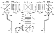
- FIG. 11 is a diagram showing a simplified form of an embodiment of the projector of the present invention.
- This light source device corresponds to R, G, B3 primary colors, an optical fiber bundle composed of a plurality of optical fibers of each color, that is, an optical fiber bundle (Efr) for an R color light source, an optical fiber bundle (Efg) for a G color light source. ),
- Each of the optical fiber bundles (Efb) for the B color light source is configured by bundling with the incident ends of the respective optical fibers aligned.
- Each of these luminous fluxes is reflected by a mirror (Hur, Hug, Hub), respectively, and the vertex arrangement is aperiodic two-dimensional lens array (Larr) and G-color two-dimensional lens array (Larg), B It passes through the color two-dimensional lens array (Larb) and becomes diffused light, and the front fly-eye lens (F1r, F1g, F1b), the rear fly-eye lens (F2r, F2g, F2b), and the polarization alignment function element (Pcr, Pcg) , Pcb) and illumination lenses (Ejr, Ejg, Ejb), and is incident on light uniformizing means (Fmr, Fmg, Fmb) by the fly eye integrator.
- the front fly-eye lens F1r, F1g, F1b
- the rear fly-eye lens F2r, F2g, F2b
- the polarization alignment function element Pcr, Pcg
- illumination lenses Ejr, Ejg, E
- the matching light emission region (Gf) is formed on the exit side surface of the two-dimensional lens array, and the incident end of the light uniformizing means (Fmr, Fmg, Fmb) is used.
- the light uniformizing means (Fmr, Fmg, Fmb) is arranged so as to be close to the surface on the emission side of the two-dimensional lens array.
- an R color image LCD (Dmr), a G color image LCD (Dmg), and a B color image, which are two-dimensional light amplitude modulation elements, are obtained by the respective light beams emitted from the light uniformizing means (Fmr, Fmg, Fmb).
- the LCD (Dmb) is illuminated, and the transmitted light beam is synthesized by the dichroic prism (Mj) into three colors to become a light beam (Fo) constituting a color image. This light beam is projected onto the screen by a projection lens (not shown).
- the polarization alignment function elements (Pcr, Pcg, Pcb) as shown in the figure are present, the polarization alignment function elements (Pcr, The maximum angle of light rays that can pass through (Pcg, Pcb) is not an axis subject, and is, for example, large in a direction parallel to the paper surface and small in a direction perpendicular to the paper surface.
- the two-dimensional lens array for R color (Larr), the two-dimensional lens array for G color (Larg), and the two-dimensional lens array for B color (Larb) have a non-axial directional distribution of diffused light as described above. It is preferable that the light beam is diffused so as not to exceed the maximum angle of the light beam in each direction. Note that speckle is conspicuous in R, G, and B colors due to human visibility, for example, it stands out in G color but not in B color. Therefore, the diffusivities of the R color two-dimensional lens array (Larr), the G color two-dimensional lens array (Larg), and the B color two-dimensional lens array (Labb) are adjusted according to the conspicuousness of each color. Adjust separately.
- the mirrors efficiently reflect the R color output light beam (Fr), the G color output light beam (Fg), and the B color output light beam (Fb) incident thereon. Created as However, there are not a few transmitted lights that are not reflected. Normally, these lights are discarded as stray light. However, in the present light source device shown in the figure, this light is used effectively to measure light beams (Fr ′, Fg ′, Fb ′). ).
- the measurement luminous fluxes (Fr ′, Fg ′, Fb ′) are incident on the R color sensor (Ar), the G color sensor (Ag), and the B color sensor (Ab), respectively, and the amount of light is measured. Used for light quantity stabilization feedback.
- FIG. 12 is a simplified diagram showing an embodiment of the projector according to the present invention, a specification using the two-dimensional lens array and the light deflecting means in combination as a form for carrying out the present invention.
- the configuration of the projector of the present invention using the light source device of the present invention as a white light source with enhanced light reduction will be described.
- a diverging light emitting portion existing on the surface of the semiconductor chip is used as a light emitting region (GsR, GsG, and GsB), and these are collimator lenses (EsR).
- EsG, EsB the light beam converted into an infinite image is color-combined using a mirror (HuR) and a dichroic mirror (HuG, HuB), and input to the imaging lens (Eu1). .
- this arrangement is such that the light emission regions (GsR, GsG, GsB) of R, G, and B colors are macroscopically overlapped (microscopically). As a single image, it looks like a white light source as a whole.
- the imaging lens (Eu1) forms a second light emission region (Gu) on the deflection mirror (Mdm) as a conjugate image with respect to the light emission region (GsR, GsG, GsB).
- the semiconductor laser light source unit (LsR, LsG, LsB) uses a plurality of semiconductor lasers as light sources, here, all chief rays from the light emitting region (Gs) are parallel to the optical axis. However, even if they are not parallel, an optical system having the same function can be realized by designing by controlling the position of the image plane and the pupil position on the optical axis.
- the deflection mirror (Mdm) is, for example, circular and is attached to the rotation shaft of a mirror rotation motor (Mdd) and rotated.
- the normal vector of the reflection surface of the deflection mirror (Mdm) is It is attached so as to be inclined at a predetermined angle. With this structure, the locus of the normal vector oscillates so as to draw a conical surface as the mirror rotation motor (Mdd) rotates, so that the deflection mirror (Mdm) rotates and oscillates. It becomes a mirror and functions as a light deflection means (Md).
- the light beam (Bd) deflected by the light deflecting means (Md) is incident on the second optical system (Ef) including the lenses (Ef11, Ef12) and the final lens (Ef13), and the second optical system ( Ef) is a conjugate image with respect to the second light emitting region (Gu) on the deflecting mirror (Mdm) on the incident-side surface of the two-dimensional lens array (Lar) whose apex is aperiodic.
- a three-light emission region (Gf ′) is imaged.
- the matching light emission region (Gf) is formed on the exit side surface of the two-dimensional lens array (Lar), and the light mixing means (Fm) composed of the light guide described above.
- the light mixing means (Fm) is arranged so that the incident end (Pmi) is close to the exit side surface of the two-dimensional lens array (Lar).
- the second light emission region (Gu) formed by the light beam (Bu) output from the optical system preceding the light deflection means (Md) is the deflection operation of the light deflection means (Md). Regardless of immobility. Moreover, since the second light emitting region (Gu) is in the vicinity of the deflection point of the light deflecting means (Md), the light emitting region as the starting point of the light beam (Bd) deflected by the light deflecting means (Md). Is almost immobile. And since the second light emitting region (Gu) and the third light emitting region (Gf ′) are conjugate, the third light emitting region (Gf ′) also remains almost stationary. Even if the deflection operation of the light deflecting means (Md) is performed, the state where the light beam (Bf) is incident on the incident end (Pmi) of the light mixing means (Fm) is always maintained.
- the optical design is such that the principal rays are substantially parallel to each other after passing through the second optical system (Ef).
- the light mixing means (Fm) comprising a light guide
- the input-side focal point of the second optical system (Ef) and the entrance pupil of the second optical system (Ef) coincide with each other.
- the entrance pupil (Qf3) is a conjugate image of the exit pupil (Qu) of the collimator lens (Es) based on the case where the deflection angle of the deflection mirror (Mdm) is zero.
- the light source device of this figure can maximize the maximum value of the deflection angle that can be given to the light deflection means (Md).
- the light deflection means (Md) continues the operation of continuously changing the direction in which the light beam (Bu) is deflected, thereby mixing the angle and position components of the incident light beam to the incident end (Pmi). Since the state changes continuously, the speckle always moves in the light beam (Bmo) emitted from the emission end (Pmo) of the light mixing means (Fm). When averaged within a suitable period, the speckled granular / spotted pattern becomes finer, and the speckles appear to disappear in synergy with the effect of being difficult to see.
- a projector that generates a color image can be configured by combining an image for each of R, G, and B colors generated by performing two-dimensional spatial modulation by the modulation element (DmjA) using a dichroic prism or the like.
- the light emission region (Gs) and the light emission region (GsR, GsG, GsB) in the light source device shown in FIGS. 10 and 12 have been formed by the semiconductor laser light source unit. These can be replaced with the light emission region (Gs) formed by the exit end of the optical fiber or optical fiber bundle.
- the present invention can be used in an industry for designing and manufacturing a light source device using a coherent light source such as a semiconductor laser that can be used in an optical device such as a projector.
- a coherent light source such as a semiconductor laser that can be used in an optical device such as a projector.
Abstract
スペックル低減用の2次元レンズアレイや交叉シリンドリカルレンズアレイの透過光に重畳される周期的模様の出現を回避すること。 コヒーレント光源(Sc)によって形成される光放射領域(Gs)と、入射端(Pmi)からの入射光線の角度と位置の成分の混合を行って射出端(Pmo)から射出する光混合手段(Fm)と、光放射領域(Gs)から発した光束を入射端(Pmi)に投影するための光束整合光学系(Eu)と、を有する光源装置であって、光束整合光学系(Eu)は、光拡散手段として機能する2次元レンズアレイ(Lar)を具備しており、2次元レンズアレイ(Lar)は、その有効領域が、少なくとも1個のサブ領域から構成され、サブ領域を構成する個々のレンズの頂点の並びが、非周期的である。
Description
本発明は、例えば、プロジェクタなどの光学装置において使用可能な、半導体レーザなどのコヒーレント光源を用いた光源装置に関する。
例えば、DLP(TM)プロジェクタや液晶プロジェクタのような画像表示用のプロジェクタや、フォトマスク露光装置においては、これまで、キセノンランプや超高圧水銀ランプなどの高輝度放電ランプ(HIDランプ)が使用されてきた。
一例として、本発明のプロジェクタに係わる従来のプロジェクタの一種の一部の一形態を説明する図である、図13を用いてプロジェクタの原理について述べる(参考:特開2004-252112号公報など)。
一例として、本発明のプロジェクタに係わる従来のプロジェクタの一種の一部の一形態を説明する図である、図13を用いてプロジェクタの原理について述べる(参考:特開2004-252112号公報など)。
前記したように、高輝度放電ランプ等からなる光源(SjA)からの光は、凹面反射鏡やレンズ等からなる集光手段(図示を省略)の助けを借りるなどして、光均一化手段(FmA)の入射端(PmiA)に入力され、射出端(PmoA)から出力される。
ここで、前記光均一化手段(FmA)として、例えば、光ガイドを使うことができ、これは、ロッドインテグレータ、ライトトンネルなどの名称でも呼ばれており、ガラスや樹脂などの光透過性の材料からなる角柱によって構成され、前記入射端(PmiA)に入力された光は、光ファイバと同じ原理に従って、前記光均一化手段(FmA)の側面で全反射を繰り返しながら、前記光均一化手段(FmA)の中を伝播することにより、仮に前記入射端(PmiA)に入力された光の分布にムラがあったとしても、前記射出端(PmoA)上の照度が十分に均一化されるように機能する。
ここで、前記光均一化手段(FmA)として、例えば、光ガイドを使うことができ、これは、ロッドインテグレータ、ライトトンネルなどの名称でも呼ばれており、ガラスや樹脂などの光透過性の材料からなる角柱によって構成され、前記入射端(PmiA)に入力された光は、光ファイバと同じ原理に従って、前記光均一化手段(FmA)の側面で全反射を繰り返しながら、前記光均一化手段(FmA)の中を伝播することにより、仮に前記入射端(PmiA)に入力された光の分布にムラがあったとしても、前記射出端(PmoA)上の照度が十分に均一化されるように機能する。
なお、いま述べた光ガイドに関しては、前記した、ガラスや樹脂などの光透過性の材料からなる角柱によって構成されるものの他に、中空の角筒で、その内面が反射鏡になっており、同様に内面で反射を繰り返しながら光を伝播させ、同様の機能を果たすものもある。
前記射出端(PmoA)の四角形の像が、2次元光振幅変調素子(DmjA)上に結像されるよう、照明レンズ(Ej1A)を配置することにより、前記射出端(PmoA)から出力された光によって前記2次元光振幅変調素子(DmjA)が照明される。 ただし、図13においては、前記照明レンズ(Ej1A)と前記2次元光振幅変調素子(DmjA)との間にミラー(MjA)を配置してある。
そして前記2次元光振幅変調素子(DmjA)は、映像信号に従って、画素毎に光を投影レンズ(Ej2A)に入射される方向に向かわせる、あるいは入射されない方向に向かわせるように変調することにより、スクリーン(Tj)上に画像を表示する。
そして前記2次元光振幅変調素子(DmjA)は、映像信号に従って、画素毎に光を投影レンズ(Ej2A)に入射される方向に向かわせる、あるいは入射されない方向に向かわせるように変調することにより、スクリーン(Tj)上に画像を表示する。
なお、前記したような2次元光振幅変調素子は、ライトバルブと呼ばれることもあり、図13の光学系の場合は、前記2次元光振幅変調素子(DmjA)として、一般にDMD(TM)(ディジタル・マイクロミラー・デバイス)が使われることが多い。
光均一化手段に関しては、前記した光ガイドの他に、フライアイインテグレータという名称で呼ばれるものもあり、この光均一化手段を使ったプロジェクタについて、一例として、本発明のプロジェクタに係わる従来のプロジェクタの一種の一部の一形態を説明する図である、図14を用いてその原理を述べる(参考:特開2001-142141号公報など)。
高輝度放電ランプ等からなる光源(SjB)からの光は、凹面反射鏡やレンズ等からなるコリメータ手段(図示を省略)の助けを借りるなどして、略平行光束として、フライアイインテグレータによる光均一化手段(FmB)の入射端(PmiB)に入力され、射出端(PmoB)から出力される。
ここで、前記光均一化手段(FmB)は、入射側の前段フライアイレンズ(F1B)と射出側の後段フライアイレンズ(F2B)と照明レンズ(Ej1B)の組合せで構成される。 前記前段フライアイレンズ(F1B)、前記後段フライアイレンズ(F2B)ともに、同一焦点距離、同一形状の四角形のレンズを、縦横それぞれに多数並べたものとして形成されている。
ここで、前記光均一化手段(FmB)は、入射側の前段フライアイレンズ(F1B)と射出側の後段フライアイレンズ(F2B)と照明レンズ(Ej1B)の組合せで構成される。 前記前段フライアイレンズ(F1B)、前記後段フライアイレンズ(F2B)ともに、同一焦点距離、同一形状の四角形のレンズを、縦横それぞれに多数並べたものとして形成されている。
前記前段フライアイレンズ(F1B)の各レンズと、それぞれの後段にある、前記後段フライアイレンズ(F2B)の対応するレンズとは、ケーラー照明と呼ばれる光学系を構成しており、したがって、ケーラー照明光学系が縦横に多数並んでいることになる。
一般にケーラー照明光学系とは、2枚のレンズから構成され、前段レンズが光を集めて対象面を照明するに際し、前段レンズは、対象面に光源像を結像するのではなく、後段レンズ中央の面上に光源像を結像し、後段レンズが前段レンズの外形の四角形を対象面(照明したい面)に結像するよう配置することにより、対象面を均一に照明するものである。
後段レンズの働きは、もしこれが無い場合は、光源が完全な点光源でなく有限の大きさを持つとき、その大きさに依存して対象面の四角形の周囲部の照度が落ちる現象を防ぐためで、後段レンズによって、光源の大きさに依存せずに、対象面の四角形の周囲部まで均一な照度にすることができる。
一般にケーラー照明光学系とは、2枚のレンズから構成され、前段レンズが光を集めて対象面を照明するに際し、前段レンズは、対象面に光源像を結像するのではなく、後段レンズ中央の面上に光源像を結像し、後段レンズが前段レンズの外形の四角形を対象面(照明したい面)に結像するよう配置することにより、対象面を均一に照明するものである。
後段レンズの働きは、もしこれが無い場合は、光源が完全な点光源でなく有限の大きさを持つとき、その大きさに依存して対象面の四角形の周囲部の照度が落ちる現象を防ぐためで、後段レンズによって、光源の大きさに依存せずに、対象面の四角形の周囲部まで均一な照度にすることができる。
ここで、図14の光学系の場合、前記光均一化手段(FmB)には略平行光束が入力されることを基本としているため、前記前段フライアイレンズ(F1B)と前記後段フライアイレンズ(F2B)との間隔は、それらの焦点距離に等しくなるように配置され、よってケーラー照明光学系としての均一照明の対象面の像は無限遠に生成される。
ただし、前記後段フライアイレンズ(F2B)の後段には、前記照明レンズ(Ej1B)を配置してあるため、対象面は、無限遠から前記照明レンズ(Ej1B)の焦点面上に引き寄せられる。
縦横に多数並んでいるケーラー照明光学系は、入射光軸(ZiB)に平行であり、それぞれの中心軸に対して略軸対称に光束が入力されるため、出力光束も略軸対称であるから、レンズ面に同じ角度で入射した光線は、レンズ面上の入射位置によらず、焦点面上の同じ点に向かうよう屈折される、というレンズの性質、即ちレンズのフーリエ変換作用により、全てのケーラー照明光学系の出力は、前記照明レンズ(Ej1B)の焦点面上の同じ対象面に結像される。
ただし、前記後段フライアイレンズ(F2B)の後段には、前記照明レンズ(Ej1B)を配置してあるため、対象面は、無限遠から前記照明レンズ(Ej1B)の焦点面上に引き寄せられる。
縦横に多数並んでいるケーラー照明光学系は、入射光軸(ZiB)に平行であり、それぞれの中心軸に対して略軸対称に光束が入力されるため、出力光束も略軸対称であるから、レンズ面に同じ角度で入射した光線は、レンズ面上の入射位置によらず、焦点面上の同じ点に向かうよう屈折される、というレンズの性質、即ちレンズのフーリエ変換作用により、全てのケーラー照明光学系の出力は、前記照明レンズ(Ej1B)の焦点面上の同じ対象面に結像される。
その結果、前記前段フライアイレンズ(F1B)の各レンズ面での照度分布が全て重ね合わされ、よって、ケーラー照明光学系が1個の場合よりも照度分布がより均一となった、1個の合成四角形の像が、前記入射光軸(ZiB)上に形成されることになる。
前記合成四角形の像の位置に2次元光振幅変調素子(DmjB)を配置することにより、前記射出端(PmoB)から出力された光によって、照明対象である前記2次元光振幅変調素子(DmjB)が照明される。
ただし、照明に際しては、前記照明レンズ(Ej1B)と前記2次元光振幅変調素子(DmjB)との間に偏光ビームスプリッタ(MjB)を配置して、これにより光が前記2次元光振幅変調素子(DmjB)に向けて反射されるようにしてある。
そして前記2次元光振幅変調素子(DmjB)は、映像信号に従って、画素毎に光の偏光方向を90度回転させる、あるいは回転させないように変調して反射することにより、回転させられた光のみが、前記偏光ビームスプリッタ(MjB)を透過して投影レンズ(Ej3B)に入射され、スクリーン(Tj)上に画像を表示する。
なお、図14の光学系の場合、前記2次元光振幅変調素子(DmjA)として、一般にLCOS(TM)(シリコン液晶デバイス)が使われることが多い。
このような液晶デバイスの場合、規定の偏光方向の光の成分しか有効に変調できないため、普通は、規定の偏光方向に平行な成分はそのまま透過させるが、規定の偏光方向に垂直な成分のみ偏光方向を90度回転させ、結果として全ての光を有効利用できるようにするための偏光整列機能素子(PcB)が、例えば前記後段フライアイレンズ(F2B)の後段に挿入される。
また、前記2次元光振幅変調素子(DmjB)には略平行光が入射されるよう、例えばその直前に、フィールドレンズ(Ej2B)が挿入される。
このような液晶デバイスの場合、規定の偏光方向の光の成分しか有効に変調できないため、普通は、規定の偏光方向に平行な成分はそのまま透過させるが、規定の偏光方向に垂直な成分のみ偏光方向を90度回転させ、結果として全ての光を有効利用できるようにするための偏光整列機能素子(PcB)が、例えば前記後段フライアイレンズ(F2B)の後段に挿入される。
また、前記2次元光振幅変調素子(DmjB)には略平行光が入射されるよう、例えばその直前に、フィールドレンズ(Ej2B)が挿入される。
なお、2次元光振幅変調素子に関しては、図14に記載したような反射型のものの他に、透過型の液晶デバイス(LCD)も、それに適合する光学配置にして使用される(参考:特開平10-133303号公報など)。
ところで、通常のプロジェクタでは、画像をカラー表示するために、例えば、前記光均一化手段の後段にカラーホイールなどの動的色フィルタを配置して、R,G,B(赤および緑、青)の色順次光束として前記2次元光振幅変調素子を照明し、時分割によってカラー表示を実現したり、あるいは、前記光均一化手段の後段にダイクロイックミラーやダイクロイックプリズムを配置してR,G,Bの3原色に色分解した光で各色独立に設けた2次元光振幅変調素子を照明し、ダイクロイックミラーやダイクロイックプリズムを配置してR,G,Bの3原色の変調光束の色合成を行うための光学系を構成するが、複雑になることを避けるため、図13、図14においては省略してある。
しかしながら、前記した高輝度放電ランプは、投入電力から光パワーへの変換効率が低い、すなわち発熱損が大きい、あるいは寿命が短い、などの欠点を有していた。
これらの欠点を克服した代替光源として、近年、LEDや半導体レーザ等の固体光源が注目されている。
このうち、LEDについては、放電ランプと比較して発熱損が小さく、また長寿命であるが、放射される光に関しては、放電ランプと同様に指向性が無いため、前記したプロジェクタや露光装置等の、特定の方向の光のみが利用可能な用途においては、光の利用効率が低いという問題があった。
これらの欠点を克服した代替光源として、近年、LEDや半導体レーザ等の固体光源が注目されている。
このうち、LEDについては、放電ランプと比較して発熱損が小さく、また長寿命であるが、放射される光に関しては、放電ランプと同様に指向性が無いため、前記したプロジェクタや露光装置等の、特定の方向の光のみが利用可能な用途においては、光の利用効率が低いという問題があった。
一方、半導体レーザについては、LEDと同様に、発熱損が小さく、長寿命である上に、指向性が高いため、前記したプロジェクタや露光装置等の、特定の方向の光のみが利用可能な用途においても、光の利用効率が高いという利点がある。
また、高い指向性を活かして、光ファイバによる光伝送を高効率で行えるため、半導体レーザの設置場所と、プロジェクタなど、その光を利用する場所とを分離することが可能であり、装置設計の自由度を高めることができる。
また、高い指向性を活かして、光ファイバによる光伝送を高効率で行えるため、半導体レーザの設置場所と、プロジェクタなど、その光を利用する場所とを分離することが可能であり、装置設計の自由度を高めることができる。
しかしその反面、半導体レーザにはスペックルノイズが発生するという問題があった。
ここでスペックルとは、半導体レーザやその他のレーザの光、あるいは(高調波発生・光パラメトリック効果などのような非線形光学現象を利用して)レーザ光を波長変換するなどして生成した、コヒーレント光を投射した場合に不可避的に現れる、粒状・斑点状の模様であって、前記したプロジェクタのような鑑賞用の映像を生成する用途や、感光性材料からなる被膜にフォトマスクのパターンを精密に露光する用途においては、画質を著しく劣化させる、非常に厄介な現象であるため、改善のための工夫が、古くから数多く提案されて来た。
ここでスペックルとは、半導体レーザやその他のレーザの光、あるいは(高調波発生・光パラメトリック効果などのような非線形光学現象を利用して)レーザ光を波長変換するなどして生成した、コヒーレント光を投射した場合に不可避的に現れる、粒状・斑点状の模様であって、前記したプロジェクタのような鑑賞用の映像を生成する用途や、感光性材料からなる被膜にフォトマスクのパターンを精密に露光する用途においては、画質を著しく劣化させる、非常に厄介な現象であるため、改善のための工夫が、古くから数多く提案されて来た。
例を挙げれば、拡散板・フライアイインテグレータ・ロッドインテグレータ・レンズアレイ・ビームスプリッタ・多重反射素子等を用いて、光軸に垂直な断面内で光束を分割して重ね合わせたり、光束の光軸に垂直な断面の位置に依存した位相・偏光状態・遅延等を付与したり、さらに光学素子を回転・振動・揺動するなどして分割状態や付与状態を時間的に変化させるなどである。
これらの工夫のうち、最も多用される手段が拡散板を用いるものであるが、この手段を単独で使う場合、その拡散度合いを強くするほど、これによってスペックルノイズ低減能力が高まる半面、光の利用効率が低下する、トレードオフの関係が存在するため、拡散板単独の働きに頼ってスペックルノイズ低減を行うものは少なく、前記したように他の手段を併用するものがほとんどである。
これらの工夫のうち、最も多用される手段が拡散板を用いるものであるが、この手段を単独で使う場合、その拡散度合いを強くするほど、これによってスペックルノイズ低減能力が高まる半面、光の利用効率が低下する、トレードオフの関係が存在するため、拡散板単独の働きに頼ってスペックルノイズ低減を行うものは少なく、前記したように他の手段を併用するものがほとんどである。
例えば、特開昭51-064325号公報には、レーザを用いた文字パターン発生装置において、スペックルによる解像力の低下を防止するため、拡散板としてのスリガラス円板を回転する技術が記載されており、類似の技術を提案した公報が極めて多数存在する。
そもそも拡散板のスペックルノイズ低減能力が高い理由は、例えば、ビームスプリッタによる光束分割の場合では、ビームスプリッタの1回通過によって、光束が2個に分割されるだけであるが、拡散板の場合では、光束の光軸に垂直な断面内の各点において、連続無数の部分光束への分割が行われ、ランダム的要素を含んで偏向角度が付与されるからである。
分割された部分光束は、下流において直ちに重ね合わせられ、スペックルが細分化されるが、細分化が十分に行われて視認困難なほど細かいスペックルになることにより、スペックルノイズ低減がなされる。
本発明に係わる従来技術の概念を説明する模式図である図15の(a)に示すように、いま、入射平行光束(Li)を拡散板(Ed)に対して垂直に入射させた場合、その透過光線の角度分布は、元の入射平行光束(Li)の方向、すなわち光軸(z)を中心の対称軸として、その軸方向にピークを有し、その軸と成す角度(ψ)が増加するほど分布割合が減少するが、広い裾を有する例えばガウシアン分布のような、図15の(b)に示す分布(P(ψ))のような形状になる。
スペックルの本質は干渉縞であり、干渉縞は重ね合わせる光線の角度が大きいほど細かくなるため、拡散板のスペックルノイズ低減作用において、透過光の角度分布のピークである、中心の光軸(z)まわりの成分は役に立っておらず、中心から隔たった、分布割合がピークより低い、ある下限角度(ψ1)以上で、かつ上限角度(ψ2)以下の範囲の角度を有する光の成分(Ap)がスペックルノイズ低減作用を担っていることが判る。
ここで前記上限角度(ψ2)は、一般に光学系において、そのNAに依存して、光線がその内部を最後まで伝播して有効に出力されることが可能な角度の、固有の上限値である。
したがって、スペックルノイズ低減能力を高めるためには、中心軸回りの成分を減らして、前記した下限角度(ψ1)以上の成分の割合を増せばよく、そのためには、拡散板透過光線の角度分布を広くすればよい。
しかしそうすると、分布の裾に属する成分も増加して、前記上限角度(ψ2)を超える成分が増加し、この成分は有効利用できないため、光学系の光利用効率が低下してしまい、前記した拡散度合いを強くするほど、これによってスペックルノイズ低減能力が高まる半面、光の利用効率が低下する問題が発現する。
それに留まらず、迷光となってシステムに有害な光が増加する結果となる。
拡散板が潜在的に有するこの問題を回避するためには、スペックルノイズ低減作用を担わない中心軸回りの成分や、有効利用できない裾に属する成分を含まない透過光角度分布を有する、拡散板の代わりに使用できる光学素子を考えればよく、具体的には、2次元レンズアレイがこの目的で使用可能である。
例えば、特開昭55-088002号公報には、スペックルパターンを記録したものを拡散板として利用するために、スペックルを発生させる手段として、通常の拡散板を用いる代わりに、ハエノ目レンズ(フライアイレンズ、すなわち2次元レンズアレイ)や、レンチキュラシートのシリンドリカルレンズの母線方向を直交させたもの(すなわち交叉シリンドリカルレンズアレイ)が好適に使用可能であることが記載されている。
また、例えば、特開昭59-226317号公報には、半導体露光装置等におけるレーザ光を用いたインコヒーレント照明を実現するために、回転揺動ミラーによる走査とフライアイレンズ(すなわち2次元レンズアレイ)、レンチキュラレンズによって生成した2次光源像を、ロッドインテグレータ等で重ね合わせる技術が記載されている。
さらに、特開平8-233544号公報には、レーザ光源による共焦点光学系を利用した3次元形状計測装置において、光源のコヒーレンスが高いことに起因した干渉縞によるノイズを低減するため、コヒーレンスを下げる目的で、光拡散手段を挿入し、これを振動または回転させる技術が記載されている。
光拡散手段としては、例えば、スリガラス、表面が散乱構造であるもの、オパールガラスなどの体積散乱するもの、回折格子、端面が不揃いな光ファイバーアレイなど、通常の拡散素子の他に、マイクロレンズアレイ(すなわち2次元レンズアレイ)を用いるとしている。
光拡散手段としては、例えば、スリガラス、表面が散乱構造であるもの、オパールガラスなどの体積散乱するもの、回折格子、端面が不揃いな光ファイバーアレイなど、通常の拡散素子の他に、マイクロレンズアレイ(すなわち2次元レンズアレイ)を用いるとしている。
さらに、特開平11-014551号公報には、紫外レ-ザ光を用いてマスクのパタ-ンの欠陥検査装置において、レーザ光をマイクロアレイレンズまたはハエの目レンズ(すなわち2次元レンズアレイ)と回転位相板を通すことにより干渉性をなくす技術が記載されている。
さらに、特開2008-309827号公報には、プロジェクタ等の投射型画像表示装置において、ロッドインテグレータの直前に回転マイクロレンズアレイ(すなわち2次元レンズアレイ)を挿入し、スペックルノイズ低減を行う技術が記載されている。
さらに、特開2009-042372号公報には、プロジェクタにおいて、半導体レーザ等の光のスペックルを低減するために、マイクロレンズアレイ(すなわち2次元レンズアレイ)等による光の拡散強度分布が、中心軸に対して少なくとも両側に1つずつの凸部を有する光拡散部材上位置に中間画像を形成し、その透過光を投影する技術が記載されている。
文献によりマイクロレンズアレイ、フライアイレンズ、ハエの目レンズなどと呼ばれるものは、球面レンズを2次元平面状に多数並べたもので、並べ方については、本発明に係わる従来技術の概念を説明する模式図である図16に記載のように、正方形レンズを縦横に並べたり、あるいは前記前段フライアイレンズ(F1B)や後段フライアイレンズ(F2B)のように長方形レンズを縦横に並べたり、6角形のレンズを蜂の巣状に並べるなど、種々の方法があるが、以降、本発明においては、並べ方によらず、これらを全て2次元レンズアレイと呼ぶ。
また、レンチキュラレンズは、シリンドリカルレンズを多数並べたものであるが、ここでの使用方法は本来のレンチキュラの技術(立体表示や多重画像表示)とは無関係であるため、以降、本発明では、これをシリンドリカルレンズアレイと呼び、また、本発明に係わる従来技術の概念を説明する模式図である図17に記載のように、母線方向が異なる複数のシリンドリカルレンズアレイ(Lca1’,Lca2’)を重ねたものを交叉シリンドリカルレンズアレイと呼ぶ。
また、レンチキュラレンズは、シリンドリカルレンズを多数並べたものであるが、ここでの使用方法は本来のレンチキュラの技術(立体表示や多重画像表示)とは無関係であるため、以降、本発明では、これをシリンドリカルレンズアレイと呼び、また、本発明に係わる従来技術の概念を説明する模式図である図17に記載のように、母線方向が異なる複数のシリンドリカルレンズアレイ(Lca1’,Lca2’)を重ねたものを交叉シリンドリカルレンズアレイと呼ぶ。
ここで、前記した、拡散板では拡散度合いを強くするほど、これによってスペックルノイズ低減能力が高まる半面、光の利用効率が低下する問題が、2次元レンズアレイを拡散板の代わりに使用すると回避できる理由について、本発明の光源装置の技術に関連する概念の概略図である図1を用いて説明する。
図1の(a)は、図16に記載の2次元レンズアレイ(Lar’)に多数含まれる単位正方形のうちの、一つの単位正方形(S0)を取出して拡大したものであり、上段は屈折面(Hs)を正面から見た図であり、下段は側面図である。
図1の(a)は、図16に記載の2次元レンズアレイ(Lar’)に多数含まれる単位正方形のうちの、一つの単位正方形(S0)を取出して拡大したものであり、上段は屈折面(Hs)を正面から見た図であり、下段は側面図である。
前記屈折面(Hs)は球面であり、裏側の屈折面は基板面(Hb)とし、したがって平面であり、この面に垂直に、平行光束が入射される場合を考える。
前記屈折面(Hs)の頂点すなわち中心を通過する光線は角度が変化しないが、幾何光学の近軸理論の教えるところによると、頂点からのズレ半径(r)だけずれた位置に入射する光は、ズレ半径(r)に比例した角度だけ偏向を受ける。
偏向角の絶対値のみに注目すると、ある角度 ψ だけ偏向を受ける光の分布の割合(すなわち光線の本数) P は、その角度に対応するズレ半径(r)を有する円(C1)の円周長に比例するから、P は 2πr に比例する。
ただし、ズレ半径(r)が前記単位正方形(S0)の内接円(C0)の半径(R)(すなわち単位正方形(S0)の辺長の半分)よりも大きくなると、分断された円(C2)の長さになるため、全周に対するその 有効存在範囲角(θ) の割合を乗じると、結局、ズレ半径(r)の関数としての分布量(P)は、図1の(b)に記載のようになる。
なお、関数の具体的な形は下段の数式の通りである。ただし、ピークで1となるよう、比例係数 2π は落としてある。
前記したように、半径 r は偏向角 ψ に対応するから、図1の(b)のグラフの横軸を ψ と見て、図15の(b)のグラフと比較すると、図1では、スペックルノイズ低減作用において役に立たない軸まわりの成分は存在せず、また、光の利用効率を下げる分布の裾に対応する成分も存在しないため、2次元レンズアレイを拡散板の代わりに使用することにより、スペックルノイズ低減作用が高く、かつ低損失なスペックルノイズ低減素子として機能する可能性があることが判る。
ただし、図1と図15との比較に際しては、横軸のスケーリングが異なり、直接の比較ができないことに注意されたい。
直接比較可能なスケーリングをするためには、前記屈折面(Hs)の曲率半径および前記2次元レンズアレイ(Lar’)の材料の屈折率の具体的な値を用いて、幾何光学の近軸理論の教えに従って前記屈折面(Hs)のパワーを求め、これにズレ半径(r)の最大値√2・R を乗ずることにより、具体的な偏向角の最大値、すなわち最大偏向角 Ψ を計算することができる。
あるいは、図1の(a)に記載のように、ズレ半径(r)の最大値 √2・R に対応する位置での、屈折面の法線(n)が光軸(z)と成す角度(Φ)を求め、スネルの法則に従って最大偏向角 Ψ を計算してもよい。 これにより、ズレ半径(r)の最大値 √2・R と最大偏向角 Ψ との対応が確定し、スケーリングが可能となる。
以上、2次元レンズアレイに関して説明したが、図17に記載のような交叉シリンドリカルレンズアレイの場合も、上記と同様の議論が可能で、特に母線方向が直交する交叉シリンドリカルレンズアレイの場合は、前記シリンドリカルレンズアレイ(Lca1’,Lca2’)の間隔を小さくとれば、少なくとも近軸理論の範囲では、光学的機能が球面レンズから成る前記2次元レンズアレイ(Lar’)と全く等価である。
なお、図においては、描画の都合により、上下の両方のシリンドリカルレンズアレイとも、基板の上側の面にシリンドリカルレンズが形成されているように描いてあるが、上のシリンドリカルレンズアレイは、シリンドリカルレンズが形成された側の面を下側に向け、上下のシリンドリカルレンズが向かい合う配置とする方が、球面レンズから成る前記2次元レンズアレイ(Lar’)への近似度が向上する。
なお、図においては、描画の都合により、上下の両方のシリンドリカルレンズアレイとも、基板の上側の面にシリンドリカルレンズが形成されているように描いてあるが、上のシリンドリカルレンズアレイは、シリンドリカルレンズが形成された側の面を下側に向け、上下のシリンドリカルレンズが向かい合う配置とする方が、球面レンズから成る前記2次元レンズアレイ(Lar’)への近似度が向上する。
ところが、2次元レンズアレイや交叉シリンドリカルレンズアレイは、先述の理屈の上では優れたスペックルノイズ低減作用を発揮するはずであるが、これらの透過光を利用して前記したプロジェクタを構成し、画像をスクリーンに投影すると、縞模様や格子模様などの周期的模様が重畳されて見えるという別の問題が起きる。
本発明が解決しようとする課題は、スペックル低減用の2次元レンズアレイや交叉シリンドリカルレンズアレイの透過光に重畳される周期的模様の出現を回避した光源装置およびプロジェクタを提供することにある。
本発明が解決しようとする課題は、スペックル低減用の2次元レンズアレイや交叉シリンドリカルレンズアレイの透過光に重畳される周期的模様の出現を回避した光源装置およびプロジェクタを提供することにある。
本発明における第1の発明の光源装置は、コヒーレント光源(Sc)によって形成される光放射領域(Gs)と、入射端(Pmi)からの入射光線の角度と位置の成分の混合を行って射出端(Pmo)から射出する光混合手段(Fm)と、前記光放射領域(Gs)から発した光束を前記入射端(Pmi)に投影するための光束整合光学系(Eu)と、を有する光源装置であって、前記光束整合光学系(Eu)は、光拡散手段として機能する2次元レンズアレイ(Lar)を具備しており、該2次元レンズアレイ(Lar)は、その有効領域が、少なくとも1個のサブ領域(A1,A2,…)から構成され、前記サブ領域を構成する個々のレンズ(L1,L2,…)の頂点(Lo1,Lo2,…)の並びが、非周期的であることを特徴とするものである。
本発明における第2の発明の光源装置は、前記サブ領域(A1,A2,…)におけるレンズ(L1,L2,…)の頂点(Lo1,Lo2,…)の並びは、周期的な並び方に基づく基本位置(Oxy)に対し、縦方向および横方向に、正負の位置ズレ(δx,δy)を有しており、該位置ズレ(δx,δy)の量が前記レンズ(L1,L2,…)毎に決められていることを特徴とするものである。
本発明における第3の発明の光源装置は、前記サブ領域(A1,A2,…)を構成する個々のレンズ(L1,L2,…)の頂点(Lo1,Lo2,…)の並びが、ランダム的であることを特徴とするものである。
本発明における第4の発明の光源装置は、前記サブ領域(A1,A2,…)を構成する個々のレンズ(L1,L2,…)は、並び方向が異なるシリンドリカルレンズアレイ(Lca1,Lca2)の複数枚を重ねることによって形成されており、前記シリンドリカルレンズアレイ(Lca1,Lca2)を構成する個々のシリンドリカルレンズ(Lc1,Lc2,…)は、その母線(Lx1,Lx2,…)の傾き角度(θ1,θ2,…)が、シリンドリカルレンズ毎に決められていることを特徴とするものである。
本発明における第5の発明の光源装置は、前記サブ領域(A1,A2,…)を構成する個々のレンズ(L1,L2,…)は、並び方向が異なるシリンドリカルレンズアレイ(Lca1,Lca2)の複数枚を重ねることによって形成されており、前記シリンドリカルレンズアレイ(Lca1,Lca2)を構成する個々のシリンドリカルレンズ(Lc1,Lc2,Lc3,…)は、その母線(Lx1,Lx2,Lx3,…)の並びにおける隣接するものとの母線間隔(d1,d2,…)が不均等であることを特徴とするものである。
本発明における第6の発明の光源装置は、前記光混合手段(Fm)は、所定空間に光を閉じ込めて光を多重反射させながら導波する光ガイドであることを特徴とするものである。
本発明における第7の発明の光源装置は、前記光混合手段(Fm)は、フライアイインテグレータであることを特徴とするものである。
本発明における第8の発明のプロジェクタは、第1から7の発明に記載の光源装置を利用して画像を投影表示するプロジェクタであって、光均一化手段が前記光混合手段(Fm)を兼ねるものである。
スペックル低減用の2次元レンズアレイや交叉シリンドリカルレンズアレイの透過光に重畳される周期的模様の出現を回避した光源装置およびプロジェクタを提供することができる。
従来技術における2次元レンズアレイや交叉シリンドリカルレンズアレイの透過光に前記した周期的模様が現れる第1の原因は、2次元レンズアレイや交叉シリンドリカルレンズアレイが周期的構造を有している事である。
周期的構造によって屈折・回折・散乱された光束は、周期的位相変調を受けるから、光学系の下流において重ね合わされたとき、干渉によって周期的模様が現れ、重畳されることになる。
そして第2の原因は、2次元レンズアレイを構成するレンズと隣接するレンズとの境界、もしくは交叉シリンドリカルレンズアレイを構成するシリンドリカルレンズと隣接するシリンドリカルレンズとの境界が、本来はV字状の鋭い切れ込みでなければならないものが、実際には、微視的にはU字状に鈍った形状になってしまい、素通しに近いシート状の光束が透過光に混入する事である。
なお第2の原因については、第1の原因による本質的問題を悪化させる要因であると言うこともできる。
先ず、本発明の光源装置を簡略化して示すブロック図である図2を用いて、本発明を実施するための形態について説明する。
本図において、例えばコヒーレント光源(Sc)が、半導体レーザである場合、その半導体レーザパッケージの内部に収納された、半導体チップの表面に存在する発散光の放射部は、実質的に点光源として扱うことができ、これを光放射領域(Gs)とすることができる。
本図において、例えばコヒーレント光源(Sc)が、半導体レーザである場合、その半導体レーザパッケージの内部に収納された、半導体チップの表面に存在する発散光の放射部は、実質的に点光源として扱うことができ、これを光放射領域(Gs)とすることができる。
レンズ等からなる光束整合光学系(Eu)は、前記光放射領域(Gs)からの光束(Bs)の入力を受けて、前記光放射領域(Gs)に対する投影領域として、後段の光混合手段(Fm)の入射端(Pmi)の近傍に、整合光放射領域(Gf)を形成する光束(Bf)を出力する。
ただし、前記光束整合光学系(Eu)には、その内部または前段あるいは後段に、後述する2次元レンズアレイ(Lar)が設置され、それへの入射光束に対し、光束の光軸に垂直な断面内の各点において、連続無数の部分光束への分割が行われ、非周期的要素を含んで偏向角度が付与された拡散光に変換する。
ただし、前記光束整合光学系(Eu)には、その内部または前段あるいは後段に、後述する2次元レンズアレイ(Lar)が設置され、それへの入射光束に対し、光束の光軸に垂直な断面内の各点において、連続無数の部分光束への分割が行われ、非周期的要素を含んで偏向角度が付与された拡散光に変換する。
そして、前記光混合手段(Fm)は、前記入射端(Pmi)より、前記光束整合光学系(Eu)からの前記光束(Bf)を入力され、前記光混合手段(Fm)の内部で入射光線の角度と位置の成分の混合が行われ、その射出端(Pmo)より光束(Bmo)が出力される。 出力された前記光束(Bmo)には、入射光線の角度と位置の成分の混合によって多重の干渉が生じせしめられる結果、それが投射された被照明面のスペックルの粒状・斑点状の模様が細かくなり、視認し難くなるという性質が付与される。
ただし、本発明の光源装置の一部の一例を簡略化して示す模式図である図3に示すように、前記2次元レンズアレイ(Lar)は、レンズが並んでいる有効領域が、少なくとも1個のサブ領域(A1,A2,…)から構成されており、一例として4個のサブ領域から構成されるものを図示してある。
そして、前記サブ領域のそれぞれの中では、それを構成する個々のレンズ(L1,L2,…)の頂点(Lo1,Lo2,…)の並びが、非周期的になるようにしてある。
そして、前記サブ領域のそれぞれの中では、それを構成する個々のレンズ(L1,L2,…)の頂点(Lo1,Lo2,…)の並びが、非周期的になるようにしてある。
ここで、本発明においては、前記頂点(Lo1,Lo2,…)とは、基板面に垂直に入射される光線が偏向されることなく射出される前記レンズ(L1,L2,…)における位置を指す。
したがって前記レンズ(L1,L2,…)が通常の球面レンズである場合、前記頂点(Lo1,Lo2,…)は、各レンズの屈折面の形状的頂点と一致する。
なお、ここで言う基板面とは、図1の(a)に記載の前記基板面(Hb)のように、前記2次元レンズアレイ(Lar)や、後述するシリンドリカルレンズアレイ(Lca1,Lca2)を構成する全体的基盤である基板によって規定される面である。
したがって前記レンズ(L1,L2,…)が通常の球面レンズである場合、前記頂点(Lo1,Lo2,…)は、各レンズの屈折面の形状的頂点と一致する。
なお、ここで言う基板面とは、図1の(a)に記載の前記基板面(Hb)のように、前記2次元レンズアレイ(Lar)や、後述するシリンドリカルレンズアレイ(Lca1,Lca2)を構成する全体的基盤である基板によって規定される面である。
図のなかの右側のものは、左側に描いた前記2次元レンズアレイ(Lar)のサブ領域の一部を拡大したものである。
線分で表したレンズ境界(Lb)に囲まれた多角形領域が個々のレンズを表す。
本図は、前記レンズ(L1,L2,…)が球面レンズである場合を想定して描かれているが、例えばホログラムレンズ等であってもよい。
このように、前記レンズ(L1,L2,…)の並び、特にその前記頂点(Lo1,Lo2,…)の並びを非周期的にしたことにより、従来技術における2次元レンズアレイや交叉シリンドリカルレンズアレイが周期的構造を有していることに起因して生じた、前記した縞模様や格子模様などの周期的模様が重畳されて見える問題を回避することができる。
線分で表したレンズ境界(Lb)に囲まれた多角形領域が個々のレンズを表す。
本図は、前記レンズ(L1,L2,…)が球面レンズである場合を想定して描かれているが、例えばホログラムレンズ等であってもよい。
このように、前記レンズ(L1,L2,…)の並び、特にその前記頂点(Lo1,Lo2,…)の並びを非周期的にしたことにより、従来技術における2次元レンズアレイや交叉シリンドリカルレンズアレイが周期的構造を有していることに起因して生じた、前記した縞模様や格子模様などの周期的模様が重畳されて見える問題を回避することができる。
なお、前記サブ領域について補足すると、例えば、サブ領域(A1,A2,A3,A4)の全部を合わせた領域を考えたときには、レンズの並びに周期性が現れても構わない。
具体的には、例えば前記サブ領域(A2,A3,A4)を、前記サブ領域(A1)のコピーによって構成することもできる。
何故ならば、このような構成の場合、周期性を有するとは言え、周期が非常に大きいため、干渉によって現れる周期的模様は細かくなり、実質的に視認不可能になるからである。
具体的には、例えば前記サブ領域(A2,A3,A4)を、前記サブ領域(A1)のコピーによって構成することもできる。
何故ならば、このような構成の場合、周期性を有するとは言え、周期が非常に大きいため、干渉によって現れる周期的模様は細かくなり、実質的に視認不可能になるからである。
その意味では、前記サブ領域の大きさを大きくして、前記2次元レンズアレイ(Lar)の有効領域全体を1個のサブ領域で構成することが、現れる周期的模様を細かくする上では理想的である。
ただしこの場合、前記2次元レンズアレイ(Lar)の製作が困難(高コスト)になる。
逆に、前記サブ領域を小さくすると、前記2次元レンズアレイ(Lar)の製作が容易(低コスト)になる利点がある反面、小さくし過ぎると、現れる周期的模様が粗くなって視認可能になってしまう。
ただし、周期的模様の見え方は、光学系の構造に依存する。
そのため、どの程度の大きさのサブ領域とするかは、具体的な光源装置の構造に基づいて、実験的に決めるのがよい。
なお、図3では、サブ領域(A1,A2,…)の形状が正方形であるものを例示したが、当然、長方形などでもよく、隣接するサブ領域どうしの間に著しい隙間が生じない限り、任意の形状を選ぶことができる。
先に、前記光放射領域(Gs)の例として、半導体チップの表面に存在する発散光の放射部を挙げたが、前記半導体レーザとしては、単一活性領域を有するものだけでなく、複数の活性領域が一列に並び、それぞれの活性領域から発散光が放射される半導体レーザアレイデバイスを用いることもできる。
あるいは、単一活性領域半導体レーザや半導体レーザアレイデバイスの複数個を備え、それらからの複数の発散光束を、レンズ系によって合成し、複数の点光源の集合体として前記光放射領域(Gs)を形成してもよく、本明細書では、これらを半導体レーザ光源ユニットと呼ぶ。
あるいは、単一活性領域半導体レーザや半導体レーザアレイデバイスの複数個を備え、それらからの複数の発散光束を、レンズ系によって合成し、複数の点光源の集合体として前記光放射領域(Gs)を形成してもよく、本明細書では、これらを半導体レーザ光源ユニットと呼ぶ。
また、いま述べたような、それ自身が発光体であるものだけでなく、例えば、入射端から半導体レーザや半導体レーザアレイデバイスの光が入力された光ファイバの射出端のコア像を前記光放射領域(Gs)とすることもできる。
さらに、そのような光ファイバの複数本を束ね、複数の射出端を密に配置した、光ファイババンドルの射出端を前記光放射領域(Gs)とすることもできる。
当然ながら本発明は、半導体レーザ以外にも、スペックルを生じ得る前記したようなコヒーレント光の発光体を光源とするもの全てに適用できる。
さらに、そのような光ファイバの複数本を束ね、複数の射出端を密に配置した、光ファイババンドルの射出端を前記光放射領域(Gs)とすることもできる。
当然ながら本発明は、半導体レーザ以外にも、スペックルを生じ得る前記したようなコヒーレント光の発光体を光源とするもの全てに適用できる。
次に、前記サブ領域(A1,A2,…)における前記レンズ(L1,L2,…)の前記頂点(Lo1,Lo2,…)を非周期的に並べるときの並べ方について説明する。
図3においては、従来技術によるもののような、周期的な頂点の並び方に基づく基本位置(Oxy)に対し、縦方向および横方向に、正負の位置ズレ(δx,δy)を有しており、該位置ズレ(δx,δy)の量が、それがどのレンズに属する頂点であるかに依存して変化するように構成する場合を描いてある。
図においては、周期的に頂点を並べる場合の基準線を縦横の一点鎖線で表し、それぞれの交点が前記基本位置(Oxy)であり、レンズの頂点の位置となる。
これに対し、レンズ毎の頂点に、前記位置ズレ(δx,δy)を与えた場合の頂点の位置を、丸の中に十字を描いたマークで表しており、それぞれが、それぞれ個別の仕方で一点鎖線の交点たる前記基本位置(Oxy)からずれていることが判る。
前記位置ズレ(δx,δy)の与え方については、例えば、前記2次元レンズアレイ(Lar)における縦横のレンズの並びを行列と見て、ある行のレンズのx方向の位置ズレ δx を左から順に見ると乱数配列を成し、同じ行のレンズのy方向の位置ズレ δy を左から順に見ると乱数配列を成し、他の行について見ても同様であり、また、ある列のレンズのx方向の位置ズレ δx を上から順に見ると乱数配列を成し、同じ列のレンズのy方向の位置ズレ δy を上から順に見ると乱数配列を成し、他の列について見ても同様であるように、すなわちランダムにすることができる。
あるいは、乱数配列に代えて、例えば、数学的な決定論的アルゴリズムに基づいて、非周期的な数値列を生成してもよい。
さらに、x方向の位置ズレ δx とy方向の位置ズレ δy とを要素とするベクトル (δx,δy) を考えたとき、このベクトルの大きさが全てのレンズで同じで、方向がレンズに依存して、例えばランダムに変化しているようにしてもよい。
あるいは、乱数配列に代えて、例えば、数学的な決定論的アルゴリズムに基づいて、非周期的な数値列を生成してもよい。
さらに、x方向の位置ズレ δx とy方向の位置ズレ δy とを要素とするベクトル (δx,δy) を考えたとき、このベクトルの大きさが全てのレンズで同じで、方向がレンズに依存して、例えばランダムに変化しているようにしてもよい。
さらに、本発明の光源装置の一部の一例を簡略化して示す模式図である図4に示すように、前記サブ領域(A1,A2,…)を構成する個々の前記レンズ(L1,L2,…)の前記頂点(Lo1,Lo2,…)の並びが、ランダム的であるように構成してもよい。
本図においても同様に、頂点の位置を、丸の中に十字を描いたマークで表してあり、また、線分で表したレンズ境界(Lb)に囲まれた多角形領域が個々のレンズを表す。
前記頂点(Lo1,Lo2,…)の並び方は、数学的に厳密な意味でランダムなものでもよいが、本発明においては、それに限らず、一見、ランダムのように見える(擬似ランダムな)ものでもよく、本図の並び方は、後者に相当する。
本図においても同様に、頂点の位置を、丸の中に十字を描いたマークで表してあり、また、線分で表したレンズ境界(Lb)に囲まれた多角形領域が個々のレンズを表す。
前記頂点(Lo1,Lo2,…)の並び方は、数学的に厳密な意味でランダムなものでもよいが、本発明においては、それに限らず、一見、ランダムのように見える(擬似ランダムな)ものでもよく、本図の並び方は、後者に相当する。
次に、前記した交叉シリンドリカルレンズアレイによる実現方法、すなわち前記サブ領域(A1,A2,…)を構成する個々のレンズ(L1,L2,…)を、並び方向が異なるシリンドリカルレンズアレイ(Lca1,Lca2)の複数枚を重ねることによって形成する場合について説明する。
本発明の光源装置の一部の一例を簡略化して示す模式図である図5に記載するように、前記シリンドリカルレンズアレイ(Lca1,Lca2)は2個あって、それぞれ延在方向(すなわち長辺の方向)が直交する2個の部分サブ領域(Ac11,Ac12)および部分サブ領域(Ac21,Ac22)を有する場合を描いてある。
それぞれの部分サブ領域においては、シリンドリカルレンズ(Lc1,Lc2,…)それぞれの母線の方向は、例えば部分サブ領域の短辺に平行(または略平行)であるとする。
図において矢印(t1,t2)で示すように、前記シリンドリカルレンズアレイ(Lca1,Lca2)は上下に重ね合わされ、2個ずつの前記部分サブ領域(Ac11,Ac12)と前記部分サブ領域(Ac21,Ac22)との組み合わせにより、図3の左に示したような形状の、計4個の前記サブ領域(A1,A2,A3,A4)が構成される。
したがって、前記サブ領域(A1,A2,A3,A4)それぞれにおいては、上下のシリンドリカルレンズアレイの母線の方向が直交(または略直交)するため、2次元レンズアレイと同等の光学的機能を有するものとなる。
当然ながら、前記シリンドリカルレンズアレイ(Lca1,Lca2)それぞれが、4個の部分サブ領域を有し、前記シリンドリカルレンズアレイ(Lca1,Lca2)を重ねたとき、それぞれの部分サブ領域が相対応して重なるように構成してもよい。
なお、2個のシリンドリカルレンズアレイを重ねるに際しては、前記したように上下のシリンドリカルレンズが向かい合う配置が望ましい。
また、ここでは一例として、2個のシリンドリカルレンズアレイを、その母線の方向が直交(または略直交)するように重ねたが、3個以上のシリンドリカルレンズアレイを重ねてもよく、また母線の方向が直角以外の角度をなすようにしてもよい。
(上の説明において、または略平行、または略直交と記載した理由は、後述する、1個の部分サブ領域に属する個々のシリンドリカルレンズの母線の方向が、互いに平行でないように構成する形態が存在するからである。)
なお、2個のシリンドリカルレンズアレイを重ねるに際しては、前記したように上下のシリンドリカルレンズが向かい合う配置が望ましい。
また、ここでは一例として、2個のシリンドリカルレンズアレイを、その母線の方向が直交(または略直交)するように重ねたが、3個以上のシリンドリカルレンズアレイを重ねてもよく、また母線の方向が直角以外の角度をなすようにしてもよい。
(上の説明において、または略平行、または略直交と記載した理由は、後述する、1個の部分サブ領域に属する個々のシリンドリカルレンズの母線の方向が、互いに平行でないように構成する形態が存在するからである。)
前記シリンドリカルレンズアレイ(Lca1,Lca2)を重ね合わせることによって形成されるサブ領域において、レンズの頂点の並びが非周期的になって、結果として前記シリンドリカルレンズアレイ(Lca1,Lca2)を重ね合わせたものが、一つの2次元レンズアレイ(Lar)として機能することを可能ならしめる、前記シリンドリカルレンズアレイ(Lca1,Lca2)の形態につき、以下において説明する。
前記シリンドリカルレンズアレイ(Lca1,Lca2)の一つの形態を、本発明の光源装置の一部の一例を簡略化して示す模式図である図6に示す。
本図のシリンドリカルレンズアレイ(Lca1)は、これを構成する個々のシリンドリカルレンズ(Lc1,Lc2,…)それぞれの母線(Lx1,Lx2,…)が、基準方向(y)に対して平行もしくは傾いており、その正負の傾き角度(θ1,θ2,…)が、シリンドリカルレンズ毎に与えられている。
前記傾き角度(θ1,θ2,…)の与え方については、例えば、前記シリンドリカルレンズを上から順に見て、それぞれの傾き角度を列挙すると乱数配列を成すように、すなわちランダムにすることができる。
あるいは、乱数配列に代えて、例えば、数学的な決定論的アルゴリズムに基づいて、非周期的な数値列を生成してもよい。
なお、図においては、シリンドリカルレンズの母線は一点鎖腺で表し、隣接するシリンドリカルレンズのレンズ境界(Lcb)は実線で表してある。
このようにして構成した2個のシリンドリカルレンズアレイ(Lca1,Lca2)を、前記したように上下に重ね合わせることによって形成されるサブ領域(A1,A2,…)の様子は、本発明の光源装置の一部の一例を簡略化して示す模式図である図7に記載のようになる。
図においては、上および下のシリンドリカルレンズアレイにおける、個々のシリンドリカルレンズのレンズ境界(Lcbx,Lcby)のサブ領域面への投影を実線で表し、また個々のシリンドリカルレンズの母線(Lx,Ly)のサブ領域面への投影を一点鎖腺で表してある。
前記した上および下のシリンドリカルレンズアレイの構成方法より明らかなように、縦および横方向の母線の交点(Lo)もまた、非周期的に並ぶことになる。
レンズ境界の実線で囲まれた4角形領域、および母線の交点(Lo)は、図3に記載した前記2次元レンズアレイ(Lar)においては、前記レンズ(L1,L2,…)、および頂点(Lo1,Lo2,…)に対応する。
したがって、前記のように構成した2個のシリンドリカルレンズアレイ(Lca1,Lca2)を、前記したように上下に重ね合わせることによって形成される交叉シリンドリカルレンズアレイにおいては、球面レンズの頂点の並びが非周期的になった2次元レンズアレイと等価な光学素子が実現できていることが判る。
なお、母線の交点(Lo)が頂点(Lo1,Lo2,…)に対応する理由は、前記したように、頂点とは、基板面に垂直に入射される光線が偏向されることなく射出されるレンズにおける位置を指すからである。
前記シリンドリカルレンズアレイ(Lca1,Lca2)の他の形態を、本発明の光源装置の一部の一例を簡略化して示す模式図である図8に示す。
本図のシリンドリカルレンズアレイ(Lca1,Lca2)は、これを構成する個々のシリンドリカルレンズ(Lc1,Lc2,Lc3,…)それぞれの母線(Lx1,Lx2,Lx3,…)の並びにおける隣接するものとの母線間隔(d1,d2,…)が不均等になるよう、シリンドリカルレンズの並び位置が決められている。
前記母線間隔(d1,d2,…)の決め方については、例えば、前記シリンドリカルレンズを上から順に見て、それぞれの母線間隔を列挙すると乱数配列を成すように、すなわちランダムにすることができる。
あるいは、乱数配列に代えて、例えば、数学的な決定論的アルゴリズムに基づいて、非周期的な数値列を生成してもよい。
なお、図においては、シリンドリカルレンズの母線は一点鎖腺で表し、隣接するシリンドリカルレンズのレンズ境界(Lcb)は実線で表してある。
このようにして構成した2個のシリンドリカルレンズアレイ(Lca1,Lca2)を、前記したように上下に重ね合わせることによって形成されるサブ領域(A1,A2,…)の様子は、本発明の光源装置の一部の一例を簡略化して示す模式図である図9に記載のようになる。
図においては、上および下のシリンドリカルレンズアレイにおける、個々のシリンドリカルレンズのレンズ境界(Lcbx,Lcby)のサブ領域面への投影を実線で表し、また個々のシリンドリカルレンズの母線(Lx,Ly)のサブ領域面への投影を一点鎖腺で表してある。
前記した上および下のシリンドリカルレンズアレイの構成方法より明らかなように、縦および横方向の母線の交点(Lo)もまた、非周期的に並ぶことになる。
レンズ境界の実線で囲まれた4角形領域、および母線の交点(Lo)は、図3に記載した前記2次元レンズアレイ(Lar)においては、前記レンズ(L1,L2,…)、および頂点(Lo1,Lo2,…)に対応する。
したがって、前記のように構成した2個のシリンドリカルレンズアレイ(Lca1,Lca2)を、前記したように上下に重ね合わせることによって形成される交叉シリンドリカルレンズアレイにおいては、球面レンズの頂点の並びが非周期的になった2次元レンズアレイと等価な光学素子が実現できていることが判る。
交叉シリンドリカルレンズアレイにより一つの2次元レンズアレイ(Lar)を構成することの利点の一つは、上および下のシリンドリカルレンズアレイの最大偏向角を相違させることにより、拡散光の方向分布が非軸対称となるような拡散板を実現することが容易にできることである。
例えば、z軸を光軸として、x軸方向には拡散が強く、y軸方向には拡散が弱い拡散板を作ることができる。
具体的には、拡散を強くしたい方のシリンドリカルレンズアレイの個々のシリンドリカルレンズについては、焦点距離を短くするか、焦点距離が同じなら母線間隔を全体的に長くすればよい。
当然ながら、上および下のシリンドリカルレンズアレイのうち、一方を図6の形態、他方を図8の形態によって構成してもよい。
また、上および下のシリンドリカルレンズアレイのうちの一方または両方を、図6の形態および図8の形態の両方の特徴を兼ね備えるように構成してもよい。
例えば、z軸を光軸として、x軸方向には拡散が強く、y軸方向には拡散が弱い拡散板を作ることができる。
具体的には、拡散を強くしたい方のシリンドリカルレンズアレイの個々のシリンドリカルレンズについては、焦点距離を短くするか、焦点距離が同じなら母線間隔を全体的に長くすればよい。
当然ながら、上および下のシリンドリカルレンズアレイのうち、一方を図6の形態、他方を図8の形態によって構成してもよい。
また、上および下のシリンドリカルレンズアレイのうちの一方または両方を、図6の形態および図8の形態の両方の特徴を兼ね備えるように構成してもよい。
以上において述べた前記2次元レンズアレイ(Lar)や前記シリンドリカルレンズアレイ(Lca1,Lca2)においては、頂点や母線の隣接するものどうしの間隔が不均等になるため、図1に記載した各レンズや各シリンドリカルレンズについての法線(n)の最大傾き角度(Φ)が不均等になる。
もし、この角度が過大なレンズがあると、偏向角が過大になり、効率が低下することになるため、前記角度(Φ)の上限値を決めておき、それを超えるレンズについては、頂点や母線の位置は変えずに、その曲率半径を補正して、過大な角度のものが出現しないようにすることができる。
もし、この角度が過大なレンズがあると、偏向角が過大になり、効率が低下することになるため、前記角度(Φ)の上限値を決めておき、それを超えるレンズについては、頂点や母線の位置は変えずに、その曲率半径を補正して、過大な角度のものが出現しないようにすることができる。
なお、図3および図4、図6、図8では、前記2次元レンズアレイ(Lar)や前記シリンドリカルレンズアレイ(Lca1,Lca2)の、個々のレンズの頂点や母線の位置に基づいて自然に決まる屈折面の交線によって、隣接するレンズとの境界線と成すように描いてあるが、境界線を、個々のレンズの頂点や母線の位置とは別に決めるようにしても構わない。
ところで、前記光混合手段(Fm)としては、それに光を入射したとき、入射光線の角度と位置の成分の混合が行われて射出されるものであれば、様々なものを使うことが可能である。
特に簡単なものとして、所定空間に光を閉じ込めて光を多重反射させながら導波する光ガイドを使うことができる。
特に簡単なものとして、所定空間に光を閉じ込めて光を多重反射させながら導波する光ガイドを使うことができる。
これは、先に図13に関して述べたように、ロッドインテグレータ、ライトトンネルなどの名称でも呼ばれており、ガラスや樹脂などの光透過性の材料からなる角柱によって構成され、前記入射端(Pmi)に入力された光は、光ファイバと同じ原理に従って、前記光混合手段(Fm)の側面で全反射を繰り返しながら、前記光混合手段(Fm)の中を伝播することにより、入射光線の角度と位置の成分の混合が行われる。
また、前記したように、いま述べた光ガイドに関しては、前記した、ガラスや樹脂などの光透過性の材料からなる角柱によって構成されるものの他に、中空の角筒で、その内面が反射鏡になっており、同様に内面で反射を繰り返しながら光を伝播させ、同様の機能を果たすものも使うことができる。
また、前記したように、いま述べた光ガイドに関しては、前記した、ガラスや樹脂などの光透過性の材料からなる角柱によって構成されるものの他に、中空の角筒で、その内面が反射鏡になっており、同様に内面で反射を繰り返しながら光を伝播させ、同様の機能を果たすものも使うことができる。
なお、このように所定空間に光を閉じ込めて光を多重反射させながら導波することにより、入射光線の角度と位置の成分の混合が行われる理由は、前記光混合手段(Fm)の全長に亘って多重反射を繰り返して光が伝播すると、もし前記射出端(Pmo)から覗いて見るならば、万華鏡の原理に従って、非常に多数の波源が見えるはずで、したがって、前記射出端(Pmo)には、非常に多数の波源からの光が到達し、射出して来る状態と等価となるからである。
また、さらに前記光混合手段(Fm)として、先に図14に関して述べたものと同様の、フライアイインテグレータを使うことができる。
フライアイインテグレータを使うことによって入射光線の角度と位置の成分の混合が行われる理由は、前記したように、フライアイインテグレータにおいては、入射側のフライアイレンズ上に縦横に並んだ、それぞれのレンズ外形の四角形の像が、全て1個に重ね合わせられるため、前記した光ガイドの場合と同様に、万華鏡のような状態が現出され、照明対象には、非常に多数の波源からの光が同時に到達することになるからである。
フライアイインテグレータを使うことによって入射光線の角度と位置の成分の混合が行われる理由は、前記したように、フライアイインテグレータにおいては、入射側のフライアイレンズ上に縦横に並んだ、それぞれのレンズ外形の四角形の像が、全て1個に重ね合わせられるため、前記した光ガイドの場合と同様に、万華鏡のような状態が現出され、照明対象には、非常に多数の波源からの光が同時に到達することになるからである。
なお、前記光混合手段(Fm)としてフライアイインテグレータを使う場合は、その入射端(Pmi)の近傍に形成される前記整合光放射領域(Gf)は、前記入射端(Pmi)の全領域に亘って拡がった照明領域として形成されることが望ましい。
その理由は、もし、前記整合光放射領域(Gf)が前記入射端(Pmi)のフライアイレンズの一部にしか入射されなければ、前記した、重ね合わせられるレンズ外形の四角形の像の枚数が減り、入射光線の角度と位置の成分の混合の作用が弱まるからである。
その理由は、もし、前記整合光放射領域(Gf)が前記入射端(Pmi)のフライアイレンズの一部にしか入射されなければ、前記した、重ね合わせられるレンズ外形の四角形の像の枚数が減り、入射光線の角度と位置の成分の混合の作用が弱まるからである。
一方、前記した、前記光混合手段(Fm)として光ガイドを使う場合においては、前記入射端(Pmi)の1箇所や複数箇所に集中する、例えば点像のような形態で光が入射されるものでも構わない。
その理由は、その点像の結像拡がり角が適当であれば、光束は光ガイドを伝播する間に拡がって、射出端(Pmo)に達すると、入射光線の角度と位置の成分の混合が十分に行われるからである。
その理由は、その点像の結像拡がり角が適当であれば、光束は光ガイドを伝播する間に拡がって、射出端(Pmo)に達すると、入射光線の角度と位置の成分の混合が十分に行われるからである。
前記したように、従来の高輝度放電ランプなど、何らかの光源を利用して画像を投影表示するプロジェクタにおいては、光ガイドやフライアイインテグレータなどの光均一化手段が必要不可欠の構成要素であるが、この光均一化手段は、前記したように、スペックルの粒状・斑点状の模様が細かくなり、視認し難くなるようにするために、本発明の構成要素である前記光混合手段(Fm)としても機能させることができる。
したがって、本発明の光源装置を光源として利用して画像を投影表示するプロジェクタを実現する際は、光均一化手段が前記光混合手段(Fm)を兼ねるように構成することで、コストダウンが可能となる。
したがって、本発明の光源装置を光源として利用して画像を投影表示するプロジェクタを実現する際は、光均一化手段が前記光混合手段(Fm)を兼ねるように構成することで、コストダウンが可能となる。
前記したように、従来のプロジェクタでは、画像をカラー表示するために、例えば、前記光均一化手段の後段にカラーホイールなどの動的色フィルタを配置して、R,G,B(赤および緑、青)の色順次光束として前記2次元光振幅変調素子を照明し、時分割によってカラー表示を実現したり、あるいは、前記光均一化手段の後段にダイクロイックミラーやダイクロイックプリズムを配置してR,G,Bの3原色に色分解した光で各色独立に設けた2次元光振幅変調素子を照明し、ダイクロイックミラーやダイクロイックプリズムを配置してR,G,Bの3原色の変調光束の色合成を行うための光学系を構成する。
本発明のプロジェクタにおいても、必要な種類の色相の光源を必要とするが、例えばR・G・Bの3原色のコヒーレント光源を用いて、それらを色合成した白色の光放射領域(Gs)を形成し、前記したように光束整合光学系(Eu)を経て、光均一化手段たる光混合手段(Fm)に白色光を入射して、従来のプロジェクタと同様に、前記光混合手段(Fm)よりも後段において、動的色フィルタによる時分割処理、または色分解と色合成を行うようにすることができる。
なお、前記した光ファイバを用いるものの場合、色合成した光放射領域(Gs)の形成に際して、入射端において異なる色の光が入射された複数の光ファイバの射出端部を束ねた光ファイババンドルを用いることにより、前記光放射領域(Gs)が複数色の部分からなるものとすることができるし、あるいは、色毎に単色の光放射領域(Gs)を形成しておき、それらをダイクロイックミラー等の色合成手段を用いて重ね合わせて光束整合光学系(Eu)に光を送ることにより、結果的に色合成した前記光放射領域(Gs)を形成することもできる。
なお、前記光束整合光学系(Eu)側から前記色合成手段側を見れば、複数色を有する1個の光放射領域(Gs)が見え、光学分野では、この状態を指して、色合成した光放射領域(Gs)が形成されていると見なす。
なお、前記光束整合光学系(Eu)側から前記色合成手段側を見れば、複数色を有する1個の光放射領域(Gs)が見え、光学分野では、この状態を指して、色合成した光放射領域(Gs)が形成されていると見なす。
あるいは、色毎に独立に光放射領域(Gs)の形成、光束整合光学系(Eu)、光均一化手段たる光混合手段(Fm)を経て、2次元光振幅変調素子を照明して単色画像を生成し、これを色合成するようにしてもよい。
あるいは、例えばR・G・Bの順に、時分割でコヒーレント光源を駆動することにより、色順次の光放射領域(Gs)を形成し、光束整合光学系(Eu)、光均一化手段たる光混合手段(Fm)を経て、2次元光振幅変調素子を照明することにより、色順次カラー画像を生成するようにしてもよい。
以下において、本発明を実施するための形態について説明する。
先ず、本発明の光源装置の実施例の一形態を簡略化して示す図である図10に記載の光源装置について説明する。
前記コヒーレント光源たる、1個または複数個の半導体レーザを光源とする半導体レーザ光源ユニット(Ls)における、半導体チップの表面に存在する発散光の放射部を光放射領域(Gs)とする。
該光放射領域(Gs)からの光束は、コリメータレンズ(Es)、および頂点並びが非周期的な2次元レンズアレイ(Lar)、結像レンズ(Eu0)からなる光束整合光学系(Eu)に入射される。
前記コリメータレンズ(Es)は前記光放射領域(Gs)を無限遠の像に変換するとともに、2次元レンズアレイを照明し、該2次元レンズアレイによって拡散光となった光束は、結像レンズ(Eu0)に入射され、前記2次元レンズアレイの被照明領域が、入力像として拡大されるとともに拡散角度が減じられて、整合光放射領域(Gf)を形成する。
前記した光ガイドよりなる入射端(Pmi)が、前記整合光放射領域(Gf)に概ね一致するよう光混合手段(Fm)を配置することにより、射出端(Pmo)より前記した周期的模様が目立たずスペックルが低減された光束(Bmo)を取出し、利用することができる。
次に、本発明のプロジェクタの実施例の一形態を簡略化して示す図である図11を用いて、本発明を実施するための形態として、本発明の光源装置を利用した、本発明のプロジェクタの、特に光ファイバおよびその射出端以降の、より具体的な構成について述べる。
本光源装置は、R,G,B3原色に対応する、各色複数本の光ファイバからなる光ファイババンドル、すなわちR色光源用の光ファイババンドル(Efr)、G色光源用の光ファイババンドル(Efg)、B色光源用の光ファイババンドル(Efb)それぞれは、それぞれの各光ファイバの入射端を揃えて束ねられて構成される。
これら3本の光ファイババンドルの出射端(Eor,Eog,Eob)の像を、それぞれコリメータレンズ(Esr,Esg,Esb)を用いて無限遠の像に変換することによって、R色出力光束(Fr)およびG色出力光束(Fg)、B色出力光束(Fb)を生成する。
本光源装置は、R,G,B3原色に対応する、各色複数本の光ファイバからなる光ファイババンドル、すなわちR色光源用の光ファイババンドル(Efr)、G色光源用の光ファイババンドル(Efg)、B色光源用の光ファイババンドル(Efb)それぞれは、それぞれの各光ファイバの入射端を揃えて束ねられて構成される。
これら3本の光ファイババンドルの出射端(Eor,Eog,Eob)の像を、それぞれコリメータレンズ(Esr,Esg,Esb)を用いて無限遠の像に変換することによって、R色出力光束(Fr)およびG色出力光束(Fg)、B色出力光束(Fb)を生成する。
これら各光束は、それぞれミラー(Hur,Hug,Hub)で反射されて、それぞれ頂点並びが非周期的なR色用2次元レンズアレイ(Larr)およびG色用2次元レンズアレイ(Larg)、B色用2次元レンズアレイ(Larb)を通過し、拡散光となって前段フライアイレンズ(F1r,F1g,F1b)および後段フライアイレンズ(F2r,F2g,F2b)、偏光整列機能素子(Pcr,Pcg,Pcb)、照明レンズ(Ejr,Ejg,Ejb)からなる、前記したフライアイインテグレータによる光均一化手段(Fmr,Fmg,Fmb)に入射される。
すなわち、本図の形態では、整合光放射領域(Gf)は、前記2次元レンズアレイの射出側の面上に形成されているとして、光均一化手段(Fmr,Fmg,Fmb)の入射端を、前記2次元レンズアレイの射出側の面に近接するよう前記光均一化手段(Fmr,Fmg,Fmb)を配置する。
すなわち、本図の形態では、整合光放射領域(Gf)は、前記2次元レンズアレイの射出側の面上に形成されているとして、光均一化手段(Fmr,Fmg,Fmb)の入射端を、前記2次元レンズアレイの射出側の面に近接するよう前記光均一化手段(Fmr,Fmg,Fmb)を配置する。
そして前記光均一化手段(Fmr,Fmg,Fmb)から出たそれぞれの光束によって、2次元光振幅変調素子たるR色画像用LCD(Dmr)およびG色画像用LCD(Dmg)、B色画像用LCD(Dmb)が照明され、その透過光束がダイクロイックプリズム(Mj)によって3色合成され、カラー画像を構成する光束(Fo)となる。
この光束は、投影レンズによってスクリーンに投影される(図示を省略)。
この光束は、投影レンズによってスクリーンに投影される(図示を省略)。
ところで、本図のような前記偏光整列機能素子(Pcr,Pcg,Pcb)が存在する、フライアイインテグレータによる前記光均一化手段(Fmr,Fmg,Fmb)の場合、前記偏光整列機能素子(Pcr,Pcg,Pcb)を通過できる光線の最大角度は軸対象ではなく、例えば紙面に平行な方向では大きく、紙面に垂直な方向では小さい。
そのため、前記R色用2次元レンズアレイ(Larr)および前記G色用2次元レンズアレイ(Larg)、前記B色用2次元レンズアレイ(Larb)は、前記した、拡散光の方向分布が非軸対称となるようにした交叉シリンドリカルレンズアレイにより構成し、各方向の光線の最大角度を超えないように光束を拡散させることが好適である。
なお、人間の視感度の関係で、スペックルの目立ち方はR色、G色、B色で相違し、例えば、G色では目立つがB色では目立たない。
そのため、色毎の目立ち方に合わせて前記R色用2次元レンズアレイ(Larr)および前記G色用2次元レンズアレイ(Larg)、前記B色用2次元レンズアレイ(Larb)それぞれの拡散度を別々に調整するとよい。
因みに、前記ミラー(Hur,Hug,Hub)は、それぞれに入射される前記R色出力光束(Fr)および前記G色出力光束(Fg)、前記B色出力光束(Fb)を効率的に反射するように作成される。
しかし、反射されない透過光が少なからず存在し、普通これらの光は迷光として捨てられるが、本図の本光源装置においては、これを有効利用して測定用光束(Fr’,Fg’,Fb’)を得るようにしてある。
そして前記測定用光束(Fr’,Fg’,Fb’)は、それぞれ前記R色センサ(Ar)および前記G色センサ(Ag)、前記B色センサ(Ab)に入射されて光量が測定され、光量安定化フィードバック等のために利用される。
しかし、反射されない透過光が少なからず存在し、普通これらの光は迷光として捨てられるが、本図の本光源装置においては、これを有効利用して測定用光束(Fr’,Fg’,Fb’)を得るようにしてある。
そして前記測定用光束(Fr’,Fg’,Fb’)は、それぞれ前記R色センサ(Ar)および前記G色センサ(Ag)、前記B色センサ(Ab)に入射されて光量が測定され、光量安定化フィードバック等のために利用される。
次に、本発明のプロジェクタの実施例の一形態を簡略化して示す図である図12を用いて、本発明を実施するための形態として、2次元レンズアレイと光偏向手段を併用してスペックル低減を強化した白色光源としての本発明の光源装置を構成し、それを利用した、本発明のプロジェクタの構成について述べる。
R・G・B各色の半導体レーザ光源ユニット(LsR,LsG,LsB)における半導体チップの表面に存在する発散光の放射部を光放射領域(GsR,GsG,GsB)とし、それらをコリメータレンズ(EsR,EsG,EsB)で無限遠の像に変換した光束を、ミラー(HuR)およびダイクロイックミラー(HuG,HuB)を用いて色合成し、結像レンズ(Eu1)に入力するように構成してある。
この配置は、逆に前記結像レンズ(Eu1)の側から見ると、R・G・B各色の前記光放射領域(GsR,GsG,GsB)が、巨視的には重なって(微視的に見れば重なっていないかも知れないが)1個の像として、全体として白色の光源に見える。
前記結像レンズ(Eu1)は、前記光放射領域(GsR,GsG,GsB)に対する共役な像として、偏向用ミラー(Mdm)の上に第2光放射領域(Gu)を結像させる。
この配置は、逆に前記結像レンズ(Eu1)の側から見ると、R・G・B各色の前記光放射領域(GsR,GsG,GsB)が、巨視的には重なって(微視的に見れば重なっていないかも知れないが)1個の像として、全体として白色の光源に見える。
前記結像レンズ(Eu1)は、前記光放射領域(GsR,GsG,GsB)に対する共役な像として、偏向用ミラー(Mdm)の上に第2光放射領域(Gu)を結像させる。
なお、前記半導体レーザ光源ユニット(LsR,LsG,LsB)が複数個の半導体レーザを光源とするものの場合、ここでは、前記光放射領域(Gs)からの全主光線が光軸に平行である場合を基本とするが、平行でない場合であっても、光軸上での像平面の位置、瞳位置を制御して設計することにより、同様の機能の光学系を実現することができる。
前記偏向用ミラー(Mdm)は、例えば円形で、ミラー回転モータ(Mdd)の回転軸に取り付けられて回転させられるが、前記偏向用ミラー(Mdm)の反射面の法線ベクトルが、回転軸に対して所定角度だけ傾くように取り付ける。
このような構造とすることにより、前記ミラー回転モータ(Mdd)の回転に伴い、前記法線ベクトルの軌跡は円錐面を描くように揺動するため、前記偏向用ミラー(Mdm)は回転揺動ミラーとなり、光偏向手段(Md)として機能する。
このような構造とすることにより、前記ミラー回転モータ(Mdd)の回転に伴い、前記法線ベクトルの軌跡は円錐面を描くように揺動するため、前記偏向用ミラー(Mdm)は回転揺動ミラーとなり、光偏向手段(Md)として機能する。
前記光偏向手段(Md)によって偏向された光束(Bd)は、レンズ(Ef11,Ef12)、および最終のレンズ(Ef13)からなる第2光学系(Ef)に入射され、該第2光学系(Ef)は、前記偏向用ミラー(Mdm)上の前記第2光放射領域(Gu)に対する共役な像として、頂点並びが非周期的な2次元レンズアレイ(Lar)の入射側の面上に第3光放射領域(Gf’)を結像させる。
そして本図の形態では、整合光放射領域(Gf)は、前記2次元レンズアレイ(Lar)の射出側の面上に形成されているとして、前記した光ガイドよりなる光混合手段(Fm)の入射端(Pmi)を、前記2次元レンズアレイ(Lar)の射出側の面に近接するよう前記光混合手段(Fm)を配置する。
そして本図の形態では、整合光放射領域(Gf)は、前記2次元レンズアレイ(Lar)の射出側の面上に形成されているとして、前記した光ガイドよりなる光混合手段(Fm)の入射端(Pmi)を、前記2次元レンズアレイ(Lar)の射出側の面に近接するよう前記光混合手段(Fm)を配置する。
ところで、前記光偏向手段(Md)より前段にある光学系から出力される光束(Bu)によって形成される前記第2光放射領域(Gu)は、前記光偏向手段(Md)の偏向動作とは無関係に不動のものである。
しかも、前記第2光放射領域(Gu)が前記光偏向手段(Md)の偏向点の近傍にあるため、前記光偏向手段(Md)によって偏向された前記光束(Bd)の起点たる光放射領域もほとんど不動になる。
そして、前記第2光放射領域(Gu)と前記第3光放射領域(Gf’)とは共役であることにより、前記第3光放射領域(Gf’)も、ほとんど不動のままになるため、前記光偏向手段(Md)の偏向動作が行われても、前記光束(Bf)は、前記光混合手段(Fm)の前記入射端(Pmi)に入射される状態が常に維持される。
しかも、前記第2光放射領域(Gu)が前記光偏向手段(Md)の偏向点の近傍にあるため、前記光偏向手段(Md)によって偏向された前記光束(Bd)の起点たる光放射領域もほとんど不動になる。
そして、前記第2光放射領域(Gu)と前記第3光放射領域(Gf’)とは共役であることにより、前記第3光放射領域(Gf’)も、ほとんど不動のままになるため、前記光偏向手段(Md)の偏向動作が行われても、前記光束(Bf)は、前記光混合手段(Fm)の前記入射端(Pmi)に入射される状態が常に維持される。
なお、前記第2光学系(Ef)を通過後においては、主光線が互いに略平行になるように光学設計することが好適である。
その理由は、光ガイドよりなる前記光混合手段(Fm)においても、その内部を損失無く伝播できる光線の最大角度が存在するため、主光線どうしが成す角度と、前記2次元レンズアレイ(Lar)が付与する拡散角と、前記偏向用ミラー(Mdm)が付与する偏向角との和を、前記最大角度以内に収める必要があるが、スペックル低減効果を最大限に発揮するためには、スペックル低減に寄与しない主光線どうしが成す角度を小さくし、前記2次元レンズアレイ(Lar)が付与する拡散角または前記偏向用ミラー(Mdm)が付与する偏向角を大きくすることが有利となるからである。
その理由は、光ガイドよりなる前記光混合手段(Fm)においても、その内部を損失無く伝播できる光線の最大角度が存在するため、主光線どうしが成す角度と、前記2次元レンズアレイ(Lar)が付与する拡散角と、前記偏向用ミラー(Mdm)が付与する偏向角との和を、前記最大角度以内に収める必要があるが、スペックル低減効果を最大限に発揮するためには、スペックル低減に寄与しない主光線どうしが成す角度を小さくし、前記2次元レンズアレイ(Lar)が付与する拡散角または前記偏向用ミラー(Mdm)が付与する偏向角を大きくすることが有利となるからである。
前記したように、出力光束の主光線が互いに略平行になる光学系は、前記第2光学系(Ef)の入力側焦点と前記第2光学系(Ef)の入射瞳とが一致するように設計することにより実現することができるが、これを本図に即して、もっと判り易く言うと、前記最終のレンズ(Ef13)に注目して、その入力側焦点と入射瞳(Qf3)とを一致させればよいことになる。
そして、該入射瞳(Qf3)は、前記偏向用ミラー(Mdm)の偏向角が零である場合を基本として、前記コリメータレンズ(Es)の射出瞳(Qu)の共役像であり、前記した前記光放射領域(Gs)からの全主光線が光軸に平行である場合を考えるなら、前記射出瞳(Qu)は、前記コリメータレンズ(Es)の出力側焦点に一致する。
以上のように構成したことにより、本図の光源装置は、前記光偏向手段(Md)に与えることのできる偏向角度の最大値を最大限にすることができる。
そして、該入射瞳(Qf3)は、前記偏向用ミラー(Mdm)の偏向角が零である場合を基本として、前記コリメータレンズ(Es)の射出瞳(Qu)の共役像であり、前記した前記光放射領域(Gs)からの全主光線が光軸に平行である場合を考えるなら、前記射出瞳(Qu)は、前記コリメータレンズ(Es)の出力側焦点に一致する。
以上のように構成したことにより、本図の光源装置は、前記光偏向手段(Md)に与えることのできる偏向角度の最大値を最大限にすることができる。
前記光偏向手段(Md)は、前記光束(Bu)を偏向する方向を連続的に変化させる動作を継続することにより、前記入射端(Pmi)への入射光線の角度と位置の成分の混合の状態が連続的に変化することになるため、前記光混合手段(Fm)の前記射出端(Pmo)から射出される前記光束(Bmo)においては、スペックルは常に移動するため、その移動速度に見合う適当な期間内で平均すると、前記したスペックルの粒状・斑点状の模様が細かくなり、視認し難くなる効果と相乗して、スペックルは消滅して見えることになる。
したがって射出端(Pmo)より前記した周期的模様が目立たずスペックルが低減された光束(Bmo)を出力させることができる。
前記光混合手段(Fm)の後段においては、前記光束(Bmo)をR,G,Bの色分解を行い、先に説明した図13の従来のプロジェクタと同様に、映像信号に従って2次元光振幅変調素子(DmjA)による2次元空間変調を行って生成されたR,G,Bの色毎の画像を、ダイクロイックプリズム等によって合成することにより、カラー画像を生成するプロジェクタを構成することができる。
前記光混合手段(Fm)の後段においては、前記光束(Bmo)をR,G,Bの色分解を行い、先に説明した図13の従来のプロジェクタと同様に、映像信号に従って2次元光振幅変調素子(DmjA)による2次元空間変調を行って生成されたR,G,Bの色毎の画像を、ダイクロイックプリズム等によって合成することにより、カラー画像を生成するプロジェクタを構成することができる。
これまでの説明においては、図10や図12に記載の光源装置における光放射領域(Gs)および光放射領域(GsR,GsG,GsB)については、半導体レーザ光源ユニットによって形成されるものとしてきたが、これらを、光ファイバや光ファイババンドルの射出端によって形成される光放射領域(Gs)に置き換えることが可能である。
本発明は、プロジェクタなどの光学装置において使用可能な、半導体レーザなどのコヒーレント光源を用いた光源装置を設計・製造する産業において利用可能である。
A1 サブ領域
A2 サブ領域
A3 サブ領域
A4 サブ領域
Ab B色センサ
Ac11 部分サブ領域
Ac12 部分サブ領域
Ac21 部分サブ領域
Ac22 部分サブ領域
Ag G色センサ
Ap 成分
Ar R色センサ
Bd 光束
Bf 光束
Bmo 光束
Bs 光束
Bu 光束
C0 内接円
C1 円
C2 円
d1 母線間隔
d2 母線間隔
Dmb B色画像用LCD
Dmg G色画像用LCD
DmjA 2次元光振幅変調素子
DmjB 2次元光振幅変調素子
Dmr R色画像用LCD
Ed 拡散板
Ef 第2光学系
Ef11 レンズ
Ef12 レンズ
Ef13 レンズ
Efb 光ファイババンドル
Efg 光ファイババンドル
Efr 光ファイババンドル
Ej1A 照明レンズ
Ej1B 照明レンズ
Ej2A 投影レンズ
Ej2B フィールドレンズ
Ej3B 投影レンズ
Ejb 照明レンズ
Ejg 照明レンズ
Ejr 照明レンズ
Eob 出射端
Eog 出射端
Eor 出射端
Es コリメータレンズ
Esb コリメータレンズ
Esg コリメータレンズ
Esr コリメータレンズ
Eu 光束整合光学系
Eu0 結像レンズ
Eu1 結像レンズ
F1b 前段フライアイレンズ
F1B 前段フライアイレンズ
F1g 前段フライアイレンズ
F1r 前段フライアイレンズ
F2b 後段フライアイレンズ
F2B 後段フライアイレンズ
F2g 後段フライアイレンズ
F2r 後段フライアイレンズ
Fb B色出力光束
Fb’ 測定用光束
Fg G色出力光束
Fg’ 測定用光束
Fm 光混合手段
FmA 光均一化手段
Fmb 光均一化手段
FmB 光均一化手段
Fmg 光均一化手段
Fmr 光均一化手段
Fo 光束
Fr R色出力光束
Fr’ 測定用光束
Gf 整合光放射領域
Gf’ 第3光放射領域
Gs 光放射領域
GsB 光放射領域
GsG 光放射領域
GsR 光放射領域
Gu 第2光放射領域
Hb 基板面
Hs 屈折面
Hub ミラー
HuB ダイクロイックミラー
HuG ダイクロイックミラー
Hug ミラー
HuR ミラー
Hur ミラー
L1 レンズ
L2 レンズ
Lar 2次元レンズアレイ
Lar’ 2次元レンズアレイ
Larb B色用2次元レンズアレイ
Larg G色用2次元レンズアレイ
Larr R色用2次元レンズアレイ
Lb レンズ境界
Lc1 シリンドリカルレンズ
Lc2 シリンドリカルレンズ
Lc3 シリンドリカルレンズ
Lca1 シリンドリカルレンズアレイ
Lca1’ シリンドリカルレンズアレイ
Lca2 シリンドリカルレンズアレイ
Lca2’ シリンドリカルレンズアレイ
Lcb レンズ境界
Lcbx レンズ境界
Lcby レンズ境界
LCD 液晶デバイス
Li 入射平行光束
Lo 交点
Lo1 頂点
Lo2 頂点
Ls 半導体レーザ光源ユニット
LsB 半導体レーザ光源ユニット
LsG 半導体レーザ光源ユニット
LsR 半導体レーザ光源ユニット
Lx 母線
Lx1 母線
Lx2 母線
Lx3 母線
Ly 母線
Md 光偏向手段
Mdd ミラー回転モータ
Mdm 偏向用ミラー
Mj ダイクロイックプリズム
MjA ミラー
MjB 偏光ビームスプリッタ
n 法線
Oxy 基本位置
P 分布量
P(ψ) 分布
Pcb 偏光整列機能素子
PcB 偏光整列機能素子
Pcg 偏光整列機能素子
Pcr 偏光整列機能素子
Pmi 入射端
PmiA 入射端
PmiB 入射端
Pmo 射出端
PmoA 射出端
PmoB 射出端
Qf3 入射瞳
Qu 射出瞳
R 半径
r ズレ半径
S0 単位正方形
Sc コヒーレント光源
SjA 光源
SjB 光源
t1 矢印
t2 矢印
Tj スクリーン
y 基準方向
z 光軸
ZiB 入射光軸
δx 位置ズレ
δy 位置ズレ
θ 有効存在範囲角
θ1 角度
θ2 角度
Φ 角度
ψ 角度
ψ1 下限角度
ψ2 上限角度
Claims (8)
- コヒーレント光源(Sc)によって形成される光放射領域(Gs)と、入射端(Pmi)からの入射光線の角度と位置の成分の混合を行って射出端(Pmo)から射出する光混合手段(Fm)と、前記光放射領域(Gs)から発した光束を前記入射端(Pmi)に投影するための光束整合光学系(Eu)と、を有する光源装置であって、
前記光束整合光学系(Eu)は、光拡散手段として機能する2次元レンズアレイ(Lar)を具備しており、該2次元レンズアレイ(Lar)は、その有効領域が、少なくとも1個のサブ領域(A1,A2,…)から構成され、前記サブ領域を構成する個々のレンズ(L1,L2,…)の頂点(Lo1,Lo2,…)の並びが、非周期的であることを特徴とする光源装置。 - 前記サブ領域(A1,A2,…)におけるレンズ(L1,L2,…)の頂点(Lo1,Lo2,…)の並びは、周期的な並び方に基づく基本位置(Oxy)に対し、縦方向および横方向に、正負の位置ズレ(δx,δy)を有しており、該位置ズレ(δx,δy)の量が前記レンズ(L1,L2,…)毎に決められていることを特徴とする請求項1に記載の光源装置。
- 前記サブ領域(A1,A2,…)を構成する個々のレンズ(L1,L2,…)の頂点(Lo1,Lo2,…)の並びが、ランダム的であることを特徴とする請求項1に記載の光源装置。
- 前記サブ領域(A1,A2,…)を構成する個々のレンズ(L1,L2,…)は、並び方向が異なるシリンドリカルレンズアレイ(Lca1,Lca2)の複数枚を重ねることによって形成されており、
前記シリンドリカルレンズアレイ(Lca1,Lca2)を構成する個々のシリンドリカルレンズ(Lc1,Lc2,…)は、その母線(Lx1,Lx2,…)の傾き角度(θ1,θ2,…)が、シリンドリカルレンズ毎に決められていることを特徴とする請求項1に記載の光源装置。 - 前記サブ領域(A1,A2,…)を構成する個々のレンズ(L1,L2,…)は、並び方向が異なるシリンドリカルレンズアレイ(Lca1,Lca2)の複数枚を重ねることによって形成されており、
前記シリンドリカルレンズアレイ(Lca1,Lca2)を構成する個々のシリンドリカルレンズ(Lc1,Lc2,Lc3,…)は、その母線(Lx1,Lx2,Lx3,…)の並びにおける隣接するものとの母線間隔(d1,d2,…)が不均等であることを特徴とする請求項1に記載の光源装置。 - 前記光混合手段(Fm)は、所定空間に光を閉じ込めて光を多重反射させながら導波する光ガイドであることを特徴とする請求項1から5のいずれか1項に記載の光源装置。
- 前記光混合手段(Fm)は、フライアイインテグレータであることを特徴とする請求項1から5のいずれか1項に記載の光源装置。
- 請求項1から7のいずれか1項に記載の光源装置を利用して画像を投影表示するプロジェクタであって、光均一化手段が前記光混合手段(Fm)を兼ねるプロジェクタ。
Applications Claiming Priority (2)
| Application Number | Priority Date | Filing Date | Title |
|---|---|---|---|
| JP2013-193998 | 2013-09-19 | ||
| JP2013193998A JP2015060092A (ja) | 2013-09-19 | 2013-09-19 | 光源装置およびプロジェクタ |
Publications (1)
| Publication Number | Publication Date |
|---|---|
| WO2015041196A1 true WO2015041196A1 (ja) | 2015-03-26 |
Family
ID=52688847
Family Applications (1)
| Application Number | Title | Priority Date | Filing Date |
|---|---|---|---|
| PCT/JP2014/074351 WO2015041196A1 (ja) | 2013-09-19 | 2014-09-16 | 光源装置およびプロジェクタ |
Country Status (2)
| Country | Link |
|---|---|
| JP (1) | JP2015060092A (ja) |
| WO (1) | WO2015041196A1 (ja) |
Cited By (4)
| Publication number | Priority date | Publication date | Assignee | Title |
|---|---|---|---|---|
| WO2018141407A1 (en) * | 2017-02-03 | 2018-08-09 | Barco N.V. | System and method for enhanced image projection |
| US10571685B2 (en) | 2015-05-29 | 2020-02-25 | Mitsumi Electric Co., Ltd. | Optical scanning control device |
| CN114543007A (zh) * | 2020-11-10 | 2022-05-27 | 理光工业解决方案有限公司 | 照明装置 |
| US11377174B2 (en) * | 2017-12-08 | 2022-07-05 | Can Systems As | Mooring system |
Families Citing this family (5)
| Publication number | Priority date | Publication date | Assignee | Title |
|---|---|---|---|---|
| JP6821990B2 (ja) | 2016-07-26 | 2021-01-27 | セイコーエプソン株式会社 | 照明装置およびプロジェクター |
| JP2019015753A (ja) * | 2017-07-03 | 2019-01-31 | リコーインダストリアルソリューションズ株式会社 | 拡散板及び光学系 |
| EP3649493B1 (en) * | 2017-07-06 | 2024-02-21 | Magic Leap, Inc. | Speckle-reduction in virtual and augmented reality systems and methods |
| JP7062549B2 (ja) * | 2018-07-27 | 2022-05-17 | 株式会社ニューフレアテクノロジー | 検査装置 |
| WO2022195761A1 (ja) * | 2021-03-17 | 2022-09-22 | シャープNecディスプレイソリューションズ株式会社 | 光源装置およびプロジェクタ |
Citations (8)
| Publication number | Priority date | Publication date | Assignee | Title |
|---|---|---|---|---|
| JPH06324205A (ja) * | 1993-03-23 | 1994-11-25 | Dainippon Printing Co Ltd | レンズシート及び該レンズシートを用いた面光源 |
| JP2003098476A (ja) * | 2001-08-27 | 2003-04-03 | Eastman Kodak Co | レーザ投影型表示システム |
| JP2004505306A (ja) * | 2000-07-31 | 2004-02-19 | ロチェスター フォトニクス コーポレイション | 制御された光分散のための構造化スクリーン |
| JP2006017957A (ja) * | 2004-06-30 | 2006-01-19 | Sun Tec Kk | レンズフィルム |
| JP2007192989A (ja) * | 2006-01-18 | 2007-08-02 | Seiko Epson Corp | スクリーンおよびリアプロジェクタ |
| WO2009004696A1 (ja) * | 2007-06-29 | 2009-01-08 | Toppan Printing Co., Ltd. | レンズシート、ディスプレイ用光学シート及びそれを用いたバックライトユニット、ディスプレイ装置 |
| JP2011095642A (ja) * | 2009-11-02 | 2011-05-12 | Lasertec Corp | 照明光学系、照明方法、及び検査装置 |
| JP2013210487A (ja) * | 2012-03-30 | 2013-10-10 | Dainippon Printing Co Ltd | 照明装置、投射装置および投射型映像表示装置 |
-
2013
- 2013-09-19 JP JP2013193998A patent/JP2015060092A/ja active Pending
-
2014
- 2014-09-16 WO PCT/JP2014/074351 patent/WO2015041196A1/ja active Application Filing
Patent Citations (8)
| Publication number | Priority date | Publication date | Assignee | Title |
|---|---|---|---|---|
| JPH06324205A (ja) * | 1993-03-23 | 1994-11-25 | Dainippon Printing Co Ltd | レンズシート及び該レンズシートを用いた面光源 |
| JP2004505306A (ja) * | 2000-07-31 | 2004-02-19 | ロチェスター フォトニクス コーポレイション | 制御された光分散のための構造化スクリーン |
| JP2003098476A (ja) * | 2001-08-27 | 2003-04-03 | Eastman Kodak Co | レーザ投影型表示システム |
| JP2006017957A (ja) * | 2004-06-30 | 2006-01-19 | Sun Tec Kk | レンズフィルム |
| JP2007192989A (ja) * | 2006-01-18 | 2007-08-02 | Seiko Epson Corp | スクリーンおよびリアプロジェクタ |
| WO2009004696A1 (ja) * | 2007-06-29 | 2009-01-08 | Toppan Printing Co., Ltd. | レンズシート、ディスプレイ用光学シート及びそれを用いたバックライトユニット、ディスプレイ装置 |
| JP2011095642A (ja) * | 2009-11-02 | 2011-05-12 | Lasertec Corp | 照明光学系、照明方法、及び検査装置 |
| JP2013210487A (ja) * | 2012-03-30 | 2013-10-10 | Dainippon Printing Co Ltd | 照明装置、投射装置および投射型映像表示装置 |
Cited By (7)
| Publication number | Priority date | Publication date | Assignee | Title |
|---|---|---|---|---|
| US10571685B2 (en) | 2015-05-29 | 2020-02-25 | Mitsumi Electric Co., Ltd. | Optical scanning control device |
| WO2018141407A1 (en) * | 2017-02-03 | 2018-08-09 | Barco N.V. | System and method for enhanced image projection |
| CN110383145A (zh) * | 2017-02-03 | 2019-10-25 | 巴科股份有限公司 | 用于增强的图像投影的系统和方法 |
| US10948735B2 (en) | 2017-02-03 | 2021-03-16 | Barco N.V. | System and method for enhanced image projection |
| CN110383145B (zh) * | 2017-02-03 | 2022-02-08 | 巴科股份有限公司 | 用于增强的图像投影的系统和方法 |
| US11377174B2 (en) * | 2017-12-08 | 2022-07-05 | Can Systems As | Mooring system |
| CN114543007A (zh) * | 2020-11-10 | 2022-05-27 | 理光工业解决方案有限公司 | 照明装置 |
Also Published As
| Publication number | Publication date |
|---|---|
| JP2015060092A (ja) | 2015-03-30 |
Similar Documents
| Publication | Publication Date | Title |
|---|---|---|
| WO2015041196A1 (ja) | 光源装置およびプロジェクタ | |
| US10228573B2 (en) | Projection device and projection-type video display device | |
| US10809541B2 (en) | Projection device and projection-type video display device | |
| US10175497B2 (en) | Illumination device and projector | |
| JP6323743B2 (ja) | 光走査装置、照明装置、投射装置および光学素子 | |
| JP5168526B2 (ja) | 投射型映像表示装置 | |
| JP4880746B2 (ja) | レーザ照明装置及び画像表示装置 | |
| JP5672254B2 (ja) | コヒーレント光源装置およびプロジェクタ | |
| JP5984013B2 (ja) | コヒーレント光源装置およびプロジェクタ | |
| JP6327035B2 (ja) | 照明装置、投射装置、レンズアレイおよび光学モジュール | |
| EP2615496B1 (en) | Illumination device, projection device, and projection-type image display device | |
| JP6066384B2 (ja) | 投射装置および投射型映像表示装置 | |
| JP5207013B2 (ja) | 照明装置及び光学装置 | |
| JP6269016B2 (ja) | 照明装置、投射装置、照射装置および光学素子 | |
| WO2014050736A1 (ja) | コヒーレント光源装置およびプロジェクタ | |
| JP5828374B2 (ja) | 投射装置および投射型映像表示装置 | |
| JP2017076149A (ja) | 投射装置および投射型映像表示装置 | |
| JP2016014708A (ja) | 照明光学系およびそれを用いた投射型表示装置 |
Legal Events
| Date | Code | Title | Description |
|---|---|---|---|
| 121 | Ep: the epo has been informed by wipo that ep was designated in this application |
Ref document number: 14845185 Country of ref document: EP Kind code of ref document: A1 |
|
| NENP | Non-entry into the national phase |
Ref country code: DE |
|
| 122 | Ep: pct application non-entry in european phase |
Ref document number: 14845185 Country of ref document: EP Kind code of ref document: A1 |