WO2015041077A1 - 積繊装置 - Google Patents
積繊装置 Download PDFInfo
- Publication number
- WO2015041077A1 WO2015041077A1 PCT/JP2014/073537 JP2014073537W WO2015041077A1 WO 2015041077 A1 WO2015041077 A1 WO 2015041077A1 JP 2014073537 W JP2014073537 W JP 2014073537W WO 2015041077 A1 WO2015041077 A1 WO 2015041077A1
- Authority
- WO
- WIPO (PCT)
- Prior art keywords
- suction
- region
- drum
- raw material
- opening
- Prior art date
- Legal status (The legal status is an assumption and is not a legal conclusion. Google has not performed a legal analysis and makes no representation as to the accuracy of the status listed.)
- Ceased
Links
Images


Classifications
-
- A—HUMAN NECESSITIES
- A61—MEDICAL OR VETERINARY SCIENCE; HYGIENE
- A61F—FILTERS IMPLANTABLE INTO BLOOD VESSELS; PROSTHESES; DEVICES PROVIDING PATENCY TO, OR PREVENTING COLLAPSING OF, TUBULAR STRUCTURES OF THE BODY, e.g. STENTS; ORTHOPAEDIC, NURSING OR CONTRACEPTIVE DEVICES; FOMENTATION; TREATMENT OR PROTECTION OF EYES OR EARS; BANDAGES, DRESSINGS OR ABSORBENT PADS; FIRST-AID KITS
- A61F13/00—Bandages or dressings; Absorbent pads
- A61F13/15—Absorbent pads, e.g. sanitary towels, swabs or tampons for external or internal application to the body; Supporting or fastening means therefor; Tampon applicators
- A61F13/15577—Apparatus or processes for manufacturing
- A61F13/15617—Making absorbent pads from fibres or pulverulent material with or without treatment of the fibres
- A61F13/15658—Forming continuous, e.g. composite, fibrous webs, e.g. involving the application of pulverulent material on parts thereof
Definitions
- the present invention relates to a fiber stacking apparatus used for sucking raw materials such as fiber materials and water-absorbing polymers and stacking them to obtain a molded body such as an absorbent body having a predetermined shape.
- a rotating drum having a concave portion for accumulation on the outer peripheral surface, and pulp on the outer peripheral surface while rotating the rotating drum
- the raw material is supplied in a scattered state, and the raw material is piled in the accumulation recess by suction from the bottom surface of the accumulation recess composed of a porous member having a plurality of suction holes formed.
- Absorbers include absorbers having different basis weights in addition to absorbers having a uniform basis weight, and in the fiber stacking apparatus used for the latter production, A partial adjustment mechanism is essential.
- Patent Document 1 discloses an inner surface side of a web layer made of a metal mesh (porous member) that forms the bottom surface of a concave portion for accumulation (non-fiber stacking surface side of raw materials). ), A space member having a large number of openings (large openings) larger than the openings of the metal mesh, and an opening (small openings) having a smaller opening diameter than the openings of the space members.
- a rotating drum is described in which a gas flow rate control layer having a large number of parts is stacked in this order.
- Patent Document 2 discloses a fixed drum whose inside is maintained at a negative pressure, a rotating drum that rotates along the outer peripheral surface of the fixed drum, and that has a plurality of accumulation recesses on the outer peripheral surface, and an outer periphery of the rotating drum.
- a raw material supply port that opens toward the surface, and a raw material supply mechanism that supplies the raw material to the outer peripheral surface of the rotating drum, and a plurality of units in which the concave portions for accumulation can be sucked independently from each other
- a fiber stacking device that is divided into stacking parts is described.
- suction ports corresponding to the unit accumulating units are provided on the inner peripheral surface of the rotating drum, and the raw material supply ports are provided on the outer peripheral surface of the fixed drum.
- a suction port is provided, and when the rotary drum rotates and each accumulation recess passes in front of each raw material supply port, at least one of the suction ports of the rotary drum and the suction port of the fixed drum are connected to each other.
- the unit stacking portions that overlap and communicate with the suction ports in the respective stacking recesses are selectively sucked.
- Patent Document 3 discloses a supply mechanism comprising a rotary drum having a plurality of accumulation recesses formed at appropriate intervals in the circumferential direction on the outer peripheral surface, and a supply path for conveying raw materials such as fibers to the rotary drum.
- a fiber stacking apparatus including at least two sets and including a variable mechanism (cam mechanism) that changes the circumferential length of the concave portion for accumulation during rotation of the rotating drum is described.
- Patent Document 3 in the fiber stacking device having such a configuration, for example, when manufacturing an absorbent body having a two-layer structure by two sets of supply mechanisms, first, in the primary fiber stacking process by the first supply mechanism, The fiber is piled with the drum circumferential length set to a short length, and then the secondary fiber pile process by the next feeding mechanism absorbs by laminating with the setting of the drum circumferential length increased in the drum circumferential direction. It is said that at the front and rear ends of the body, the primary fiber absorbent part can be laminated so as to be covered with the secondary fiber absorbent.
- Patent Document 4 describes a fiber stacking device including a fixed air distribution manifold and one or more core pockets that slide along the outer periphery of the manifold.
- the air distribution manifold is divided into three zones in the width direction orthogonal to the rotation direction of the core pocket (circumferential direction of the manifold) (see FIG. 10 of Patent Document 4).
- the suction force suction air volume
- the core pocket is formed by overlapping a number of members in the thickness direction, and has a ventilation part through which air flow generated by suction from the air distribution manifold side can pass and a non-venting part through which air flow cannot pass. Yes.
- an absorber having a partially different basis weight can be obtained by a combination of the suction force control mechanisms of the fixed air distribution manifold and the movable core pocket.
- the present invention includes a fixed drum and a rotating drum that rotates on the outer periphery of the fixed drum and has a stacking concave portion on the outer peripheral surface on which raw materials are stacked, and from the fixed drum side while rotating the rotating drum.
- the raw material carried on the air flow generated by the suction of the material is stacked on the bottom surface of the concave portion for accumulation formed by the porous member having a plurality of suction holes, and the amount of the raw material is partially different.
- a predetermined range in the circumferential direction is a stacking zone in which raw material can be stacked by suction from the fixed drum side, and the fixed drum in the stacking zone has an outer peripheral portion of the fixed drum.
- a selective suction area in which suction is partially possible and a full suction area in which suction is fully possible are arranged in this order in the rotational direction of the rotary drum.
- the selective suction region includes a suction control body disposed opposite to the inner peripheral surface of the rotary drum, and the suction control body has a control body opening that penetrates the suction control body in the thickness direction. is doing.
- the portion When the accumulation recess is divided into a plurality of regions in the rotation direction, the portion corresponds to a part of the plurality of accumulation recesses on the rotary drum, and the portion is on the selective suction region.
- a non-breathable opening closure member is disposed which overlaps and closes the control body opening when positioned in the position.
- the rotating drum includes an outer layer portion including the porous member, and an inner layer portion closer to the fixed drum than the outer layer portion, and the outer layer portion of the rotating drum includes: An adjustment body arrangement region in which an adjustment body for adjusting the air volume and flow of the air flow is disposed on the inner surface side of the porous member, and an adjustment body non-arrangement region in which the adjustment body is not disposed are the rotating drum. It is arranged in the direction of rotation.
- the adjustment body has a plurality of adjustment body openings that penetrate the adjustment body in the thickness direction, and the adjustment body opening is relatively close to an opening end portion that is relatively far from the porous member. The opening area is made smaller than that of the opening end.
- the inner layer portion of the rotating drum is provided with a non-breathable dividing member that divides the inner layer portion into the adjusting body arranging region side and the adjusting member non-disposing region side, and the collecting member forms the concave portion for accumulation. It is divided into these two areas in the rotation direction.
- the opening closing member is disposed at a position not corresponding to the adjustment body opening on the adjustment body arrangement region side of the inner layer portion of the rotating drum.
- the present invention also includes a fixed drum and a rotating drum that rotates on the outer periphery of the fixed drum and has an accumulation concave portion on the outer peripheral surface on which raw materials are piled up.
- the raw material carried on the air flow generated by the suction from the material is stacked on the bottom surface of the concave portion for accumulation formed by the porous member having a plurality of suction holes, and the amount of the raw material stacked is partially
- This is a fiber stacking apparatus for producing different shaped bodies.
- the rotating drum has an outer layer portion including the porous member and an inner layer portion closer to the fixed drum than the outer layer portion, and the air is disposed on the inner surface side of the porous member on the outer layer portion of the rotating drum.
- An adjustment body arrangement area where an adjustment body for adjusting the flow (the air volume and flow of the air flow) is arranged and an adjustment body non-arrangement area where the adjustment body is not arranged are arranged in the rotation direction of the rotary drum.
- the adjustment body has a plurality of adjustment body openings that penetrate the adjustment body in the thickness direction, and the adjustment body opening is relatively close to an opening end portion that is relatively far from the porous member.
- the opening area is made smaller than that of the opening end.
- a predetermined range in the circumferential direction is a stacking zone in which raw material can be stacked by suction from the fixed drum side, and the fixed drum in the stacking zone has an outer peripheral portion of the fixed drum.
- a selective suction region in which suction is partially enabled and a full suction region in which suction is enabled are arranged in this order in the rotational direction.
- the selective suction region includes a suction control body disposed opposite to the inner peripheral surface of the rotary drum, and the suction control body has a control body opening that penetrates the suction control body in the thickness direction. is doing.
- the inner layer portion of the rotating drum is provided with a non-breathable dividing member that divides the inner layer portion into the adjustment body arrangement region side and the adjustment body non-arrangement region side, and the adjustment body of the inner layer portion In a position not corresponding to the adjustment body opening on the arrangement area side, when the adjustment body arrangement area is located on the selective suction area, it overlaps with the control body opening and closes it.
- a breathable opening closing member is arranged.
- the present invention also relates to a method for manufacturing an absorbent body using the fiber stacking apparatus, in which the amount of raw material stacked is partially different, and the raw material supplied in an air stream is supplied to the stacking recess of the fiber stacking apparatus.
- the present invention provides a method for producing an absorbent body comprising a fiber-splitting step of sucking and stacking.
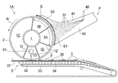
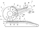
- FIG. 1 is a schematic perspective view showing a first embodiment of the fiber stacking apparatus according to the present invention in a partially transparent manner.
- FIG. 2 is a cross-sectional view schematically showing a method for manufacturing an absorbent body using the fiber stacking apparatus shown in FIG.
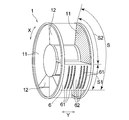
- FIG. 3 is a perspective view showing a fixed drum of the fiber stacking apparatus shown in FIG.
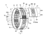
- FIG. 4 is a perspective view showing the rotary drum of the fiber stacking apparatus shown in FIG. 1 with a part of the outer layer portion removed.
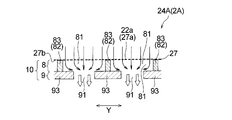
- FIG. 5 is an exploded perspective view of a part of the outer layer portion of the rotating drum shown in FIG.
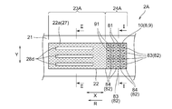
- FIG. 6 is a diagram in which a part of the outer peripheral portion (accumulation concave portion) of the rotating drum shown in FIG. 4 is developed in a planar shape.
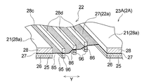
- FIG. 7 is a perspective view schematically showing a cross section taken along line II of FIG.
- FIG. 8 is a cross-sectional view schematically showing a part of a cross section taken along line II of FIG.
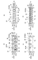
- FIG. 9 is a perspective view schematically showing a section taken along line II-II in FIG.
- FIG. 10 is a cross-sectional view schematically showing a state of suction at each of the accumulation concave portions in the fiber stacking zone (selective suction region, full suction region), and FIG. 10 (a) is an outer layer portion of the rotating drum.
- FIG. 10B shows a state of suction when the adjustment body non-arrangement region of the outer layer portion is positioned in the selective suction region.
- FIG. 10B shows a state of suction when the adjustment body non-arrangement region of the outer layer portion is positioned in the selective suction region.
- FIG. 10 (c) shows the state of suction when the adjusting body non-arrangement region is located in the entire suction region of the fiber stacking zone
- FIG. 10 (d) It is a mode of suction when the adjustment body arrangement region is located in the entire suction region.
- FIG. 11 is a cross-sectional view (corresponding to FIG. 2) schematically showing a method for manufacturing an absorbent body using the second embodiment of the fiber stacking apparatus of the present invention.
- FIG. 12 is a cross-sectional view (corresponding to FIG. 2) schematically showing a method for manufacturing an absorbent body using the third embodiment of the fiber stacking apparatus of the present invention.
- the amount of fiber stacking of the raw materials in the concave portion for accumulation can be partially adjusted, and the basis weight is partially different, that is, the low basis weight portion and the high basis weight portion are high.
- the basis weight is partially different, that is, the low basis weight portion and the high basis weight portion are high.
- the present invention relates to a fiber stacking apparatus capable of stably producing a molded body having a relatively simple structure and partially different raw material stacking amounts.
- a fixed drum and a rotating drum that rotates on the outer periphery of the fixed drum and has a concave portion for accumulation on which the raw material is stacked are provided on the outer peripheral surface, and suction from the fixed drum side while rotating the rotating drum
- a predetermined circumferential direction of the fixed drum is provided.
- the range is a stacking zone in which the raw material can be stacked by suction from the fixed drum side, from when the accumulation concave portion is introduced into the stacking zone by the rotation of the rotating drum until it passes through During this time (suction time), the raw material is piled in the accumulation recess.
- the device configuration is devised so that the high suction portion and the low suction portion are arranged in the rotation direction of the rotating drum on the bottom surface of the concave portion for accumulation, and a pressure loss difference is generated between the two portions from the beginning of the suction time.
- the volume of raw material (basis weight of the absorber) is affected by the pressure loss due to the raw material that is stacked over time in the accumulation recess. It is difficult to control. Accordingly, as another method for controlling the amount of accumulated fibers, a method of providing a difference in the accumulated fiber time instead of providing a suction force difference in the accumulation concave portion is conceivable.
- the part where the amount of accumulated fibers is to be relatively increased (high basis weight planned part) and the part where the amount of accumulated fibers is relatively small (low
- the high basis weight scheduled part is sucked all the time, while the low basis weight scheduled part is sucked from the middle, the high basis weight scheduled part Since the suction time is longer than that of the low basis weight planned portion, it is considered that a significant basis weight difference is formed between the both planned portions.
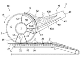
- FIGS. 1 and 2 show a fiber stacking apparatus 1A which is a first embodiment of the fiber stacking apparatus of the present invention
- FIG. 3 shows a fixed drum 1 provided in the fiber stacking apparatus 1A
- 4 shows a rotating drum 2 provided in the fiber stacking apparatus 1A.
- FIGS. 1 and 3 for ease of explanation, the side surface (fixed wall 11 in FIG. 3) on one end side in the axial length direction of the fixed drum 1 is shown in a transparent state.
- the fiber stacking apparatus 1A includes a fixed drum 1 and a rotary drum 2 that rotates on the outer periphery of the fixed drum 1 and has an accumulation recess 22 on the outer peripheral surface 21 in which raw materials are stacked.
- the raw material carried on the air flow generated by suction from the fixed drum 1 side while rotating the drum 2 in the direction of arrow R was formed by a porous plate 27 (porous member) having a plurality of suction holes. It is an apparatus for producing a molded body (absorbent body) by stacking fibers on the bottom surface 22a of the concave portion 22 for accumulation.
- the fiber stacking apparatus 1 ⁇ / b> A further includes a raw material supply mechanism 4 that supplies raw materials to the outer peripheral surface 21 of the rotating drum 2 (an outer peripheral surface 21 on the stacking zone S described later), and a stacking fiber in the accumulation recess 22 of the rotating drum 2. And a discharging mechanism 5 for sequentially releasing the piled material 3 (absorber) of the raw materials.
- the raw material supply mechanism 4 includes a duct 41 having a supply path 40 inside, and a raw material introduction mechanism 45 for introducing the raw material into the duct 41.
- One end side of the duct 41 covers a part of the outer peripheral surface 21 of the rotating drum 2, and a raw material introduction mechanism 45 is disposed on the other end side.
- the raw material introduction mechanism 45 is configured to pulverize a sheet-like wood pulp 46 with a pulverizer 47 to obtain pulp fibers (fiber material), and to feed the pulp fibers into the duct 41.
- a water-absorbing polymer introduction portion 48 for introducing water-absorbing polymer particles is provided in the middle of the duct 41.
- the discharge mechanism 5 is disposed in the fixed drum 1 (space 1D), and generates a blow for transfer that blows air toward the bottom surface 22a (porous plate 27) of the accumulation recess 22 of the rotary drum 2.
- a mechanism 51 and a vacuum conveyor 52 for sucking and conveying the piled article 3 released from the recess 22 are provided.
- the vacuum conveyor 52 is configured in the same manner as a normal vacuum conveyor in this type of fiber stacking apparatus, and although not shown, an endless breathable belt 53 spanned between a driving roll and a driven roll,
- a vacuum box 54 is provided at a position facing the fixed drum 1 with the air-permeable belt 53 interposed therebetween.
- the fiber 3 in the recess 22 is separated from the porous plate 27 by blowing air from the inside of the fixed drum 1 by the blow generating mechanism 51 at the lowest point of the fixed drum 1, and is placed on the vacuum conveyor 52. It is designed to be transcribed.
- the fixed drum 1 has a cylindrical shape, and openings at both ends of the cylinder are hermetically sealed by a fixed wall 11 and a sealing material (not shown) such as felt, respectively.
- the fixed drum 1 does not rotate.
- the inside of the fixed drum 1 is partitioned in the circumferential direction by a partition wall 12, and the spaces 1 ⁇ / b> A, 1 ⁇ / b> B, 1 ⁇ / b> C, and 1 ⁇ / b> D that are partitioned by the partition wall 12 in the fixed drum 1.
- And 1E are formed.
- a pressure reducing mechanism (not shown) for reducing the pressure inside the fixed drum 1 is connected to the fixed drum 1.
- the decompression mechanism includes an exhaust pipe (not shown) connected to the fixed wall 11 and an exhaust fan (not shown) connected to the exhaust pipe.
- an exhaust pipe (not shown) connected to the fixed wall 11
- an exhaust fan (not shown) connected to the exhaust pipe.
- the fixed drum 1 has a predetermined range in the drum circumferential direction X, specifically, the spaces 1A and 1B whose outer peripheral portions are covered with the duct 41 can be stacked with raw materials by suction from the fixed drum 1 side. It is considered to be a thick pile zone S.
- the rotary drum 2 is rotated in a state where the spaces 1A and 1B of the fixed drum 1 are maintained at a negative pressure, the bottom surface 22a (porous) of the recess 22 is passed while the stacking recess 22 passes over the spaces 1A and 1B.
- the negative pressure in each of the spaces 1A and 1B acts on the conductive plate 27), and air is sucked through a number of suction holes formed in the bottom surface 22a.
- the suction through the suction hole the raw material conveyed in the duct 41 is guided to the recess 22 and piled on the bottom surface 22a.
- the space 1C is normally maintained at a negative pressure from the viewpoint of sucking and holding the piled material in the accumulation recess 22 until it is transferred onto the vacuum conveyor 52. It is set to be weaker than 1B.
- the spaces 1D and 1E are usually set to zero pressure (atmospheric pressure) or positive pressure because they are a transfer region of the piled material in the concave portion 22 and a passage region of the concave portion 22 after the transfer.
- the space 1D is partitioned by the partition wall 12 from the space 1E that becomes the post-transfer region from the viewpoint of satisfactorily transferring the piled material in the recess 22.
- a selective suction region S ⁇ b> 1 in which suction from the fixed drum 1 side is partially enabled on the outer peripheral portion of the fixed drum 1 in the stacking zone S, and the suction Are arranged in this order in the rotation direction R of the rotary drum 2.
- the selective suction region S1 corresponds to the space 1A
- the full suction region S2 corresponds to the space 1B.
- the selective suction region S1 of the fixed drum 1 is configured to include a suction control body 6 disposed to face the inner peripheral surface of the rotary drum 2. That is, the outer peripheral portion of the space 1 ⁇ / b> A of the fixed drum 1 that is the selective suction region S ⁇ b> 1 is covered with the suction control body 6.
- the suction control body 6 has a plurality of control body openings 61 that penetrate the suction control body 6 in the thickness direction.
- the plurality of control body openings 61 each have a rectangular shape extending in the drum circumferential direction X of the fixed drum 1, and a plurality (six) are formed at predetermined intervals in the drum width direction Y orthogonal to the drum circumferential direction X. ing.
- the plurality of control body openings 61 have the same shape and the same size in a plan view and are in the same position in the drum circumferential direction X.
- the “plan view” means that the control body opening 61 is outside the normal direction of the outer surface of the suction control body 6 (the outer peripheral surface of the fixed drum 1) (the direction perpendicular to the central axis direction of the fixed drum 1). It means the case seen from the direction.
- the portion other than the control body opening 61 in the suction control body 6 is a non-breathable control body non-suction section 62 that does not allow air to pass therethrough.
- “non-breathable” includes both “non-breathable that does not allow air to pass through” and “non-breathable that allows a very small amount of air to pass but does not substantially allow air to pass through”. It means sex. That is, the selective suction region S1 (the outer peripheral portion of the space 1A of the fixed drum 1) in which the suction control body 6 is arranged can be sucked from the inside of the fixed drum 1 only at the control body opening 61.
- the air flow (vacuum air) generated by the suction passes through the control body opening 61 and does not pass through the control body non-suction part 62.
- a metal such as stainless steel, aluminum, iron, or a resin can be used as a forming material of the suction control body 6 (non-suction part 62).
- a non-breathable member that prevents suction from the inside of the fixed drum 1 such as the suction control body 6 is not arranged in the entire suction region S2 (outer peripheral portion of the space 1B) of the fixed drum 1.
- the air volume (suction air volume) when the air flow generated by the suction flows on the outer peripheral portion of the fixed drum 1 is not substantially suppressed.
- the rotary drum 2 has a cylindrical shape like the fixed drum 1, and has an accumulation recess 22 on the outer peripheral surface 21 in which raw materials are stacked.
- a plurality of recesses 22 are formed at predetermined intervals in the drum circumferential direction X of the rotary drum 2.
- the rotary drum 2 receives power from a motor (not shown) such as a motor, and rotates the outer periphery of the fixed drum 1 in the direction of arrow R with the center line axis of the fixed drum 1 as a rotation axis.
- the rotating drum 2 has a cylindrical outer layer portion 2A including a porous plate 27, and a cylindrical inner layer portion 2B closer to the fixed drum 1 than the outer layer portion 2A.
- the inner layer portion 2 ⁇ / b> B is one member continuous over the entire length in the drum circumferential direction X of the rotary drum 2
- the outer layer portion 2 ⁇ / b> A has a drum circumference. It consists of a plurality of members arranged in a row in the direction X, and one concave portion 22 for accumulation is formed in each member.
- the outer layer portion 2A (a plurality of members constituting the outer layer portion 2A) is detachably fixed to the outer peripheral surface of the inner layer portion 2B by a known fixing mechanism such as a bolt or an adhesive.
- the outer layer portion 2 ⁇ / b> A of the rotary drum 2 includes a suction adjustment plate 25, a space plate 26 that is overlapped and fixed on the outer surface 25 a side of the suction adjustment plate 25, and the outer surface 26 a side of the space plate 26.
- the plates 25 to 28 are fixed to each other by a known fixing mechanism such as a bolt or an adhesive.
- the bottom surface 22 a of the accumulation concave portion 22, which is a fiber surface to be stacked with raw materials, is formed from the porous plate 27.
- the pattern forming plate 28 has an outer surface 28a that forms the outer peripheral surface 21 of the rotating drum 2 and an inner surface 28b that faces the rotating shaft side of the rotating drum 2, and an accumulation recess is provided between the outer surface 28a and the inner surface 28b.
- 22 has a space portion 28c having a shape corresponding to the three-dimensional shape in 22.
- a non-breathable non-suction portion 28d that does not allow air to pass is disposed in the space 28c.
- the non-suction portion 28d has a rectangular shape extending in the drum circumferential direction X of the rotary drum 2 in plan view, and a plurality (three) of non-suction portions 28d are arranged at predetermined intervals in the drum width direction Y of the rotary drum 2.
- the “plan view” refers to an object (such as a concave portion for accumulation) viewed from the outside in the normal direction of the outer peripheral surface 21 of the rotating drum 2 (direction perpendicular to the rotating shaft direction of the rotating drum 2). Means the case.
- the non-suction portion 28 d is fixed to the outer surface 27 a of the porous plate 27 by being connected to the non-suction portion 86 of the space plate 26 by a fixing mechanism such as a bolt via the porous plate 27.
- the non-suction part 86 of the space plate 26 is connected to the non-suction part fixing part 96 of the suction adjustment plate 25 by a fixing mechanism such as a bolt, so that the porous plate 27 is firmly supported.
- a fixing mechanism such as a bolt
- the fixed form of the non-suction part 28d is not limited to this form, and may be a form fixed directly to the outer surface 27a of the porous plate 27 by a known fixing mechanism such as a bolt or an adhesive. good.
- the pattern forming plate 28 is non-breathable so as not to allow air to pass, except for the space portion 28c.
- the “non-breathable” here is as described above.
- a plate, a punched or etched plate, or a superposition of these plates can be used.
- the porous plate 27 transmits an air flow (vacuum air) generated by suction from the stationary drum 1 side to the outside of the rotating drum 2 and holds the raw material carried on the air flow without transmitting it. It is a breathable plate that allows only air to pass through.
- the porous plate 27 is formed with a plurality (a large number) of suction holes (pores) penetrating the plate 27 in the thickness direction with a uniform distribution over the entire plate 27, and the accumulation recess 22 is a fixed drum. While passing through a space maintained at a negative pressure in 1, the suction hole functions as an air flow permeation hole.
- a metal or resin mesh plate, or a metal or resin plate formed with a plurality of (many) pores by etching or punching can be used.
- the outer layer portion 2 ⁇ / b> A of the rotary drum 2 is provided with an adjusting body 10 that adjusts the air flow (the air volume and flow of the air flow) on the inner surface 27 b side of the porous plate 27.
- the adjusting body arrangement area 24A and the adjusting body non-arrangement area 23A in which the adjusting body 10 is not arranged are arranged in the rotation direction R of the rotary drum 2.
- the adjusting body 10 is arranged so as to overlap a part of the inner surface 27 b of the porous plate 27.
- the adjustment body non-arrangement region 23 ⁇ / b> A is located on the front end side in the rotation direction R of each accumulation recess 22, and the adjustment body arrangement region 24 ⁇ / b> A is located on the rear end side. Yes.
- the adjustment body 10 has a multilayer structure in which a plurality of layers are stacked, and is configured by sequentially stacking the first layer 8 and the second layer 9 in the order of proximity to the porous plate 27.
- the adjustment body 10 includes a suction adjustment plate 25 and a space plate 26, and the bottom surface of the recess 22 in the space plate 26 in the plan view of the accumulation recess 22 as shown in FIG. Part of the portion overlapping 22 a is the first layer 8, and the portion of the suction adjustment plate 25 overlapping the first layer 8 is the second layer 9.
- the first layer 8 has a plurality of first openings 81 penetrating the first layer 8 in the thickness direction, and opening defining portions 82 for partitioning the first openings 81.
- the opening defining portion 82 includes a plurality of MD defining members 83 extending in the transport direction R (drum circumferential direction X) of the accumulation recess 22 and a plurality extending in the direction orthogonal to the transport direction (drum width direction Y). And a CD defining member 84 of the book.
- MD defining member “extending in the conveying direction of the stacking concave portion” means that the MD defining member may extend substantially in the transporting direction.
- the definition member is not limited to a straight line parallel to the conveyance direction, and includes a case where the MD definition member is curved along the conveyance direction, and the MD definition member is not parallel to the conveyance direction. Includes a case where the angle formed with the transport direction is along a crossing direction of 45 ° or less.
- “extending in the direction (orthogonal direction) perpendicular to the conveying direction of the stacking recess” means that the CD defining member extends substantially in the orthogonal direction. 22 in a plan view, the CD defining member is not limited to a linear shape parallel to the orthogonal direction, and includes a case where the CD defining member is a curved shape along the orthogonal direction. This includes the case where the angle formed with the orthogonal direction is not parallel to the orthogonal direction but is along a crossing direction of 45 ° or less.
- the opening defining portion 82 includes six MD defining members 83 that are linear in plan view parallel to the drum circumferential direction X of the rotating drum 2. , And 5 linear CD definition members 84 in plan view parallel to the drum width direction Y of the rotary drum 2, and a total of 10 linear definition members 83 and 84 in plan view, It is formed in a lattice shape in plan view.
- the first opening portion 81 is located at a portion of the lattice of the lattice-like opening portion defining portion 82 and has a quadrangular shape in plan view.
- the opening defining part 82 (defining members 83 and 84) has a non-breathable property that does not allow air to pass therethrough.
- the “non-breathable” here is as described above.
- a metal such as stainless steel, aluminum, iron, or a resin can be used.
- a second opening 91 that penetrates the second layer 9 in the thickness direction is formed in a portion of the second layer 9 that overlaps the plurality of first openings 81 in a plan view of the concave portion 22 for accumulation as shown in FIG.
- the first openings 81 are formed so as to correspond to the first openings 81, and the openings 81 and 91 having the corresponding relationship overlap each other in the plan view.
- one second opening 91 of the second layer 9 corresponds to one first opening 81 of the first layer 8.
- the first opening 81 and the second opening 91 correspond one-to-one.
- the second opening 91 is located at a position separated from the CD defining member 84 in each of the plurality of first openings 81, and in the second layer 9.
- a portion overlapping the CD defining member 84 (hereinafter also referred to as a CD defining member corresponding portion) and the vicinity thereof have a non-breathable property that prevents air from passing therethrough.
- the “non-breathable” here is as described above.
- Reference numeral 92 in FIG. 5 indicates the CD defining member corresponding portion of the second layer 9 and its vicinity.
- the CD defining member corresponding portion and its vicinity 92 are formed of a non-breathable material such as a metal such as stainless steel, aluminum or iron, or a resin, and an opening (second portion). It does not have a through-hole penetrating the layer 9 in the thickness direction, and has air permeability.
- “in the vicinity of the CD defining member corresponding portion” means that one CD defining member covers the entire length in the drum width direction Y of one CD defining member 84 in the plan view of the concave portion 22 for accumulation. 84, and has a certain width (length in the drum circumferential direction X) W1 (see FIG. 7).
- the width of the CD defining member corresponding portion (the length in the drum circumferential direction X) is the same as the width W2 of the corresponding CD defining member 84 (see FIG. 7).
- the second layer 9 in the first embodiment has not only the CD defining member 84 but also the MD defining member 83 and a portion overlapping therewith and a non-breathable portion that does not allow air to pass therethrough. That is, in the plan view of the accumulation recess 22 as shown in FIG. 6, the second opening 91 is located away from the MD defining member 83 inside each of the plurality of first openings 81 and the second layer 9.
- the portion that overlaps the MD defining member 83 hereinafter also referred to as the MD defining member corresponding portion
- the “non-breathable” here is as described above.
- the MD defining member corresponding portion and its vicinity 93 are formed of a non-breathable material such as stainless steel, aluminum, iron or the like, or resin, like the other portions of the suction adjusting plate 25, and the opening portion (second portion). It does not have a through-hole penetrating the layer 9 in the thickness direction, and has air permeability.
- “in the vicinity of the MD defining member corresponding portion” means that the one MD defining member covers the entire length in the drum circumferential direction X of one MD defining member 83 in the plan view of the accumulation recess 22. 83, and has a constant width (length in the drum width direction Y) W3 (see FIG. 7). Further, the width of the MD defining member corresponding portion (the length in the drum width direction Y) is the same as the width W4 (see FIG. 7) of the corresponding MD defining member 83.
- the two MD defining members 83 and 83 that are opposed to each other are located at positions apart from each other. Accordingly, the second opening 91 existing inside one first opening 81 in a plan view of the recess 22 has a smaller opening area than the first opening 81.
- the “opening area” of the openings 81 and 91 is the opening at the opening end closest to the porous plate 27 in the opening (the first opening 81 and the second opening 91). It means an area (in the case where the opening and the porous plate are in contact with each other), the area of the contact area.
- the adjustment body 10 since the first opening 81 and the second opening 91 overlap each other in plan view of the accumulation recess 22, the adjustment body 10 (first It can be said that one opening is formed penetrating the layer 8 and the second layer 9) in the thickness direction. As described above, since the second opening 91 existing inside the first opening 81 in the plan view of the recess 22 has a smaller opening area than the first opening 81, both openings In consideration of the magnitude relationship between 81 and 91, the adjustment body 10 in the first embodiment includes a plurality of adjustment body openings (first openings overlapping each other in plan view of the recess 22) that penetrate the adjustment body 10 in the thickness direction.
- the adjustment body opening is an opening end portion relatively far from the porous plate 27 (the opening end of the second opening portion 91). It can be said that the opening area is small compared to the opening end portion (opening end portion of the first opening portion 81) that is relatively close to the opening portion.
- the second opening 91 is formed at the center of each of the plurality of first openings 81 in the plan view of the concave portion 22 for accumulation. Further, in the first embodiment, in the plan view of the recess 22, the first opening 81 and the second opening 91 existing inside thereof are similar in plan view shape to each other. Both the parts 81 and 91 have a quadrangular shape in plan view. That is, regarding the shape of the openings 81 and 91 in plan view, the second opening 91 has a similarity ratio of less than 1 with respect to the corresponding first opening 81.
- the adjusting body disposition region 24 ⁇ / b> A has the adjusting body 10 (first layer 8, second layer 9) on the inner surface 27 b side of the porous plate 27 that forms the bottom surface 22 a of the accumulation recess 22. Therefore, the air flow (vacuum air) that sucks the raw material generated by suction from the fixed drum 1 side flows through the porous plate 27 as compared with the adjustment body non-arrangement region 23A in which this is not arranged. The air volume (suction air volume) is suppressed. That is, as shown in FIG. 8, the air flow (indicated by an arrow in FIG.
- the porous plate 27, the first layer 8, and the second layer 9 are passed through the constituent members of the rotating drum 2 in this order.
- the second opening 91 of the second layer 9, which is located leeward of the air flow and substantially functions as a suction part for the raw material is located at the first leeward of the air flow rather than the second opening 91. Since the opening area is made smaller than the first opening portion 81 of the layer 8, the air permeability of the porous plate 27 is hindered in the adjusting body arrangement region 24 ⁇ / b> A. Is suppressed.
- the amount of the raw material stacked (basis weight of the molded body) is the amount of air flowing through the porous plate 27.
- the adjusting body 10 in a region corresponding to a portion on the inner surface 27b side of the porous plate 27 corresponding to a portion where the basis weight of the raw material to be stacked is smaller than that of the other portion, A compact with a reduced amount can be produced with simple equipment.
- absorbent raw materials such as pulp fibers and water-absorbing polymer particles are used in parts that require high absorption capacity. It is possible to obtain an absorbent body excellent in both absorption performance and discomfort / discomfort by reducing the basis weight as much as possible by using the adjusting body 10 as much as possible, and by making the other parts concentrate. .
- the second opening substantially functions as a raw material suction portion at the bottom surface 22a.
- the difference in the air volume of the air flow becomes significant.
- the amount of accumulated fibers in the portion there is a possibility that unevenness in the accumulated fibers due to such a difference in the amount of accumulated fibers may occur in the arrangement region of the adjustment body 10 where the amount of accumulated fibers should be uniform.
- the first opening 81 having an opening area larger than that of the second opening 91 is provided on the wind flow of the air flow than the second opening 91, thereby
- a space of a predetermined capacity composed of the first opening 81 is formed between the porous plate 27 and the second opening 91, the air flow that has passed through the porous plate 27 flows into the second opening 91. By passing through this space before passing through, it is rectified. As a result, the variation in the air volume of the air flow in the porous plate 27 is reduced, and the occurrence of uneven stacking is effectively prevented.
- each of the widths W2 and W4 is preferably 5 mm or less, and more preferably 2 mm or less.
- the second opening 91 overlaps with the CD defining member 84 in the plan view of the accumulation recess 22, or the CD defining member corresponding portion of the second layer 9 and its vicinity 92 are air-permeable.
- the plurality of first openings 81 are recessed 22 via the second opening 91 overlapping the CD defining member 84 or the air permeable part. Air flow in the transport direction R (drum circumferential direction X) in such a manner that they can communicate with each other.
- the rear side first is caused by suction from the second opening 91 or the air-permeable portion. Suction at the opening 81 is started.
- the rear first opening 81 communicated with the front first opening 81 is the other rear first opening 81 not communicated with the front first opening 81 or the front first opening 81.
- the fibers are accumulated more than the amount that should be originally accumulated, and there is a possibility of causing unevenness in the accumulation.
- This can also be said in the MD direction.
- the second opening 91 overlaps the CD defining member 84 in the plan view of the stacking concave portion 22, the second opening 91 is in the MD direction (drum
- the area ratios exposed (wrapped) with respect to the first openings 81, 81 in the front and rear in the circumferential direction X) are different, the second openings 91 are exposed (wrapped) relatively much. Since a large amount of wind flows through one opening 81, the same problem as described above may occur. Even when the area ratio is the same in design, it may be easily biased to either one depending on the assembly accuracy of the apparatus, and it is difficult to solve the aforementioned problem.
- the second opening 91 is separated from the CD defining member 84 inside each of the plurality of first openings 81 in the plan view of the accumulation recess 22.
- the portion corresponding to the CD defining member of the second layer 9 and its vicinity 92 are non-breathable portions that do not allow air to pass therethrough, and the plurality of first openings 81 are air in the conveying direction R of the recesses 22.
- the flows are not in communication with each other so that they can pass through. Therefore, before the rear first opening 81 passes through the space maintained at the negative pressure of the rotary drum 2, the second opening 91 or the portion corresponding to the CD defining member of the second layer 9 and its vicinity 92 are provided. There is no fear that the suction at the rear first opening 81 starts due to the suction from the side, and uneven fiber accumulation due to the timing of the suction start as described above can be prevented.
- the second opening 91 is located not only from the CD defining member 84 but also from the MD defining member 83 extending in the direction orthogonal thereto, and
- the portion of the second layer 9 that overlaps the opening defining portion 82 and the vicinity thereof (92, 93) are non-breathable portions.
- the plurality of first openings 81 are not in communication with each other so that an air flow can pass in both the transport direction R of the accumulation recess 22 and the direction orthogonal thereto, and the space formed by the first openings 81.
- the second opening 91 is exposed (wrapped) with respect to the front and rear first openings 81. It is possible to completely prevent unevenness in the pile due to the different area ratios. Furthermore, by ensuring the independence of the space (small room) composed of the first openings 81, the suction force is controlled for each space, thereby freely controlling the basis weight of the molded body.
- the adjustment body non-arrangement area 23A is a high basis weight part
- the front side of the rotation direction R in the adjustment body arrangement area 24A is a medium basis weight part
- the rear side of the rotation direction R in the adjustment body arrangement area 24A is a low basis weight. It is possible to form a basis weight gradation such as a part.
- the second opening 91 is formed in the center of each of the plurality of first openings 81 in the plan view of the accumulation recess 22, and further, the recess 22.
- the first opening 81 and the second opening 91 existing in the first opening 81 are similar to each other in plan view. These configurations are effective for stable expression of the rectifying effect by the first opening 81 described above.
- the space plate 26 is disposed in the thickness direction in a portion other than the first layer 8 in the space plate 26.
- the first large opening 85 having a rectangular shape in plan view having a larger opening area than the first opening 81 is formed, and the suction adjustment plate 25 is arranged in the thickness direction.
- a penetrating second large opening 95 having a rectangular shape in plan view is formed corresponding to the first large opening 85.
- the openings 85 and 95 have a congruent relationship in plan view, and the second large opening 95 has a similarity ratio of 1 to the first large opening 85.
- the non-suction portions 28d are arranged corresponding to the non-suction portions 28d, and the non-suction portions 28d and 86 having such a correspondence relationship overlap each other with the porous plate 27 interposed therebetween in the plan view.
- the non-suction parts 86 have the same shape and dimensions as the non-suction part 28d in plan view, and are arranged in the same number (three) as the non-suction parts 28d at a predetermined interval in the drum width direction Y of the rotary drum 2.
- a non-breathable non-suction portion fixing portion 96 for fixing the non-suction portion 86 is arranged in the second large opening 95 of the suction adjustment plate 25 corresponding to the non-suction portion 86 of the space plate 26.
- the non-suction portion fixing portion 96 is continuous over the entire length of the second large opening 95 in the drum circumferential direction X.
- the air permeability inherent to the porous plate 27 is not hindered as in the adjustment body arrangement region 24A.
- the air volume (vacuum air) generated by the suction from the drum 1 side and sucking the raw material is not suppressed when the air flow (vacuum air) flows through the porous plate 27. Therefore, compared to the adjusting body arrangement region 24A, the raw material Is piled up to a high basis weight.
- the concave portion 22 for accumulation in the first embodiment includes an adjustment body non-arrangement region (high basis weight product fiber region) 23 that causes the raw material to be deposited at a relatively high basis weight, and An adjustment body arrangement region (low basis weight stacking region) 24 for stacking raw materials at a relatively low basis weight is provided in the conveying direction R (longitudinal direction) of the recess 22.
- the inner layer portion 2B of the rotary drum 2 has an inner layer portion 2B arranged on the adjustment body arrangement region side 24B (a region overlapping the adjustment body arrangement region 24A in plan view of the accumulation recess 22).
- a non-breathable partition member 71 is disposed that is divided into a non-arrangement region side 23B (a region that overlaps with the adjustment member non-arrangement region 23A in the plan view), and in the adjustment body arrangement region side 24B of the inner layer portion 2B.
- the control body opening 61 of the selective suction region S1 of the fixed drum 1 is closed at a position not corresponding to the adjustment body opening (opening constituted by the first opening 81 and the second opening 91).
- a non-breathable opening closing member 73 is provided.
- the “non-breathable” here is as described above.
- a portion corresponding to a part (adjustment body arrangement area 24A) of the plurality (two) of the recess 2 corresponds to the fixed drum 1
- a non-breathable opening closing member 73 is disposed that overlaps and closes the control body opening 61 of the area S1 when positioned on the selective suction area S1.
- the accumulation concave portion 2 is divided into two regions, that is, an adjustment member non-arrangement region 23 ⁇ / b> A and an adjustment member arrangement region 24 ⁇ / b> A in the rotation direction R of the rotary drum 2 by a non-breathable division member 71.
- the opening closing member 73 corresponds to the adjustment body opening (the opening formed by the first opening 81 and the second opening 91) on the adjustment body arrangement region side 24B of the inner layer 2B of the rotary drum 2. It is not located.
- the inner layer portion 2B will be further described.
- a space portion 70 in which the forming material of the inner layer portion 2B does not exist It is formed continuously over the entire length in the drum circumferential direction X, and a partition member 71 and an opening closing member 73 are disposed in the space 70.
- the length of the space portion 70 in the drum width direction Y is the same as the length (maximum length) of the accumulation recess 22 of the outer layer portion 2A in the drum width direction Y. Entirely overlaps the space portion 70.
- the inner layer portion 2 ⁇ / b> B has non-breathability that does not allow air to pass except for the space portion 70.
- the “non-breathable” here is as described above.
- Examples of the material for forming the inner layer portion 2B include metals such as stainless steel, aluminum, and iron, or non-breathable materials such as resins.
- the division member 71 is disposed at or near the boundary between the adjustment body non-arrangement region side 23B and the adjustment body arrangement region side 24B of the inner layer portion 2B (space portion 70) and extends in the drum width direction Y in plan view. It has a shape.
- the sorting member 71 is continuous over the entire length of the space 70 in the drum width direction Y.
- a plurality of rectangular auxiliary partition members 72 extending in the drum width direction Y are arranged in the space portion 70.
- the auxiliary sorting member 72 has the same shape and dimensions as the sorting member 71 in plan view.
- the plurality of partition members 71 and 72 are arranged at equal intervals in the drum circumferential direction X of the space 70.
- the space portion 70 is partitioned into a plurality of regions by a plurality of partition members 71 and 72 extending in the drum width direction Y and a plurality of opening closing members 73 extending in the drum circumferential direction X, and has a lattice shape in plan view. There is no.
- the opening closing member 73 is disposed in each portion (concave portion corresponding portion) corresponding to any one stacking concave portion 22 (adjustment body arrangement region 24A) in the inner layer portion 2B.
- the same number of opening closing members 73 as the (six) control body openings 61 are arranged at the same position as the control body openings 61 in the drum width direction Y. That is, a plurality (six) of the opening closing members 73 in any one of the concave portion corresponding parts of the inner layer part 2B and a plurality (six) of the control drum openings 61 of the fixed drum 1 correspond one-to-one. ing.
- the opening closing member 73 has a rectangular shape extending in the drum circumferential direction X in plan view, and is disposed between the partition member 71 and the auxiliary partition member 72.
- the length (width) of the opening closing member 73 in the drum width direction Y is the same as or equal to the length (width) of the control body opening 61 in the drum width direction Y from the viewpoint of reliably closing the control body opening 61. Has been made bigger than.
- FIG. 10 when any one collecting concave portion 22 formed in the outer layer portion 2 ⁇ / b> A of the rotary drum 2 is introduced into the stacking zone S (selective suction region S ⁇ b> 1, full suction region S ⁇ b> 2).
- FIG. 10A shows the state of suction when the adjusting body non-arrangement region 23A of the outer layer portion 2A is located in the selective suction region S1 of the inner layer portion 2B
- FIG. 10B shows the adjustment of the outer layer portion 2A.
- FIG. 10C shows a state of suction when the body placement region 24A is located in the selective suction region S1, and FIG.
- FIG. 10C shows that the adjustment body non-placement region 23A is located in the entire suction region S2 of the inner layer portion 2B.
- FIG. 10 (d) shows the state of suction when the adjusting body arrangement region 24A is located in the entire suction region S2.
- the selective suction area S 1 and the entire suction area S 2 are arranged in this order with respect to the rotation direction R of the rotary drum 2.
- any one recess 22 formed in the outer layer portion 2A of the first passage first passes through the selective suction region S1 (see FIG. 10 (a) and FIG. 10 (b)). Then, it passes through the entire suction region S2 (see FIGS. 10C and 10D).
- the porous plate 27 that forms the bottom surface 22a of the accumulation recess 22 is formed in the adjustment body non-arrangement region 23A as shown in FIG. Is generated from the outside of the rotary drum 2 through the porous plate 27 toward the inside of the fixed drum 1 (indicated by arrows in FIG. 10).
- the raw material 30 transported by loading is stacked on the bottom surface 22a.
- the opening closing member 73 of the inner layer portion 2B of the rotary drum 2 overlaps the control body opening 61 and closes it, so that the suction is hindered.
- the air flow is not generated, and the raw material is not stacked on the bottom surface 22 a of the recess 22.
- the suction control body 6 that was present in the selective suction region S1 does not exist, so that the suction is not substantially hindered.
- the air flow is generated, and the raw material 30 is piled on the bottom surface 22a of the recess 22.
- the adjustment body arrangement area 24A has the suction of the adjustment body non-arrangement area 23A from the introduction to the entire suction area S2. Since a suction force similar to the suction force at the beginning of time acts, the raw materials are concentrated to fill the pressure loss difference with the adjustment member non-arrangement region 23A. It becomes difficult to form a significant basis weight difference of the raw material between the arrangement region 23A and the adjustment body arrangement region 24A (that is, uneven distribution of the raw material at a high magnification).
- the adjustment body arrangement area 24A since the adjustment body 10 that lowers the suction force is arranged in the adjustment body arrangement area 24A, the adjustment body arrangement area 24A has an increased pressure loss at the initial stage of suction.
- the position of the body placement region 24A is switched from the selective suction region S1 to the full suction region S2, the raw material is not concentrated in the adjustment body placement region 24A. As a result, the high magnification of the raw material is not increased. Uneven distribution is possible.
- the adjustment body In order to express the difference in the suction force (suction air volume) between the adjustment body non-arrangement area 23A and the adjustment body arrangement area 24A in the outer layer portion 2A of the rotary drum 2, the adjustment body only to the adjustment body arrangement area 24A is used. In addition to the use of 10, it is also necessary to use the dividing member 71. That is, as shown in FIG. 4, the adjustment is made by providing the non-breathable partition member 71 at or near the boundary between the adjustment body arrangement area side 24B and the adjustment body non-position area 23B in the inner layer portion 2B.
- the body arrangement area side 24B and the adjustment body non-arrangement area side 23B are not in communication with each other so that an air flow can pass in the conveyance direction of the accumulation recess 22 (the rotation direction R of the rotary drum 2). Accordingly, it is possible to prevent the inconvenience that the adjustment body arrangement area 24A starts to be sucked before the adjustment body arrangement area 24A is introduced into the selective suction area S1 or the entire suction area S2. Further, in the first embodiment, since the auxiliary division member 72 is further arranged in the inner layer portion 2B (space portion 70) in addition to the division member 71, a certain division member 71 or a certain auxiliary division member 72 is a rotating drum.
- the area in the MD direction in which suction is started when entering the fiber stacking zone S beyond the partition wall 12 of the fixed drum 1 with the rotation of 2 becomes narrower, and the adjustment body non-arrangement area 23A and the adjustment body arrangement area 24A.
- the shift of the suction start position of each part can be suppressed. Thereby, problems such as the above-mentioned unevenness in piled fiber can be more effectively prevented, and the suction force and the suction time can be more reliably controlled.
- the first opening portion 81 existing in the region partitioned by the two partition members 71 and 72 adjacent in the MD direction.
- the suction start position may be shifted between the second opening 91 located on the front side relative to the rotation direction and the second opening 91 located on the rear side.
- the auxiliary division member 72 is located at a position corresponding to all of the plurality of CD defining members 84 which are one of the members that substantially define the second opening 91, in other words.
- the plurality of auxiliary division members 72 correspond to the plurality of CD defining members 84 on a one-to-one basis.
- a portion (a high basis weight scheduled portion) where the amount of fiber piles is to be relatively increased is desired to be relatively reduced.
- the suction time (stacking time) of both planned parts is made different, and the low basis weight scheduled part Is the adjustment body arrangement region 24 in which the adjustment body 10 that reduces the suction force is disposed, and the high basis weight planned portion is the adjustment body non-arrangement region 23 in which the adjustment body 10 is not disposed, and suction in the recess 22
- the force it is possible to arbitrarily distribute the raw material in the concave portion 22, and as a result, it is possible to stably produce a molded body in which the amount of the raw material is partially different.
- FIGS. a method for continuously manufacturing an absorbent body (stacked fiber 3) using the fiber stacking apparatus 1A described above, that is, an embodiment of a method for manufacturing the absorbent body of the present invention, is mainly shown in FIGS.
- the manufacturing method of this embodiment includes a fiber stacking step in which raw materials supplied in an air stream are sucked into the stacking recesses 22 of the fiber stacking apparatus 1A for stacking.
- the raw material of the absorbent body various materials used for absorbent bodies of absorbent articles such as sanitary napkins, panty liners, and disposable diapers can be used without particular limitation.
- fiber materials and water-absorbing polymer particles Commonly used as the raw material of the absorbent body are fiber materials and water-absorbing polymer particles.
- the fiber material include pulp fibers such as defibrated pulp, short fibers of cellulosic fibers such as rayon fibers and cotton fibers, short fibers of synthetic fibers such as polyethylene, and the like. Two or more kinds can be used in combination.
- pulp fibers (not shown) and water-absorbing polymer particles 31 are used as raw materials for the absorbent body (stacked product 3).
- the pressure reducing mechanism connected to the fixed drum 1 is operated to make the spaces 1A to 1C in the fixed drum 1 have a negative pressure.
- an air flow (vacuum air) is generated in the supply path 40 in the duct 41 to convey the raw material to the outer peripheral surface 21 of the rotating drum 2.
- the rotary drum 2 is rotated in the direction of arrow R in the figure, and the vacuum conveyor 52 is operated.
- the raw material introduction mechanism 45 is operated to supply pulp fibers (not shown) and water-absorbing polymer particles 31 as raw materials to the supply path 40 in the duct 41, the raw material flows through the supply path 40. And is supplied toward the outer peripheral surface 21 of the rotary drum 2 located in the stacking zone S.
- the portion corresponding to the adjustment body non-arrangement region 23A in the accumulation recess 22 is a high suction portion having a relatively large suction air volume
- the adjustment body arrangement in the recess 22 A portion corresponding to the region 24A is a low suction portion with a relatively small suction air volume.
- the high suction portion starts suction simultaneously with the introduction of the high suction portion into the selective suction region S1 as the rotary drum 2 rotates. Suction is performed throughout the time until it passes through the entire suction area S2 (that is, the fiber stacking zone S).
- the raw material is provided at the boundary between the adjustment body non-arrangement area 23A and the adjustment body arrangement area 24A.
- a level difference 35 (see FIG. 2) resulting from the difference in the amount of accumulated fibers is formed, and the surface of the adjustment body arrangement region 24A is located at a relatively low position with respect to the surface of the adjustment body non-arrangement region 23A.
- the final pile height of the raw material (the thickness of the pile 3) is the thickness of the non-suction portion 28d (the bottom surface of the recess 22). If the height does not exceed (the height from 22a), the raw material is not stacked on the outer surface of the non-suction part 28d, and only when the stacking height exceeds the thickness of the non-suction part 28d, the non-suction part 28d. Raw material is piled up on the outer surface of the material. Therefore, in the fiber pile 3, the part 36 (refer FIG.
- the water-absorbing polymer particles 31 are uniformly dispersed throughout the stacked product 3.
- the fixed drum 1 is configured such that the negative pressure (suction force) of each space partitioned by the partition wall 12 can be independently adjusted. Therefore, the portion (space) having the selective suction region S1 can be adjusted. 1A) and the portion having the entire suction area S2 (space 1B) can be adjusted independently of each other. For example, the suction force (suction air volume) of the selective suction area S1 (space 1A) can be adjusted. By making it larger than that of the entire suction area S2 (space 1B), it is possible to more reliably form a significant basis weight difference between the high basis weight part and the low basis weight part in the piled article 3. It becomes.
- the rotating drum 2 is further rotated.
- the fiber 3 in the recess 22 is conveyed while receiving suction from the fixed drum 1 side, and is introduced onto the vacuum conveyor 52 onto the core wrap sheet 37 made of tissue paper or liquid-permeable nonwoven fabric. Transcribed. And as shown in FIG. 1, the both sides along the conveyance direction of the core wrap sheet 37 are turned back, and the upper and lower surfaces of the piled article 3 are covered with the core wrap sheet 37. Thereafter, the piled article 3 covered with the core wrap sheet 37 is cut into a predetermined size together with the core wrap sheet 37 by a cutting device (not shown).
- the thus obtained pile 3 has a relatively high basis weight high basis weight portion made of raw materials piled on the adjustment body non-arrangement area 23 of the recess 22 and an adjustment body arrangement area (low basis weight accumulation fiber area). And a low basis weight portion having a relatively low basis weight composed of raw materials stacked in 24, and is an absorbent body in which the raw fiber weight (basis weight) of the raw materials is partially different, disposable diapers, sanitary napkins, It is a high quality material suitable as an absorbent body for absorbent articles such as incontinence pads.
- an absorbent body used for disposable diapers it is incorporated into an absorbent article so that the high basis weight portion of the piled article 3 is on the ventral side (front side) and the low basis weight portion is on the back side (rear side). It is preferable to be used in view of maximizing the performance of the piled article 3.
- forming a high basis weight part and a low basis weight part having different basis weights (amount of raw material accumulated) in the absorbent body has advantages such as obtaining an absorbent body that is flexible and improved in wearing feeling. .
- an absorbent body in which a low basis weight part is formed before and after or around a high basis weight part is flexible and excellent in wearing feeling.
- the presence of the non-suction portion 28d in the recess 22 forms a slit (a portion 36 corresponding to the non-suction portion 28d; see FIG. 1) in the absorber to be molded.
- a slit a portion 36 corresponding to the non-suction portion 28d; see FIG. 1
- FIG. 11 shows a second embodiment of the fiber stacking device of the present invention (fiber stacking device 1B).
- the supply path 40 in the duct 41 is divided into a plurality (two) of supply areas in the rotation direction R of the rotary drum 2 by a non-breathable plate 49.
- the plurality of supply areas include a first supply area 40A that supplies the raw material to the front end side in the rotation direction R of the selective suction area S1, and other portions and the entire surface other than the front end side in the rotation direction R of the selective suction area S1.
- a second supply region 40B for supplying raw materials to the general suction region S2.
- the water-absorbing polymer introduction part 48 for introducing the water-absorbing polymer particles 31 is not provided in the first supply region 40A, but is provided only in the second supply region 40B. Further, in the portion having the selective suction region S1 in the fixed drum 1, the same number (two) of spaces 1A1 and 1A2 as the plurality of supply regions 40A and 40B are formed.
- the space 1A1 is a portion having a front end side in the rotation direction R of the selective suction region S1 in the fixed drum 1, and the space 1A2 is a portion other than the front end side of the selective suction region in the fixed drum 1. It is a part that has. Further, the fixed drum 1 can adjust the suction force (suction air volume) independently in the space 1A1 and the space 1A2.
- the first supply region 40A can be used as a supply path for the raw material mainly composed of the fiber material. That is, for example, as shown in FIG. 11, only the fiber material such as pulp fiber (not shown) is supplied from the first supply region 40A, and the water-absorbing polymer particles 31 are not supplied. It supplies from the 2nd supply area
- the accumulation recess 22 of the region 23A is formed on the bottom surface 22a. Normally, clogging of a porous plate is likely to occur in a high suction part with a strong suction force. It becomes difficult to perform stably. Therefore, it is desirable to form a fiber material layer in the high suction portion.
- the fiber material layer is formed only in the high suction portion (adjustment body non-arrangement region 23A) being sucked, and is not formed in the low suction portion (adjustment body arrangement region 24A) not sucked. Or, the amount is small with respect to the high suction part.
- the accumulation recess 22 is introduced to the entire suction area S2 located in the second supply area 40B with the suction holes (pores) of the porous plate located in the low suction section exposed.
- the adjustment body that is, “i) the second opening portion 91 of the second layer 9 that substantially functions as a raw material suction portion is provided in the low suction portion of the accumulation recess 22 here.
- the opening area is smaller than that of the first opening 81 of the first layer 8 positioned on the windward side of the air flow than 91, and ii) between the porous plate 27 and the second opening 91.
- it since it has a structure in which a space having a predetermined capacity formed by the first opening 81 is formed, it is possible to prevent clogging even if the fiber material layer is not sufficiently formed.
- the suction force of the region 23A may decrease due to the effect of pressure loss due to the fiber material layer, which may hinder subsequent fiber stacking. It is desirable to adjust the suction force of the space 1A1 to be lower than that of the spaces (space 1A2 and space 1B) located on the rear side in the rotation direction R with respect to the space 1A1.
- FIG. 12 shows a third embodiment (stacking device 1C) of the stacking device of the present invention.
- the second supply region 40B in the duct 41 is placed on another portion (outer peripheral portion of the space 1A2) other than the front end side in the rotation direction R of the selective suction region S1 by the non-breathable plate 49.
- 11 is different from the fiber stacking apparatus 1B shown in FIG. 11 in that it is divided into a front region 40B1 for supplying raw materials and a rear region 40B2 for supplying raw materials to the entire suction region S2. Further, in the front region 40B1 and the rear region 40B2, a water absorbent polymer introduction part 48 for introducing the water absorbent polymer particles 31 is provided independently.
- the control level of pulp fiber (fiber material) and water-absorbing polymer particles are equivalent.
- an absorbent body such as a diaper
- the level of pulp fiber accumulation is limited to a certain level, and the water-absorbing polymer. It is necessary to increase the level of particle accumulation control.
- the manufacturing apparatus 1C of the third embodiment since the two water-absorbing polymer particle supply regions 40B1 and 40B2 that are independent of each other are provided, the amount of water-absorbing polymer particles supplied in the region 40B1 and the region 40B2 In the piled fiber (absorber), apart from fiber materials such as pulp fibers, the water-absorbing polymer particles are unevenly distributed at a high magnification (at the front side and the rear side in the rotation direction R). Uneven distribution) is possible. That is, it is possible to obtain an absorber that satisfies the above requirements.
- the present invention is not limited to the above embodiment and can be modified as appropriate.
- the 1st layer 8 and the 2nd layer 9 which comprise the adjustment body 10 were each a different body (refer FIG. 5), both layers 8 and 9 were integrally formed (the adjustment body 10 is 1). It may be formed from a plate of layers).
- the adjustment body 10 was the 2 layer structure formed by laminating
- the accumulation recess 22 is intermittently formed in the drum circumferential direction X of the rotary drum 2, but may be continuously formed over the entire length in the circumferential direction 2. All the parts of only one embodiment described above can be used as appropriate.
- the absorbent body produced in the present invention is preferably used as an absorbent body for absorbent articles.
- the absorbent article is mainly used to absorb and retain body fluids excreted from the body such as urine and menstrual blood.
- Absorbent articles include, for example, disposable diapers, sanitary napkins, incontinence pads, panty liners, etc., but are not limited to these, and widely include articles used to absorb liquid discharged from the human body. To do.
- the absorbent article typically includes a top sheet, a back sheet, and a liquid-retaining absorbent disposed between the sheets.
- the upper and lower surfaces of the absorber may be covered with one or a plurality of core wrap sheets.
- the back sheet may or may not have water vapor permeability.
- the absorbent article may further include various members according to specific uses of the absorbent article. Such members are known to those skilled in the art. For example, when the absorbent article is applied to a disposable diaper or a sanitary napkin, a pair or two or more pairs of three-dimensional guards can be arranged on the outer side of both sides of the absorbent body.
- the following additional notes a method for manufacturing a fiber stacking apparatus and an absorbent body are disclosed.
- a fixed drum and a rotating drum that rotates on the outer periphery of the fixed drum and has a concave portion on the outer peripheral surface on which the raw material is piled are provided on the outer peripheral surface.
- the raw material conveyed in the air flow is piled on the bottom surface of the concave portion for accumulation formed by a porous member having a plurality of suction holes, and a molded body in which the amount of the raw material is partially different is manufactured.
- a fiber stacking device The rotating drum has an outer layer portion including the porous member and an inner layer portion closer to the fixed drum than the outer layer portion, and the air is disposed on the inner surface side of the porous member on the outer layer portion of the rotating drum.
- An adjusting body arrangement area in which an adjusting body for adjusting the air volume and flow of the flow is arranged, and an adjusting body non-arrangement area in which the adjusting body is not arranged are arranged in the rotation direction of the rotating drum,
- the adjustment body has a plurality of adjustment body openings that penetrate the adjustment body in the thickness direction, and the adjustment body opening is relatively close to an opening end portion that is relatively far from the porous member.
- the opening area is made smaller than the opening end of the In the fixed drum, a predetermined range in the circumferential direction is a stacking zone in which raw material can be stacked by suction from the fixed drum side, and the fixed drum in the stacking zone has an outer peripheral portion of the fixed drum.
- a selective suction region in which suction is partially enabled and a full suction region in which suction is enabled are arranged in this order in the rotational direction;
- the selective suction region includes a suction control body disposed opposite to the inner peripheral surface of the rotary drum, and the suction control body has a control body opening that penetrates the suction control body in the thickness direction.
- the inner layer portion of the rotating drum is provided with a non-breathable dividing member that divides the inner layer portion into the adjustment body arrangement region side and the adjustment body non-arrangement region side, and the adjustment body of the inner layer portion In a position not corresponding to the adjustment body opening on the arrangement area side, when the adjustment body arrangement area is located on the selective suction area, it overlaps with the control body opening and closes it.
- a fiber stacking device in which a breathable opening closing member is arranged.
- ⁇ 2> The stacking device according to ⁇ 1>, wherein a plurality of the concave portions for accumulation are formed at predetermined intervals in a circumferential direction of the rotating drum.
- ⁇ 3> The fiber stacking apparatus according to ⁇ 1> or ⁇ 2>, wherein the adjustment body has a multilayer structure in which a plurality of layers are stacked.
- the fixed drum is configured such that the suction force can be independently adjusted between the portion having the selective suction region and the portion having the full suction region.
- a duct having a supply path for supplying a raw material to the outer peripheral surface of the rotating drum on the stacking zone, the supply path being divided into a plurality of supply areas in the rotation direction;
- the plurality of supply areas include a first supply area that supplies raw materials to the front end side in the rotational direction of the selective suction area, a portion other than the front end side in the rotational direction of the selective suction area, and the full suction.
- the second supply region is divided into a front region for supplying the raw material to the other part of the selective suction region and a rear region for supplying the raw material to the full suction region.
- the suction force can be independently adjusted between a portion having the front end side in the rotational direction of the selective suction region and a portion having the other portion of the selective suction region.
- the fiber material and water-absorbing polymer particles are used as raw materials
- the first supply region is used as a supply path for raw materials mainly composed of the fiber material according to any one of ⁇ 5> to ⁇ 7>.
- Stacking device is used as a supply path for raw materials mainly composed of the fiber material according to any one of ⁇ 5> to ⁇ 7>.
- ⁇ 9> ⁇ 1> to ⁇ 1> further comprising: a raw material supply mechanism that supplies the raw material to the outer peripheral surface of the rotating drum; and a discharge mechanism that sequentially releases the piled material of the raw material stacked in the accumulation recess.
- the fiber stacking apparatus according to any one of 8>.
- the raw material supply mechanism includes a duct having a supply path inside, and a raw material introduction mechanism for introducing the raw material into the duct, and the duct has one end side covering a part of the outer peripheral surface of the rotating drum,
- the fiber stacking device according to ⁇ 9>, wherein the raw material introduction mechanism is arranged on the other end side.
- the space (space 1A, 1B) covered with the duct and the space (space 1C) located adjacent to the space and on the rear side in the rotation direction of the rotary drum with respect to the space are maintained at negative pressure
- ⁇ 13> There are two spaces in the fixed drum, the outer periphery of which is covered with the duct, along the rotation direction of the rotary drum, and the selective suction region is the rotation of the two spaces.
- ⁇ 14> The stacked fibers according to any one of ⁇ 1> to ⁇ 13>, wherein a portion other than the control body opening in the suction control body is a non-breathable control body non-suction portion that does not allow air to pass therethrough.
- apparatus. ⁇ 15> The fiber stacking device according to any one of ⁇ 1> to ⁇ 14>, wherein a non-breathable member that prevents suction from the inside of the fixed drum is not disposed in the entire suction region.
- the outer layer portion of the rotary drum includes a suction adjustment plate, a space plate fixed to be overlapped on the outer surface side of the suction adjustment plate, the porous plate fixed to be overlapped on the outer surface side of the space plate, and the porous plate. Any one of the items ⁇ 1> to ⁇ 15>, wherein the suction adjustment plate is fixed to the outer peripheral surface of the inner layer portion of the rotary drum.
- the fiber stacking apparatus according to claim 1.
- the pattern forming plate has an outer surface that forms an outer peripheral surface of the rotating drum, and an inner surface that faces the rotating shaft side of the rotating drum. Between the outer surface and the inner surface, The fiber stacking device according to ⁇ 16>, including a space portion having a shape corresponding to a three-dimensional shape, and a non-breathable non-suction portion that does not allow air to pass through the space portion.
- the non-suction portion has a rectangular shape extending in a circumferential direction of the rotating drum in plan view, and a plurality (three) of the non-suction portions are arranged at predetermined intervals in the width direction of the rotating drum. Stacking device.
- the space plate has a plan view that has a larger opening area than the first opening that penetrates the space plate in the thickness direction and is formed in the space plate and constitutes the adjustment body opening.
- a rectangular first large opening is formed, and the suction adjustment plate is provided with a second large opening having a rectangular shape in plan view that penetrates the suction adjustment plate in the thickness direction.
- the first large opening and the second large opening are in a congruent relationship with each other in shape in plan view,
- a portion of the first large opening of the space plate that overlaps the non-suction portion of the pattern forming plate in a plan view of the concave portion for accumulation is a non-breathable non-suction portion of the space plate.
- the fiber stacking apparatus according to ⁇ 17> or ⁇ 18>.
- the rotating drum rotates around the outer periphery of the fixed drum, and by the rotation, first, when the concave portion for accumulation is introduced into the selective suction region, (A) In the adjustment drum non-arrangement region of the rotating drum, the porous member is formed from the outside of the rotating drum by suction from the suction hole of the porous member (porous plate) that forms the bottom surface of the accumulation recess.
- the fiber stacking apparatus according to any one of ⁇ 1> to ⁇ 19>.
- ⁇ 21> The fiber stacking apparatus according to any one of ⁇ 1> to ⁇ 20>, wherein an absorbent body used for absorbent articles such as disposable diapers and sanitary napkins is manufactured as the molded body.
- ⁇ 22> A method for producing an absorbent body using the fiber stacking apparatus according to any one of the above ⁇ 1> to ⁇ 21>, wherein the amount of the raw material is partially different,
- the manufacturing method of the absorber which comprises the fiber-splitting process which attracts
- the portion corresponding to the adjustment body non-arrangement region in the accumulation recess is a high suction portion having a relatively large suction air volume
- the portion corresponding to the adjustment body arrangement region in the accumulation recess is It becomes a low suction part with relatively small suction air volume
- suction is started at the same time as the high suction portion is introduced into the selective suction region as the rotary drum rotates, until the high suction portion passes through the entire suction region.
- the fiber material and the water-absorbing polymer particles are used as the raw material, and the raw material is supplied to the stacking zone in the stacking step so that the water-absorbing polymer particles are unevenly distributed in the circumferential direction of the fixed drum.
- the manufacturing method of the absorber as described in any one of- ⁇ 24>.
Landscapes
- Health & Medical Sciences (AREA)
- Engineering & Computer Science (AREA)
- Vascular Medicine (AREA)
- Epidemiology (AREA)
- Biomedical Technology (AREA)
- Heart & Thoracic Surgery (AREA)
- Manufacturing & Machinery (AREA)
- Life Sciences & Earth Sciences (AREA)
- Animal Behavior & Ethology (AREA)
- General Health & Medical Sciences (AREA)
- Public Health (AREA)
- Veterinary Medicine (AREA)
- Absorbent Articles And Supports Therefor (AREA)
- Nonwoven Fabrics (AREA)
- Warping, Beaming, Or Leasing (AREA)
Priority Applications (1)
| Application Number | Priority Date | Filing Date | Title |
|---|---|---|---|
| CN201480051573.5A CN105556016B (zh) | 2013-09-20 | 2014-09-05 | 积纤装置 |
Applications Claiming Priority (2)
| Application Number | Priority Date | Filing Date | Title |
|---|---|---|---|
| JP2013194866A JP5810141B2 (ja) | 2013-09-20 | 2013-09-20 | 積繊装置 |
| JP2013-194866 | 2013-09-20 |
Publications (1)
| Publication Number | Publication Date |
|---|---|
| WO2015041077A1 true WO2015041077A1 (ja) | 2015-03-26 |
Family
ID=52688728
Family Applications (1)
| Application Number | Title | Priority Date | Filing Date |
|---|---|---|---|
| PCT/JP2014/073537 Ceased WO2015041077A1 (ja) | 2013-09-20 | 2014-09-05 | 積繊装置 |
Country Status (3)
| Country | Link |
|---|---|
| JP (1) | JP5810141B2 (enExample) |
| CN (1) | CN105556016B (enExample) |
| WO (1) | WO2015041077A1 (enExample) |
Families Citing this family (12)
| Publication number | Priority date | Publication date | Assignee | Title |
|---|---|---|---|---|
| JP6170308B2 (ja) * | 2013-02-13 | 2017-07-26 | 花王株式会社 | 吸収体の製造装置 |
| US20180147749A1 (en) * | 2015-05-04 | 2018-05-31 | Gdm S.P.A. | Forming Pocket And Method For Making A Forming Pocket |
| JP6764643B2 (ja) * | 2015-11-24 | 2020-10-07 | 花王株式会社 | 吸収体の製造方法及び吸収体の製造装置 |
| JP6728945B2 (ja) * | 2016-04-28 | 2020-07-22 | 王子ホールディングス株式会社 | 吸収体製造装置および製造方法 |
| JP7261213B2 (ja) * | 2020-11-30 | 2023-04-19 | 花王株式会社 | 吸収体の製造方法及び積繊装置 |
| JP7349422B2 (ja) * | 2020-12-07 | 2023-09-22 | 花王株式会社 | 吸収体の製造方法 |
| JP7366100B2 (ja) * | 2020-12-17 | 2023-10-20 | 花王株式会社 | 積繊装置及び吸収体の製造方法 |
| CN116600755B (zh) * | 2020-12-17 | 2025-09-23 | 花王株式会社 | 积纤装置和吸收体的制造方法以及制造装置 |
| JP2022105905A (ja) * | 2021-01-05 | 2022-07-15 | 花王株式会社 | 吸収体の製造方法及び製造装置 |
| JP7735704B2 (ja) * | 2021-07-28 | 2025-09-09 | セイコーエプソン株式会社 | 解繊装置、繊維体製造装置 |
| CN114404148B (zh) * | 2022-01-26 | 2023-03-28 | 瑞光(上海)电气设备有限公司 | 一种吸收体制造装置 |
| JP7782114B2 (ja) * | 2022-05-31 | 2025-12-09 | 大王製紙株式会社 | 吸収性物品用の吸収体の製造方法 |
Citations (4)
| Publication number | Priority date | Publication date | Assignee | Title |
|---|---|---|---|---|
| JPH02107250A (ja) * | 1988-10-17 | 1990-04-19 | Takao Sakata | 液吸収体並びにその製造方法及び装置 |
| JPH06142B2 (ja) * | 1984-02-01 | 1994-01-05 | ザ、プロクタ−、エンド、ギヤンブル、カンパニ− | 空気集積製品を製造する装置 |
| JP2000178866A (ja) * | 1998-12-17 | 2000-06-27 | Kao Corp | 成形体の製造方法及び製造装置 |
| JP2005288960A (ja) * | 2004-04-02 | 2005-10-20 | Kao Corp | 積層体の積繊装置及び積繊方法 |
Family Cites Families (4)
| Publication number | Priority date | Publication date | Assignee | Title |
|---|---|---|---|---|
| ATE82597T1 (de) * | 1985-12-10 | 1992-12-15 | Kimberly Clark Co | Vorrichtung und verfahren fuer die erzeugung eines faservlieses. |
| JP4522349B2 (ja) * | 2005-09-29 | 2010-08-11 | 大王製紙株式会社 | 吸収体の製造装置 |
| US7549853B2 (en) * | 2006-11-15 | 2009-06-23 | The Procter & Gamble Company | Apparatus for making air-laid structures |
| EP2329803B1 (en) * | 2009-12-02 | 2019-06-19 | The Procter & Gamble Company | Apparatus and method for transferring particulate material |
-
2013
- 2013-09-20 JP JP2013194866A patent/JP5810141B2/ja active Active
-
2014
- 2014-09-05 CN CN201480051573.5A patent/CN105556016B/zh active Active
- 2014-09-05 WO PCT/JP2014/073537 patent/WO2015041077A1/ja not_active Ceased
Patent Citations (4)
| Publication number | Priority date | Publication date | Assignee | Title |
|---|---|---|---|---|
| JPH06142B2 (ja) * | 1984-02-01 | 1994-01-05 | ザ、プロクタ−、エンド、ギヤンブル、カンパニ− | 空気集積製品を製造する装置 |
| JPH02107250A (ja) * | 1988-10-17 | 1990-04-19 | Takao Sakata | 液吸収体並びにその製造方法及び装置 |
| JP2000178866A (ja) * | 1998-12-17 | 2000-06-27 | Kao Corp | 成形体の製造方法及び製造装置 |
| JP2005288960A (ja) * | 2004-04-02 | 2005-10-20 | Kao Corp | 積層体の積繊装置及び積繊方法 |
Also Published As
| Publication number | Publication date |
|---|---|
| JP2015059287A (ja) | 2015-03-30 |
| CN105556016B (zh) | 2017-07-11 |
| CN105556016A (zh) | 2016-05-04 |
| JP5810141B2 (ja) | 2015-11-11 |
Similar Documents
| Publication | Publication Date | Title |
|---|---|---|
| JP5810141B2 (ja) | 積繊装置 | |
| EP2859868B1 (en) | Fiber-stacking device | |
| JP4104832B2 (ja) | 吸収体の積繊装置 | |
| KR101827288B1 (ko) | 흡수체의 제조방법 | |
| JP5291080B2 (ja) | 吸収体の製造装置 | |
| KR20120091391A (ko) | 흡수체의 제조방법 및 제조장치 | |
| KR20180128433A (ko) | 흡수성 코어 및 흡수성 코어를 형성하기 위한 방법 | |
| JP5953296B2 (ja) | 吸収体の製造装置 | |
| JP5457506B2 (ja) | 積繊装置 | |
| JP5457507B2 (ja) | 積繊装置 | |
| JP6386350B2 (ja) | 吸収体の製造装置 | |
| JP5989061B2 (ja) | 吸収体の製造装置及び製造方法 | |
| JP2007089826A (ja) | 吸収体の製造装置 | |
| JP6683795B1 (ja) | 吸収体の製造方法及び製造装置 | |
| WO2013058196A1 (ja) | 積繊装置 | |
| JP5296663B2 (ja) | 吸収体の製造方法及び製造装置 | |
| KR20180128431A (ko) | 흡수성 코어 및 흡수성 코어를 형성하기 위한 방법 | |
| KR102615974B1 (ko) | 흡수성 코어 및 흡수성 코어를 형성하기 위한 방법 | |
| JP6421016B2 (ja) | 積繊装置 | |
| JP7261213B2 (ja) | 吸収体の製造方法及び積繊装置 | |
| JP6513533B2 (ja) | 積繊装置 | |
| JP6377500B2 (ja) | 積繊装置 | |
| JP6826078B2 (ja) | 吸収体の製造装置 | |
| JP2022096597A (ja) | 積繊装置及び吸収体の製造方法 | |
| JP6864466B2 (ja) | 吸収体の製造装置 |
Legal Events
| Date | Code | Title | Description |
|---|---|---|---|
| WWE | Wipo information: entry into national phase |
Ref document number: 201480051573.5 Country of ref document: CN |
|
| 121 | Ep: the epo has been informed by wipo that ep was designated in this application |
Ref document number: 14845657 Country of ref document: EP Kind code of ref document: A1 |
|
| WWE | Wipo information: entry into national phase |
Ref document number: IDP00201601623 Country of ref document: ID |
|
| NENP | Non-entry into the national phase |
Ref country code: DE |
|
| 122 | Ep: pct application non-entry in european phase |
Ref document number: 14845657 Country of ref document: EP Kind code of ref document: A1 |