WO2015040724A1 - 蓄電池システム - Google Patents
蓄電池システム Download PDFInfo
- Publication number
- WO2015040724A1 WO2015040724A1 PCT/JP2013/075345 JP2013075345W WO2015040724A1 WO 2015040724 A1 WO2015040724 A1 WO 2015040724A1 JP 2013075345 W JP2013075345 W JP 2013075345W WO 2015040724 A1 WO2015040724 A1 WO 2015040724A1
- Authority
- WO
- WIPO (PCT)
- Prior art keywords
- storage battery
- charge
- power
- pcs
- discharge
- Prior art date
- Legal status (The legal status is an assumption and is not a legal conclusion. Google has not performed a legal analysis and makes no representation as to the accuracy of the status listed.)
- Ceased
Links
Images



Classifications
-
- H—ELECTRICITY
- H02—GENERATION; CONVERSION OR DISTRIBUTION OF ELECTRIC POWER
- H02J—ELECTRIC POWER NETWORKS; CIRCUIT ARRANGEMENTS OR SYSTEMS FOR SUPPLYING OR DISTRIBUTING ELECTRIC POWER; SYSTEMS FOR STORING ELECTRIC ENERGY
- H02J3/00—Circuit arrangements for AC mains or AC distribution networks
- H02J3/28—Arrangements for balancing of the load in networks by storage of energy
- H02J3/32—Arrangements for balancing of the load in networks by storage of energy using batteries or super capacitors with converting means
-
- H—ELECTRICITY
- H02—GENERATION; CONVERSION OR DISTRIBUTION OF ELECTRIC POWER
- H02J—ELECTRIC POWER NETWORKS; CIRCUIT ARRANGEMENTS OR SYSTEMS FOR SUPPLYING OR DISTRIBUTING ELECTRIC POWER; SYSTEMS FOR STORING ELECTRIC ENERGY
- H02J7/00—Circuit arrangements for charging or discharging batteries or for supplying loads from batteries
- H02J7/50—Circuit arrangements for charging or discharging batteries or for supplying loads from batteries acting upon multiple batteries simultaneously or sequentially
-
- H—ELECTRICITY
- H02—GENERATION; CONVERSION OR DISTRIBUTION OF ELECTRIC POWER
- H02J—ELECTRIC POWER NETWORKS; CIRCUIT ARRANGEMENTS OR SYSTEMS FOR SUPPLYING OR DISTRIBUTING ELECTRIC POWER; SYSTEMS FOR STORING ELECTRIC ENERGY
- H02J7/00—Circuit arrangements for charging or discharging batteries or for supplying loads from batteries
- H02J7/60—Circuit arrangements for charging or discharging batteries or for supplying loads from batteries including safety or protection arrangements
- H02J7/61—Circuit arrangements for charging or discharging batteries or for supplying loads from batteries including safety or protection arrangements against overcharge
-
- H—ELECTRICITY
- H02—GENERATION; CONVERSION OR DISTRIBUTION OF ELECTRIC POWER
- H02J—ELECTRIC POWER NETWORKS; CIRCUIT ARRANGEMENTS OR SYSTEMS FOR SUPPLYING OR DISTRIBUTING ELECTRIC POWER; SYSTEMS FOR STORING ELECTRIC ENERGY
- H02J7/00—Circuit arrangements for charging or discharging batteries or for supplying loads from batteries
- H02J7/60—Circuit arrangements for charging or discharging batteries or for supplying loads from batteries including safety or protection arrangements
- H02J7/63—Circuit arrangements for charging or discharging batteries or for supplying loads from batteries including safety or protection arrangements against overdischarge
-
- H—ELECTRICITY
- H02—GENERATION; CONVERSION OR DISTRIBUTION OF ELECTRIC POWER
- H02J—ELECTRIC POWER NETWORKS; CIRCUIT ARRANGEMENTS OR SYSTEMS FOR SUPPLYING OR DISTRIBUTING ELECTRIC POWER; SYSTEMS FOR STORING ELECTRIC ENERGY
- H02J7/00—Circuit arrangements for charging or discharging batteries or for supplying loads from batteries
- H02J7/60—Circuit arrangements for charging or discharging batteries or for supplying loads from batteries including safety or protection arrangements
- H02J7/663—Circuit arrangements for charging or discharging batteries or for supplying loads from batteries including safety or protection arrangements using battery or load disconnect circuits
Definitions
- This invention relates to a storage battery system connected to an electric power system.
- the power system is constructed by connecting power generation equipment and load equipment with power transmission and distribution equipment.
- power systems There are various types of power systems ranging from large-scale systems that connect multiple large-scale power plants to many factories, commercial facilities, and homes, to small-scale systems built within specific facilities. To do.
- EMS energy management system
- any scale power system an energy management system (EMS) that manages the power supply and demand of the entire power system is provided, and the power supply by the power generation facility and the power demand by the load facility are balanced by EMS. It has been broken.
- the storage battery system is connected to the power system as described above, and is used as one means for balancing power supply and demand.
- large-capacity storage batteries such as lithium-ion batteries and sodium-sulfur batteries.
- An example of a suitable use of such a storage battery system is a combination with a power generation facility using natural energy such as sunlight or wind power.
- Power generation facilities using natural energy are being widely introduced in response to the recent increase in awareness of energy problems and environmental problems.
- a power generation facility using natural energy has a disadvantage in that stable power supply cannot be performed because generated power is easily influenced by natural factors such as season and weather.
- the storage battery system is a system that can compensate for this shortcoming, and it is possible to perform stable power supply by combining the storage battery system with a power generation facility that uses natural energy.
- the storage battery system When the storage battery system is connected to the power system, the operation of the storage battery system is managed by the EMS described above.
- the storage battery system includes an AC / DC converter (PCS) connected to the storage battery.
- the PCS has a function of converting AC power of the power system into DC power and charging the storage battery, and a function of converting DC power of the storage battery into AC power and discharging it to the power system.
- a charge / discharge request is supplied from the EMS to the PCS, and the PCS operates according to the charge / discharge request, whereby charging from the power system to the storage battery or discharging from the storage battery to the power system is achieved.
- FIG. 9 of Patent Document 1 shows an example of a storage battery system connected to an electric power system.
- the charge / discharge request supplied from the EMS to the PCS is determined so as to balance the supply and demand of power in the entire power system, but is not necessarily appropriate for the storage battery. Since the amount of calculations performed by the EMS is enormous, it is difficult for the EMS to grasp the state of the storage battery that is the recipient of the request one by one and to perform fine control according to it. In particular, when the storage battery system has a large capacity, the storage battery is composed of an extremely large number of cells, specifically, hundreds to tens of thousands of cells. Is extremely difficult. For this reason, if EMS manages each storage battery, the control cycle of the storage battery system by EMS must be taken long with respect to the state of the storage battery which is changing constantly.
- the charge / discharge request supplied from the EMS is not appropriate according to the state of the storage battery, and depending on the relationship between the charge / discharge request and the state of the storage battery, the storage battery may not be fully used. In addition, the storage battery may be forced to perform unreasonable operation that affects performance and life.
- the present invention has been made in view of the above-described problems, and an object of the present invention is to provide a storage battery system capable of extracting the maximum performance of the storage battery without forcibly driving the storage battery.
- the storage battery system according to the present invention is configured as follows.
- the storage battery system according to the present invention is connected to an electric power system and is configured to operate based on a charge / discharge request from an energy management system that manages power supply and demand of the electric power system.
- an energy management system that manages power supply and demand of the electric power system.
- the storage battery system includes a storage battery, a storage battery monitoring device, an AC / DC conversion device, and a control device.
- a storage battery may be comprised by the single storage battery cell, and may be comprised as the aggregate
- a large-capacity storage battery such as a lithium ion battery, a sodium sulfur battery, or a nickel metal hydride battery is preferable.
- the storage battery monitoring device is a device that monitors the state of the storage battery.
- Examples of monitoring items by the storage battery monitoring device include state quantities such as current, voltage, and temperature. In terms of voltage, when the storage battery is composed of a plurality of cells, it is preferable to monitor the voltage for each cell.
- the storage battery monitoring device measures a state quantity, which is a monitoring item, at all times or at a predetermined cycle by a sensor, and outputs part or all of the obtained data to the outside as storage battery information.
- the AC / DC converter is a device that connects the storage battery to the power system, converts the AC power of the power system to DC power and charges the storage battery, and converts the DC power of the storage battery to AC power and discharges it to the power system. It has the function to do.
- the AC / DC converter is also called a power conditioner, and the amount of charge power to the storage battery and the amount of discharge power from the storage battery are adjusted by the AC / DC converter.
- the control device is a device interposed between the energy management system and the AC / DC converter.
- the control device receives a charge / discharge request supplied from the energy management system to the storage battery system.
- the control device is configured to receive the storage battery information supplied from the storage battery monitoring device together with the charge / discharge request, and to control the AC / DC converter based on the charge / discharge request and the storage battery information.
- the control device includes a charge / discharge command unit.
- the charge / discharge command unit is configured to calculate chargeable / dischargeable power based on the storage battery information, and to determine a charge / discharge command for the AC / DC converter based on the charge / discharge request using the chargeable / dischargeable power as a constraint.
- the chargeable / dischargeable power can be calculated from the voltage of the storage battery.
- the voltage of the storage battery is included in the storage battery information supplied from the storage battery monitoring device. It is of course possible to refer to information other than voltage in the calculation of chargeable / dischargeable power.
- a storage battery is configured by connecting a plurality of storage battery modules in which a plurality of storage battery cells are connected in series
- a chargeable / dischargeable power is calculated from the voltage of the storage battery and the number of parallel storage battery modules. be able to.
- the charge / discharge command unit can be configured to determine the charge / discharge command so that the charge / discharge power of the storage battery is maximized.
- the controller can be configured to control multiple PCS groups.
- the PCS group is a group configured by assigning one or more storage batteries and a storage battery monitoring device to one AC / DC converter.
- One control device is assigned to a plurality of PCS groups.
- the charge / discharge request supplied from the energy management system is a request for the entire plurality of PCS groups.
- the control device controls the entirety of the plurality of PCS groups based on a charge / discharge request from the energy management system.
- the charge / discharge command unit of the control device calculates the chargeable / dischargeable power for each PCS group, and is configured to determine the charge / discharge command for each PCS group according to the chargeable / dischargeable power. Can do.
- the charge / discharge command unit can be configured to adjust the charge / discharge command between the PCS groups so that the entire charge / discharge power of the plurality of PCS groups matches the charge / discharge request. Further, the charge / discharge command unit may be configured to calculate an SOC (State of Charge) for each PCS group and to determine the charge / discharge command for each PCS group so that the SOC is uniform among the PCS groups. it can.
- SOC State of Charge
- the control device further includes an overdischarge prevention unit.
- the overdischarge prevention unit automatically applies to the AC / DC converter regardless of the charge / discharge request supplied from the energy management system so that the storage battery does not reach the overdischarge state when the storage battery approaches the overdischarge state. It is comprised so that a charge command may be output. That the storage battery has approached the overdischarged state can be determined from the voltage of the storage battery, for example.
- the overdischarge prevention unit can be configured to compare the voltage of the storage battery with a predetermined lower limit voltage and detect that the storage battery has approached an overdischarged state due to the storage battery voltage becoming lower than the lower limit voltage.
- the storage battery is composed of a plurality of storage battery cells
- the voltage of each storage battery cell is compared with a predetermined lower limit cell voltage, and any one of the storage battery cells becomes lower than the lower limit cell voltage. It is preferable to configure the overdischarge prevention unit so as to detect that has approached the overdischarge state.
- control device further includes an interlock processing unit.
- An interlock process part is comprised so that when the abnormality of a storage battery system is detected, the interlock process according to the content of the detected abnormality is performed.
- Abnormalities in the storage battery system can be detected from storage battery information supplied from the storage battery monitoring device, for example. In detecting an abnormality in the storage battery system, it is of course possible to refer to information other than the storage battery information, for example, information from the AC / DC converter.
- the AC / DC converter is operated according to the charge / discharge command determined by the control device, rather than operating the AC / DC converter according to the charge / discharge request issued by the energy management system.
- the determination of the charge / discharge command by the control device not only the charge / discharge request issued by the energy management system but also the storage battery information supplied from the storage battery monitoring device is referred to, so an instruction according to the state of the storage battery is given to the AC / DC converter be able to.
- the maximum performance of the storage battery can be extracted without forcing the storage battery to operate excessively.
- Embodiment 1 is a block diagram of a system according to Embodiment 1 of the present invention. It is a figure which shows the relationship between the voltage of a storage battery, and SOC. It is a flowchart of the control routine which a storage battery system performs in Embodiment 1 of this invention. It is a conceptual block diagram for demonstrating the system configuration
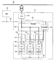
- FIG. 1 is a conceptual configuration diagram for explaining a system configuration according to Embodiment 1 of the present invention.
- a storage battery system 10 shown in FIG. 1 is connected to a power transmission facility 20 of a power system.
- the power system includes power transmission equipment 20, power generation equipment (not shown) connected to the power transmission equipment 20, and load equipment (not shown) connected to the power transmission equipment 20.
- the storage battery system 10 is connected to a remote energy management system (hereinafter referred to as EMS) 30 by a computer network 40.
- the EMS 30 manages the power supply and demand of the power system such as the power generation amount of the power generation facility, the charge / discharge amount of the storage battery system 10, and the power reception amount of the load facility.
- the storage battery system 10 includes an AC / DC converter (hereinafter referred to as PCS) 100, a front battery control station panel (hereinafter referred to as FBCS panel) 120, and a storage battery panel 140.
- PCS AC / DC converter
- FBCS panel front battery control station panel
- storage battery panel 140 storage battery panel 140.
- one FBCS panel 120 is connected to one PCS 100
- a plurality of storage battery panels 140 are connected in parallel to one FBCS panel 120.
- the storage battery panel 140 has three rows, but this is merely an example.
- the number of parallel storage battery panels 140 is determined based on the specifications of the PCS 100. Therefore, the parallel number of the storage battery panels 140 may be one row.
- the storage battery panel 140 includes a fuse 141, a contactor 142, a storage battery module 143, and a storage battery monitoring device (hereinafter referred to as BMU: Battery Management Unit) 144.
- the storage battery module 143 is a module in which a plurality of cells are connected in series. Each cell is a lithium ion battery (LiB).
- the storage battery module 143 is connected to the FBCS panel 120 by a power transmission line via the contactor 142 and the fuse 141.
- the storage battery module 143 is connected to the BMU 144 by a signal line.
- the BMU 144 is connected to the control device 130 on the FBCS board 120 via the computer network 50 and is connected to the contactor 142 via a signal line.
- the BMU 144 monitors the state of the storage battery module 143.
- the BMU 144 includes a current sensor, a voltage sensor, and a temperature sensor as means for measuring the state quantity of the storage battery module 143.
- the current flowing through the storage battery module 143 is measured by the current sensor.
- the voltage of each cell is measured by the voltage sensor.
- the temperature of the storage battery module 143 is measured by the temperature sensor.
- Monitoring of the storage battery module 143 by the BMU 144 is always performed.
- the constant monitoring in the present embodiment is a concept including not only an operation of capturing a continuous signal from a sensor but also an operation of capturing a sensor signal at a predetermined short cycle.
- the BMU 144 transmits storage battery information including information obtained by measurement by each sensor to the control device 130.
- the contactor 142 is disposed between the fuse 141 and the storage battery module 143.
- the contactor 142 receives a closing signal
- the contact is turned on and turned on.
- the contactor 142 receives the opening signal
- the contact is turned OFF and opened.
- the closing signal is a current greater than or equal to a predetermined value [A]
- the release signal is a current less than a predetermined value [A].
- the FBCS panel 120 is connected to the storage battery panel 140 and the PCS 100. Specifically, each storage battery panel 140 is connected to the FBCS panel 120 by an individual power transmission line. The individual transmission lines merge inside the FBCS panel and are connected to a thicker transmission line. The merged power transmission line is connected to the PCS 100.
- the FBCS board 120 includes a control device 130.
- the control device 130 includes, for example, a memory including a ROM and a RAM, an input / output interface that inputs and outputs various types of information, and a processor that can execute various types of arithmetic processing based on the various types of information.
- the control device 130 is connected to the EMS 30 via the computer network 40, to the BMU 144 via the computer network 50, and to the PCS 100 via the computer network 60.
- the control device 130 is connected to the contactor 142 by a signal line.
- the control device 130 plays the role of a command tower that issues a charge / discharge command to the PCS 100.
- the control device 130 receives the charge / discharge request transmitted from the EMS 30 and the storage battery information transmitted from the BMU 144.
- the charge / discharge request includes a request regarding active power and reactive power to be charged / discharged by the PCS 100.
- the charge / discharge request includes a specific request that indicates a specific amount of electric power by a numerical value and an abstract request that requires the charge / discharge power to be maximized.
- the control device 130 determines a charge / discharge command (corresponding to the charge / discharge amount [kW]) for the PCS 100 based on the charge / discharge request and the storage battery information, and transmits it to the PCS 100.
- the control device 130 has a function of safely and maximally controlling the performance and life of the storage battery module 143, a function of outputting a trip command to the PCS 100, a function of turning on and opening the contactor 142, and the like
- the PCS 100 is connected to the power transmission facility 20 by a power transmission line via a transformer.
- the PCS 100 includes a charging function that converts AC power of the power system into DC power and charges the storage battery module 143, and a discharging function that converts DC power of the storage battery module 143 into AC power and discharges it to the power system.
- the amount of electric power charged into the storage battery module 143 and the amount of electric power discharged from the storage battery module 143 are adjusted by the PCS 100.
- the adjustment of the charge / discharge power amount by the PCS 100 is performed according to a charge / discharge instruction supplied from the control device 130.
- the PCS 100 includes a current sensor and a voltage sensor, and the PCS 100 refers to output values of these sensors to adjust the charge / discharge power amount.
- FIG. 2 is a block diagram of a system according to Embodiment 1 of the present invention.
- the block which shows the control apparatus 130 in FIG. 2, some of the various functions with which the control apparatus 130 is provided is represented by the block. Computing resources are allocated to each of these blocks.
- a program corresponding to each block is prepared in the control device 130, and the function of each block is realized in the control device 130 by executing them by a processor.
- the control device 130 has a charge / discharge command function, and the charge / discharge command unit 131 takes charge of the function.
- the control device 130 receives a charge / discharge request from the EMS 30 and receives storage battery information from the BMU 144.
- the charge / discharge command unit 131 determines a charge / discharge command based on the charge / discharge request and the storage battery information, and transmits the charge / discharge command to the PCS 100.
- the charge / discharge command unit 131 calculates chargeable / dischargeable power from the voltage of the storage battery module 143 included in the storage battery information.
- the voltage referred to in the present embodiment means a voltage applied to both ends of the storage battery module 143.
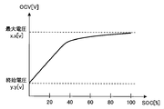
- FIG. 3 is a graph showing the relationship between OCV (closed circuit voltage) and SOC of a lithium ion battery.
- SOC means a charging rate with respect to full charge.
- the lithium ion battery has a characteristic that the voltage is higher as it is fully charged, and the voltage is lower as it is closer to the sky.
- the SOC can be calculated from the measured voltage value, and the chargeable / dischargeable power can be calculated from the SOC.
- the chargeable / dischargeable power calculated by the charge / discharge command unit 131 means the sum of the dischargeable power of all the storage battery modules 143 connected to the PCS 100. This can be calculated from the voltage of the storage battery module 143 and the parallel number.
- the charge / discharge command unit 131 determines a charge / discharge command for the PCS 100 based on a charge / discharge request from the EMS 30 with chargeable / dischargeable power as a constraint. Specifically, in the case where the charge / discharge request is a specific request that specifically specifies the amount of charge power, if the request value of the charge power amount is equal to or less than the chargeable power, the request value is set to the charge / discharge command (charge If the request value for the amount of charge power is greater than the chargeable power, the chargeable power is determined as the charge / discharge command (charge command).
- the charge / discharge request is a specific request that specifically specifies the amount of discharge power
- the required value is determined as a charge / discharge command (discharge command). If the required value of the discharge power amount is larger than the dischargeable power, the dischargeable power is determined as the charge / discharge command (discharge command).
- the charge / discharge request is an abstract request and the maximum charge is required, the chargeable power is determined as the charge / discharge command (charge command), and the discharge is possible when the maximum discharge is required. Electric power is determined as a charge / discharge command (discharge command).
- the chargeable / dischargeable power as the constraint condition is a condition that is preferably satisfied in the determination of the charge / discharge command, but is not a condition that must not be removed. Therefore, if temporary, the charge / discharge command for the PCS 100 can exceed the chargeable / dischargeable power.
- the control device 130 has an overdischarge prevention function, and the overdischarge prevention unit 132 takes charge of the function.
- the overdischarge prevention unit 132 automatically outputs a charge command to the PCS 100 regardless of the charge / discharge request from the EMS 30 so that the storage battery does not reach the overdischarge state.
- the storage battery in the present embodiment means the entire storage battery module 143 connected in parallel, and when the storage battery approaches the overdischarge state, at least one of the cells constituting the storage battery module 143 approaches the overdischarge state.
- the storage battery information supplied from the BMU 144 includes a voltage for each cell.
- the overdischarge prevention unit 132 compares the voltage of each cell with a predetermined lower limit cell voltage, and detects the presence of an overdischarge cell whose voltage is equal to or lower than the lower limit cell voltage, so that the storage battery has approached an overdischarge state. Is detected.
- the overdischarge prevention unit 132 outputs a charge command to the PCS 100 until the voltage of the overdischarge cell recovers and becomes higher than the lower limit cell voltage. At this time, the charge command output by the overdischarge prevention unit 132 has priority over the charge / discharge command determined by the charge / discharge command unit 131 based on the charge / discharge request from the EMS 30.
- the control device 130 has an interlock function, and the interlock processing unit 133 takes charge of the function. Interlocking of the storage battery module 143 is also performed by the BMU 144 when the BMU 144 detects overdischarge, overcharge, temperature abnormality, or the like. However, when these abnormalities occur, the storage battery is already in a considerably overloaded state. Therefore, in the system of the present embodiment, the PCS 100 and the contactor 142 are controlled by software interlock before the interlock by the BMU 144 is executed. When detecting an abnormality in the storage battery system 10, the interlock processing unit 133 performs an interlock process according to the content of the detected abnormality.
- the interlock process is a process of outputting a trip command to the PCS 100 or a process of opening the contactor 142.
- the interlock thresholds such as current, voltage, and temperature are set lower than the thresholds set for the BMU 144.
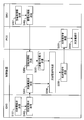
- FIG. 4 is a flowchart of a control routine executed by the storage battery system 10 in order to realize charge / discharge control based on the charge / discharge request from the EMS 30.
- the process of the control device 130 shown in this flowchart is a process realized by the function of the charge / discharge command unit 131.
- a program for executing the processing of the flowchart shown in FIG. 4 is stored in the memory of the control device 130, and the processing shown in FIG. 4 is realized by the processor of the control device 130 reading and executing the program.
- the EMS 30 determines a charge / discharge request for the storage battery system 10 so as to balance the demand and supply of power in the power system (step S101). At this time, the EMS 30 can determine the charge / discharge request without regard to the state of the storage battery system 10, or can determine the charge / discharge request in consideration of the state of the storage battery system 10. However, in the latter case, the period in which the EMS 10 grasps the state of the storage battery system 10 has to be long due to the relationship with the calculation amount borne by the EMS 10. For this reason, the charging / discharging request
- the BMU 144 always acquires storage battery information using the various sensors described above (step S401).
- the storage battery information includes the current flowing through the storage battery module 143, the voltage of each cell, and the temperature of the storage battery module 143. Thereafter, the BMU 144 transmits the acquired storage battery information to the control device 130 (step S402).
- the control device 130 receives the charge / discharge request transmitted from the EMS 30 (step S201). Moreover, the control apparatus 130 receives the storage battery information transmitted from BMU144 (step S202). Control device 130 calculates chargeable / dischargeable power based on the storage battery information received in step S202 (step S203). The chargeable / dischargeable power is recalculated by the control device 130 every time storage battery information is acquired in step S401 and transmitted from the BMU 144 to the control device 130.
- the control device 130 determines a charge / discharge command for the PCS 100 based on the on-site charge / discharge request received in step S201 using the chargeable / dischargeable power calculated in step S203 as a constraint condition (step S204).
- the method for determining the charge / discharge command executed in step S204 is as described in the description of the charge / discharge command function.
- the control device 130 transmits a charge / discharge command to the PCS 100 (step S205).
- the PCS 100 receives the charge / discharge command transmitted from the control device 130 (step S301).
- the PCS 100 performs a charge / discharge operation in accordance with the charge / discharge command (step S302).
- the storage battery system 10 of the present embodiment does not operate the PCS 100 according to the charge / discharge request determined by the EMS 30 as it is.
- Storage battery system 10 of the present embodiment operates PCS 100 in accordance with the charge / discharge command determined by control device 130.
- the determination of the charge / discharge command by the control device 130 not only the charge / discharge request supplied from the EMS 30 but also the storage battery information supplied from the BMU 144 is referred to, and the chargeable / dischargeable power calculated based on the storage battery information is used as a constraint condition. It is done.
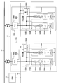
- FIG. 5 is a conceptual configuration diagram for explaining a system configuration according to Embodiment 2 of the present invention.
- the difference between the present embodiment and the first embodiment is in the number of PCS groups included in the storage battery system.
- One PCS group includes one PCS, one FBCS panel connected to the PCS, and one or a plurality of storage battery panels.
- the control device arranged on the FBCS panel is not an element constituting the conceptual PCS group.
- the FBCS panel in the PCS group has a meaning as a panel for connecting a large-capacity transmission line connected to the power system via the PCS and a transmission line extending from each storage battery panel. Since the number of storage battery modules increases as the number of PCS groups included in the storage battery system increases, it can be said that the storage battery system has a large capacity.
- the storage battery system 12 of the present embodiment includes two PCS groups 15A and 15B.
- the first PCS group 15A includes a PCS 100A, an FBCS panel 120A, and a plurality of storage battery panels 140A.
- the second PCS group 15B includes a PCS 100B, an FBCS panel 120B, and a plurality of storage battery panels 140B.
- the configurations of PCS 100A, 100B and storage battery panels 140A, 140B are the same as the configurations of PCS 100 and storage battery panel 140 in the first embodiment.
- the storage battery boards 140A and 140B are provided with fuses 141A and 141B, contactors 142A and 142B, storage battery modules 143A and 143B, and BMUs 144A and 144B, similarly to the storage battery board 140 in the first embodiment.
- the storage battery system 12 of the present embodiment includes a main control device 130A and a sub control device 130B.
- the main control device 130A is disposed on the FBCS panel 120A
- the slave control device 130B is disposed on the FBCS panel 120B.
- the function of the control device 130 in the first embodiment is distributed to the main control device 130A and the sub control device 130B.
- the main control device 130A plays the role of a command tower that issues charge / discharge commands to the PCSs 100A and 100B, and the sub control device 130B operates in accordance with instructions from the main control device 130A.
- the main control device 130A and the sub control device 130B include, for example, a memory including a ROM, a RAM, an input / output interface for inputting / outputting various information, and a processor capable of executing various arithmetic processes based on various information.
- the main control device 130 ⁇ / b> A and the sub control device 130 ⁇ / b> B are connected to the EMS 30 by the computer network 40 and to each other by the computer network 40.
- Main controller 130A is connected to BMU 144A by computer network 50A and to PCS 100A by computer network 60A.
- Main controller 130A is connected to contactor 142A through a signal line.
- the slave control device 130B is connected to the BMU 144B by the computer network 50B and to the PCS 100B by the computer network 60B.
- the slave control device 130B is connected to the contactor 142B by a signal line.
- FIG. 6 is a block diagram of a system according to Embodiment 2 of the present invention.
- the block showing the main control device 130A in FIG. 6 some of various functions of the main control device 130A are represented by blocks.
- the block showing the slave control device 130B some of the various functions provided in the slave control device 130B are represented by blocks.
- a program corresponding to each block is prepared in each of the main control device 130A and the sub control device 130B, and the function of each block is realized by executing them by a processor.
- Main controller 130A has a charge / discharge command function, and charge / discharge command unit 131A takes charge of this function.
- Main controller 130A receives a charge / discharge request from EMS 30, and receives storage battery information related to storage battery module 143A from BMU 144A. Furthermore, main controller 130A receives storage battery information regarding storage battery module 143B received by slave controller 130B from BMU 144B from slave controller 130B.
- the charge / discharge command unit 131A determines a charge / discharge command for each of the PCSs 100A and 100B based on the charge / discharge request and the storage battery information.
- command part 131A transmits charging / discharging instruction
- the charge / discharge command unit 131A calculates chargeable / dischargeable power in the first PCS group 15A from the voltage included in the storage battery information received from the BMU 144A, and calculates the second from the voltage included in the storage battery information received from the slave control device 130B.
- the chargeable / dischargeable power in the PCS group 15B is calculated.
- the charge / discharge command unit 131A matches the charge / discharge power of the PCS groups 15A, 15B to the charge / discharge request from the EMS 30 as much as possible, with the chargeable / dischargeable power calculated for each of the PCS groups 15A, 15B as a constraint.
- the charge / discharge command for each PCS 100A, 100B is determined.
- the chargeable power in the first PCS group 15A is 40 kW and the chargeable power in the second PCS group 15B is 60 kW
- the PCS 100A The charge / discharge command (charge command) is 40 kW
- the charge / discharge command (charge command) for the PCS 100B is 60 kW.
- the charge / discharge command unit 131A calculates the SOC for each PCS group 15A, 15B based on the voltage of each PCS group 15A, 15B.
- the charge / discharge command unit 131A also adjusts the charge / discharge commands for the PCSs 100A and 100B so that the SOC is uniform between the PCS groups 15A and 15B. For example, when the chargeable power in the first PCS group 15A is 40 kW and the chargeable power in the second PCS group 15B is 60 kW, it is assumed that charging of 80 kW of power from the EMS 30 is requested. In this case, the charge / discharge command unit 131A does not set the charge command for each of the PCSs 100A and 100B to 40 kW.
- the charge / discharge command (charge command) for the PCS 100A is 30 kW, Is 50 kW.
- the SOCs of the two PCS groups 15A and 15B can be brought close to the same level.
- the maximum performance of the storage battery can be extracted while suppressing a decrease in the life of the storage battery.
- the determination of the charge / discharge command for each of the PCSs 100A and 100B is performed by the main controller 130A, but not by the slave controller 130B.
- the sub control device 130B only receives the charge / discharge command transmitted from the main control device 130A and transmits it to the PCS 100B. Further, the calculation of the chargeable / dischargeable power is performed by the main control device 130A and is not performed by the sub control device 130B.
- the sub control device 130B only receives the storage battery information necessary for calculating the chargeable / dischargeable power from the BMU 144B and transmits it to the main control device 130A. However, a function corresponding to the charge / discharge command unit 131A is also provided in the slave control device 130B.
- the relationship between the master and the slave is switched, and the slave controller 130B is programmed to work the charge / discharge command function instead of the charge / discharge command unit 131A. Has been.
- Main controller 130A has an overdischarge prevention function, which is overseen by overdischarge prevention unit 132A.
- the overdischarge prevention unit 132A detects that the storage battery of the first PCS group 15A has approached the overdischarge state based on the storage battery information transmitted from the BMU 144, and based on the storage battery information transmitted from the slave control device 130B. It is detected that the storage battery of the second PCS group 15B has approached an overdischarged state.
- overdischarge prevention part 132A outputs a charge command to PCS100A automatically, when detecting that the storage battery has approached the overdischarge state in the 1st PCS group 15A. Further, when it is detected in the second PCS group 15B that the storage battery is approaching an overdischarged state, a charge command is automatically output to the slave control device 130B.
- the details of the overdischarge prevention function are the same as those in the first embodiment.
- the slave control device 130B receives the charge command transmitted from the main control device 130A and transmits it to the PCS 100B. However, a function corresponding to the overdischarge prevention unit 132A is also provided in the slave control device 130B.
- the overdischarge prevention function of the main control device 130A does not work, the relationship between the master and the slave is switched, and the sub control device 130B is programmed so that the overdischarge prevention function works instead of the overdischarge prevention unit 132A. Has been.
- the main control device 130A has an interlock function, and the function is handled by the interlock processing unit 133A.
- the slave control device 130B also has an interlock function, which is handled by the interlock processing unit 133B.
- the interlock processing unit 133A When detecting the abnormality of the first PCS group 15A, the interlock processing unit 133A outputs a trip command to the PCS 100A or opens the contactor 142A according to the detected abnormality.
- the interlock processing unit 133B outputs a trip command to the PCS 100B or opens the contactor 142B in accordance with the detected abnormality. Details of the software interlock by the interlock processing units 133A and 133B are the same as those in the first embodiment.
- FIG. 7 is a flowchart of a control routine executed by the storage battery system 12 in order to realize the charge / discharge control based on the charge / discharge request from the EMS 30.
- the process of main controller 130A shown in this flowchart is a process realized by the function of charge / discharge command unit 131A.
- a program for executing the processing of the flowchart shown in FIG. 7 is stored in the memory of main control device 130A, and the processing shown in FIG. 7 is realized by the processor of main control device 130A reading and executing the program. .
- the EMS 30 determines a charge / discharge request for the storage battery system 12 so as to balance the demand and supply of power in the power system (step S111).
- the EMS 30 transmits the determined charge / discharge request to the main controller 130A (step S112).
- the BMU 144A In the first PCS group 15A, the BMU 144A always acquires storage battery information using various sensors (step S411).
- the storage battery information includes the current flowing through the storage battery module 143A, the voltage of each cell, and the temperature of the storage battery module 143A. Thereafter, the BMU 144A transmits the acquired storage battery information to the main controller 130A (step S412).
- the BMU 144B constantly acquires storage battery information using various sensors (step S711).
- the storage battery information includes the current flowing through the storage battery module 143B, the voltage of each cell, and the temperature of the storage battery module 143B. Thereafter, the BMU 144B transmits the acquired storage battery information to the slave control device 130B (step S712).
- the slave control device 130B receives the storage battery information transmitted from the BMU 144B (step S511). Then, sub control device 130B transmits the received storage battery information to main control device 130A (step S512).
- Main controller 130A receives the charge / discharge request transmitted from EMS 30 (step S211). Further, main controller 130A receives the storage battery information transmitted from BMU 144A of first PCS group 15A (step S212). Main controller 130A calculates chargeable / dischargeable power of first PCS group 15A based on the storage battery information received in step S212 (step S213). This chargeable / dischargeable power is recalculated by main controller 130A every time storage battery information is acquired in step S411 and transmitted from BMU 144A to main controller 130A. Furthermore, main controller 130A receives the storage battery information transmitted from slave controller 130B (step S214).
- Main controller 130A calculates chargeable / dischargeable power of second PCS group 15B based on the storage battery information received in step S214 (step S215). This chargeable / dischargeable power is recalculated by the main control device 130A each time the storage battery information is acquired in step S711 and transmitted from the sub control device 130B to the main control device 130A.
- Main controller 130 ⁇ / b> A charges / discharges PCS 100 ⁇ / b> A and 100 ⁇ / b> B based on the on-site charge / discharge request received in step S ⁇ b> 211, using the chargeable / dischargeable power calculated in step S ⁇ b> 213 and the chargeable / dischargeable power calculated in step S ⁇ b> 215 as constraints.
- a command is determined (step S216). The method for determining the charge / discharge command executed in step S216 is as described in the description of the charge / discharge command function.
- main controller 130A transmits a charge / discharge command for PCS 100A to PCS 100A (step S217). Further, main controller 130A transmits a charge / discharge command for PCS 100B to slave controller 130B (step S218).
- the slave control device 130B receives the charge / discharge command transmitted from the main control device 130A (step S513). Then, slave control device 130B transmits the received charge / discharge command to PCS 100B (step S514).
- the PCS 100A receives the charge / discharge command transmitted from the main controller 130A (step S311).
- the PCS 100A performs a charge / discharge operation according to the charge / discharge command (step S312).
- the PCS 100B receives the charge / discharge command transmitted from the slave control device 130B (step S611).
- the PCS 100B performs a charge / discharge operation in accordance with the charge / discharge command (step S612).
- the storage battery system 12 does not operate the PCSs 100A and 100B as they are according to the charge / discharge request determined by the EMS 30, but according to the charge / discharge command determined by the main controller 130A.
- the PCSs 100A and 100B are operated.
- the charge / discharge power of the entire PCS group 15A, 15B matches the charge / discharge request, and the SOC is uniform between the PCS groups 15A, 15B.
- Charge / discharge commands for the PCSs 100A and 100B are determined for each of the PCS groups 15A and 15B. For this reason, according to the storage battery system 12 of this Embodiment, the maximum performance of a storage battery can be pulled out without forcing an unreasonable driving
- the present invention is not limited to the above-described embodiment, and various modifications can be made without departing from the spirit of the present invention.
- the number of PCS groups can be increased in the second embodiment.
- the added PCS group may be provided with a slave control device having the same function as the slave control device 130B.
- control devices 130, 130A, 130B are arranged on the FBCS boards 120, 120A, 120B, but the arrangement positions of the control devices 130, 130A, 130B are limited to this. It is not something. For example, it is good also as arrange
- various functions mounted on the control devices 130, 130A, and 130B may be mounted on the PCSs 100, 100A, and 100B, and the PCSs 100, 100A, and 100B may be mounted with the various functions. The same applies to the storage battery panels 140, 140A, 140B and BMU 144, 144A, 144B.
Landscapes
- Engineering & Computer Science (AREA)
- Power Engineering (AREA)
- Supply And Distribution Of Alternating Current (AREA)
- Charge And Discharge Circuits For Batteries Or The Like (AREA)
- Remote Monitoring And Control Of Power-Distribution Networks (AREA)
Abstract
Description
[実施の形態1の全体構成]
図1は、本発明の実施の形態1に係るシステム構成を説明するための概念構成図である。図1に示す蓄電池システム10は、電力系統の送電設備20に接続される。電力系統には、送電設備20の他、送電設備20に接続された発電設備(図示省略)、送電設備20に接続された負荷設備(図示省略)が含まれる。蓄電池システム10は、コンピュータネットワーク40により遠方のエネルギマネジメントシステム(以下、EMS)30に接続される。EMS30は、発電設備の発電量、蓄電池システム10の充放電量、負荷設備の受電量など、電力系統の電力需給を管理する。
蓄電池盤140は、ヒューズ141、コンタクタ142、蓄電池モジュール143、及び蓄電池監視装置(以下、BMU:Battery Management Unit)144を備える。蓄電池モジュール143は、複数のセルが直列に接続されたモジュールである。各セルは、リチウムイオン電池(LiB)である。蓄電池モジュール143は、コンタクタ142及びヒューズ141を介して送電線によりFBCS盤120に接続される。また、蓄電池モジュール143は、信号線によりBMU144に接続される。BMU144は、コンピュータネットワーク50によりFBCS盤120上の制御装置130に接続され、信号線によりコンタクタ142に接続される。
FBCS盤120は、蓄電池盤140とPCS100とに接続される。具体的には、各蓄電池盤140は、個別の送電線によりFBCS盤120に接続される。個別の送電線はFBCS盤の内部で合流し、より太い送電線に接続される。合流後の送電線はPCS100に接続される。また、FBCS盤120は制御装置130を備える。制御装置130は、例えばROM、RAM等を含むメモリ、各種情報を入出力する入出力インタフェース、各種情報に基づいて各種演算処理を実行可能なプロセッサを備える。制御装置130は、コンピュータネットワーク40によりEMS30に、コンピュータネットワーク50によりBMU144に、コンピュータネットワーク60によりPCS100に接続される。また、制御装置130は、信号線によりコンタクタ142に接続される。
PCS100は、変圧器を介して送電線により送電設備20に接続される。PCS100は、電力系統の交流電力を直流電力に変換して蓄電池モジュール143に充電する充電機能と、蓄電池モジュール143の直流電力を交流電力に変換して電力系統に放電する放電機能とを備える。蓄電池モジュール143への充電電力量、及び蓄電池モジュール143からの放電電力量は、PCS100によって調整される。PCS100による充放電電力量の調整は、制御装置130から供給される充放電指示に従って行われる。PCS100は電流センサと電圧センサとを備え、PCS100はこれらのセンサの出力値を参照して充放電電力量の調整を実施する。
図2は、本発明の実施の形態1に係るシステムのブロック図である。図2における制御装置130を示すブロック内には、制御装置130が備える種々の機能のうちの一部がブロックで表されている。これらブロックのそれぞれに演算資源が割り当てられている。制御装置130には各ブロックに対応するプログラムが用意され、それらがプロセッサによって実行されることで各ブロックの機能が制御装置130において実現される。
制御装置130は充放電指令機能を有し、その機能は充放電指令部131が受け持つ。制御装置130は、EMS30から充放電要求を受信し、BMU144から蓄電池情報を受信する。充放電指令部131は、充放電要求と蓄電池情報とに基づいて充放電指令を決定し、充放電指令をPCS100に送信する。
制御装置130は過放電防止機能を有し、その機能は過放電防止部132が受け持つ。過放電防止部132は、蓄電池が過放電状態に近づいたときには、蓄電池が過放電状態に至らないように、EMS30からの充放電要求とは無関係にPCS100に対して自動的に充電指令を出力する。本実施の形態でいう蓄電池とは、並列接続された蓄電池モジュール143の全体を意味し、蓄電池が過放電状態に近づくとは、蓄電池モジュール143を構成するセルの少なくとも1つが過放電状態に近づくことを意味する。BMU144から供給される蓄電池情報にはセルごとの電圧が含まれている。過放電防止部132は、各セルの電圧を所定の下限セル電圧と比較し、電圧が下限セル電圧以下になっている過放電セルの存在を検知することによって蓄電池が過放電状態に近づいたことを検知する。過放電防止部132は、過放電セルの電圧が回復して下限セル電圧よりも高くなるまで、PCS100に対して充電指令を出力する。このとき過放電防止部132が出力する充電指令は、充放電指令部131においてEMS30からの充放電要求に基づき決定される充放電指令に優先する。
また、制御装置130はインターロック機能を有し、その機能はインターロック処理部133が受け持つ。蓄電池モジュール143のインターロックは、BMU144が過放電、過充電、温度異常等を検出した場合に、BMU144によっても行われる。しかし、これらの異常が発生したときには、蓄電池は既にかなりの過負荷状態になっている。そこで、本実施の形態のシステムでは、BMU144によるインターロックが実行される前に、ソフトウェアインターロックによりPCS100、コンタクタ142を制御する。インターロック処理部133は、蓄電池システム10の異常を検知した場合に、検知した異常の内容に応じたインターロック処理を施す。具体的には、インターロック処理は、PCS100へトリップ指令を出力する処理や、コンタクタ142を開放させる処理である。なお、BMU144に先駆けてインターロック処理を実行するために、電流、電圧、温度等のインターロック閾値は、BMU144に設定された閾値よりも低く設定されている。
図4は、EMS30からの充放電要求に基づく充放電制御を実現するために、蓄電池システム10が実行する制御ルーチンのフローチャートである。このフローチャートに示す制御装置130の処理は、充放電指令部131の機能によって実現される処理である。制御装置130のメモリには、図4に示すフローチャートの処理を実行するプログラムが記憶されており、制御装置130のプロセッサがプログラムを読み出して、実行することにより図4示す処理が実現される。
[実施の形態2の全体構成]
図5は、本発明の実施の形態2に係るシステム構成を説明するための概念構成図である。本実施の形態と実施の形態1との相違点は、蓄電池システムに含まれるPCSグループの数にある。1つのPCSグループは、1つのPCSと、そのPCSに接続される1つのFBCS盤と1又は複数の蓄電池盤とから構成される。ただし、FBCS盤に配置される制御装置は、概念としてのPCSグループを構成する要素ではない。PCSグループにおけるFBCS盤は、PCSを経由して電力系統につながる容量の大きい送電線と、それぞれの蓄電池盤から延びる送電線とを接続するための盤としての意味を持つ。蓄電池システムに含まれるPCSグループの数が多いほど、蓄電池モジュールの数も多くなることから、その蓄電池システムは大容量であると言える。
図6は、本発明の実施の形態2に係るシステムのブロック図である。図6における主制御装置130Aを示すブロック内には、主制御装置130Aが備える種々の機能のうちの一部がブロックで表されている。また、従制御装置130Bを示すブロック内には、従制御装置130Bが備える種々の機能のうちの一部がブロックで表されている。主制御装置130Aと従制御装置130Bのそれぞれには各ブロックに対応するプログラムが用意され、それらがプロセッサによって実行されることで各ブロックの機能が実現される。
主制御装置130Aは充放電指令機能を有し、その機能は充放電指令部131Aが受け持つ。主制御装置130Aは、EMS30から充放電要求を受信し、BMU144Aから蓄電池モジュール143Aに関する蓄電池情報を受信する。さらに、主制御装置130Aは、従制御装置130BがBMU144Bから受信した蓄電池モジュール143Bに関する蓄電池情報を従制御装置130Bから受信する。充放電指令部131Aは、充放電要求と蓄電池情報とに基づいて各PCS100A,100Bに対する充放電指令を決定する。そして、充放電指令部131Aは、PCS100Aに対して充放電指令を送信するとともに、PCS100Bに対する充放電指令を従制御装置130Bに送信する。
主制御装置130Aは過放電防止機能を有し、その機能は過放電防止部132Aが受け持つ。過放電防止部132Aは、BMU144から送信される蓄電池情報に基づいて第1のPCSグループ15Aの蓄電池が過放電状態に近づいたことを検知し、従制御装置130Bから送信される蓄電池情報に基づいて第2のPCSグループ15Bの蓄電池が過放電状態に近づいたことを検知する。そして、過放電防止部132Aは、第1のPCSグループ15Aにおいて蓄電池が過放電状態に近づいたことを検知したときには、PCS100Aに対して自動的に充電指令を出力する。また、第2のPCSグループ15Bにおいて蓄電池が過放電状態に近づいたことを検知したときには、従制御装置130Bに対して自動的に充電指令を出力する。過放電防止機能の詳細は実施の形態1と共通する内容になっている。
主制御装置130Aはインターロック機能を有し、その機能はインターロック処理部133Aが受け持つ。また、従制御装置130Bもインターロック機能を有し、その機能はインターロック処理部133Bが受け持つ。インターロック処理部133Aは、第1のPCSグループ15Aの異常を検知した場合に、検知した異常の内容に応じてPCS100Aへトリップ指令を出力したり、コンタクタ142Aを開放させたりする。インターロック処理部133Bは、第2のPCSグループ15Bの異常を検知した場合に、検知した異常の内容に応じてPCS100Bへトリップ指令を出力したり、コンタクタ142Bを開放させたりする。各インターロック処理部133A,133Bによるソフトウェアインターロックの詳細は実施の形態1と共通する内容になっている。
図7は、EMS30からの充放電要求に基づく充放電制御を実現するために、蓄電池システム12が実行する制御ルーチンのフローチャートである。このフローチャートに示す主制御装置130Aの処理は、充放電指令部131Aの機能によって実現される処理である。主制御装置130Aのメモリには、図7に示すフローチャートの処理を実行するプログラムが記憶されており、主制御装置130Aのプロセッサがプログラムを読み出して、実行することにより図7示す処理が実現される。
本発明は上述の実施の形態に限定されるものではなく、本発明の趣旨を逸脱しない範囲で種々変形して実施することができる。例えば、実施の形態2においてPCSグループの数を増やすこともできる。増設したPCSグループには、従制御装置130Bと同機能の従制御装置を備えればよい。
15A,15B PCSグループ
20 送電設備
30 エネルギマネジメントシステム(EMS)
40,50,50A,50B,60,60A,60B コンピュータネットワーク
100,100A,100B 交直変換装置(PCS)
120,120A,120B FBCS盤
130 制御装置
130A 主制御装置
130B 従制御装置
131,131A 充放電指令部
132,132A 過放電防止部
133,133A,133B インターロック処理部
140,140A,140B 蓄電池盤
141,141A,141B ヒューズ
142,142A,142B コンタクタ
143,143A,143B 蓄電池モジュール
144,144A,144B 蓄電池監視装置(BMU)
Claims (12)
- 電力系統に接続される蓄電池システムであって、前記電力系統の電力需給を管理するエネルギマネジメントシステムからの充放電要求に基づいて動作する蓄電池システムにおいて、
蓄電池と、
前記蓄電池の状態を監視する蓄電池監視装置と、
前記電力系統の交流電力を直流電力に変換して前記蓄電池に充電する機能と、前記蓄電池の直流電力を交流電力に変換して前記電力系統に放電する機能とを有する交直変換装置と、
前記充放電要求と前記蓄電池監視装置から供給される蓄電池情報とを受信し、前記充放電要求と前記蓄電池情報とに基づいて前記交直変換装置を制御する制御装置と、を備え、
前記制御装置は、
前記蓄電池情報に基づいて充放電可能電力を計算し、前記充放電可能電力を制約条件として、前記充放電要求に基づき前記交直変換装置に対する充放電指令を決定する充放電指令部を備える
ことを特徴とする蓄電池システム。 - 前記制御装置は、前記蓄電池システムの異常を検知した場合に、検知した異常の内容に応じたインターロック処理を施すインターロック処理部をさらに備える
ことを特徴とする請求項1に記載の蓄電池システム。 - 前記インターロック処理部は、前記蓄電池情報から前記蓄電池システムの異常を検知するように構成されている
ことを特徴とする請求項2に記載の蓄電池システム。 - 前記充放電指令部は、前記蓄電池の電圧から前記充放電可能電力を計算するように構成されている
ことを特徴とする請求項1乃至3の何れか1項に記載の蓄電池システム。 - 前記蓄電池は、複数の蓄電池セルが直列に接続されてなる蓄電池モジュールが複数並列に接続されてなり、
前記充放電指令部は、前記蓄電池の電圧と前記蓄電池モジュールの並列数とから前記充放電可能電力を計算するように構成されている
ことを特徴とする請求項1乃至3の何れか1項に記載の蓄電池システム。 - 前記充放電指令部は、前記蓄電池の充放電電力が最大になるように前記充放電指令を決定するように構成されている
ことを特徴とする請求項1乃至5の何れか1項に記載の蓄電池システム。 - 1つの前記交直変換装置に1又は複数の前記蓄電池及び前記蓄電池監視装置が割り当てられることにより1つのPCSグループが構成され、
複数の前記PCSグループに対して1つの前記制御装置が割り当てられ、
前記充放電指令部は、前記PCSグループごとに計算される前記充放電可能電力に合わせて、前記充放電指令を前記PCSグループごとに決定するように構成されている
ことを特徴とする請求項1乃至6の何れか1項に記載の蓄電池システム。 - 前記充放電指令部は、複数の前記PCSグループの全体の充放電電力が前記充放電要求に合致するように、前記充放電指令を前記PCSグループ間で調整するように構成されている
ことを特徴とする請求項7に記載の蓄電池システム。 - 前記充放電指令部は、前記PCSグループごとにSOCを計算し、前記PCSグループ間でSOCが均一になるように、前記充放電指令を前記PCSグループごとに決定するように構成されている
ことを特徴とする請求項7又は8に記載の蓄電池システム。 - 前記制御装置は、
前記蓄電池が過放電状態に近づいたときには、前記蓄電池が過放電状態に至らないように、前記充放電要求とは無関係に前記交直変換装置に対して自動的に充電指令を出力する過放電防止部をさらに備える
ことを特徴とする請求項1乃至9の何れか1項に記載の蓄電池システム。 - 前記過放電防止部は、前記蓄電池の電圧を所定の下限電圧と比較し、前記蓄電池の電圧が前記下限電圧以下になったことによって前記蓄電池が過放電状態に近づいたことを検知するように構成されている
ことを特徴とする請求項10に記載の蓄電池システム。 - 前記蓄電池は、複数の蓄電池セルが直列に接続されてなる蓄電池モジュールが複数並列に接続されてなり、
前記過放電防止部は、前記蓄電池セルのそれぞれの電圧を所定の下限セル電圧と比較し、前記蓄電池セルの何れか1つの電圧が前記下限セル電圧以下になったことによって前記蓄電池が過放電状態に近づいたことを検知するように構成されている
ことを特徴とする請求項10に記載の蓄電池システム。
Priority Applications (4)
| Application Number | Priority Date | Filing Date | Title |
|---|---|---|---|
| CN201380079661.1A CN105556782B (zh) | 2013-09-19 | 2013-09-19 | 蓄电池系统 |
| JP2015537510A JP6384482B2 (ja) | 2013-09-19 | 2013-09-19 | 蓄電池システム |
| US14/914,195 US10044200B2 (en) | 2013-09-19 | 2013-09-19 | Storage battery system |
| PCT/JP2013/075345 WO2015040724A1 (ja) | 2013-09-19 | 2013-09-19 | 蓄電池システム |
Applications Claiming Priority (1)
| Application Number | Priority Date | Filing Date | Title |
|---|---|---|---|
| PCT/JP2013/075345 WO2015040724A1 (ja) | 2013-09-19 | 2013-09-19 | 蓄電池システム |
Publications (1)
| Publication Number | Publication Date |
|---|---|
| WO2015040724A1 true WO2015040724A1 (ja) | 2015-03-26 |
Family
ID=52688406
Family Applications (1)
| Application Number | Title | Priority Date | Filing Date |
|---|---|---|---|
| PCT/JP2013/075345 Ceased WO2015040724A1 (ja) | 2013-09-19 | 2013-09-19 | 蓄電池システム |
Country Status (4)
| Country | Link |
|---|---|
| US (1) | US10044200B2 (ja) |
| JP (1) | JP6384482B2 (ja) |
| CN (1) | CN105556782B (ja) |
| WO (1) | WO2015040724A1 (ja) |
Cited By (9)
| Publication number | Priority date | Publication date | Assignee | Title |
|---|---|---|---|---|
| JP2017011938A (ja) * | 2015-06-24 | 2017-01-12 | 株式会社東芝 | グリッド制御装置、グリッド制御システム及びグリッド制御プログラム |
| JP2017017820A (ja) * | 2015-06-30 | 2017-01-19 | 株式会社東芝 | 蓄電池管理システム |
| JP2017034983A (ja) * | 2015-07-28 | 2017-02-09 | エルエス産電株式会社Lsis Co., Ltd. | エネルギー管理システム |
| JP2017153288A (ja) * | 2016-02-25 | 2017-08-31 | オムロン株式会社 | 蓄電制御装置、蓄電制御方法、および蓄電制御プログラム |
| EP3439132A4 (en) * | 2016-03-30 | 2019-03-13 | SANYO Electric Co., Ltd. | POWER SUPPLY SYSTEM, CONTROL SYSTEM AND POWER SUPPLY METHOD FOR POWER SUPPLY SYSTEM |
| JPWO2022195777A1 (ja) * | 2021-03-17 | 2022-09-22 | ||
| JP2023030830A (ja) * | 2021-08-24 | 2023-03-08 | トヨタ自動車株式会社 | 電源システム |
| JP2023525301A (ja) * | 2020-07-22 | 2023-06-15 | エルジー エナジー ソリューション リミテッド | デュアルバッテリーにおけるバッテリー間の充放電制御システム及び方法 |
| WO2026070123A1 (ja) * | 2024-09-25 | 2026-04-02 | パナソニックIpマネジメント株式会社 | 蓄電システム、放電制御方法、および放電制御プログラム |
Families Citing this family (6)
| Publication number | Priority date | Publication date | Assignee | Title |
|---|---|---|---|---|
| JP6384482B2 (ja) * | 2013-09-19 | 2018-09-05 | 東芝三菱電機産業システム株式会社 | 蓄電池システム |
| JP6384483B2 (ja) * | 2013-09-19 | 2018-09-05 | 東芝三菱電機産業システム株式会社 | 蓄電池システム |
| CN106451512A (zh) * | 2016-11-25 | 2017-02-22 | 国网上海市电力公司 | 一种用于钠硫电池储能系统的自动运行控制方法及装置 |
| JP7452273B2 (ja) * | 2020-06-12 | 2024-03-19 | トヨタ自動車株式会社 | 電池システム |
| WO2022019664A1 (ko) * | 2020-07-21 | 2022-01-27 | 주식회사 엘지에너지솔루션 | 병렬 멀티 팩 모듈의 출력 제어 장치 및 방법 |
| CN112952883B (zh) * | 2021-04-22 | 2023-02-07 | 国网甘肃省电力公司电力科学研究院 | 一种分布式储能系统的充电控制方法及系统 |
Citations (5)
| Publication number | Priority date | Publication date | Assignee | Title |
|---|---|---|---|---|
| JP2001224142A (ja) * | 2000-02-08 | 2001-08-17 | Nissin Electric Co Ltd | 太陽光発電装置 |
| JP2003169421A (ja) * | 2001-12-03 | 2003-06-13 | Mitsubishi Heavy Ind Ltd | 電力貯蔵システム及びその制御方法 |
| WO2009084673A1 (ja) * | 2007-12-28 | 2009-07-09 | Sumitomo Heavy Industries, Ltd. | ハイブリッド式建設機械 |
| JP2013169068A (ja) * | 2012-02-15 | 2013-08-29 | Sanyo Electric Co Ltd | 電力制御システム |
| JP2013172567A (ja) * | 2012-02-21 | 2013-09-02 | Mitsubishi Heavy Ind Ltd | 電力制御装置および電力制御方法 |
Family Cites Families (11)
| Publication number | Priority date | Publication date | Assignee | Title |
|---|---|---|---|---|
| EP2189859A1 (de) * | 2008-11-21 | 2010-05-26 | SMA Solar Technology AG | Energieerzeungsanlage mit mehreren Stromgeneratoren mit mehreren Umrichtern, z.B. PV- und/oder Windkraftanlagen |
| JP5271329B2 (ja) | 2010-09-28 | 2013-08-21 | 株式会社東芝 | 蓄電池管理システム |
| JP2012175864A (ja) * | 2011-02-23 | 2012-09-10 | Sanyo Electric Co Ltd | 蓄電システム |
| JP5677161B2 (ja) * | 2011-03-28 | 2015-02-25 | 株式会社東芝 | 充放電判定装置及びプログラム |
| JP5802463B2 (ja) | 2011-07-22 | 2015-10-28 | 株式会社東芝 | 電気量調整装置、電気量調整方法、電気量調整プログラム及び電力供給システム |
| WO2013038483A1 (ja) | 2011-09-13 | 2013-03-21 | 東芝三菱電機産業システム株式会社 | ピークカットシステム |
| JP5364768B2 (ja) | 2011-09-26 | 2013-12-11 | 株式会社東芝 | 電力需給スケジューリング装置 |
| JP5701730B2 (ja) * | 2011-09-30 | 2015-04-15 | 株式会社東芝 | 充放電判定装置、充放電判定方法、及び充放電判定プログラム |
| WO2015040721A1 (ja) * | 2013-09-19 | 2015-03-26 | 東芝三菱電機産業システム株式会社 | 蓄電池システム |
| JP6384483B2 (ja) * | 2013-09-19 | 2018-09-05 | 東芝三菱電機産業システム株式会社 | 蓄電池システム |
| JP6384482B2 (ja) * | 2013-09-19 | 2018-09-05 | 東芝三菱電機産業システム株式会社 | 蓄電池システム |
-
2013
- 2013-09-19 JP JP2015537510A patent/JP6384482B2/ja active Active
- 2013-09-19 WO PCT/JP2013/075345 patent/WO2015040724A1/ja not_active Ceased
- 2013-09-19 US US14/914,195 patent/US10044200B2/en active Active
- 2013-09-19 CN CN201380079661.1A patent/CN105556782B/zh active Active
Patent Citations (5)
| Publication number | Priority date | Publication date | Assignee | Title |
|---|---|---|---|---|
| JP2001224142A (ja) * | 2000-02-08 | 2001-08-17 | Nissin Electric Co Ltd | 太陽光発電装置 |
| JP2003169421A (ja) * | 2001-12-03 | 2003-06-13 | Mitsubishi Heavy Ind Ltd | 電力貯蔵システム及びその制御方法 |
| WO2009084673A1 (ja) * | 2007-12-28 | 2009-07-09 | Sumitomo Heavy Industries, Ltd. | ハイブリッド式建設機械 |
| JP2013169068A (ja) * | 2012-02-15 | 2013-08-29 | Sanyo Electric Co Ltd | 電力制御システム |
| JP2013172567A (ja) * | 2012-02-21 | 2013-09-02 | Mitsubishi Heavy Ind Ltd | 電力制御装置および電力制御方法 |
Cited By (17)
| Publication number | Priority date | Publication date | Assignee | Title |
|---|---|---|---|---|
| JP2017011938A (ja) * | 2015-06-24 | 2017-01-12 | 株式会社東芝 | グリッド制御装置、グリッド制御システム及びグリッド制御プログラム |
| JP2017017820A (ja) * | 2015-06-30 | 2017-01-19 | 株式会社東芝 | 蓄電池管理システム |
| JP2017034983A (ja) * | 2015-07-28 | 2017-02-09 | エルエス産電株式会社Lsis Co., Ltd. | エネルギー管理システム |
| US10424945B2 (en) | 2015-07-28 | 2019-09-24 | Lsis Co., Ltd. | Energy storage management system |
| JP2017153288A (ja) * | 2016-02-25 | 2017-08-31 | オムロン株式会社 | 蓄電制御装置、蓄電制御方法、および蓄電制御プログラム |
| US10714940B2 (en) | 2016-02-25 | 2020-07-14 | Omron Corporation | Power storage control apparatus and power storage control method |
| EP3439132A4 (en) * | 2016-03-30 | 2019-03-13 | SANYO Electric Co., Ltd. | POWER SUPPLY SYSTEM, CONTROL SYSTEM AND POWER SUPPLY METHOD FOR POWER SUPPLY SYSTEM |
| JP7504227B2 (ja) | 2020-07-22 | 2024-06-21 | エルジー エナジー ソリューション リミテッド | デュアルバッテリーにおけるバッテリー間の充放電制御システム及び方法 |
| JP2023525301A (ja) * | 2020-07-22 | 2023-06-15 | エルジー エナジー ソリューション リミテッド | デュアルバッテリーにおけるバッテリー間の充放電制御システム及び方法 |
| WO2022195777A1 (ja) * | 2021-03-17 | 2022-09-22 | 株式会社東芝 | 蓄電池管理装置、蓄電池管理方法、および、プログラム |
| JPWO2022195777A1 (ja) * | 2021-03-17 | 2022-09-22 | ||
| AU2021434172A9 (en) * | 2021-03-17 | 2024-07-11 | Kabushiki Kaisha Toshiba | Storage battery management device, storage battery management method, and program |
| AU2021434172B2 (en) * | 2021-03-17 | 2024-10-24 | Kabushiki Kaisha Toshiba | Storage battery management device, storage battery management method, and program |
| JP7615300B2 (ja) | 2021-03-17 | 2025-01-16 | 株式会社東芝 | 蓄電池管理装置、蓄電池管理方法、および、プログラム |
| JP2023030830A (ja) * | 2021-08-24 | 2023-03-08 | トヨタ自動車株式会社 | 電源システム |
| JP7464019B2 (ja) | 2021-08-24 | 2024-04-09 | トヨタ自動車株式会社 | 電源システム |
| WO2026070123A1 (ja) * | 2024-09-25 | 2026-04-02 | パナソニックIpマネジメント株式会社 | 蓄電システム、放電制御方法、および放電制御プログラム |
Also Published As
| Publication number | Publication date |
|---|---|
| JP6384482B2 (ja) | 2018-09-05 |
| JPWO2015040724A1 (ja) | 2017-03-02 |
| US20160211681A1 (en) | 2016-07-21 |
| CN105556782A (zh) | 2016-05-04 |
| US10044200B2 (en) | 2018-08-07 |
| CN105556782B (zh) | 2018-09-18 |
Similar Documents
| Publication | Publication Date | Title |
|---|---|---|
| JP6384482B2 (ja) | 蓄電池システム | |
| JP6384483B2 (ja) | 蓄電池システム | |
| JP5896096B1 (ja) | 発電設備および発電制御装置 | |
| JP6249022B2 (ja) | 蓄電池システム | |
| JP6327356B2 (ja) | 蓄電池システム | |
| CN107078514B (zh) | 蓄电池系统 | |
| WO2015040723A1 (ja) | 蓄電池システム | |
| JP6288096B2 (ja) | 蓄電池システム | |
| JP6481694B2 (ja) | 蓄電池容量測定装置 | |
| WO2016063351A1 (ja) | 充放電管理装置 | |
| EP3358646B1 (en) | Systems and methods of comissioning energy storage systems (ess) | |
| CN112952928A (zh) | 蓄电池系统 | |
| WO2025041752A1 (ja) | 蓄電システム及び充放電の制御方法 |
Legal Events
| Date | Code | Title | Description |
|---|---|---|---|
| WWE | Wipo information: entry into national phase |
Ref document number: 201380079661.1 Country of ref document: CN |
|
| 121 | Ep: the epo has been informed by wipo that ep was designated in this application |
Ref document number: 13893724 Country of ref document: EP Kind code of ref document: A1 |
|
| ENP | Entry into the national phase |
Ref document number: 2015537510 Country of ref document: JP Kind code of ref document: A |
|
| WWE | Wipo information: entry into national phase |
Ref document number: 14914195 Country of ref document: US |
|
| NENP | Non-entry into the national phase |
Ref country code: DE |
|
| 122 | Ep: pct application non-entry in european phase |
Ref document number: 13893724 Country of ref document: EP Kind code of ref document: A1 |