WO2015033969A1 - 磁気スケール付き運動案内装置 - Google Patents
磁気スケール付き運動案内装置 Download PDFInfo
- Publication number
- WO2015033969A1 WO2015033969A1 PCT/JP2014/073225 JP2014073225W WO2015033969A1 WO 2015033969 A1 WO2015033969 A1 WO 2015033969A1 JP 2014073225 W JP2014073225 W JP 2014073225W WO 2015033969 A1 WO2015033969 A1 WO 2015033969A1
- Authority
- WO
- WIPO (PCT)
- Prior art keywords
- magnetic scale
- track rail
- groove
- magnetic
- scale
- Prior art date
- Legal status (The legal status is an assumption and is not a legal conclusion. Google has not performed a legal analysis and makes no representation as to the accuracy of the status listed.)
- Ceased
Links
Images





Classifications
-
- F—MECHANICAL ENGINEERING; LIGHTING; HEATING; WEAPONS; BLASTING
- F16—ENGINEERING ELEMENTS AND UNITS; GENERAL MEASURES FOR PRODUCING AND MAINTAINING EFFECTIVE FUNCTIONING OF MACHINES OR INSTALLATIONS; THERMAL INSULATION IN GENERAL
- F16C—SHAFTS; FLEXIBLE SHAFTS; ELEMENTS OR CRANKSHAFT MECHANISMS; ROTARY BODIES OTHER THAN GEARING ELEMENTS; BEARINGS
- F16C41/00—Other accessories, e.g. devices integrated in the bearing not relating to the bearing function as such
- F16C41/007—Encoders, e.g. parts with a plurality of alternating magnetic poles
-
- F—MECHANICAL ENGINEERING; LIGHTING; HEATING; WEAPONS; BLASTING
- F16—ENGINEERING ELEMENTS AND UNITS; GENERAL MEASURES FOR PRODUCING AND MAINTAINING EFFECTIVE FUNCTIONING OF MACHINES OR INSTALLATIONS; THERMAL INSULATION IN GENERAL
- F16C—SHAFTS; FLEXIBLE SHAFTS; ELEMENTS OR CRANKSHAFT MECHANISMS; ROTARY BODIES OTHER THAN GEARING ELEMENTS; BEARINGS
- F16C29/00—Bearings for parts moving only linearly
- F16C29/005—Guide rails or tracks for a linear bearing, i.e. adapted for movement of a carriage or bearing body there along
-
- F—MECHANICAL ENGINEERING; LIGHTING; HEATING; WEAPONS; BLASTING
- F16—ENGINEERING ELEMENTS AND UNITS; GENERAL MEASURES FOR PRODUCING AND MAINTAINING EFFECTIVE FUNCTIONING OF MACHINES OR INSTALLATIONS; THERMAL INSULATION IN GENERAL
- F16C—SHAFTS; FLEXIBLE SHAFTS; ELEMENTS OR CRANKSHAFT MECHANISMS; ROTARY BODIES OTHER THAN GEARING ELEMENTS; BEARINGS
- F16C29/00—Bearings for parts moving only linearly
- F16C29/04—Ball or roller bearings
- F16C29/06—Ball or roller bearings in which the rolling bodies circulate partly without carrying load
-
- F—MECHANICAL ENGINEERING; LIGHTING; HEATING; WEAPONS; BLASTING
- F16—ENGINEERING ELEMENTS AND UNITS; GENERAL MEASURES FOR PRODUCING AND MAINTAINING EFFECTIVE FUNCTIONING OF MACHINES OR INSTALLATIONS; THERMAL INSULATION IN GENERAL
- F16C—SHAFTS; FLEXIBLE SHAFTS; ELEMENTS OR CRANKSHAFT MECHANISMS; ROTARY BODIES OTHER THAN GEARING ELEMENTS; BEARINGS
- F16C29/00—Bearings for parts moving only linearly
- F16C29/04—Ball or roller bearings
- F16C29/06—Ball or roller bearings in which the rolling bodies circulate partly without carrying load
- F16C29/0602—Details of the bearing body or carriage or parts thereof, e.g. methods for manufacturing or assembly
-
- F—MECHANICAL ENGINEERING; LIGHTING; HEATING; WEAPONS; BLASTING
- F16—ENGINEERING ELEMENTS AND UNITS; GENERAL MEASURES FOR PRODUCING AND MAINTAINING EFFECTIVE FUNCTIONING OF MACHINES OR INSTALLATIONS; THERMAL INSULATION IN GENERAL
- F16C—SHAFTS; FLEXIBLE SHAFTS; ELEMENTS OR CRANKSHAFT MECHANISMS; ROTARY BODIES OTHER THAN GEARING ELEMENTS; BEARINGS
- F16C29/00—Bearings for parts moving only linearly
- F16C29/08—Arrangements for covering or protecting the ways
-
- F—MECHANICAL ENGINEERING; LIGHTING; HEATING; WEAPONS; BLASTING
- F16—ENGINEERING ELEMENTS AND UNITS; GENERAL MEASURES FOR PRODUCING AND MAINTAINING EFFECTIVE FUNCTIONING OF MACHINES OR INSTALLATIONS; THERMAL INSULATION IN GENERAL
- F16C—SHAFTS; FLEXIBLE SHAFTS; ELEMENTS OR CRANKSHAFT MECHANISMS; ROTARY BODIES OTHER THAN GEARING ELEMENTS; BEARINGS
- F16C29/00—Bearings for parts moving only linearly
- F16C29/08—Arrangements for covering or protecting the ways
- F16C29/082—Arrangements for covering or protecting the ways fixed to the way
-
- F—MECHANICAL ENGINEERING; LIGHTING; HEATING; WEAPONS; BLASTING
- F16—ENGINEERING ELEMENTS AND UNITS; GENERAL MEASURES FOR PRODUCING AND MAINTAINING EFFECTIVE FUNCTIONING OF MACHINES OR INSTALLATIONS; THERMAL INSULATION IN GENERAL
- F16C—SHAFTS; FLEXIBLE SHAFTS; ELEMENTS OR CRANKSHAFT MECHANISMS; ROTARY BODIES OTHER THAN GEARING ELEMENTS; BEARINGS
- F16C41/00—Other accessories, e.g. devices integrated in the bearing not relating to the bearing function as such
-
- F—MECHANICAL ENGINEERING; LIGHTING; HEATING; WEAPONS; BLASTING
- F16—ENGINEERING ELEMENTS AND UNITS; GENERAL MEASURES FOR PRODUCING AND MAINTAINING EFFECTIVE FUNCTIONING OF MACHINES OR INSTALLATIONS; THERMAL INSULATION IN GENERAL
- F16C—SHAFTS; FLEXIBLE SHAFTS; ELEMENTS OR CRANKSHAFT MECHANISMS; ROTARY BODIES OTHER THAN GEARING ELEMENTS; BEARINGS
- F16C29/00—Bearings for parts moving only linearly
- F16C29/04—Ball or roller bearings
- F16C29/06—Ball or roller bearings in which the rolling bodies circulate partly without carrying load
- F16C29/0633—Ball or roller bearings in which the rolling bodies circulate partly without carrying load with a bearing body defining a U-shaped carriage, i.e. surrounding a guide rail or track on three sides
- F16C29/0635—Ball or roller bearings in which the rolling bodies circulate partly without carrying load with a bearing body defining a U-shaped carriage, i.e. surrounding a guide rail or track on three sides whereby the return paths are provided as bores in a main body of the U-shaped carriage, e.g. the main body of the U-shaped carriage is a single part with end caps provided at each end
- F16C29/065—Ball or roller bearings in which the rolling bodies circulate partly without carrying load with a bearing body defining a U-shaped carriage, i.e. surrounding a guide rail or track on three sides whereby the return paths are provided as bores in a main body of the U-shaped carriage, e.g. the main body of the U-shaped carriage is a single part with end caps provided at each end with rollers
Definitions
- the present invention relates to a motion guide device that is mounted on a machine tool or the like and guides a linear or curved motion of a moving body, and particularly relates to a motion guide device with a magnetic scale that includes a magnetic scale for detecting the position of the moving body.
- This type of motion guide device is used to guide a straight or curved motion of a moving body.
- the motion guide device includes a track rail extending in the longitudinal direction, and a moving block that is movably assembled to the track rail via a number of rolling elements such as balls and rollers.
- the moving body is supported by the moving block.
- a scale is attached to the track rail, and a reading head for reading the scale is attached to the moving block or the moving body.
- a reading head for reading the scale is attached to the moving block or the moving body.
- the optical scale forms a grid scale on the scale, detects a light amount change from the grid scale using a light emitting element and a light receiving device, and outputs a displacement amount.
- the magnetic scale forms a fine magnetic pattern in which N and S poles are alternately arranged on the scale, detects the magnetic flux density of the magnetic pattern with a magnetic sensor such as a Hall sensor or magnetoresistive element, and outputs the amount of displacement. To do.
- the optical scale has the advantage that it is easy to improve the measurement accuracy, but has the disadvantage that it is vulnerable to contamination such as dust that blocks light and oil.
- Magnetic scales have the advantage that they can be used in environments with dust or oil.
- the motion guide device is often used in an environment where the advantages of the magnetic scale greatly contribute, and the magnetic scale is often used for the motion guide device.
- Patent Document 1 As a motion guide device using a magnetic scale, in Patent Document 1, a groove extending in the longitudinal direction is formed on the upper surface of the track rail, the magnetic scale is fitted in the groove, and the magnetic pole has an N pole and an S pole. And a read head attached to read the magnetic pattern.
- the magnetic scale has the property of sucking iron, there is a problem of sucking surrounding iron powder.
- the magnetic scale is provided in a state of being exposed in the groove on the upper surface of the track rail, there is a problem that iron powder adheres to the upper surface and the side surface in the width direction of the magnetic scale. . If iron powder adheres to the magnetic scale, the magnetic flux on the magnetic scale passes through the iron powder and is disturbed, resulting in a decrease in measurement accuracy.
- the moving block is provided with a scraper or a seal for scraping off foreign matters on the upper surface of the track rail.
- a scraper or a seal is brought into contact with the magnetic scale in order to scrape off the iron powder on the upper surface of the magnetic scale, adverse effects such as wear and deformation of the magnetic scale are caused. Further, no matter how much scraper or seal scrapes off the iron powder on the top surface of the magnetic scale, the iron powder adhered to the side surface of the magnetic scale cannot be scraped off.
- the present invention provides a motion guide device with a magnetic scale that can scrape iron powder adhering to the magnetic scale with a scraper or seal of a moving member without causing adverse effects such as wear and deformation of the magnetic scale. Objective.
- a raceway member having a rolling element rolling portion extending in a longitudinal direction and having a through hole into which a fastening member is inserted on an upper surface, and a plurality of the raceway members.
- a movable member assembled movably through the rolling element, a groove formed in the track member and extending in the longitudinal direction, and a magnet accommodated in the groove and having N and S poles alternately formed in the longitudinal direction
- a motion guide apparatus with a magnetic scale comprising: a scale; and a covering member that covers the magnetic scale and covers the through hole of the track member.
- the iron powder adhering to the surface of the covering member can be scraped off with a scraper and / or a seal. Since the scraper and / or the seal does not directly contact the magnetic scale, it is possible to prevent adverse effects such as wear and deformation on the magnetic scale.
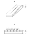
- FIG. 4A shows a perspective view of the magnetic scale
- FIG. 4B shows a cross-sectional view along the longitudinal direction of the magnetic scale
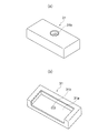
- FIG. 6A shows a top perspective view of the end cap
- FIG. 6B shows a bottom perspective view of the end cap
- FIG. 1 shows a perspective view of the motion guide device of the first embodiment of the present invention
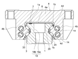
- FIG. 2 shows a cross-sectional view of the motion guide device orthogonal to the longitudinal direction of the track rail 1.
- the motion guide device includes a track rail 1 as a track member that extends linearly in the longitudinal direction, and a moving block as a moving member that is assembled to the track rail 1 through a large number of rollers 3 as rolling elements. 2 is provided.
- a groove 1a extending in the longitudinal direction is formed on the upper surface of the track rail 1, and a magnetic scale 7 is fitted in the groove 1a. After fitting the magnetic scale 7 in the groove 1a, the upper surface of the track rail 1 is covered with a plate cover 8 as a covering member.
- FIG. 1 shows a state in which the plate cover 8 is cut halfway to show the through-hole 18 and one through-hole 18 is exposed, but the plate cover 8 actually extends to the end of the track rail 1. All the through holes 18 are covered.
- Bolts as fastening members for fixing the track rail 1 to the base are inserted into the through holes 18.
- the through hole 18 has a counterbore 18 a having a diameter larger than the head of the bolt and a hole 18 b slightly larger than the screw portion of the bolt formed concentrically. .
- the height of the counterbore 18a is higher than the height of the head of the bolt so that the bolt is completely buried in the through hole 18.
- a roller rolling surface 1 b is formed on the track rail 1 as a rolling element rolling part on which the rolling element rolls.
- the track rail 1 has a substantially square cross section, and V-shaped recesses 20 are formed on the left and right side surfaces thereof.
- the roller rolling surface 1 b is formed on the upper and lower wall surfaces inclined by the recess 20.
- a total of four roller rolling surfaces 1 b are formed on the upper and lower sides.
- Each roller rolling surface 1 b extends elongated along the longitudinal direction of the track rail 1.
- the track rail 1 is made of metal such as steel.
- a groove 1 a extending in the longitudinal direction of the track rail 1 is formed on the upper surface of the track rail 1.
- the groove 1 a is formed between the plurality of through holes 18 on the upper surface of the track rail 1 and the end 21 in the width direction of the upper surface of the track rail 1.
- the groove 1a is separated from the plurality of through holes 18 in the width direction.
- the groove 1a includes a bottom surface 1a1 parallel to the top surface of the track rail 1 and a pair of side surfaces 1a2 perpendicular to the bottom surface 1a1.
- the magnetic scale 7 is fitted in the groove 1a.
- a double-sided tape 9 is bonded to the lower surface of the magnetic scale 7.
- the double-sided tape 9 has adhesive surfaces formed on both sides of a belt-like tape.
- the lower surface of the double-sided tape 9 is bonded to the bottom surface 1 a 1 of the groove 1 a of the track rail 1.
- the height of the side surface 1a2 of the groove 1a is higher than the height of the magnetic scale 7, and there is a step between the upper surface of the magnetic scale 7 and the upper surface of the track rail 1, that is, between the upper surface of the magnetic scale 7 and the lower surface of the plate cover 8. There is a gap in it.
- the plate cover 8 is made of a nonmagnetic metal such as stainless steel.
- the length of the plate cover 8 is equal to the length of the track rail 1.
- the thickness of the plate cover 8 is set to 0.2 to 0.4 mm, for example.
- a curved portion 22 that bulges outward and curves while drawing an arc is formed.
- an undercut portion 23 that is recessed from the lower end of the curved portion 22 toward the center in the width direction is formed.
- the undercut portion 23 and the curved portion 22 have the same shape over the entire length of the track rail 1.
- the plate cover 8 is provided at both ends in the width direction of the central portion 8a and the central portion 8a that covers the entire upper surface of the track rail 1 in the width direction perpendicular to the longitudinal direction, and is bent with respect to the central portion 8a.
- the engaging portion 8b is provided.
- the plate cover 8 is placed on the upper surface of the track rail 1 with a width wider than the width of the groove 1a.
- the central portion 8 a of the plate cover 8 is flat and contacts the upper surface of the track rail 1.
- the plate cover 8 simultaneously covers the magnetic scale 7 and the plurality of through holes 18 (see FIG. 2) on the upper surface of the track rail 1.
- the engaging portion 8b of the plate cover 8 is brought into contact with the curved portion 22 of the track rail 1 and the plate cover 8 is pushed straight down, the left and right engaging portions 8b are elastically deformed outward to overcome the curved portion 22, Thereafter, the engaging portion 8 b is fitted into the undercut portion 23.
- the plate cover 8 is fixed to the track rail 1 by the elastic force of the engaging portion 8b. If the engaging part 8b of the plate cover 8 functions as a snap fit, the shape is not limited to the shape shown in FIG.
- FIG. 4 shows a detailed view of the magnetic scale 7.
- FIG. 4A shows a perspective view of the magnetic scale 7, and
- FIG. 4B shows a cross-sectional view along the longitudinal direction of the magnetic scale 7.
- the magnetic scale 7 is also called a magnetic linear encoder, and N and S poles are alternately formed in the longitudinal direction on the surface of the magnetic scale 7.
- the magnetic scale 7 has a three-layer structure.
- the substrate 7a made of a nonmagnetic stainless steel plate having a thickness of 0.3 mm, for example, on the bottom surface side, and the first sheet 7b having a thickness of 0.5 mm, for example, on the substrate 7a.
- a second sheet 7c having a thickness of 0.5 mm, for example, on the first sheet 7b.
- the width of the magnetic scale 7 is 4 mm, for example.
- the substrate 7a is provided to improve the strength of the magnetic scale 7.
- a double-sided tape 9 for fixing the magnetic scale 7 to the track rail 1 is bonded to the lower surface of the substrate 7a.
- the first sheet 7b is formed in the shape of an elongated rectangular plate by kneading ferrite magnetic powder in a binder resin such as vulcanized rubber or elastomer.
- a binder resin such as vulcanized rubber or elastomer.
- the ferrite-based magnetic powder manganese zinc ferrite, nickel zinc ferrite, copper zinc ferrite and the like are used.
- the second sheet 7c is formed in the shape of an elongated rectangular plate by kneading rare earth magnetic powder into a binder resin such as vulcanized rubber or elastomer.
- the material of the binder resin of the first sheet 7b and the second sheet 7c is the same.
- the rare earth magnetic powder a powder of neodymium, samarium-cobalt or samarium-iron nitride is used.
- the first sheet 7b generates a higher magnetic flux density than the second sheet 7c.
- the magnetic scale 7 is manufactured through the following steps. First, the first sheet 7b and the second sheet 7c are formed separately. Next, the first sheet 7b and the second sheet 7c are overlapped and then heated to weld the first sheet 7b and the second sheet 7c. Next, N and S poles are alternately magnetized on the surface of the second sheet 7c. The arrangement pitch of the N pole and the S pole can be arbitrarily set, for example, 2 mm. Finally, the substrate 7a is bonded to the lower surface of the second sheet 7c. A decorative plate made of a nonmagnetic stainless steel plate having a thickness of about 0.1 mm can be bonded to the surface of the second sheet 7c.
- the magnetic scale 7 Since the second sheet 7c of the magnetic scale 7 includes a rare earth magnet, the magnetic scale 7 emits a high strength magnetic flux density.
- the first sheet 7b functions as a back yoke of the second sheet 7c and functions as a yoke that concentrates the magnetic lines of force generated from the second sheet 7c.
- This magnetic scale 7 generates a strong and stable magnetic flux density from its surface as compared with a magnetic scale using a ferrite magnet. Therefore, even if the magnetic scale 7 is covered with the plate cover 8, the magnetic flux density of the magnetic scale 7 can be measured by the magnetic sensor.
- FIG. I is a perspective view of the upper surface side of the end cap 31
- FIG. 6B is a perspective view of the lower surface side of the end cap 31.
- the end cap 31 is formed in a rectangular parallelepiped shape having a width wider than the width of the track rail 1. As shown in FIG.
- a recess 31 a having a shape matched to the track rail 1 is formed on the lower surface side of the end cap 31.
- the end cap 31 has an upper surface of the plate cover 8 at the end in the longitudinal direction of the track rail 1, a groove 1 a in the end surface 1 c in the longitudinal direction of the track rail 1 following the upper surface of the track rail 1, and a track. A portion of the left and right side surfaces 1 d of the track rail 1 that continues from the upper surface of the rail 1 is covered.
- the end cap 31 is fixed to the track rail 1 with screws.
- the plate cover 8 is sandwiched between the end cap 31 and the track rail 1.
- the end cap 31 is formed with a through hole 31b through which a screw passes.
- a through hole 19 (see FIG.
- the end cover member only needs to cover at least the groove 1a in the end surface 1c in the longitudinal direction of the track rail 1, the length of the plate cover 8 is longer than the length of the track rail 1, and the end of the plate cover 8 is
- the end cover member can also be formed by bending.
- the moving block 2 includes a moving block main body 4 as a moving body main body, and end plates 5 as lid members attached to both ends of the moving block main body 4 in the moving direction.
- the moving block main body 4 includes a central portion 4a facing the upper surface of the track rail 1 and side wall portions 4b extending downward from the left and right sides of the central portion 4a and facing the left and right side surfaces of the track rail 1.
- a structure such as a table that moves linearly is attached to the upper surface of the moving block 2 using attachment bolts.
- the moving block main body 4 is formed with a load roller rolling surface 4 d as a load rolling element rolling portion facing the rolling element rolling portion of the track rail 1.
- Two load roller rolling surfaces 4d facing the roller rolling surface 1b of the track rail 1 are formed on the side wall 4b of the moving block body 4.
- a roller circulation path as a rolling element circulation path including the loaded roller rolling surface 4d is formed.
- the roller circulation path includes a loaded roller rolling surface 4d facing the roller rolling surface 1b of the track rail 1, a no-load return path 14 parallel to the loaded roller rolling surface 4d, a loaded roller rolling surface 4d, and a no-load return path.
- the direction change path which connects 14 is provided.
- a plurality of rollers 3 are arranged in the roller circulation path of the moving block 2.
- the plurality of rollers 3 are held in series by the retainer 33 so as to be freely rotatable.
- the roller 3 is interposed between the roller rolling surface 1 b of the track rail 1 and the loaded roller rolling surface 4 d of the moving block body 4.
- the roller 3 rolls while receiving the loaded roller rolling path 24 (see FIG. 2, between the roller rolling surface 1b and the loaded roller rolling surface 4d).
- the roller 3 that has rolled to one end of the loaded roller rolling surface 4d of the moving block body 4 enters the no-load return path 14 after passing through the direction changing path.
- the head unit 34 includes a magnetic sensor 36 such as a magnetic flux magnetoresistive element or a Hall element that detects the intensity of the magnetic flux density of the magnetic scale 7, and a printed board 37 on which the magnetic sensor 36 is mounted.
- the magnetic flux density detected by the magnetic sensor 36 is signal-processed by an interpolator and transmitted to a driver or the like that controls the motor.
- the head unit 34 is formed by resin-sealing a magnetic sensor 36 mounted on a printed circuit board 37.
- the head unit 34 is fixed to the holder 35 with screws.
- the magnetic sensor 36 is positioned above the magnetic scale 7.
- the head unit 34 has a sufficient waterproof structure with coolant resistance. Since the head unit 34 is small and has a simple shape, a waterproof structure can be easily adopted, and the holder 35 to which the head unit 34 is attached need not have a waterproof structure.
- the outer seal in the moving direction of the holder 35 is attached with an end seal (not shown), a laminated contact scraper, a metal scraper, and the like.
- the end seal and the laminated contact scraper have a function of preventing foreign matters such as iron powder adhering to the surface of the plate cover 8 from entering the holder 35.
- the end seal and the laminated contact scraper come into contact with the plate cover 8 with a margin to remove foreign matters such as iron powder attached to the surface of the plate cover 8.
- the contact area between the stacked contact scraper and the plate cover 8 is larger than the contact area between the end seal and the plate cover 8.
- the metal scraper eliminates foreign matters such as spatter stuck to the plate cover 8.
- the metal scraper does not contact the plate cover 8, and there is a gap between the metal scraper and the plate cover 8.
- end seal and the laminated contact scraper can be interposed between the moving block and the holder, or either the end seal or the laminated contact scraper can be omitted.
- the motion guide device of this embodiment has been described above. According to the motion guide device of the present embodiment, the following effects can be obtained. Since the plate cover 8 that covers the magnetic scale 7 and the plate cover 18 that covers the through-hole 18 of the track rail 1 are combined, the iron powder adhering to the surface of the plate cover 8 is scraped with an end seal, a laminated contact scraper, or a metal scraper. Can be taken. Since the end seal, the laminated contact scraper, and the metal scraper do not directly contact the magnetic scale 7, it is possible to prevent the magnetic scale 7 from being adversely affected such as wear and deformation.
- the magnetic flux density of the magnetic scale 7 penetrates the plate cover 8 even if the magnetic scale 7 is covered with the plate cover 8. For this reason, the magnetic flux density of the magnetic scale 7 can be measured with high accuracy. Furthermore, if the magnetic scale 7 has a high magnetic flux density, the accuracy of the mounting position of the magnetic sensor 36 may be rough, so that the mounting of the magnetic sensor 36 becomes easy.
- the groove 1 a into which the magnetic scale 7 is fitted is formed between the plurality of through holes 18 on the upper surface of the track rail 1 and the end portions 21 in the width direction of the upper surface of the track rail 1, the through holes 18 of the track rail 1.
- the bolts can be tightened and removed easily. On the other hand, if the magnetic scale 7 is applied to the through hole 18, the bolt cannot be accessed unless the magnetic scale 7 is removed.
- a plate cover 8 is provided at both ends in the width direction of the central portion 8a and a central portion 8a that covers the entire upper surface of the track rail 1 in the width direction perpendicular to the longitudinal direction, and is bent with respect to the central portion 8a. Since the engagement portion 8b is provided, it is possible to prevent the coolant from entering from the end portion of the plate cover 8 in the width direction.
- An end cap 31 is provided at the end of the track rail 1 in the longitudinal direction, and the end cap 31 covers the groove 1a in the end surface of the track rail 1 in the longitudinal direction. It is possible to prevent the coolant from entering from the groove 1a in the portion. Since the coolant can be prevented from flowing to the ground surface of the magnetic scale 7 and the groove 1 a of the track rail 1, a double-sided tape or the like can be used as a method of attaching the magnetic scale 7 to the track rail 1. Becomes easier.
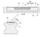
- FIG. 7 to 9 show the track rail 41 of the motion guide device according to the second embodiment of the present invention.
- a ball is used as a rolling element instead of a roller, and a ball rolling groove 41b in which the ball rolls as a rolling element rolling portion is formed on the upper left and right side surfaces of the track rail. It is formed.
- a ball circulation path including a loaded ball rolling groove facing the ball rolling groove 41 b of the track rail 41 is formed in the moving block (not shown).
- a groove 41a extending in the longitudinal direction of the track rail 41 is formed on the upper surface of the track rail 41, and the magnetic scale 7 is accommodated in the groove 41a.
- the covering member 44 covers the magnetic scale 7 and the through hole 18 of the track rail 41.
- the groove 41 a of this embodiment extends over the plurality of through holes 18 of the track rail 1.
- the width of the groove 41 a is wider than the counterbore part at the top of the through hole 18.
- the groove 41a includes a bottom surface 41a1 parallel to the top surface of the track rail 41 and a pair of side surfaces 41a2 perpendicular to the bottom surface 41a1.
- the magnetic scale 7 is accommodated in the groove 41a. Since the configuration of the magnetic scale 7 is the same as that of the magnetic scale of the first embodiment, the same reference numerals are given and description thereof is omitted. Note that the width of the magnetic scale 7 of the second embodiment can be made wider than the width of the magnetic scale of the first embodiment. For this reason, a ferrite-based magnetic powder can be used in place of the rare earth magnetic powder as the magnetic powder in which the N pole and the S pole are magnetized.
- the covering member 44 of this embodiment includes a main body portion 42 that is fitted in the groove 41 a of the track rail 41 and covers the plurality of through holes 18, and is placed on the main body portion 42 to cover the magnetic scale 7.
- the main body 42 is fitted into the groove 41 a of the track rail 41.
- the main body 42 has a flat cross-sectional shape and extends in the length direction of the track rail 41.
- the length of the main body 42 is equal to the length of the track rail 41.
- the width of the main body 42 is larger than the diameter of the counterbore of the through hole 18, and the main body 42 covers the through hole 18.
- the main body 42 is made of a nonmagnetic metal, such as stainless steel, or a nonmagnetic aluminum extrusion material. As shown in the enlarged view of FIG. 9, the main body 42 is bonded to the groove 41 a of the track rail 41 with a double-sided tape 43.
- a scale fitting groove 42 a extending in the longitudinal direction of the main body 42 is formed in the main body 42.
- the scale fitting groove 42a includes a bottom surface 42a1 parallel to the upper surface of the main body 42 and a pair of side surfaces 42a2 perpendicular to the bottom surface 42a1.
- the magnetic scale 7 is fitted into the scale fitting groove 42a.
- the magnetic scale 7 is fixed to the scale fitting groove 42 a with a double-sided tape 48.
- the height of the side surface 42a2 of the scale fitting groove 42a is higher than the height of the magnetic scale 7, and there is a step between the upper surface of the magnetic scale 7 and the upper surface of the main body 42, that is, the upper surface of the magnetic scale 7 and the lid 45. There is a gap between
- the upper surfaces of the magnetic scale 7 and the main body 42 are covered with a lid 45.
- the lid body 45 is made of a nonmagnetic metal such as stainless steel.
- the width of the lid 45 is the same as that of the main body 42 and is wider than the width of the scale fitting groove 42 a of the main body 42.
- the thickness of the lid 45 is set to 0.2 to 0.4 mm, for example.
- the lid 45 is fixed to the main body 42 with a double-sided tape 46.
- the motion guide device of the second embodiment the following effects are obtained. Since the covering member 44 that covers the magnetic scale 7 and the covering member 44 that covers the through-hole 18 of the track rail 41 are used together, foreign matters such as iron powder adhering to the surface of the covering member 44 are end sealed, laminated contact scraper, metal Can be scraped off with a scraper. Since the end seal, the laminated contact scraper, and the metal scraper do not directly contact the magnetic scale 7, it is possible to prevent the magnetic scale 7 from being adversely affected such as wear and deformation.
- the lid body 45 has a width wider than the width of the scale fitting groove 42a of the main body portion 42 and is placed on the surface of the main body portion 42, so that coolant is applied to the contact surface between the magnetic scale 7 and the scale fitting groove 42a. It can be prevented from flowing. Since the double-sided tape 48 can be used as a method for attaching the magnetic scale 7 to the main body 42, the magnetic scale 7 can be easily attached.
- the upper surface of the track rail in this embodiment means a surface located on the opposite side of the mounting surface of the track rail with respect to the base of the track rail, and it is necessary to always face upward when using the motion guide device. There is no. It is only necessary that the moving block is movable relative to the track rail, and the track rail may move during use.
- the track rail may be curved in an arc shape.
- the magnetic scale and the groove into which the magnetic scale is fitted may be curved in an arc shape in accordance with the track rail.
- the magnetic scale may be an incremental type or an absolute type.
- An origin return magnet may be provided in addition to the magnetic scale, and the origin may be detected by detecting the magnetic flux density of the origin return magnet with a magnetic sensor.
- the magnetic scale is bonded to the track rail using a double-sided tape, but it can be bonded to the track rail using an adhesive, or can be fixed to the track rail using a screw.
- the magnetic scale is bonded to the groove of the track rail, but the magnetic scale can also be bonded to the plate cover.
- the shape of the track rail and the moving block is an example, and various shapes can be selected according to the use of the motion guide device.
- the number of rolling elements rolling portions of the track rail can be two, or the rolling element rolling portions can be arranged on the upper surface of the track rail.
Landscapes
- Engineering & Computer Science (AREA)
- General Engineering & Computer Science (AREA)
- Mechanical Engineering (AREA)
- Transmission And Conversion Of Sensor Element Output (AREA)
- Bearings For Parts Moving Linearly (AREA)
Abstract
Description
Claims (6)
- 長手方向に伸びる転動体転走部を有すると共に、上面に締結部材が挿入される通し孔が開口する軌道部材と、
前記軌道部材に複数の転動体を介して移動可能に組み付けられる移動部材と、
前記軌道部材に形成され、長手方向に伸びる溝と、
前記溝に収容され、長手方向に交互にN極及びS極が形成される磁気スケールと、
前記磁気スケールを覆うと共に、前記軌道部材の前記通し孔を覆う覆い部材と、を備える磁気スケール付き運動案内装置。 - 前記磁気スケールは、前記N極及び前記S極が着磁された希土類磁石を含むことを特徴とする請求項1に記載の磁気スケール付き運動案内装置。
- 前記溝は、前記軌道部材の上面の前記複数の通し孔と、前記軌道部材の上面の幅方向の端部との間に形成されることを特徴とする請求項1又は2に記載の磁気スケール付き運動案内装置。
- 前記覆い部材は、前記軌道部材の上面を長手方向に対して直角な幅方向の全体に亘って覆う中央部と、前記中央部の幅方向の両端に設けられ、前記中央部に対して曲げられる係合部を有することを特徴とする請求項1又は2に記載の磁気スケール付き運動案内装置。
- 前記覆い部材は、
前記軌道部材の前記溝に嵌められ、前記軌道部材の前記複数の通し孔を覆うと共に、前記磁気スケールが嵌められるスケール嵌合溝が形成される本体部と、
前記スケール嵌合溝に嵌められた前記磁気スケールを覆う蓋体と、を備えることを特徴とする請求項1又は2に記載の磁気スケール付き運動案内装置。 - 前記磁気スケール付き運動案内装置はさらに、
前記軌道部材の上面に続く前記軌道部材の長手方向の端面における前記溝又は前記スケール嵌合溝を覆う端部覆い部材を備えることを特徴とする請求項1又は2に記載の磁気スケール付き運動案内装置。
Priority Applications (3)
| Application Number | Priority Date | Filing Date | Title |
|---|---|---|---|
| CN201480049259.3A CN105518324B (zh) | 2013-09-09 | 2014-09-03 | 带磁尺的运动引导装置 |
| DE112014004117.3T DE112014004117B4 (de) | 2013-09-09 | 2014-09-03 | Mit magnetischer Skala ausgestattete Bewegungsführungsvorrichtung |
| US14/915,745 US9581204B2 (en) | 2013-09-09 | 2014-09-03 | Magnetic-scale-equipped motion guide apparatus |
Applications Claiming Priority (2)
| Application Number | Priority Date | Filing Date | Title |
|---|---|---|---|
| JP2013-186015 | 2013-09-09 | ||
| JP2013186015A JP5797712B2 (ja) | 2013-09-09 | 2013-09-09 | 磁気スケール付き運動案内装置 |
Publications (1)
| Publication Number | Publication Date |
|---|---|
| WO2015033969A1 true WO2015033969A1 (ja) | 2015-03-12 |
Family
ID=52628438
Family Applications (1)
| Application Number | Title | Priority Date | Filing Date |
|---|---|---|---|
| PCT/JP2014/073225 Ceased WO2015033969A1 (ja) | 2013-09-09 | 2014-09-03 | 磁気スケール付き運動案内装置 |
Country Status (6)
| Country | Link |
|---|---|
| US (1) | US9581204B2 (ja) |
| JP (1) | JP5797712B2 (ja) |
| CN (1) | CN105518324B (ja) |
| DE (1) | DE112014004117B4 (ja) |
| TW (1) | TWI561744B (ja) |
| WO (1) | WO2015033969A1 (ja) |
Cited By (3)
| Publication number | Priority date | Publication date | Assignee | Title |
|---|---|---|---|---|
| CN108291578A (zh) * | 2016-01-18 | 2018-07-17 | Thk株式会社 | 滚动引导装置 |
| US11174897B2 (en) * | 2018-10-16 | 2021-11-16 | Thk Co., Ltd. | Sensor attachment member and sensor attachment method for rolling guide device |
| US11319996B2 (en) * | 2018-12-26 | 2022-05-03 | Thk Co., Ltd. | Sensor attachment structure for roller guiding device |
Families Citing this family (10)
| Publication number | Priority date | Publication date | Assignee | Title |
|---|---|---|---|---|
| JP6085658B1 (ja) * | 2015-10-28 | 2017-02-22 | Thk株式会社 | 位置検出装置及び位置検出装置付き運動案内装置 |
| JP6356750B2 (ja) * | 2016-09-02 | 2018-07-11 | Thk株式会社 | 異物検出装置、及びリニアガイド |
| JP1575127S (ja) * | 2016-11-16 | 2017-05-01 | ||
| DE102017201230A1 (de) * | 2017-01-26 | 2018-07-26 | Robert Bosch Gmbh | Linearbewegungsvorrichtung mit Lebensdauerüberwachung |
| JP2018157616A (ja) * | 2017-03-15 | 2018-10-04 | Thk株式会社 | 直動装置における発電システム |
| DE102017206584A1 (de) * | 2017-04-19 | 2018-10-25 | Robert Bosch Gmbh | Linearbewegungsvorrichtung mit Sensorhalter |
| CN108317169A (zh) * | 2018-04-04 | 2018-07-24 | 济南蓝海传动机械有限公司 | 一种线性滑轨防尘带 |
| JP7315414B2 (ja) * | 2019-08-28 | 2023-07-26 | 株式会社マキタ | 携帯用加工機の案内定規 |
| CN113021015A (zh) * | 2019-12-25 | 2021-06-25 | 苏州市阳山机械有限公司 | 镶钢导轨的安装定位结构及方法 |
| TWI740394B (zh) * | 2020-02-25 | 2021-09-21 | 直得科技股份有限公司 | 滑軌防塵蓋的固定構造 |
Citations (5)
| Publication number | Priority date | Publication date | Assignee | Title |
|---|---|---|---|---|
| JPH05280915A (ja) * | 1992-04-03 | 1993-10-29 | Sony Magnescale Inc | 磁気スケール |
| JPH07279958A (ja) * | 1994-04-06 | 1995-10-27 | Nippon Seiko Kk | リニアガイド及びボールねじの製造方法 |
| JP2001227542A (ja) * | 2000-02-18 | 2001-08-24 | Thk Co Ltd | 運動案内装置 |
| JP2005121215A (ja) * | 2003-10-11 | 2005-05-12 | Rexroth Star Gmbh | 測定装置を備えたガイド装置及びそのようなガイド装置の製造方法 |
| JP2012154431A (ja) * | 2011-01-26 | 2012-08-16 | Nsk Ltd | 直動案内装置の損傷防止部品 |
Family Cites Families (13)
| Publication number | Priority date | Publication date | Assignee | Title |
|---|---|---|---|---|
| JP2584875B2 (ja) * | 1989-11-08 | 1997-02-26 | テイエチケー 株式会社 | 直線摺動用ベアリング |
| US6253453B1 (en) * | 1993-06-30 | 2001-07-03 | Nsk Ltd | Methods of manufacturing a linear guide device and a ball screw device |
| JPH0953638A (ja) * | 1995-08-11 | 1997-02-25 | Nippon Thompson Co Ltd | 位置検出装置並びにこれを具備した軌道台ユニット及び案内ユニット |
| JPH1061664A (ja) * | 1996-08-15 | 1998-03-06 | Nippon Thompson Co Ltd | 直動転がり案内ユニット |
| TW435627U (en) * | 1999-03-05 | 2001-05-16 | Hiwin Tech Corp | A linear guideway with MR sensor |
| US6692153B2 (en) * | 2001-03-07 | 2004-02-17 | Ntn Corporation | Wheel support bearing assembly |
| DE10243021A1 (de) * | 2002-09-17 | 2004-03-25 | Ina-Schaeffler Kg | Führungsschiene eines Linearwälzlagers |
| JP4947535B2 (ja) * | 2005-02-01 | 2012-06-06 | 内山工業株式会社 | 磁気エンコーダ用ゴム組成物およびそれを用いた磁気エンコーダ |
| EP1731878A1 (de) * | 2005-06-07 | 2006-12-13 | AMO Automatisierung Messtechnik Optik GmbH | Maschinenführungselement mit kompensiertem Längenmesssystem |
| US7547141B2 (en) * | 2006-10-23 | 2009-06-16 | Hiwin Technologies Corp. | Linear motion guide apparatus having detecting device |
| JP4441525B2 (ja) * | 2006-12-07 | 2010-03-31 | 上銀科技股▲分▼有限公司 | 外掛け式感知器を備えたリニアスライドウェイ |
| CN101802424B (zh) * | 2007-09-14 | 2012-10-10 | Thk株式会社 | 导轨以及具备该导轨的运动引导装置 |
| US20100162582A1 (en) * | 2008-12-30 | 2010-07-01 | Chih-Mao Shiao | Positioning Device of a Magnetic Ruler |
-
2013
- 2013-09-09 JP JP2013186015A patent/JP5797712B2/ja active Active
-
2014
- 2014-09-03 CN CN201480049259.3A patent/CN105518324B/zh active Active
- 2014-09-03 DE DE112014004117.3T patent/DE112014004117B4/de active Active
- 2014-09-03 WO PCT/JP2014/073225 patent/WO2015033969A1/ja not_active Ceased
- 2014-09-03 US US14/915,745 patent/US9581204B2/en active Active
- 2014-09-09 TW TW103130965A patent/TWI561744B/zh active
Patent Citations (5)
| Publication number | Priority date | Publication date | Assignee | Title |
|---|---|---|---|---|
| JPH05280915A (ja) * | 1992-04-03 | 1993-10-29 | Sony Magnescale Inc | 磁気スケール |
| JPH07279958A (ja) * | 1994-04-06 | 1995-10-27 | Nippon Seiko Kk | リニアガイド及びボールねじの製造方法 |
| JP2001227542A (ja) * | 2000-02-18 | 2001-08-24 | Thk Co Ltd | 運動案内装置 |
| JP2005121215A (ja) * | 2003-10-11 | 2005-05-12 | Rexroth Star Gmbh | 測定装置を備えたガイド装置及びそのようなガイド装置の製造方法 |
| JP2012154431A (ja) * | 2011-01-26 | 2012-08-16 | Nsk Ltd | 直動案内装置の損傷防止部品 |
Cited By (3)
| Publication number | Priority date | Publication date | Assignee | Title |
|---|---|---|---|---|
| CN108291578A (zh) * | 2016-01-18 | 2018-07-17 | Thk株式会社 | 滚动引导装置 |
| US11174897B2 (en) * | 2018-10-16 | 2021-11-16 | Thk Co., Ltd. | Sensor attachment member and sensor attachment method for rolling guide device |
| US11319996B2 (en) * | 2018-12-26 | 2022-05-03 | Thk Co., Ltd. | Sensor attachment structure for roller guiding device |
Also Published As
| Publication number | Publication date |
|---|---|
| TWI561744B (en) | 2016-12-11 |
| CN105518324A (zh) | 2016-04-20 |
| TW201530007A (zh) | 2015-08-01 |
| US20160215825A1 (en) | 2016-07-28 |
| DE112014004117T5 (de) | 2016-06-09 |
| DE112014004117B4 (de) | 2021-04-01 |
| JP2015052362A (ja) | 2015-03-19 |
| CN105518324B (zh) | 2017-07-07 |
| JP5797712B2 (ja) | 2015-10-21 |
| US9581204B2 (en) | 2017-02-28 |
Similar Documents
| Publication | Publication Date | Title |
|---|---|---|
| JP5797712B2 (ja) | 磁気スケール付き運動案内装置 | |
| US9863478B2 (en) | Motion guide device | |
| JP3347766B2 (ja) | リニアエンコーダ及びこれを具備した案内ユニット | |
| US20060279140A1 (en) | Linear motor with integrated guidance | |
| JPH0953638A (ja) | 位置検出装置並びにこれを具備した軌道台ユニット及び案内ユニット | |
| WO2012073755A1 (ja) | 可撓性マグネット、可撓性マグネットの製造方法、磁気エンコーダ、アクチュエータ | |
| JP2007300759A (ja) | 可動マグネット型リニアモータを内蔵したスライド装置 | |
| US5416396A (en) | Linear encoder and a guide unit on which it is equipped | |
| JP5255395B2 (ja) | スケール付運動案内装置及びスケール付運動案内装置用軌道部材 | |
| JP4521221B2 (ja) | 可動マグネット型リニアモータを内蔵したスライド装置 | |
| JP5248150B2 (ja) | 可動コイル型リニアモータを内蔵したスライド装置 | |
| JP6356750B2 (ja) | 異物検出装置、及びリニアガイド | |
| EP1445584A1 (en) | Scale device | |
| JP5675009B2 (ja) | 位置検出装置 | |
| JP2003156364A (ja) | スライド位置検出装置を備えた直動装置 | |
| JP2006322811A (ja) | 磁気エンコーダ及び被検出部材 | |
| US7849551B2 (en) | Assembly type cleaning structure for an induction reader | |
| JP3488847B2 (ja) | リニアモータ | |
| JP5248149B2 (ja) | 可動コイル型リニアモータを内蔵したスライド装置 | |
| JP5530598B2 (ja) | モータおよびロボット | |
| JP2012107666A (ja) | 軌道レールカバー及び運動案内装置 | |
| JPH07274478A (ja) | リニア直流モータ及びこれを具備した駆動ユニット | |
| JP2006292459A (ja) | 磁気スケール |
Legal Events
| Date | Code | Title | Description |
|---|---|---|---|
| 121 | Ep: the epo has been informed by wipo that ep was designated in this application |
Ref document number: 14841793 Country of ref document: EP Kind code of ref document: A1 |
|
| WWE | Wipo information: entry into national phase |
Ref document number: 14915745 Country of ref document: US |
|
| WWE | Wipo information: entry into national phase |
Ref document number: 112014004117 Country of ref document: DE Ref document number: 1120140041173 Country of ref document: DE |
|
| 122 | Ep: pct application non-entry in european phase |
Ref document number: 14841793 Country of ref document: EP Kind code of ref document: A1 |