WO2015033918A1 - 光走査装置及び画像形成装置 - Google Patents
光走査装置及び画像形成装置 Download PDFInfo
- Publication number
- WO2015033918A1 WO2015033918A1 PCT/JP2014/073032 JP2014073032W WO2015033918A1 WO 2015033918 A1 WO2015033918 A1 WO 2015033918A1 JP 2014073032 W JP2014073032 W JP 2014073032W WO 2015033918 A1 WO2015033918 A1 WO 2015033918A1
- Authority
- WO
- WIPO (PCT)
- Prior art keywords
- cover member
- optical scanning
- scanning device
- light beam
- injection port
- Prior art date
- Legal status (The legal status is an assumption and is not a legal conclusion. Google has not performed a legal analysis and makes no representation as to the accuracy of the status listed.)
- Ceased
Links
Images



Classifications
-
- H—ELECTRICITY
- H04—ELECTRIC COMMUNICATION TECHNIQUE
- H04N—PICTORIAL COMMUNICATION, e.g. TELEVISION
- H04N1/00—Scanning, transmission or reproduction of documents or the like, e.g. facsimile transmission; Details thereof
- H04N1/00909—Cleaning arrangements or preventing or counter-acting contamination from dust or the like
-
- G—PHYSICS
- G02—OPTICS
- G02B—OPTICAL ELEMENTS, SYSTEMS OR APPARATUS
- G02B26/00—Optical devices or arrangements for the control of light using movable or deformable optical elements
- G02B26/08—Optical devices or arrangements for the control of light using movable or deformable optical elements for controlling the direction of light
- G02B26/10—Scanning systems
- G02B26/12—Scanning systems using multifaceted mirrors
-
- H—ELECTRICITY
- H04—ELECTRIC COMMUNICATION TECHNIQUE
- H04N—PICTORIAL COMMUNICATION, e.g. TELEVISION
- H04N1/00—Scanning, transmission or reproduction of documents or the like, e.g. facsimile transmission; Details thereof
- H04N1/00519—Constructional details not otherwise provided for, e.g. housings, covers
- H04N1/00551—Top covers or the like
-
- H—ELECTRICITY
- H04—ELECTRIC COMMUNICATION TECHNIQUE
- H04N—PICTORIAL COMMUNICATION, e.g. TELEVISION
- H04N1/00—Scanning, transmission or reproduction of documents or the like, e.g. facsimile transmission; Details thereof
- H04N1/00519—Constructional details not otherwise provided for, e.g. housings, covers
- H04N1/00557—Connection or assembly of components or elements
-
- H—ELECTRICITY
- H04—ELECTRIC COMMUNICATION TECHNIQUE
- H04N—PICTORIAL COMMUNICATION, e.g. TELEVISION
- H04N1/00—Scanning, transmission or reproduction of documents or the like, e.g. facsimile transmission; Details thereof
- H04N1/04—Scanning arrangements, i.e. arrangements for the displacement of active reading or reproducing elements relative to the original or reproducing medium, or vice versa
- H04N1/10—Scanning arrangements, i.e. arrangements for the displacement of active reading or reproducing elements relative to the original or reproducing medium, or vice versa using flat picture-bearing surfaces
-
- H—ELECTRICITY
- H04—ELECTRIC COMMUNICATION TECHNIQUE
- H04N—PICTORIAL COMMUNICATION, e.g. TELEVISION
- H04N1/00—Scanning, transmission or reproduction of documents or the like, e.g. facsimile transmission; Details thereof
- H04N1/04—Scanning arrangements, i.e. arrangements for the displacement of active reading or reproducing elements relative to the original or reproducing medium, or vice versa
- H04N1/113—Scanning arrangements, i.e. arrangements for the displacement of active reading or reproducing elements relative to the original or reproducing medium, or vice versa using oscillating or rotating mirrors
-
- H—ELECTRICITY
- H04—ELECTRIC COMMUNICATION TECHNIQUE
- H04N—PICTORIAL COMMUNICATION, e.g. TELEVISION
- H04N2201/00—Indexing scheme relating to scanning, transmission or reproduction of documents or the like, and to details thereof
- H04N2201/0077—Types of the still picture apparatus
- H04N2201/0094—Multifunctional device, i.e. a device capable of all of reading, reproducing, copying, facsimile transception, file transception
Definitions
- the present invention relates to a dust-proof measure for an optical scanning device used in an image forming apparatus such as a copying machine, a printer, a facsimile, or a complex machine thereof.
- an optical scanning device used in an electrophotographic image forming apparatus
- an optical scanning device having the following configuration is well known. That is, the light beam emitted from the light source is deflected by a rotating polygon mirror, and the deflected light beam is guided onto the photosensitive surface of the photosensitive member by an optical component such as a lens or a mirror, thereby forming a latent image on the photosensitive member.
- FIG. 6 shows an outline of components of an optical scanning apparatus that has been generally employed. A detailed description of the optical scanning device will be given in an embodiment described later.
- the optical scanning device when dirt such as dust adheres to the internal optical components, the amount of light beam on the surface of the photosensitive member decreases and density fluctuation occurs due to the adhering dust blocking the light beam.
- the amount of fine dust and chemical substances in the air corresponding to a size of 1 ⁇ m or less has increased, and deterioration of image quality due to contamination of optical components has become a problem as compared with the conventional case.
- a rotating polygon mirror installed inside the optical scanning device generates an air flow by rotating at high speed. And a wind flows in the fine space which connects the bonding location of a foaming member and the bubble connected continuously, and air flows from the inside to the outside in a certain location, and from the outside to the inside in a certain location.
- the air flowing from the outside to the inside contains fine dust that contaminates the optical components, so the more the device is operated, the more fine dust enters the inside and adheres to the surface of the optical components and inside the housing. Will go.
- dust contained in the airflow around the rotating polygon mirror adheres to the reflecting surface of the rotating polygon mirror rotated at high speed. That is, as the rotating polygon mirror rotates, Karman vortices and turbulence are generated in the vicinity of the reflecting surface of the rotating polygon mirror, and the airflow with dust strikes the reflecting surface violently.
- fine dust that collides with the reflecting surface of the rotating polygon mirror is accumulated, and the dirt progresses from a location where the amount of airflow hits, and the reflectance of the dirty location decreases.
- the reflectance decreases due to these stains the amount of light beam guided onto the photosensitive member decreases, causing a problem that the output image density becomes thin.
- Patent Document 1 proposes a configuration in which a part of a glass member is bonded and fixed to a housing.
- the dust-proof glass and the cover member are bonded and fixed by a thin member such as the double-sided tape, so that a gap is generated due to the warp of the cover member.
- the cover member has a large opening slit for emitting the light beam, it is difficult to increase the rigidity as in the case. For this reason, peeling of a double-sided tape etc. will occur by temporary deformation at the time of conveying a cover member, for example.
- the bonding method described in Patent Document 1 since the dustproof glass is fixed with a hard adhesive having a hardness of 60 or more, the temperature is caused by the difference in linear expansion between the housing in which the resin material is mainstream and the dustproof glass.
- the present invention has been made under such circumstances, and an object of the present invention is to prevent a molten elastic member from solidifying before forming an elastic portion, and to improve the dust-proof performance of the housing. .
- the present invention has the following configuration.
- a light source that emits a light beam, a rotating polygon mirror that deflects the light beam so that the light beam emitted from the light source scans a photosensitive member in a scanning direction, and the light beam deflected by the rotating polygon mirror
- a cover member formed with an emission port for emitting light from the inner space formed by the housing and the cover member toward the outside, a transparent member for passing the light beam and closing the emission port, A seal part formed by an elastic member for closing a gap between the transparent member and the cover member, and an injection for injecting the molten elastic member when forming the seal part
- a flow path formed in the cover member so as to surround the emission port along the edge of the emission port and through which the molten elastic member injected from the injection port flows.
- the cross-sectional area in the short direction of the emission port is larger than the cross-sectional area in the short direction of the flow path along the edge of the emission port far from the injection port in the longitudinal direction of the emission port, Optical scanning device.
- the melted elastic member can be prevented from solidifying before forming the elastic portion, and the dustproof performance can be improved.
- FIG. 1 Schematic of the image forming apparatus of the embodiment
- FIG. 1 A perspective view and a sectional view of an optical scanning device of an embodiment
- FIG. 6 shows an outline of components of an optical scanning apparatus that has been generally employed.
- An optical scanning apparatus that irradiates a photoconductor with a light beam to form an electrostatic latent image includes a rotary polygon mirror 42 that is a deflector, a motor unit 41 that rotates the rotary polygon mirror 42, and an optical member.
- the optical members are a collimator lens 43 and a cylindrical lens 44 that shape the incident light beam to the motor unit 41.
- the optical members are one or more f ⁇ lenses (hereinafter referred to as optical lenses) 60 for equalizing the scanning speed of the light beam on the photosensitive member and a reflection mirror 62 for guiding the light beam to the photosensitive member. .
- the rotating polygon mirror 42 having a large number of reflecting mirror surfaces on the outer periphery is rotated at high speed to deflect the incident light beam so that the light beam scans on the photoreceptor.
- the rotation axis direction of the rotary polygon mirror 42 of the motor unit 41 is the Z-axis direction
- the main scanning direction which is the scanning direction of the light beam, or the longitudinal direction of the reflection mirror 62 is the Y-axis direction, Y-axis and Z-axis.
- the direction perpendicular to the axis is taken as the X-axis direction.
- FIG. 1 is a schematic configuration diagram showing the overall configuration of a tandem type color laser beam printer of this embodiment.
- This laser beam printer (hereinafter simply referred to as a printer) has four image forming engines 10Y, 10M for forming toner images for yellow (Y), magenta (M), cyan (C) and black (Bk) colors. 10C, 10Bk (illustrated with a dashed line).
- the printer also includes an intermediate transfer belt 20 onto which toner images are transferred from the image forming engines 10Y, 10M, 10C, and 10Bk.
- the printer is configured to transfer the toner image that has been multiplex-transferred to the intermediate transfer belt 20 to a recording sheet P that is a recording medium to form a full-color image.
- a recording sheet P that is a recording medium to form a full-color image.
- the intermediate transfer belt 20 is formed in an endless shape and is wound around a pair of belt conveying rollers 21 and 22 so that the toner images formed by the respective image forming engines 10 are transferred while rotating in the direction of arrow B. It is configured. Further, a secondary transfer roller 65 is disposed at a position facing one belt conveying roller 21 with the intermediate transfer belt 20 interposed therebetween. The recording sheet P is inserted between the secondary transfer roller 65 and the intermediate transfer belt 20 that are in pressure contact with each other, and the toner image is transferred from the intermediate transfer belt 20.
- the four image forming engines 10Y, 10M, 10C, and 10Bk described above are arranged in parallel below the intermediate transfer belt 20, and toner images formed according to image information of each color are transferred to the intermediate transfer belt 20.
- These four image forming engines 10 are arranged along the rotation direction (arrow B direction) of the intermediate transfer belt 20, an image forming engine 10Y for yellow, an image forming engine 10M for magenta, and an image forming engine 10C for cyan. And an image forming engine 10Bk for black.
- an optical scanning device 40 that exposes a photosensitive drum 50, which is a photoconductor provided in each image forming engine 10, in accordance with image information is disposed.
- the optical scanning device 40 is shared by all the image forming engines 10Y, 10M, 10C, and 10Bk, and includes four semiconductor lasers (not shown) that emit laser beams modulated according to image information of each color.
- the optical scanning device 40 also includes a rotary polygon mirror 42 and a rotary polygon mirror that deflect each light beam so that the light beam corresponding to each photosensitive drum 50 scans along the axial direction (Y-axis direction) of the photosensitive drum 50.
- a motor unit 41 that rotates 42 is provided.
- Each light beam deflected by the rotary polygon mirror 42 is guided by an optical member installed in the optical scanning device 40 and guided onto the photosensitive drum 50 to expose each photosensitive drum 50.
- Each image forming engine 10 includes a photosensitive drum 50 and a charging roller 12 that charges the photosensitive drum 50 to a uniform background potential.
- Each image forming engine 10 includes a developing device 13 that develops an electrostatic latent image formed on the photosensitive drum 50 by being exposed to a light beam to form a toner image.
- the developing device 13 forms a toner image corresponding to the image information of each color on the photosensitive drum 50.
- a primary transfer roller 15 is disposed at a position facing the photosensitive drum 50 of each image forming engine 10 so as to sandwich the intermediate transfer belt 20.
- the primary transfer roller 15 transfers a toner image on the photosensitive drum 50 to the intermediate transfer belt 20 by applying a predetermined transfer voltage.
- the recording sheet P is supplied from the paper feed cassette 2 stored in the lower portion of the printer housing 1 to the inside of the printer, specifically, to the secondary transfer position where the intermediate transfer belt 20 and the secondary transfer roller 65 abut.
- the A pickup roller 24 and a paper feed roller 25 for pulling out the recording sheet P accommodated in the paper feed cassette 2 are arranged in parallel on the upper part of the paper feed cassette 2.
- a retard roller 26 that prevents double feeding of the recording sheet P is disposed at a position facing the paper feed roller 25.
- the conveyance path 27 of the recording sheet P inside the printer is provided substantially vertically along the right side surface of the printer housing 1.
- the recording sheet P drawn from the paper feed cassette 2 located at the bottom of the printer casing 1 moves up the transport path 27 and is sent to a registration roller 29 that controls the timing of the recording sheet P entering the secondary transfer position. It is done. Thereafter, after the toner image is transferred at the secondary transfer position, the recording sheet P is sent to a fixing device 3 (shown by a broken line) provided on the downstream side in the transport direction. Then, the recording sheet P on which the toner image is fixed by the fixing device 3 is discharged through a discharge roller 28 to a discharge tray 1a provided on the upper portion of the printer casing 1.
- the optical scanning device 40 In forming a full color image by the color laser beam printer configured as described above, first, the optical scanning device 40 exposes the photosensitive drum 50 of each image forming engine 10 at a predetermined timing according to image information of each color. As a result, a latent image corresponding to the image information is formed on the photosensitive drum 50 of each image forming engine 10.
- the latent image formed by the optical scanning device 40 is accurately reproduced at a predetermined position on the photosensitive drum 50, and a light beam for forming the latent image is formed. The amount of light must always be stable and produce a desired value.
- the image forming apparatus is not limited to the image forming apparatus described with reference to FIG.
- FIG. 2A is a perspective view showing the appearance of the optical scanning device 40 in which the opening of the housing 85 is covered with the cover member 104.
- FIG. 2B is a schematic cross-sectional view of the optical scanning device 40 in FIG. 2A, and shows the internal structure of the optical scanning device 40.
- the optical scanning device 40 includes a housing 85 and a cover member 104.
- the optical scanning device 40 includes a light source unit 55 (55a, 55b) that emits a light beam, a rotating polygon mirror 42 that reflects and deflects the light beam, and a motor unit 41 that rotates the rotating polygon mirror 42.
- the optical scanning device 40 includes an optical lens 60 (60a to 60d) for forming an image of the light beam on the photosensitive drum 50, and a reflection mirror 62 (62a to 62h) for guiding the light beam onto the photosensitive drum 50.
- the optical scanning device 40 includes a housing 85, a cover member 104, a dustproof glass 105 that is a transparent member, and a pressing member 106.
- the transparent member that covers the opening 104a of the cover member 104 is described as the dust-proof glass 105, but the present invention is not limited to this. That is, the member covering the light beam opening 104a may be a transparent member, and may be, for example, plastic.
- the housing 85 is for fixing and holding the optical component
- the cover member 104 is a cover for isolating the optical component disposed inside together with the housing 85 from the outside.
- the dust-proof glass 105 is a glass that is attached to the cover member 104 and transmits a light beam.
- the pressing member 106 is a member for fixing the dust-proof glass 105 to the cover member 104.
- the casing 85 has a bottom surface (bottom portion) that is a plane parallel to the XY plane, and an outer wall (also referred to as a side wall or an outer peripheral portion) that stands from the bottom surface and is substantially parallel to the Z-axis direction.
- the other end side of the outer peripheral portion is an opening (hereinafter also referred to as an opening portion) with respect to one end side of the outer peripheral portion connected to the bottom surface.
- the rotary polygon mirror 42 and other optical members are assembled into the optical scanning device by passing through the opening when the device is assembled.
- the housing 85 has a housing side engaging portion 87 with which a cover side engaging portion 88 provided on the cover member 104 described later is engaged.
- the cover side engaging portion 88 and the housing side engaging portion 87 constitute a snap fit mechanism, and the cover member 104 is fixed to the housing 85 by the snap fit mechanism.
- the light source unit 55 (55a, 55b) is provided with a plurality of light sources, for example, four colors in the case of a four-color image forming apparatus, and each is fixed to the outer peripheral portion of the housing 85.
- the light beam LY corresponding to the photosensitive drum 50Y emitted from the light source unit 55 is deflected by the rotary polygon mirror 42 and enters the optical lens 60a.
- the light beam LY that has passed through the optical lens 60a is incident on the optical lens 60b, passes through the optical lens 60b, and then is reflected by the reflection mirror 62a.
- the light beam LY reflected by the reflection mirror 62a passes through a transparent window (not shown) and scans the photosensitive drum 50Y.
- the light beam LM corresponding to the photosensitive drum 50M emitted from the light source unit 55 is deflected by the rotary polygon mirror 42 and enters the optical lens 60a.
- the light beam LM that has passed through the optical lens 60a enters the optical lens 60b, passes through the optical lens 60b, and is then reflected by the reflecting mirror 62b, the reflecting mirror 62c, and the reflecting mirror 62d.
- the light beam LM reflected by the reflecting mirror 62d passes through a transparent window (not shown) and scans the photosensitive drum 50M.
- the light beam LC corresponding to the photosensitive drum 50C emitted from the light source unit 55 is deflected by the rotary polygon mirror 42 and enters the optical lens 60c.
- the light beam LC that has passed through the optical lens 60c enters the optical lens 60d, and the light beam LC that has passed through the optical lens 60d is reflected by the reflection mirror 62e, the reflection mirror 62f, and the reflection mirror 62g.
- the light beam LC reflected by the reflecting mirror 62g passes through a transparent window (not shown) and scans the photosensitive drum 50C.
- the light beam LBk corresponding to the photosensitive drum 50Bk emitted from the light source unit 55 is deflected by the rotary polygon mirror 42 and enters the optical lens 60c.
- the light beam LBk that has passed through the optical lens 60c is incident on the optical lens 60d, passes through the optical lens 60d, and is reflected by the reflecting mirror 62h.
- the light beam LBk reflected by the reflecting mirror 62h passes through a transparent window (not shown) and scans the photosensitive drum 50Bk.
- the cover member 104 is attached to the housing 85 so as to cover the opening of the housing 85 in order to prevent the optical components provided in the housing 85 from being stained.
- the cover member 104 of the present embodiment includes an upper cover 110 (blocking surface) that is a first surface that covers the opening.
- the upper cover 110 has a cover side engaging portion 88 that engages with the housing side engaging portion 87.
- the cover member 104 has a rectangular opening 104a, which is four emission ports that emit the light beam LY, the light beam LM, the light beam LC, and the light beam LBk.
- the cover side engaging portion 88 is erected from the upper cover 110 of the cover member 104.
- the cover-side engaging portion 88 is moved along the outer surface of the outer peripheral portion of the housing 85, and the housing-side engaging portion 87 provided in the housing 85. Engage with.
- the cover member 104 is fixed to the housing 85 by the housing side engaging portion 87 and the cover side engaging portion 88 engaging with each other.
- the cover member 104 is placed on the housing 85, and the cover side engaging portion 88 of the cover member 104 and the housing side engaging portion 87 of the housing 85 are engaged to form an optical scanning device as shown in FIG. 40 is configured.
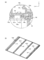
- FIGS. 3A is a perspective view of the cover member 104
- FIG. 3B is an enlarged view of the round frame portion of FIG. 3A.
- the cover member 104 is provided with a rectangular opening 104a having a width through which a light beam can pass.
- the cover member 104 is provided with a recess 104b for installing the dust-proof glass 105 on the opening 104a so as to be larger than the opening 104a (see FIG. 5A).
- the recess 104b is a continuous groove surrounding the opening 104a.
- a claw 104c for fixing the pressing member 106 that presses the dust-proof glass 105 toward the cover member 104 is provided around the recess 104b in the short direction (Y-axis direction) of the cover member 104 (the longitudinal direction of the opening 104a). Multiple).
- the pressing member 106 is provided with attachment portions 106a corresponding to the respective claw portions 104c.
- the fixing of the pressing member 106 to the cover member 104 is performed according to the following procedure. First, the claw portions 104 c are passed through the hole portions 106 b corresponding to the respective claw portions 104 c provided on the pressing member 106. Then, after the cover member 104 and the pressing member 106 are brought into close contact with each other, the pressing member 106 is slid in the short direction of the cover member 104. Thereby, the claw part 104c and the attaching part 106a are engaged, and the pressing member 106 can be fixed to the cover member 104.
- the pressing member 106 has a rectangular opening 106c having a width through which the light beam can pass, and the opening 106c is provided so as to be positioned in the light beam emitting direction from the opening 104a of the cover member 104. Yes.
- the pressing member 106 has a pressing portion (not shown) for pressing the dust-proof glass 105 against the cover member 104.
- the pressing portion is a surface on the back side of the pressing member 106 shown in FIG. 3B, that is, a surface on the side facing the cover member 104 of the pressing member 106.
- the pressing portion is provided at a position that does not block the light beam and is in contact with the dust-proof glass 105, and is longer than the width (length in the longitudinal direction) of the dust-proof glass 105 so that the pressing portion presses the dust-proof glass 105 uniformly. It is formed by a plane that is long in the direction (X-axis direction). This is because when the width of the pressing portion is narrower than the width of the dust-proof glass 105, the pressing portion locally presses the dust-proof glass 105, and the dust-proof glass 105 may be deformed.
- the collar cover member 104 is provided with an elastic portion 107 which is a seal portion formed integrally with the upper cover 110.
- the elastic portion 107 is provided to seal the gap between the opening 104a of the cover member 104 and the dust-proof glass 105 and prevent dust and the like from entering the inside of the housing 85, that is, to prevent dust.
- the elastic part 107 is molded in two colors together with the upper cover 110.
- the elastic part 107 is formed by a method such as insert molding or outsert molding in which after the upper cover 110 is molded, the upper cover 110 is placed in another mold and the elastic part 107 is additionally molded.
- the An elastic member, which is a molding material of the elastic portion 107 has a small heat capacity and is easy to cool and harden.
- the heel elastic part 107 is provided so that the width from the tip part 107a1 to the tip part 107b1 which is the protruding part of the elastic part 107 is smaller than the width of the dustproof glass 105 (see FIG. 4). Therefore, when the dust-proof glass 105 is placed on the elastic portion 107 and the pressing member 106 is attached to the cover member 104, the dust-proof glass 105 is pressed and fixed while being sandwiched between the pressing member 106 and the elastic portion 107. At this time, the elastic portion 107 continuously contacts the dustproof glass 105 along the lower surface of the dustproof glass 105, that is, the outer periphery of the surface of the dustproof glass 105 facing the cover member 104. For this reason, the gap between the cover member 104 and the dust-proof glass 105 can be completely filled, and the dust-proof performance is greatly improved.
- FIG. 4 is a cross-sectional view of the vicinity of the inlet 104d of the cover member 104 cut in the X-axis direction.
- the elastic portion 107 is formed so as to surround the opening 104a of the cover member 104, and forms a rectangular frame. That is, the recess 104b is formed in the cover member 104 so as to surround the edge of the opening 104a. Since the elastic portion 107 is molded into the concave portion 104b, the elastic portion 107 surrounds the edge of the opening portion 104a similarly to the concave portion 104b.
- the rectangular elastic portion 107 having four sides, a cross section of a side 107a (see FIG.
- a cross section 107 ⁇ A cross section of a side 107b (refer to FIG. 3B) facing the injection port 104d of the elastic portion 107 (referred to as a far side) is a cross section 107 ⁇ .
- the cross-sectional area of the cross section 107 ⁇ of the side 107a near the injection port 104d of the elastic portion 107 is 107aS
- the cross-sectional area 107aS has a constant cross-sectional area in the Y-axis direction.
- the cross-sectional area 107bS has a constant cross-sectional area in the Y-axis direction.
- the cross section 107 ⁇ and the cross section 107 ⁇ have a convex shape in which a part projects to the positive side in the Z-axis direction, and has a shape having tip portions 107a1 and 107b1. Since the cross-sections 107 ⁇ and 107 ⁇ have the tip portions 107a1 and 107b1, when the dust-proof glass 105 is pressed toward the cover member 104 by the holding member 106, the gap between the dust-proof glass 105 and the upper cover 110 is more tightly closed. Can do.
- the shape of the cross section 107 ⁇ and the cross section 107 ⁇ may be simply rectangular, the dustproof performance can be further improved by reducing the area where the elastic portion 107 is in contact with the dustproof glass 105. For this reason, in the present embodiment, the shapes of the cross sections 107 ⁇ and 107 ⁇ are convex.
- the heights of the cross section 107 ⁇ and the cross section 107 ⁇ from the flow path 104e are equal, the length (hereinafter referred to as width) of the cross section 107 ⁇ in the X-axis direction is 107al, and the width of the cross section 107 ⁇ is 107bl, the relationship between the width 107al and the width 107bl is 107a1> 107b1. Therefore, the relationship between the cross-sectional areas 107aS and 107bS of the two cross-sections 107 ⁇ and 107 ⁇ is 107aS> 107bS.
- the height of the cross section 107 ⁇ and the cross section 107 ⁇ from the flow path 104e means the height from the bottom surface of the flow path 104e to the tip portions 107a1 and 107b1 of the cross section 107 ⁇ and the cross section 107 ⁇ (h in FIG. 4).
- the height from the flow path 104e is equal to the height h of the cross sections 107 ⁇ and 107 ⁇ .
- the width of the cross section of the side 107c is made larger than the width 107b1 of the cross section 107 ⁇ of the side 107b. That is, the cross-sectional area of the side 107c is made larger than the cross-sectional area 107 ⁇ of the side 107b.
- the flow path of the elastic member formed by the mold for molding the elastic portion 107 and the cover member 104 is in the direction of the arrow shown in FIG. Therefore, the melted elastic member flows in the order of the cross section 107 ⁇ part ⁇ the cross section 107 ⁇ part. That is, the elastic member injected from the injection port 104d provided in the cover member 104 is divided into a flow in the negative direction of the Y-axis direction and a flow in the positive direction of the Y-axis direction. These two flows later flow in the positive and negative Y-axis directions through the flow path 104e of the side 107a that becomes the cross section 107 ⁇ of the elastic portion 107, respectively.
- the directions of the two flows are changed by 90 degrees, and both sides 107c flow in the negative direction of the X-axis direction. Then, the flow passes through the flow path 104e of the side 107b, which becomes the cross section 107 ⁇ of the elastic portion 107, in the direction opposite to the flow direction of the side 107a, and merges.
- the elastic member has low fluidity, and if the cross-sectional area of the cross-section 107 ⁇ is provided as the same cross-sectional area as the cross-section 107 ⁇ as in the prior art, the elastic member is solidified before the elastic portion 107 is formed. As a result, the space between the cover member 104 and the dustproof glass 105 cannot be completely filled, and the dustproof performance may not be obtained.
- the sectional area 107aS of the section 107 ⁇ is configured to be larger than the sectional area 107bS of the section 107 ⁇ (107aS> 107bS). Thereby, the fluidity of the elastic member in the vicinity of the injection port 104d is improved, and the molten elastic member is prevented from solidifying before forming the elastic portion 107.
- FIG. 5A is a cross-sectional view of the main part when the optical scanning device 40 is cut in the X-axis direction, and in particular, the longitudinal direction of the optical scanning device 40 in the four openings 104 a provided in the cover member 104. It shows about the opening part 104a of a direction (X-axis direction) edge part.
- the elastic member 108 is provided between the casing 85 and the cover member 104. As described above, the elastic member 108 fills the space between the casing 85 and the cover member 104 to obtain dustproof performance.
- FIG. 5B is a perspective view of the cover member 104.
- FIG. 5B shows the surface of the cover member on the inner side of the optical scanning device 40.
- the elastic portion 107 (the cross sections 107 ⁇ and 107 ⁇ ) is provided on the outer surface of the cover member 104.
- An injection port 104 d is connected to each of the recesses 104 b surrounding the four openings 104 a of the cover member 104.
- FIG. 5B shows the back side of the bottom of the inlet 104d, and the molten elastic member is poured from the entrance on the back side of FIG. 5B.
- the injection port 104d is formed between both ends of the opening 104a in the longitudinal direction of the opening 104a, and is connected to the recess 104d as a flow path from there.
- the material of the elastic portion 107 is injected into the injection port 104d from the outside of the cover member 104 (from the Z-axis direction + side to the ⁇ side in FIG. 5B).
- the material of the elastic member 108 is injected into the injection port 108a from the housing 85 side of the cover member 104 (from the Z-axis direction negative side to the positive side in FIG. 5B).
- the elastic portion 107 and the elastic member 108 are made of the same material.
- the elastic portion 107 and the elastic member 108 can be integrally formed with the cover member 104, and the elastic portion 107 and the elastic member 108 can be formed from both sides of the cover member 104 in a single process. Can be molded. For this reason, the process can be greatly eliminated as compared with the conventional method of attaching and fixing the elastic member to the cover member 104, and the dustproof performance can be stabilized. As described above, according to this embodiment, the melted elastic member can be prevented from solidifying before forming the elastic portion, and the dustproof performance of the housing can be improved.
Landscapes
- Engineering & Computer Science (AREA)
- Multimedia (AREA)
- Signal Processing (AREA)
- Physics & Mathematics (AREA)
- General Physics & Mathematics (AREA)
- Optics & Photonics (AREA)
- Facsimile Scanning Arrangements (AREA)
- Mechanical Optical Scanning Systems (AREA)
- Laser Beam Printer (AREA)
Abstract
溶融された弾性部材が弾性部を形成する前に固化することを防止し、筐体の防塵性能を向上させること。 開口部104aと、防塵ガラス105と、防塵ガラス105とカバー部材104との間隙を塞ぐための弾性部107と、弾性部107を形成する際に、溶融した弾性部材を注入する注入口104dと、注入口104dにより注入された溶融した弾性部材が、弾性部107を形成するために流し込まれる流路104eと、を備え、溶融した弾性部材が注入口104dから注入され、流路104eに流し込まれて弾性部107を形成したときに、注入口104dに近い側の開口部104aの短手方向における弾性部107の断面の面積が、注入口104dから遠い側の短手方向における弾性部107の断面の面積よりも大きい。
Description
本発明は、複写機、プリンタ、ファクシミリ、それらの複合機等の画像形成装置に用いられる光走査装置の防塵対策に関する。
電子写真方式の画像形成装置に用いられる光走査装置としては、次のような構成を備える光走査装置が周知である。即ち、光源から射出される光ビームを回転多面鏡により偏向させ、偏向された光ビームをレンズやミラーなどの光学部品により感光体の感光面上に導くことによって、感光体上に潜像画像を形成する光走査装置である。図6に従来一般的に採用されている光走査装置の構成部品の概要を示す。尚、光走査装置の詳細な説明は後述する実施の形態において行う。光走査装置では、内部の光学部品に塵埃等の汚れが付着した場合、付着した塵埃が光線を遮ることで感光体面上における光ビームの光量が低下し濃度変動が発生する。近年、大気汚染の結果、1μm以下のサイズに相当する大気中の微細粉塵や化学物質量が増加しており、従来に増して光学部品の汚れによる画質の低下が課題になってきている。
外部から光走査装置内部への塵埃等の侵入を防ぐために、光走査装置の外周部の隙間には、発泡部材を挟むことでシールする対策や、テープを貼る等の対策を施す方法が多く用いられているが、以下に説明する理由等によって、より密閉性を高める必要がある。近年の画像形成速度の高速化の要望に対して、従来の製品に比べて回転多面鏡の回転速度を速める必要性がある。光走査装置内部に設置された回転多面鏡は、高速回転をすることによって気流を発生させる。そして、発泡部材の張り合わせ箇所や連続的につながった気泡内を結ぶ微細な空間内を風が流れ、ある箇所では内部から外部へ、ある箇所では外部から内部へと空気が流れる。外部から内部へ流れる空気中には、光学部品を汚す微細粉塵が含まれているため、装置が稼動すればするほど内部へと微細粉塵が浸入し、光学部品表面や筐体内部に付着していくことになる。特に、回転多面鏡の周囲の気流に含まれる塵埃が高速回転した回転多面鏡の反射面に付着してしまう。即ち、回転多面鏡が回転することで回転多面鏡の反射面付近でカルマン渦、乱気流が発生し、塵埃をのせた気流が反射面に激しくぶつかる。結果として回転多面鏡の反射面に衝突する微細な粉塵が堆積され、気流がぶつかる量が多い箇所から汚れが進行し、汚れた箇所の反射率が低下していく。そして、これらの汚れによる反射率の低下に伴い感光体上に導かれる光ビームの光量が低下して、出力される画像濃度が薄くなるという課題が発生してしまう。
光走査装置では、光走査装置内で偏向された光ビームを感光体上に案内するために、光走査装置内部から外部へと光ビームを送り出すための開口部が必要になる。このため、光走査装置では、光ビームを光走査装置の外部へ射出するための開口部を必ず有している。この開口部では、上述のような汚れを回避するために、両面テープによりガラス部材を貼付する対策が主流となっている。また、例えば特許文献1では、ガラス部材の一部を筐体に接着固定する構成が提案されている。
しかし、両面テープを用いるような構成では、両面テープのような薄い部材によって防塵用ガラスとカバー部材を接着固定しているため、カバー部材のソリ等によって隙間が生じてしまう。また、カバー部材は、光ビームの射出用の大きな開口スリットを有していることから、筐体のように剛性を上げることが困難である。このため、例えばカバー部材を搬送する際の一時的な変形によって、両面テープの剥がれ等がおきてしまう。更に、特許文献1に記載の接着方式では、硬度60以上と硬い接着剤により防塵用ガラスを固定してしまうため、樹脂材が主流になっている筐体と防塵用ガラスの線膨張差により温度変動時の歪みが発生してしまう。また、筐体と防塵用ガラスが接触する箇所全域に接着剤を塗布していないことから、完全に隙間をなくすことが難しいだけでなく、光ビームを透過するガラス部材に接着剤を塗布する際の糸引き等でガラス部材の表面を汚してしまうおそれもある。
そこで、防塵用ガラスとカバー部材との間を、ゴム等の弾性部材で埋める方法があるが、まずゴムを貼り付け、そのあとに防塵ガラスを固定するため、工程が長くなってしまう。また、ホットメルト等のカバー部材との一体成形ができる弾性部材を用いる場合にも、溶融された弾性部材の流動性が低く、意図する形状を形作る前に、弾性部材が固化してしまうという課題もある。
本発明は、このような状況のもとでなされたもので、溶融された弾性部材が弾性部を形成する前に固化することを防止し、筐体の防塵性能を向上させることを目的とする。
前述した課題を解決するために、本発明は以下の構成を備える。
(1)光ビームを出射する光源と、前記光源から出射された光ビームが感光体上を走査方向に走査するように前記光ビームを偏向する回転多面鏡と、前記回転多面鏡により偏向された光ビームを前記感光体に導く光学部材と、前記回転多面鏡及び前記光学部材が設置される筐体と、前記筐体に取り付けられるカバー部材であって、前記回転多面鏡によって偏向された光ビームを前記筺体と前記カバー部材とで形成される内部空間から外部に向けて出射させるための出射口が形成されたカバー部材と、前記光ビームを通過させ、前記出射口を塞ぐための透明部材と、弾性部材により形成され、前記透明部材と前記カバー部材との間隙を塞ぐためのさせるためのシール部と、前記シール部を形成する際に、溶融した前記弾性部材を注入する注入口と、前記出射口の縁に沿って前記出射口を囲むように前記カバー部材に形成され、前記注入口から注入された溶融した前記弾性部材が流れる流路と、を備え、前記注入口は、前記出射口の長手方向において前記出射口の両端の間で前記流路に接続されており、前記出射口の長手方向において前記注入口に近い側の前記出射口の縁に沿う前記流路の前記出射口の短手方向における断面積が、前記出射口の長手方向において前記注入口から遠い側の前記出射口の縁に沿う前記流路の前記短手方向における断面積よりも大きいことを特徴とする光走査装置。
本発明によれば、溶融された弾性部材が弾性部を形成する前に固化することを防止し、防塵性能を向上させることができる。
以下、本発明を実施するための形態を、実施例により図面を参照しながら詳しく説明する。まず、従来の光走査装置の構成を説明し、その後に実施例を説明する。
[従来の光走査装置の構成]
図6に従来一般的に採用されている光走査装置の構成部品の概要を示す。感光体に光ビームを照射し静電潜像を形成する光走査装置は、偏向器である回転多面鏡42と回転多面鏡42を回転させるモータユニット41と、光学部材とを備える。光学部材は、モータユニット41への入射光束を整形するコリメータレンズ43やシリンドリカルレンズ44である。また、光学部材は、感光体上における光ビームの走査速度を等速度にさせるための1枚以上のfθレンズ(以下、光学レンズという)60及び感光体へと光ビームを導く反射ミラー62である。モータユニット41では、多数の反射鏡面を外周に有する回転多面鏡42を高速回転することで、光ビームが感光体上を走査するように入射する光ビームを偏向する。尚、以下の説明において、モータユニット41の回転多面鏡42の回転軸方向をZ軸方向、光ビームの走査方向である主走査方向又は反射ミラー62の長手方向をY軸方向、Y軸及びZ軸に垂直な方向をX軸方向とする。
図6に従来一般的に採用されている光走査装置の構成部品の概要を示す。感光体に光ビームを照射し静電潜像を形成する光走査装置は、偏向器である回転多面鏡42と回転多面鏡42を回転させるモータユニット41と、光学部材とを備える。光学部材は、モータユニット41への入射光束を整形するコリメータレンズ43やシリンドリカルレンズ44である。また、光学部材は、感光体上における光ビームの走査速度を等速度にさせるための1枚以上のfθレンズ(以下、光学レンズという)60及び感光体へと光ビームを導く反射ミラー62である。モータユニット41では、多数の反射鏡面を外周に有する回転多面鏡42を高速回転することで、光ビームが感光体上を走査するように入射する光ビームを偏向する。尚、以下の説明において、モータユニット41の回転多面鏡42の回転軸方向をZ軸方向、光ビームの走査方向である主走査方向又は反射ミラー62の長手方向をY軸方向、Y軸及びZ軸に垂直な方向をX軸方向とする。
[画像形成装置]
実施例の画像形成装置の構成を説明する。図1は本実施例のタンデム型のカラーレーザービームプリンタの全体構成を示す概略構成図である。このレーザービームプリンタ(以下、単にプリンタという)はイエロー(Y)、マゼンタ(M)、シアン(C)及びブラック(Bk)の色毎にトナー像を形成する4基の作像エンジン10Y、10M、10C、10Bk(一点鎖線で図示)を備える。また、プリンタは、各作像エンジン10Y、10M、10C、10Bkからトナー像が転写される中間転写ベルト20を備える。そして、プリンタは、中間転写ベルト20に多重転写されたトナー像を記録媒体である記録シートPに転写してフルカラー画像を形成するように構成されている。以降、各色を表す符号Y、M、C、Bkは、必要な場合を除き省略する。
実施例の画像形成装置の構成を説明する。図1は本実施例のタンデム型のカラーレーザービームプリンタの全体構成を示す概略構成図である。このレーザービームプリンタ(以下、単にプリンタという)はイエロー(Y)、マゼンタ(M)、シアン(C)及びブラック(Bk)の色毎にトナー像を形成する4基の作像エンジン10Y、10M、10C、10Bk(一点鎖線で図示)を備える。また、プリンタは、各作像エンジン10Y、10M、10C、10Bkからトナー像が転写される中間転写ベルト20を備える。そして、プリンタは、中間転写ベルト20に多重転写されたトナー像を記録媒体である記録シートPに転写してフルカラー画像を形成するように構成されている。以降、各色を表す符号Y、M、C、Bkは、必要な場合を除き省略する。
中間転写ベルト20は、無端状に形成され、一対のベルト搬送ローラ21、22にかけ回されており、矢印B方向に回転動作しながら各作像エンジン10で形成されたトナー像が転写されるように構成されている。また、中間転写ベルト20を挟んで一方のベルト搬送ローラ21と対向する位置には二次転写ローラ65が配設されている。記録シートPは、互いに圧接する二次転写ローラ65と中間転写ベルト20との間に挿通されて、中間転写ベルト20からトナー像が転写される。中間転写ベルト20の下側には前述した4基の作像エンジン10Y、10M、10C、10Bkが並列的に配設されており、各色の画像情報に応じて形成したトナー像を中間転写ベルト20に転写するようになっている(以下、一次転写という)。これら4基の作像エンジン10は、中間転写ベルト20の回動方向(矢印B方向)に沿って、イエロー用の作像エンジン10Y、マゼンタ用の作像エンジン10M、シアン用の作像エンジン10C及びブラック用の作像エンジン10Bkの順に配設されている。
また、作像エンジン10の下方には、各作像エンジン10に具備された感光体である感光ドラム50を画像情報に応じて露光する光走査装置40が配設されている。尚、図1では光走査装置40の詳細な図示及び説明は省略し、図2(b)を用いて後述する。光走査装置40は全ての作像エンジン10Y、10M、10C、10Bkに共用されており、各色の画像情報に応じて変調されたレーザービームを射出する図示しない4基の半導体レーザーを備えている。また、光走査装置40は、各感光ドラム50に対応する光ビームが感光ドラム50の軸方向(Y軸方向)に沿って走査するように各光ビームを偏向する回転多面鏡42及び回転多面鏡42を回転させるモータユニット41を備えている。回転多面鏡42によって偏向された各光ビームは、光走査装置40内に設置された光学部材に案内されて感光ドラム50上に導かれ、各感光ドラム50を露光する。
各作像エンジン10は、感光ドラム50と、感光ドラム50を一様な背景部電位にまで帯電させる帯電ローラ12と、を備える。また、各作像エンジン10は、光ビームによって露光されることで感光ドラム50上に形成された静電潜像を現像してトナー像を形成する現像器13を備えている。現像器13は、感光ドラム50上に各色の画像情報に応じたトナー像を形成する。
各作像エンジン10の感光ドラム50に対向する位置には、中間転写ベルト20を挟むようにして一次転写ローラ15が配設されている。一次転写ローラ15は、所定の転写電圧が印加されることにより、感光ドラム50上のトナー像が中間転写ベルト20に転写される。
一方、記録シートPはプリンタ筐体1の下部に収納される給紙カセット2からプリンタの内部、具体的には中間転写ベルト20と二次転写ローラ65とが当接する二次転写位置へ供給される。給紙カセット2の上部には、給紙カセット2内に収容された記録シートPを引き出すためのピックアップローラ24及び給紙ローラ25が並設されている。また、給紙ローラ25と対向する位置には、記録シートPの重送を防止するリタードローラ26が配設されている。プリンタの内部における記録シートPの搬送経路27は、プリンタ筐体1の右側面に沿って略垂直に設けられている。プリンタ筐体1の底部に位置する給紙カセット2から引き出された記録シートPは、搬送経路27を上昇し、二次転写位置に対する記録シートPの突入タイミングを制御するレジストレーションローラ29へと送られる。その後、記録シートPは、二次転写位置においてトナー像が転写された後、搬送方向の下流側に設けられた定着器3(破線で図示)へと送られる。そして、定着器3によってトナー像が定着された記録シートPは、排出ローラ28を経て、プリンタ筐体1の上部に設けられた排紙トレイ1aに排出される。
このように構成されたカラーレーザービームプリンタによるフルカラー画像の形成に当たっては、まず、各色の画像情報に応じて光走査装置40が各作像エンジン10の感光ドラム50を所定のタイミングで露光する。これによって各作像エンジン10の感光ドラム50上には画像情報に応じた潜像画像が形成される。ここで、良質な画質を得るためには、光走査装置40によって形成される潜像画像が感光ドラム50上の所定の位置に精度よく再現され、かつ、潜像画像を形成するための光ビームの光量は常に安定して所望の値を出せるものでなければならない。尚、画像形成装置は、図1で説明した画像形成装置に限定されない。
[光走査装置の説明]
図2~図5を用いて、本実施例の光走査装置について説明する。図2(a)は、筐体85の開口がカバー部材104で覆われた光走査装置40の外観を示す斜視図である。図2(b)は、図2(a)の光走査装置40の概略断面図であり、光走査装置40の内部構造を示す図である。光走査装置40は、筐体85とカバー部材104とを備える。また、光走査装置40は、光ビームを射出する光源ユニット55(55a、55b)、光ビームを反射、偏向する回転多面鏡42、回転多面鏡42を回転させるモータユニット41を備える。また、光走査装置40は、光ビームを感光ドラム50上に結像するための光学レンズ60(60a~60d)、光ビームを感光ドラム50上へ案内するための反射ミラー62(62a~62h)を備える。更に、光走査装置40は、筐体85、カバー部材104、透明部材である防塵ガラス105、押圧部材106を備える。尚、本実施例では、カバー部材104の開口部104aを覆う透明部材を防塵ガラス105として説明するが、これに限定されるものではない。即ち、光ビームの開口部104aを覆う部材は透明部材であればよく、例えばプラスチックであってもよい。筐体85は、光学部品を固定保持するためのものであり、カバー部材104は、筐体85と共に内部に配置された光学部品を外部から隔離するためのカバーである。また、防塵ガラス105は、カバー部材104に装着され、光ビームを透過させるためのガラスである。更に、押圧部材106は、防塵ガラス105をカバー部材104に固定するための部材である。
図2~図5を用いて、本実施例の光走査装置について説明する。図2(a)は、筐体85の開口がカバー部材104で覆われた光走査装置40の外観を示す斜視図である。図2(b)は、図2(a)の光走査装置40の概略断面図であり、光走査装置40の内部構造を示す図である。光走査装置40は、筐体85とカバー部材104とを備える。また、光走査装置40は、光ビームを射出する光源ユニット55(55a、55b)、光ビームを反射、偏向する回転多面鏡42、回転多面鏡42を回転させるモータユニット41を備える。また、光走査装置40は、光ビームを感光ドラム50上に結像するための光学レンズ60(60a~60d)、光ビームを感光ドラム50上へ案内するための反射ミラー62(62a~62h)を備える。更に、光走査装置40は、筐体85、カバー部材104、透明部材である防塵ガラス105、押圧部材106を備える。尚、本実施例では、カバー部材104の開口部104aを覆う透明部材を防塵ガラス105として説明するが、これに限定されるものではない。即ち、光ビームの開口部104aを覆う部材は透明部材であればよく、例えばプラスチックであってもよい。筐体85は、光学部品を固定保持するためのものであり、カバー部材104は、筐体85と共に内部に配置された光学部品を外部から隔離するためのカバーである。また、防塵ガラス105は、カバー部材104に装着され、光ビームを透過させるためのガラスである。更に、押圧部材106は、防塵ガラス105をカバー部材104に固定するための部材である。
(筐体の構成)
筐体85は、XY平面に平行な面である底面(底部)と、その底面から立設し且つZ軸方向に略平行な外壁(側壁、外周部ともいう)と、を有する。底面に連結する外周部の一端側に対して、外周部の他端側は開口(以下、開口部ともいう)となっている。回転多面鏡42やその他の光学部材は、装置組立時にこの開口部を通過することによって光走査装置に組み付けられる。筐体85は、後述するカバー部材104に設けられたカバー側係合部88が係合する筐体側係合部87を有する。カバー側係合部88と筐体側係合部87とでスナップフィット機構を構成し、スナップフィット機構によってカバー部材104は筐体85に固定される。光源ユニット55(55a、55b)の光源は複数、例えば4色のカラー画像形成装置であれば4色分設けられ、各々、筐体85の外周部に固定される。
筐体85は、XY平面に平行な面である底面(底部)と、その底面から立設し且つZ軸方向に略平行な外壁(側壁、外周部ともいう)と、を有する。底面に連結する外周部の一端側に対して、外周部の他端側は開口(以下、開口部ともいう)となっている。回転多面鏡42やその他の光学部材は、装置組立時にこの開口部を通過することによって光走査装置に組み付けられる。筐体85は、後述するカバー部材104に設けられたカバー側係合部88が係合する筐体側係合部87を有する。カバー側係合部88と筐体側係合部87とでスナップフィット機構を構成し、スナップフィット機構によってカバー部材104は筐体85に固定される。光源ユニット55(55a、55b)の光源は複数、例えば4色のカラー画像形成装置であれば4色分設けられ、各々、筐体85の外周部に固定される。
(光ビームの光路)
次に、図2(b)を用いて、光ビームLBk、LC、LM、LYの光路について説明する。光源ユニット55から出射された感光ドラム50Yに対応する光ビームLYは、回転多面鏡42によって偏向され、光学レンズ60aに入射する。光学レンズ60aを通過した光ビームLYは、光学レンズ60bに入射し、光学レンズ60bを通過した後、反射ミラー62aによって反射される。反射ミラー62aによって反射された光ビームLYは、不図示の透明窓を通過して感光ドラム50Yを走査する。
次に、図2(b)を用いて、光ビームLBk、LC、LM、LYの光路について説明する。光源ユニット55から出射された感光ドラム50Yに対応する光ビームLYは、回転多面鏡42によって偏向され、光学レンズ60aに入射する。光学レンズ60aを通過した光ビームLYは、光学レンズ60bに入射し、光学レンズ60bを通過した後、反射ミラー62aによって反射される。反射ミラー62aによって反射された光ビームLYは、不図示の透明窓を通過して感光ドラム50Yを走査する。
光源ユニット55から出射された感光ドラム50Mに対応する光ビームLMは、回転多面鏡42によって偏向され、光学レンズ60aに入射する。光学レンズ60aを通過した光ビームLMは、光学レンズ60bに入射し、光学レンズ60bを通過した後、反射ミラー62b、反射ミラー62c、反射ミラー62dによって反射される。反射ミラー62dによって反射された光ビームLMは、不図示の透明窓を通過して感光ドラム50Mを走査する。
光源ユニット55から出射された感光ドラム50Cに対応する光ビームLCは、回転多面鏡42によって偏向され、光学レンズ60cに入射する。光学レンズ60cを通過した光ビームLCは、光学レンズ60dに入射し、光学レンズ60dを通過した光ビームLCは、反射ミラー62e、反射ミラー62f、反射ミラー62gによって反射される。反射ミラー62gによって反射された光ビームLCは、不図示の透明窓を通過して感光ドラム50Cを走査する。
光源ユニット55から出射された感光ドラム50Bkに対応する光ビームLBkは、回転多面鏡42によって偏向され、光学レンズ60cに入射する。光学レンズ60cを通過した光ビームLBkは、光学レンズ60dに入射し、光学レンズ60dを通過した後、反射ミラー62hによって反射される。反射ミラー62hによって反射された光ビームLBkは、不図示の透明窓を通過して感光ドラム50Bkを走査する。
[カバー部材の構成]
カバー部材104は、筐体85の内部に設けられた光学部品の汚れを防止するため、筐体85の開口部を覆うように筐体85に取り付けられる。本実施例のカバー部材104は、図3(a)に示すように、開口部を覆う第一面である上カバー110(閉塞面)を備える。上カバー110は、筐体側係合部87に係合するカバー側係合部88を有する。また、カバー部材104は、光ビームLY、光ビームLM、光ビームLC、光ビームLBkを出射する4つの出射口である長方形状の開口部104aを有する。
カバー部材104は、筐体85の内部に設けられた光学部品の汚れを防止するため、筐体85の開口部を覆うように筐体85に取り付けられる。本実施例のカバー部材104は、図3(a)に示すように、開口部を覆う第一面である上カバー110(閉塞面)を備える。上カバー110は、筐体側係合部87に係合するカバー側係合部88を有する。また、カバー部材104は、光ビームLY、光ビームLM、光ビームLC、光ビームLBkを出射する4つの出射口である長方形状の開口部104aを有する。
カバー側係合部88は、カバー部材104の上カバー110から立設する。カバー部材104を筐体85に設置する際には、カバー側係合部88を、筐体85の外周部の外面を沿うように移動させ、筐体85に設けられた筐体側係合部87に係合させる。筐体側係合部87とカバー側係合部88とが係合することによって、カバー部材104は筐体85に固定される。カバー部材104を筐体85にかぶせて、カバー部材104のカバー側係合部88と筐体85の筐体側係合部87とを係合させて、図2(a)のように光走査装置40を構成する。
(開口部近傍の構成)
図3、図4を用いてカバー部材104の構成について詳しく説明する。図3(a)はカバー部材104の斜視図、図3(b)は図3(a)丸枠部の拡大図である。カバー部材104には、上述したように、光ビームが通過可能な幅を持った長方形状の開口部104aが設けられている。そして、カバー部材104には、開口部104a上に防塵ガラス105を設置するための凹部104bが、開口部104aよりひと周り大きく設けられている(図5(a)参照)。凹部104bは、開口部104aを取り囲む連続する溝である。凹部104b周辺には、防塵ガラス105をカバー部材104側に押圧する押圧部材106を固定するための爪部104cが、カバー部材104の短手方向(Y軸方向)(開口部104aの長手方向ともいえる)に複数設けられている。押圧部材106には、それぞれの爪部104cに対応した取付部106aが設けられている。
図3、図4を用いてカバー部材104の構成について詳しく説明する。図3(a)はカバー部材104の斜視図、図3(b)は図3(a)丸枠部の拡大図である。カバー部材104には、上述したように、光ビームが通過可能な幅を持った長方形状の開口部104aが設けられている。そして、カバー部材104には、開口部104a上に防塵ガラス105を設置するための凹部104bが、開口部104aよりひと周り大きく設けられている(図5(a)参照)。凹部104bは、開口部104aを取り囲む連続する溝である。凹部104b周辺には、防塵ガラス105をカバー部材104側に押圧する押圧部材106を固定するための爪部104cが、カバー部材104の短手方向(Y軸方向)(開口部104aの長手方向ともいえる)に複数設けられている。押圧部材106には、それぞれの爪部104cに対応した取付部106aが設けられている。
押圧部材106のカバー部材104への固定は、次のような手順で行う。まず、押圧部材106に設けられたそれぞれの爪部104cに対応した穴部106bに、爪部104cを通す。そして、カバー部材104と押圧部材106を密着させた後、押圧部材106をカバー部材104の短手方向にスライドさせる。これにより、爪部104cと取付部106aとが係合し、カバー部材104への押圧部材106の固定が可能となっている。
押圧部材106は、光ビームが通過可能な幅を持った長方形状の開口部106cを有し、開口部106cはカバー部材104の開口部104aから光ビームの出射方向に位置するように設けられている。また、押圧部材106は、防塵ガラス105をカバー部材104に対して押圧するための不図示の押圧部を有する。押圧部は、図3(b)に示された押圧部材106の裏側の面、即ち押圧部材106のカバー部材104に対向する側の面である。押圧部は光ビームを遮らず、且つ防塵ガラス105と接触する箇所に設けられ、押圧部が防塵ガラス105を均一に押圧するように、防塵ガラス105の幅(長手方向の長さ)よりも長手方向(X軸方向)に長い平面で形成される。これは、押圧部の幅が防塵ガラス105の幅よりも狭い場合、押圧部が防塵ガラス105を局所的に押圧することとなり、防塵ガラス105が変形するおそれがあるからである。
カバー部材104には、上カバー110に一体的に成形されたシール部である弾性部107が設けられている。弾性部107は、カバー部材104の開口部104aと防塵ガラス105との間隙を密閉し、塵埃等が筐体85内部へ侵入することを防止するため、即ち防塵のために設けられる。弾性部107は、上カバー110と共に二色成形される。また、弾性部107は、上カバー110を成形した後、その上カバー110を再度、別の型内へ設置して追加で弾性部107を成形するインサート成形やアウトサート成形等の方法により成形される。弾性部107の成型材である弾性部材は、熱容量が小さく冷却硬化しやすい。このため、100℃前後で溶融した弾性部材の材料をインサート成形又はアウトサート成形で注入することで、予め成形加工してある上カバー110を熱によって変形させることなく両者を一体化することが可能となる。本実施例でも、ABS材で作成した上カバー110に対して、120℃で溶融した弾性部材を、カバー部材104の外部側からカバー部材104に設けられた注入口104dから注入し、流路104e(図4参照)に沿って弾性部材を流した。この場合でも、弾性部材がカバー部材104に触れた直後に急激な冷却硬化がみられ、変形なく両者を一体化することができた。
弾性部107は、弾性部107の突出部である先端部107a1から先端部107b1までの幅が、防塵ガラス105の幅よりも小さくなるように設けられている(図4参照)。従って、防塵ガラス105を弾性部107上に乗せ、押圧部材106をカバー部材104に装着すると、防塵ガラス105は押圧部材106と弾性部107によって挟まれた状態で押圧固定される。このとき、弾性部107は、防塵ガラス105下面、即ち防塵ガラス105のカバー部材104に対向する面の外周に沿って防塵ガラス105と連続的に接触する。このため、カバー部材104と防塵ガラス105の隙間を完全に埋めることができ、防塵性能が大幅に向上する。
図4はカバー部材104の注入口104d付近をX軸方向で切断した断面図である。弾性部107は、図3(a)に示すように、カバー部材104の開口部104aの周囲を取り囲むように形成されており、長方形状の枠を形成している。つまり、凹部104bは、開口部104aの縁を取り囲むようにカバー部材104に形成されている。弾性部107は凹部104bに成型されているため、弾性部107は凹部104bと同様に開口部104aの縁を取り囲む。ここで、四辺を有する長方形状の弾性部107について、弾性部107の注入口104dに対して近い辺107a(図3(b)参照)の断面を断面107αとする。また、弾性部107の注入口104dに対向する辺(遠い辺ともいえる)107b(図3(b)参照)の断面を断面107βとする。弾性部107の、注入口104dに対して近い辺107aの断面107αの断面積を107aSとすると、断面積107aSは、Y軸方向において一定の断面積となっている。また、弾性部107の、注入口104dに対して対向する辺107bの断面107βの断面積を107bSとすると、断面積107bSは、Y軸方向において一定の断面積となっている。
また、断面107αと断面107βは、図4等に示すように、一部がZ軸方向プラス側に突出した凸形状となっており、先端部107a1、107b1を有する形状となっている。断面107α、107βが先端部107a1、107b1を有することにより、防塵ガラス105が保持部材106によりカバー部材104側へ押圧された際に、防塵ガラス105と上カバー110との間をより隙間なく塞ぐことができる。尚、断面107αと断面107βの形状は、単に長方形状であってもよいが、防塵ガラス105に対して弾性部107が接する面積を小さくした方が、より防塵性能を高くすることができる。このため、本実施例では、断面107α、107βの形状を凸形状としている。
断面107αと断面107βの流路104eからの高さは等しく、断面107αのX軸方向の長さ(以降、幅)を107al、断面107βの幅を107blとすると、幅107alと幅107blの関係は、107a1>107b1となっている。このため、2つの断面107α、107βの断面積107aS、107bSの関係は、107aS>107bSとなっている。ここで、断面107α、断面107βの流路104eからの高さとは、流路104eの底面から、断面107α、断面107βの先端部107a1、107b1までの高さをいう(図4中のh)。尚、辺107a及び辺107bに直交する辺107c(図3(b)参照)の断面について、流路104eからの高さについては断面107α、107βについての高さhと等しい。また、辺107cの断面の幅は、辺107bの断面107βの幅107b1よりも大きくする。即ち、辺107cの断面積は、辺107bの断面積107βよりも大きくする。
弾性部107を成型するための成型型とカバー部材104によって形成される弾性部材の流路は、図3(a)に示す矢印方向となっている。そのため、溶融された弾性部材は、断面107α部→断面107β部の順番に流れていく。即ち、カバー部材104に設けられた注入口104dから注入された弾性部材は、辺107aをY軸方向のマイナス方向へ向かう流れと、Y軸方向のプラス方向へ向かう流れとに分かれる。これら2つの流れは、のちに弾性部107の断面107αとなる辺107aの流路104eを、それぞれ正負のY軸方向に流れていく。2つの流れは流れの向きを90度変えられ、辺107cをいずれもX軸方向のマイナス方向に流れる。そして、のちに弾性部107の断面107βとなる辺107bの流路104eを、辺107aの流れの向きとは逆向きに流れ、合流する。
弾性部材は流動性が低く、従来のように、断面107αの断面積を断面107βと同じ程度の断面積として設けてしまうと、弾性部107の形を作る前に固化してしまう。その結果、カバー部材104と防塵ガラス105の間を完全に埋めることができず、防塵性能が得られない場合がある。一方、本実施例では、断面107αの断面積107aSを断面107βの断面積107bSよりも大きく構成する(107aS>107bS)。これにより、注入口104d近傍における弾性部材の流動性がよくなり、溶融した弾性部材が弾性部107を形作る前に固化するのを防いでいる。
図5(a)は光走査装置40をX軸方向で切断した場合の要部断面図であり、特に、カバー部材104に設けられた4つの開口部104aの中で、光走査装置40の長手方向(X軸方向)端部の開口部104aについて示すものである。弾性部材108は、筐体85とカバー部材104の間に設けられる。このように、弾性部材108が筐体85とカバー部材104の間を埋めることで防塵性能を得ている。
図5(b)は、カバー部材104の斜視図である。図5(b)は、光走査装置40の内部側のカバー部材の面を示している。図5(a)に示すように、弾性部107(断面107α、107β)は、カバー部材104の外部側の面に設けられる。また、カバー部材104の4つの開口部104aを囲む凹部104bそれぞれに、注入口104dが接続されている。図5(b)は注入口104dの底の裏面側を示しており、溶融した弾性部材は、図5(b)の裏面側の入り口から流しこまれる。注入口104dは、開口部104aの長手方向において、開口部104aの両端の間に形成されており、そこから流路である凹部104dに接続されている。弾性部107の材料は、カバー部材104の外側から(図5(b)中、Z軸方向+側から-側に向かって)注入口104dに注入される。一方、弾性部材108の材料は、カバー部材104の筐体85側から(図5(b)中、Z軸方向-側から+側に向かって)注入口108aに注入される。尚、弾性部107と弾性部材108は、同じ材質のものとする。
このような構成にすることで、弾性部107と弾性部材108をカバー部材104と一体的に成形することができ、更に弾性部107と弾性部材108を一回の工程でカバー部材104の両側から成形することができる。このため、従来の弾性部材をカバー部材104に貼り付けて固定する方式よりも工程を大幅に削除でき、また防塵性能の安定化を図ることができる。以上、本実施例によれば、溶融された弾性部材が弾性部を形成する前に固化することを防止し、筐体の防塵性能を向上させることができる。
本発明は上記実施の形態に制限されるものではなく、本発明の精神及び範囲から離脱することなく、様々な変更及び変形が可能である。従って、本発明の範囲を公にするために以下の請求項を添付する。
本願は、2013年9月6日提出の日本国特許出願特願2013-185205を基礎として優先権を主張するものであり、その記載内容の全てをここに援用する。
85 筐体
104 カバー部材
104a 開口部
104d 注入口
105 防塵ガラス
107 弾性部
104 カバー部材
104a 開口部
104d 注入口
105 防塵ガラス
107 弾性部
Claims (8)
- 光ビームを出射する光源と、
前記光源から出射された光ビームが感光体上を走査方向に走査するように前記光ビームを偏向する回転多面鏡と、
前記回転多面鏡により偏向された光ビームを前記感光体に導く光学部材と、
前記回転多面鏡及び前記光学部材が設置される筐体と、
前記筐体に取り付けられるカバー部材であって、前記回転多面鏡によって偏向された光ビームを前記筺体と前記カバー部材とで形成される内部空間から外部に向けて出射させるための出射口が形成されたカバー部材と、
前記光ビームを通過させ、前記出射口を塞ぐための透明部材と、
弾性部材により形成され、前記透明部材と前記カバー部材との間隙を塞ぐためのさせるためのシール部と、
前記シール部を形成する際に、溶融した前記弾性部材を注入する注入口と、
前記出射口の縁に沿って前記出射口を囲むように前記カバー部材に形成され、前記注入口から注入された溶融した前記弾性部材が流れる流路と、
を備え、
前記注入口は、前記出射口の長手方向において前記出射口の両端の間で前記流路に接続されており、前記出射口の長手方向において前記注入口に近い側の前記出射口の縁に沿う前記流路の前記出射口の短手方向における断面積が、前記出射口の長手方向において前記注入口から遠い側の前記出射口の縁に沿う前記流路の前記短手方向における断面積よりも大きいことを特徴とする光走査装置。 - 前記注入口に近い側の前記出射口の前記短手方向における前記流路の幅が、前記注入口から遠い側の前記短手方向における前記流路の幅よりも広いことを特徴とする請求項1に記載の光走査装置。
- 前記シール部は、前記注入口に近い側の前記短手方向における前記シール部の断面、及び前記注入口から遠い側の前記短手方向における前記シール部の断面が、前記カバー部材の外部に向かって突出した突出部を有する形状であることを特徴とする請求項1に記載の光走査装置。
- 前記シール部は、前記注入口に近い側の前記流路の底面から前記突出部までの高さと、前記注入口から遠い側の前記流路の底面から前記突出部までの高さとが、等しいことを特徴とする請求項3に記載の光走査装置。
- 前記注入口に近い側の前記シール部の前記突出部から、前記注入口から遠い側の前記シール部の前記突出部までの前記短手方向の長さは、前記透明部材の前記短手方向の長さよりも短いことを特徴とする請求項3に記載の光走査装置。
- 前記透明部材を前記カバー部材に押圧するための押圧部材を備え、
前記押圧部材は、前記透明部材を通過した前記光ビームが前記カバー部材の外部へ出射するための開口部を有することを特徴とする請求項1に記載の光走査装置。 - 前記押圧部材を前記カバー部材に取り付けるための爪部を備え、
前記押圧部材は、前記カバー部材が取り付けられる際に前記爪部が通過する穴部と、前記穴部を通過した前記爪部が取り付けられる取付部と、を有し、
前記爪部を前記穴部に通過させ、前記押圧部材を前記押圧部材の長手方向にスライドさせることにより、前記爪部を前記取付部に取り付けることを特徴とする請求項6に記載の光走査装置。 - 前記押圧部材は、前記カバー部材に対向する面に押圧部を有し、
前記押圧部は、前記透明部材に接触し押圧することを特徴とする請求項6に記載の光走査装置。
Priority Applications (1)
| Application Number | Priority Date | Filing Date | Title |
|---|---|---|---|
| US14/916,167 US9531900B2 (en) | 2013-09-06 | 2014-09-02 | Optical scanning apparatus and image forming apparatus |
Applications Claiming Priority (2)
| Application Number | Priority Date | Filing Date | Title |
|---|---|---|---|
| JP2013185205A JP6226651B2 (ja) | 2013-09-06 | 2013-09-06 | 光走査装置及び画像形成装置 |
| JP2013-185205 | 2013-09-06 |
Publications (1)
| Publication Number | Publication Date |
|---|---|
| WO2015033918A1 true WO2015033918A1 (ja) | 2015-03-12 |
Family
ID=52628392
Family Applications (1)
| Application Number | Title | Priority Date | Filing Date |
|---|---|---|---|
| PCT/JP2014/073032 Ceased WO2015033918A1 (ja) | 2013-09-06 | 2014-09-02 | 光走査装置及び画像形成装置 |
Country Status (3)
| Country | Link |
|---|---|
| US (1) | US9531900B2 (ja) |
| JP (1) | JP6226651B2 (ja) |
| WO (1) | WO2015033918A1 (ja) |
Families Citing this family (2)
| Publication number | Priority date | Publication date | Assignee | Title |
|---|---|---|---|---|
| JP2748769B2 (ja) | 1992-03-19 | 1998-05-13 | 信越化学工業株式会社 | 熱硬化性樹脂組成物及び硬化物 |
| JP6288995B2 (ja) * | 2013-09-06 | 2018-03-07 | キヤノン株式会社 | 光走査装置及び画像形成装置 |
Citations (3)
| Publication number | Priority date | Publication date | Assignee | Title |
|---|---|---|---|---|
| JPH0621014U (ja) * | 1992-08-19 | 1994-03-18 | 旭光学工業株式会社 | コリメータ |
| JP2003152352A (ja) * | 2001-11-09 | 2003-05-23 | Casio Comput Co Ltd | 機器の気密構造 |
| JP2008257040A (ja) * | 2007-04-06 | 2008-10-23 | Canon Inc | 光学走査装置及び画像形成装置 |
Family Cites Families (4)
| Publication number | Priority date | Publication date | Assignee | Title |
|---|---|---|---|---|
| US4779944A (en) * | 1987-11-25 | 1988-10-25 | Holotek Ltd. | Integrated laser beam scanning system |
| JPH0580268A (ja) | 1991-06-28 | 1993-04-02 | Toshiba Corp | 光学装置及びその固定方法 |
| US8542263B2 (en) * | 2010-03-15 | 2013-09-24 | Fuji Xerox Co., Ltd. | Mounting structure of a mounted component, light scanning device, and image forming apparatus |
| JP6045216B2 (ja) * | 2012-06-22 | 2016-12-14 | キヤノン株式会社 | 光走査装置、及び該光走査装置を備える画像形成装置 |
-
2013
- 2013-09-06 JP JP2013185205A patent/JP6226651B2/ja not_active Expired - Fee Related
-
2014
- 2014-09-02 US US14/916,167 patent/US9531900B2/en not_active Expired - Fee Related
- 2014-09-02 WO PCT/JP2014/073032 patent/WO2015033918A1/ja not_active Ceased
Patent Citations (3)
| Publication number | Priority date | Publication date | Assignee | Title |
|---|---|---|---|---|
| JPH0621014U (ja) * | 1992-08-19 | 1994-03-18 | 旭光学工業株式会社 | コリメータ |
| JP2003152352A (ja) * | 2001-11-09 | 2003-05-23 | Casio Comput Co Ltd | 機器の気密構造 |
| JP2008257040A (ja) * | 2007-04-06 | 2008-10-23 | Canon Inc | 光学走査装置及び画像形成装置 |
Also Published As
| Publication number | Publication date |
|---|---|
| JP2015052699A (ja) | 2015-03-19 |
| JP6226651B2 (ja) | 2017-11-08 |
| US20160219178A1 (en) | 2016-07-28 |
| US9531900B2 (en) | 2016-12-27 |
Similar Documents
| Publication | Publication Date | Title |
|---|---|---|
| US10409190B2 (en) | Optical scanning device and image forming apparatus | |
| JP6141056B2 (ja) | 光走査装置及び画像形成装置 | |
| JP6444182B2 (ja) | 光走査装置及び画像形成装置 | |
| JP6288995B2 (ja) | 光走査装置及び画像形成装置 | |
| CN103135228B (zh) | 光扫描装置和成像设备 | |
| US10473922B2 (en) | Casing of optical scanning apparatus and optical scanning apparatus | |
| JP2009237552A (ja) | 走査光学装置 | |
| JP6376856B2 (ja) | カバー部材、光走査装置及び画像形成装置 | |
| JP2009222934A (ja) | 光走査装置・プラスチック光学素子・画像形成装置 | |
| JP4925623B2 (ja) | 光走査装置及び画像形成装置 | |
| JP6226651B2 (ja) | 光走査装置及び画像形成装置 | |
| JP7051472B2 (ja) | 光走査装置及び画像形成装置 | |
| JP6608225B2 (ja) | 光走査装置 | |
| JP2015075534A (ja) | 光走査装置及び画像形成装置 | |
| JP7051473B2 (ja) | 光走査装置及び画像形成装置 | |
| JP2026022251A (ja) | 光学走査装置 | |
| JP6739917B2 (ja) | 画像形成装置および光学走査装置 |
Legal Events
| Date | Code | Title | Description |
|---|---|---|---|
| 121 | Ep: the epo has been informed by wipo that ep was designated in this application |
Ref document number: 14842591 Country of ref document: EP Kind code of ref document: A1 |
|
| WWE | Wipo information: entry into national phase |
Ref document number: 14916167 Country of ref document: US |
|
| NENP | Non-entry into the national phase |
Ref country code: DE |
|
| 122 | Ep: pct application non-entry in european phase |
Ref document number: 14842591 Country of ref document: EP Kind code of ref document: A1 |