WO2015033488A1 - 圧縮機 - Google Patents
圧縮機 Download PDFInfo
- Publication number
- WO2015033488A1 WO2015033488A1 PCT/JP2014/001376 JP2014001376W WO2015033488A1 WO 2015033488 A1 WO2015033488 A1 WO 2015033488A1 JP 2014001376 W JP2014001376 W JP 2014001376W WO 2015033488 A1 WO2015033488 A1 WO 2015033488A1
- Authority
- WO
- WIPO (PCT)
- Prior art keywords
- laser
- housing
- stator
- compressor according
- laser welding
- Prior art date
Links
Images


Classifications
-
- H—ELECTRICITY
- H02—GENERATION; CONVERSION OR DISTRIBUTION OF ELECTRIC POWER
- H02K—DYNAMO-ELECTRIC MACHINES
- H02K1/00—Details of the magnetic circuit
- H02K1/06—Details of the magnetic circuit characterised by the shape, form or construction
- H02K1/12—Stationary parts of the magnetic circuit
- H02K1/18—Means for mounting or fastening magnetic stationary parts on to, or to, the stator structures
- H02K1/185—Means for mounting or fastening magnetic stationary parts on to, or to, the stator structures to outer stators
-
- F—MECHANICAL ENGINEERING; LIGHTING; HEATING; WEAPONS; BLASTING
- F04—POSITIVE - DISPLACEMENT MACHINES FOR LIQUIDS; PUMPS FOR LIQUIDS OR ELASTIC FLUIDS
- F04B—POSITIVE-DISPLACEMENT MACHINES FOR LIQUIDS; PUMPS
- F04B39/00—Component parts, details, or accessories, of pumps or pumping systems specially adapted for elastic fluids, not otherwise provided for in, or of interest apart from, groups F04B25/00 - F04B37/00
-
- B—PERFORMING OPERATIONS; TRANSPORTING
- B23—MACHINE TOOLS; METAL-WORKING NOT OTHERWISE PROVIDED FOR
- B23K—SOLDERING OR UNSOLDERING; WELDING; CLADDING OR PLATING BY SOLDERING OR WELDING; CUTTING BY APPLYING HEAT LOCALLY, e.g. FLAME CUTTING; WORKING BY LASER BEAM
- B23K26/00—Working by laser beam, e.g. welding, cutting or boring
- B23K26/20—Bonding
- B23K26/21—Bonding by welding
- B23K26/22—Spot welding
-
- F—MECHANICAL ENGINEERING; LIGHTING; HEATING; WEAPONS; BLASTING
- F04—POSITIVE - DISPLACEMENT MACHINES FOR LIQUIDS; PUMPS FOR LIQUIDS OR ELASTIC FLUIDS
- F04B—POSITIVE-DISPLACEMENT MACHINES FOR LIQUIDS; PUMPS
- F04B39/00—Component parts, details, or accessories, of pumps or pumping systems specially adapted for elastic fluids, not otherwise provided for in, or of interest apart from, groups F04B25/00 - F04B37/00
- F04B39/0027—Pulsation and noise damping means
-
- F—MECHANICAL ENGINEERING; LIGHTING; HEATING; WEAPONS; BLASTING
- F04—POSITIVE - DISPLACEMENT MACHINES FOR LIQUIDS; PUMPS FOR LIQUIDS OR ELASTIC FLUIDS
- F04B—POSITIVE-DISPLACEMENT MACHINES FOR LIQUIDS; PUMPS
- F04B39/00—Component parts, details, or accessories, of pumps or pumping systems specially adapted for elastic fluids, not otherwise provided for in, or of interest apart from, groups F04B25/00 - F04B37/00
- F04B39/12—Casings; Cylinders; Cylinder heads; Fluid connections
-
- F—MECHANICAL ENGINEERING; LIGHTING; HEATING; WEAPONS; BLASTING
- F04—POSITIVE - DISPLACEMENT MACHINES FOR LIQUIDS; PUMPS FOR LIQUIDS OR ELASTIC FLUIDS
- F04C—ROTARY-PISTON, OR OSCILLATING-PISTON, POSITIVE-DISPLACEMENT MACHINES FOR LIQUIDS; ROTARY-PISTON, OR OSCILLATING-PISTON, POSITIVE-DISPLACEMENT PUMPS
- F04C23/00—Combinations of two or more pumps, each being of rotary-piston or oscillating-piston type, specially adapted for elastic fluids; Pumping installations specially adapted for elastic fluids; Multi-stage pumps specially adapted for elastic fluids
- F04C23/008—Hermetic pumps
-
- F—MECHANICAL ENGINEERING; LIGHTING; HEATING; WEAPONS; BLASTING
- F04—POSITIVE - DISPLACEMENT MACHINES FOR LIQUIDS; PUMPS FOR LIQUIDS OR ELASTIC FLUIDS
- F04C—ROTARY-PISTON, OR OSCILLATING-PISTON, POSITIVE-DISPLACEMENT MACHINES FOR LIQUIDS; ROTARY-PISTON, OR OSCILLATING-PISTON, POSITIVE-DISPLACEMENT PUMPS
- F04C29/00—Component parts, details or accessories of pumps or pumping installations, not provided for in groups F04C18/00 - F04C28/00
- F04C29/0042—Driving elements, brakes, couplings, transmissions specially adapted for pumps
- F04C29/0085—Prime movers
-
- H—ELECTRICITY
- H02—GENERATION; CONVERSION OR DISTRIBUTION OF ELECTRIC POWER
- H02K—DYNAMO-ELECTRIC MACHINES
- H02K1/00—Details of the magnetic circuit
- H02K1/06—Details of the magnetic circuit characterised by the shape, form or construction
- H02K1/12—Stationary parts of the magnetic circuit
-
- H—ELECTRICITY
- H02—GENERATION; CONVERSION OR DISTRIBUTION OF ELECTRIC POWER
- H02K—DYNAMO-ELECTRIC MACHINES
- H02K15/00—Methods or apparatus specially adapted for manufacturing, assembling, maintaining or repairing of dynamo-electric machines
- H02K15/14—Casings; Enclosures; Supports
-
- F—MECHANICAL ENGINEERING; LIGHTING; HEATING; WEAPONS; BLASTING
- F04—POSITIVE - DISPLACEMENT MACHINES FOR LIQUIDS; PUMPS FOR LIQUIDS OR ELASTIC FLUIDS
- F04C—ROTARY-PISTON, OR OSCILLATING-PISTON, POSITIVE-DISPLACEMENT MACHINES FOR LIQUIDS; ROTARY-PISTON, OR OSCILLATING-PISTON, POSITIVE-DISPLACEMENT PUMPS
- F04C18/00—Rotary-piston pumps specially adapted for elastic fluids
- F04C18/30—Rotary-piston pumps specially adapted for elastic fluids having the characteristics covered by two or more of groups F04C18/02, F04C18/08, F04C18/22, F04C18/24, F04C18/48, or having the characteristics covered by one of these groups together with some other type of movement between co-operating members
- F04C18/34—Rotary-piston pumps specially adapted for elastic fluids having the characteristics covered by two or more of groups F04C18/02, F04C18/08, F04C18/22, F04C18/24, F04C18/48, or having the characteristics covered by one of these groups together with some other type of movement between co-operating members having the movement defined in group F04C18/08 or F04C18/22 and relative reciprocation between the co-operating members
- F04C18/356—Rotary-piston pumps specially adapted for elastic fluids having the characteristics covered by two or more of groups F04C18/02, F04C18/08, F04C18/22, F04C18/24, F04C18/48, or having the characteristics covered by one of these groups together with some other type of movement between co-operating members having the movement defined in group F04C18/08 or F04C18/22 and relative reciprocation between the co-operating members with vanes reciprocating with respect to the outer member
-
- F—MECHANICAL ENGINEERING; LIGHTING; HEATING; WEAPONS; BLASTING
- F04—POSITIVE - DISPLACEMENT MACHINES FOR LIQUIDS; PUMPS FOR LIQUIDS OR ELASTIC FLUIDS
- F04C—ROTARY-PISTON, OR OSCILLATING-PISTON, POSITIVE-DISPLACEMENT MACHINES FOR LIQUIDS; ROTARY-PISTON, OR OSCILLATING-PISTON, POSITIVE-DISPLACEMENT PUMPS
- F04C2230/00—Manufacture
- F04C2230/20—Manufacture essentially without removing material
- F04C2230/23—Manufacture essentially without removing material by permanently joining parts together
- F04C2230/231—Manufacture essentially without removing material by permanently joining parts together by welding
-
- F—MECHANICAL ENGINEERING; LIGHTING; HEATING; WEAPONS; BLASTING
- F04—POSITIVE - DISPLACEMENT MACHINES FOR LIQUIDS; PUMPS FOR LIQUIDS OR ELASTIC FLUIDS
- F04C—ROTARY-PISTON, OR OSCILLATING-PISTON, POSITIVE-DISPLACEMENT MACHINES FOR LIQUIDS; ROTARY-PISTON, OR OSCILLATING-PISTON, POSITIVE-DISPLACEMENT PUMPS
- F04C23/00—Combinations of two or more pumps, each being of rotary-piston or oscillating-piston type, specially adapted for elastic fluids; Pumping installations specially adapted for elastic fluids; Multi-stage pumps specially adapted for elastic fluids
- F04C23/001—Combinations of two or more pumps, each being of rotary-piston or oscillating-piston type, specially adapted for elastic fluids; Pumping installations specially adapted for elastic fluids; Multi-stage pumps specially adapted for elastic fluids of similar working principle
Definitions
- the present invention relates to a compressor used for an air conditioner, a refrigerator, a blower, a water heater, and the like.
- a compressor is used for the refrigeration system and the air conditioner.
- the compressor sucks in the working refrigerant evaporated in the evaporator, compresses the working refrigerant to a pressure necessary for condensation, and delivers the high-temperature high-pressure working refrigerant into the working refrigerant circuit.
- Such a compressor houses a compression mechanism portion for compressing a refrigerant gas and a motor portion for driving the compression mechanism portion in a sealed container.
- the motor unit includes a stator fixed to the inner wall surface of the hermetic container, and a rotor transmitting rotational power to the drive shaft.
- the stator of the motor unit has been closely fixed to the inner wall of the sealed container by shrink fitting.
- this method there is a problem that the stator is deformed due to the contraction stress of the closed container and the efficiency of the motor unit is reduced. That is, a compressive stress is applied to the stator, and the electromagnetic steel plates constituting the stator are distorted, and a magnetic field distortion occurs when the rotor rotates, causing a decrease in the efficiency of the motor unit.
- the vibration generated in the stator is transmitted to the closed container, vibration and noise of the compressor become a problem.
- Patent Document 1 the method of closely fixing a stator to a sealed container by laser welding is proposed (for example, refer patent document 1).
- Patent Document 1 laser irradiation is performed all over the axial direction of the stator core.
- the stator is fixed to the inner wall of the housing by the plurality of laser welds, and the plurality of laser welds are formed at predetermined intervals in the circumferential direction of the housing, and the respective laser welds Are formed over a predetermined length.
- a compressor according to the present invention includes a motor unit including a stator and a rotor disposed inside the stator, a compression mechanism unit, and a housing.
- the stator is fixed to the inner wall of the housing by a plurality of laser welds, and the plurality of laser welds are formed at predetermined intervals in the circumferential direction of the housing, and the respective laser welds are formed.
- the part is formed over a predetermined length.
- the efficiency fall of the motor part by deformation of a stator can be prevented. Further, according to the present invention, no swelling (convex portion) occurs in the laser welded portion, so that the damage of the covering material (heat insulating material, soundproofing material, heat storage material, etc.) covering the outer peripheral surface of the compressor can be prevented. it can.
- Sectional view of a compressor according to an embodiment of the present invention A plan view of a motor unit according to an embodiment of the present invention
- the figure explaining the laser welding part concerning the embodiment of the present invention The figure which shows the relationship of the motor part and housing which concern on embodiment of this invention.
- the figure explaining the laser welding part concerning the modification 1 of the present invention The figure explaining the laser welding part concerning modification 2 of the present invention Diagram for explaining the distance between laser welds according to the embodiment of the present invention and the second modification Main part cross-sectional photograph of the compressor according to the present invention
- the stator is fixed to the inner wall of the housing by a plurality of laser welds, and the plurality of laser welds are formed at predetermined intervals in the circumferential direction of the housing.
- Each of the laser welds is formed over a predetermined length.
- the laser welding is performed on the outer peripheral surface of the yoke portion by forming a plurality of air gaps that are refrigerant passages, between adjacent air gaps and at a position outside the radial direction of the slots. Form a part.
- a refrigerant passage hole serving as the refrigerant passage is formed in the yoke portion which is between the adjacent air gaps and which is the outer side in the radial direction of the teeth portion.
- the laser welding portion is formed by a fiber laser, and a focusing point of the fiber laser is used as the stator.
- a fiber laser By using a fiber laser, the heat effect at the time of welding is small, and the focusing point of the fiber laser can be reliably welded with a small spot size by using the stator instead of the boundary position between the housing and the stator. .
- a recess is formed on the outer wall of the housing by forming the laser welding portion.
- a sixth aspect of the invention sets the length of the laser welding portion to 10% or more and 90% or less of the axial length of the stator core, from the end face of the stator core in the axial direction of the stator core
- the laser welded portion is formed at a position beyond 5% of the axial length of the stator core.
- the length of the laser weld exceeds 90% of the axial length of the stator core, or 5% of the axial length of the stator core in the axial direction of the stator core from the end face of the stator core If the laser weld is formed at a position within the length range, sparks generated when welding the stator and the housing may protrude from the upper and lower ends of the stator core into the housing.
- the length of the laser welding portion is 10% or more and 20% or less of the axial length of the stator core.
- the laser welding portion is formed at the same height in the axial direction of the housing.
- the laser welds are formed at different heights in the axial direction of the housing.
- distortion and vibration of the stator can be obtained by holding the distortion of the magnetic field generated during high-speed rotation of the motor and the axial vibration generated by the moment force of the rotational torque with the laser welds of different heights. It can be suppressed.
- the laser welding portion is formed in parallel to the axial direction of the housing.
- the laser welding portion is formed to be inclined with respect to the axial direction of the housing.
- the welding range can be expanded in the circumferential direction of the housing, and the torque fluctuation received by the stator during compression and the torque fluctuation generated by the rotation of the motor unit can be evenly distributed and held by the plurality of welds.
- the first laser welding portion, and the second laser welding portion circumferentially adjacent to the first laser welding portion are inclined directions with respect to the axial direction of the housing. The opposite.
- the distance between adjacent laser welds can be partially shortened, and the circumferential rigidity of the housing can be increased.
- welding can be performed while rotating the housing, the time required for welding can be shortened.
- the fourth laser weld is formed at a position spaced 180 degrees in the circumferential direction from any third laser weld of the plurality of laser welds. Thereby, it becomes possible to offset the distortion in the circumferential direction due to the laser welding.
- the width of the laser welded portion is twice or more the thickness of the electromagnetic steel sheet.
- the fifteenth invention uses the HFC refrigerant R32 as the refrigerant compressed by the compression mechanism section.
- the refrigerant circulation amount is increased by about 10%, and the efficiency is not reduced even if the load torque is increased, and noise and vibration of the motor portion can be suppressed to the same level or less as in the conventional refrigerant use.
- the laser welded portion is formed after the stator is fitted in the housing. Since the gap between the housing and the stator can be eliminated by the intermediate fitting, welding at the laser welding portion can be performed reliably.
- FIG. 1 is a longitudinal sectional view of a compressor 100 according to an embodiment of the present invention.
- the compressor 100 includes a sealed container 1, a motor unit 2, a compression mechanism unit 3, and a drive shaft 4.
- the closed container 1 comprises a cylindrical housing 5 and an upper cover 6 and a lower cover 7 closing the opening of the housing 5.
- the compression mechanism portion 3 is disposed at the lower portion of the housing 5.
- the motor unit 2 is disposed on the compression mechanism unit 3 inside the housing 5.
- the compression mechanism unit 3 and the motor unit 2 are connected by the drive shaft 4.
- the upper cover 6 is provided with a terminal 8 for supplying electric power to the motor unit 2.
- An oil reservoir 9 for holding lubricating oil is formed at the bottom of the closed container 1.
- the motor unit 2 is composed of a stator 10 and a rotor 11.
- the stator 10 is fixed to the inner wall of the housing 5.
- the rotor 11 is fixed to the drive shaft 4 and rotates with the drive shaft 4. Both ends of the drive shaft 4 are rotatably supported by the upper bearing member 12 and the lower bearing member 13.
- the compression mechanism portion 3 includes an upper bearing member 12, a lower bearing member 13, cylinders 15a and 15b, rolling pistons 16a and 16b, and vanes (not shown).
- a discharge pipe 17 is provided in the upper part of the closed container 1.
- the discharge pipe 17 penetrates the upper portion of the upper cover 6 and is open toward the inner space of the closed container 1.
- the discharge pipe 17 plays a role as a discharge flow path for guiding the refrigerant gas compressed by the compression mechanism unit 3 to the outside of the closed container 1.
- the internal space of the closed vessel 1 is filled with the compressed refrigerant.
- the accumulator 18 is provided in order to prevent the liquid compression of the compressor 100.
- the accumulator 18 separates the refrigerant gas into gas and liquid before directly drawing the refrigerant gas into the compressor 100.
- the accumulator 18 includes a cylindrical case 19, a refrigerant gas introduction pipe connected to the upper portion of the case 19, and two refrigerant gas lead pipes connected to the lower portion of the case 19.
- the compressor 100 As a refrigerant compressed by the compression mechanism section 3, it is preferable to use an HFC refrigerant R32.
- the HFC refrigerant R32 By using the HFC refrigerant R32, the refrigerant circulation amount is increased by about 10% as compared to the conventional alternative refrigerant, and the noise and the vibration of the motor unit 2 can be suppressed without reducing the efficiency even if the load torque increases.
- the stator 10 and the housing 5 of the motor unit 2 are welded and fixed by laser irradiation with a fiber laser.
- FIG. 2 shows a plan view of the motor unit 2 according to the embodiment of the present invention.
- a DC IPM motor having distributed winding of a winding method is suitable.
- the motor unit 2 includes a stator 10 fixed to the inner wall surface of the housing 5 and a rotor 11 for transmitting rotational power to the shaft.
- the stator 10 has a stator core 22 and a winding 25.
- the stator core 22 is formed by laminating a plurality of electromagnetic steel plates made of a metal material.
- the stator core 22 includes an annular yoke portion 22A, a tooth portion 22B projecting radially inward from the yoke portion 22A, a slot 23 formed between adjacent tooth portions 22B, and an inner side of the tooth portion 22B. And a through hole 22C in which the rotor 11 is disposed. Insulating paper (not shown) is inserted in the slot 23 in order to maintain the insulation with the winding 25.
- a plurality of air gaps 24A serving as a refrigerant passage are provided on the outer peripheral portion of the stator 10, that is, the outer peripheral surface of the yoke portion 22A.
- the gap 24A makes the width gap a in the circumferential direction of the yoke portion 22A larger than the depth gap in the radial direction of the yoke portion 22A. It is preferable that the width gap a in the gap 24A be wider than the circumferential width b of one slot 23, and the width gap a be twice or more the circumferential width b of the slot 23.
- the air gap 24A is provided so as to penetrate the motor unit 2 in the axial direction, and allows the upper space and the lower space of the motor unit 2 to communicate with each other.
- a refrigerant passage hole 24B serving as a refrigerant passage is formed in the yoke portion 22A, which is between the adjacent air gaps 24A and is the outer side in the radial direction of the teeth portion 22B.
- the diameter c of the refrigerant passage hole 24B is smaller than the minimum width d of the teeth portion 22B. As described above, by making the diameter c of the refrigerant passage hole 24B smaller than the minimum width d of the teeth portion 22B, it is possible to secure the refrigerant passage and to prevent the efficiency reduction of the motor unit 2.
- the refrigerant passage hole 24B is provided to penetrate the motor unit 2 in the axial direction, and allows the upper space and the lower space of the motor unit 2 to communicate with each other.
- the refrigerant compressed by the compression mechanism 3 and discharged from the opening of the muffler cover 21 passes through the air gap 24A of the stator 10, the air gap (not shown) of the rotor 11 and the refrigerant passage hole 24B. It is led to space.
- the stator 10 and the housing 5 are fixed by six laser welds 20.
- the laser welding portion 20 is formed between the adjacent air gaps 24A and at a position which is on the outer side in the radial direction of the slot 23.
- the laser welding portion 20 is formed such that the focusing point of the fiber laser is at the position of the stator 10.
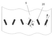
- FIG. 3 is a view (a developed view of the housing 5) for explaining the laser welding portion 20 according to the present embodiment.
- the laser welds 20 are formed at predetermined intervals in the circumferential direction of the housing 5. In the present embodiment, six laser welds 20 are provided. In addition, the mutual space
- the width of the laser welded portion 20 is preferably twice or more the thickness of the electromagnetic steel sheet.
- the width of the laser welded portion 20 By setting the width of the laser welded portion 20 to be twice or more the thickness of the electromagnetic steel sheet, the penetration depth into the stator 10 can be suppressed, and the efficiency reduction of the motor portion 2 can be prevented.
- the width of the laser weld 20 is, for example, 0.5 mm to 3 mm.
- the laser welding portion 20 in the present embodiment is formed over a predetermined length in the axial direction of the housing 5. That is, the laser welding portion 20 is linear.
- the laser welding portion 20 is formed at a point like the welding point in the conventional spot welding, the local distortion in the stator 10 is large because it is necessary to irradiate the laser at a high temperature and high temperature locally. Become.
- the laser welded portion 20 since the laser welded portion 20 has a predetermined length, laser irradiation at relatively low temperature and low temperature is possible, and local deformation of the stator 10 can be prevented.
- the figure which shows the relationship between the motor part 2 and the housing 5 in this Embodiment in FIG. 4 is shown.
- A is preferably 10% or more and 90% or less of B.
- the laser welded portion 20 is formed at a position exceeding 5% of the axial length B of the stator core 22 in the axial direction of the stator core 22 from the end face of the stator core 22.
- the welding strength is insufficient.
- the length A of the laser weld 20 exceeds 90% of the axial length B of the stator core 22 or from the end face of the stator core 22 in the axial direction of the stator core 22
- sparks generated when welding the stator 10 and the housing 5 are the upper and lower ends of the stator core 22. There is a risk that it may protrude into the housing 5.
- the length A of the laser welded portion 20 is preferably 10% or more and 20% or less of the axial length B of the stator core 22.
- the welding range can be made smaller, and deformation of the stator 10 generated at the time of laser welding can be more effectively prevented.
- the length of the laser weld 20 is about 10 to 20 mm, and the length of the stator core 22 is about 60 mm.
- the length of the laser welding part 20 means welding distance.
- the length of the laser weld 20 is A shown in FIG.
- all of the plurality of laser welds 20 have the same length, and laser welds 20 of different lengths may be included.
- torque in the circumferential direction is dispersed at the same height. Therefore, the rotational torque generated in the stator 10 is not received as a moment force in the axial direction, and the vibration of the stator 10 can be suppressed.
- the laser welds 20 in the present embodiment are formed at the same height in the axial direction of the housing 5. As a result, it becomes possible to evenly disperse and hold the torque fluctuation generated by the compression mechanism section 3 and the torque fluctuation generated by the rotation of the motor section 2 by the plurality of laser welding sections 20.
- the same height does not necessarily mean exactly the same, and includes a state of being somewhat deviated within the range where the above-mentioned effect is exerted.
- the fact that the housing 5 is formed at the same height in the axial direction can be rephrased as starting points in the housing 5 of the laser welding are made the same height.
- Modification 1 The modification 1 of the laser welding part 20 which concerns on this Embodiment is shown in FIG.
- the plurality of laser welded parts 20A are formed at different heights in the axial direction of the housing 5.
- the distortion of the magnetic field generated during high-speed rotation of the motor unit 2 and the axial vibration generated by the moment force of the rotating torque are held by the laser welds 20A of different heights. Distortion and vibration can be suppressed.
- a plurality of laser welds 20 are formed, and the laser welds 20 are formed at positions spaced 180 degrees apart in the circumferential direction. Thereby, the distortion of the outer peripheral direction by laser welding can be offset.
- the laser welding portion 20 in the present embodiment is formed to be inclined with respect to the axial direction of the housing 5.
- the welding range can be expanded with respect to the circumferential direction of the housing 5, and the torque fluctuation received by the stator 10 at the time of compression and the torque fluctuation generated by the rotation of the motor unit 2 can be equalized with the plurality of laser welds 20. It becomes possible to disperse and hold.
- the inclination ⁇ of the laser welding portion 20 is inclined in the range of 10 degrees to 30 degrees with respect to the axial direction of the housing 5.
- all six laser welding parts 20 do not need to be inclined and formed.
- adjacent laser welds 20 are formed to be inclined in the opposite direction with respect to the axial direction of the housing 5.
- the distance between the ends of the adjacent laser welds 20 can be shortened, and the circumferential rigidity of the housing 5 can be enhanced.
- welding can be performed while rotating the housing 5, the time required for welding can be shortened.
- Modification 2 The modification 2 of the laser welding part 20 which concerns on this Embodiment is shown in FIG.
- a plurality of laser welded portions 20B are formed in parallel with the axial direction of the housing 5. With this configuration, since the laser welded portion 20B can be made longer in the axial direction of the stator 10, distortion and vibration of the stator 10 can be suppressed.
- FIG. 7 is a view for explaining the distance between the end portions of each of the laser welds 20 and 20B according to the embodiment of the present invention and the second modification.
- the distance (W) between the ends of the laser weld 20 in the embodiment is smaller than the distance (W ′) between the ends of the laser weld 20B according to the second modification (W ⁇ W ′).
- the present invention is not limited to the configuration of the embodiment, and various changes can be made within the scope of the present invention, and the present invention can be implemented in the following other embodiments.
- the embodiment shows an example in which the present invention is applied to a two-piston rotary compressor. However, the present invention can also be practiced with a one-piston rotary compressor. Moreover, it is applicable not only to a rotary compressor but, for example, to a scroll compressor.
- the example in which six laser welding parts 20 were formed was shown in embodiment, it is not restricted to six. It is only necessary to form a plurality.
- the embodiment shows an example in which the distributed winding type motor unit 2 is implemented, but the concentrated winding type motor unit 2 can also implement the present invention.
- the embodiment shows an example in which the stator 10 and the housing 5 are fixed by laser welding, but first, the motor portion 2 is inserted into the cylindrical housing 5 by shrink fitting, After the clearance dimension with the rotor 11 is determined, welding and fixing may be performed by laser welding.
- FIG. 8 is a cross-sectional photograph of the main part of the compressor 100 according to the present invention.
- FIG. 8 shows a laser weld 20 formed by a fiber laser.
- the laser welding portion 20 includes the housing 5 and the stator 10 so that the focusing point 20 a of the fiber laser is at the position of the stator 10 instead of the boundary position between the housing 5 and the stator 10.
- Are formed across the A recess is formed on the outer wall of the housing 5 irradiated by the fiber laser.
- the focusing point 20a of the fiber laser is a boundary position between the housing 5 and the stator 10
- the spot size is small in the fiber laser and welding is performed. It may be insufficient.
- the stator 10 is melted to fill the gap and the housing 5 is completed. Welded with.
- the stator 10 is preferably fitted to the housing 5 before the laser welding portion 20 is formed. By eliminating the gap between the housing 5 and the stator 10 in advance by means of the intermediate fitting, welding at the laser welding portion 20 can be performed reliably.
- the efficiency of the compressor can be enhanced by preventing the deformation and distortion of the motor unit.
- it is applicable also to uses, such as a heat pump type hot-water heater other than the compressor for air conditioners.
Landscapes
- Engineering & Computer Science (AREA)
- Mechanical Engineering (AREA)
- General Engineering & Computer Science (AREA)
- Power Engineering (AREA)
- Physics & Mathematics (AREA)
- Optics & Photonics (AREA)
- Plasma & Fusion (AREA)
- Manufacturing & Machinery (AREA)
- Compressor (AREA)
- Iron Core Of Rotating Electric Machines (AREA)
- Applications Or Details Of Rotary Compressors (AREA)
Abstract
Description
これにより、電動機部の高効率化、圧縮機の外周面を被覆する被覆材(断熱材、防音材、蓄熱材等)の保護を実現することができる。
これにより、固定子の変形による電動機部の効率低下を防止することができる。また、レーザ溶接部が所定の長さを有するので比較的低温・低熱でのレーザ照射が可能となり、局所的な固定子の変形を防止することができる。
スロットの径方向の外側となる位置にレーザ溶接部を形成することで、冷媒通路となる空隙を、ヨーク部の外周面に幅広く形成することが可能となる。よって、レーザ溶接部や空隙による電動機部の効率低下を防止することができる。
ヨーク部に冷媒通路となる冷媒通路孔を形成することで、ティース部の径方向の外側となるヨーク部に冷媒通路孔を形成することができる。また、冷媒通路孔を形成できるため、空隙を狭くでき、電動機部の効率低下を防止することができる。
ファイバーレーザを用いることで溶接時の熱影響が少なく、ファイバーレーザの集光点を、ハウジングと固定子との境界位置ではなく、固定子とすることで小さなスポットサイズで確実に溶接することができる。
これにより、レーザ溶接点に盛り上がり(凸部)が生じないので、圧縮機の外周面を被覆する被覆材(断熱材、防音材、蓄熱材等)の破損を防止することができる。
レーザ溶接部の長さが固定子コアの軸方向長さの10%を下回ると溶接強度が不足する。また、レーザ溶接部の長さが固定子コアの軸方向長さの90%を越える、又は、固定子コアの端面から固定子コアの軸方向に、固定子コアの軸方向長さの5%の長さの範囲内の位置にレーザ溶接部が形成されると、固定子とハウジングを溶接する際に発生する火花が、固定子コアの上下端からハウジング内にはみ出すおそれがある。
レーザ溶接部の長さを、固定子コアの軸方向長さの20%以下とすることで、レーザを照射する範囲を減らして溶接時に発生する固定子の変形を効果的に防止することができる。
これにより、圧縮機構部により発生するトルク変動と、電動機部の回転により発生するトルク変動とを、複数のレーザ溶接部で均等に分散して保持することができる。
これにより、モータの高速回転時に発生する磁界の歪みと、回転トルクのモーメント力により発生する軸方向の振動とを、異なる高さのレーザ溶接部で保持することにより、固定子の歪み及び振動を抑えることができる。
これにより、固定子の軸方向におけるレーザ溶接部を長くできるため、固定子の歪み及び振動を抑えることができる。
これにより、ハウジング円周方向に関して溶接範囲を広げることができ、圧縮時に固定子が受けるトルク変動と電動機部の回転により発生するトルク変動とを、複数の溶接部で均等に分散して保持することができる。
これにより、隣接するレーザ溶接部間の距離を部分的に短くすることができ、ハウジングの円周方向の剛性を高めることができる。また、ハウジングを回転させながら溶接を行えるため、溶接に要する時間を短縮できる。
これにより、レーザ溶接による外周方向の歪を相殺することが可能となる。
これにより、固定子内部への溶け込み深さを抑え、電動機部の効率低下を防止することができる。
これにより、冷媒循環量が10%程度増え、負荷トルクが増加しても効率を低下させず、電動機部の騒音や振動を従来の冷媒使用時と同等以下に抑制できる。
中間ばめによってハウジングと固定子との隙間を無くすことができるため、レーザ溶接部での溶接を確実に行える。
図1は、本発明の一実施の形態における圧縮機100の縦断面図である。圧縮機100は、密閉容器1、電動機部2、圧縮機構部3及び駆動軸4を備えている。密閉容器1は、円筒状のハウジング5と、このハウジング5の開口を閉塞する上部カバー6及び下部カバー7とから構成されている。圧縮機構部3は、ハウジング5の下部に配置されている。電動機部2は、ハウジング5の内部において、圧縮機構部3の上に配置されている。駆動軸4によって、圧縮機構部3と電動機部2とが連結されている。上部カバー6には、電動機部2に電力を供給するための端子8が設けられている。密閉容器1の底部には、潤滑用のオイルを保持するためのオイル溜まり9が形成されている。電動機部2は、固定子10及び回転子11で構成されている。固定子10は、ハウジング5の内壁に固定されている。回転子11は、駆動軸4に固定されており、かつ駆動軸4とともに回転する。駆動軸4は、上軸受部材12と下軸受部材13とにより回転自在に両端が支持されている。
また、圧縮機100の液圧縮を防止するため、アキュームレータ18が設けられている。アキュームレータ18は、圧縮機100に冷媒ガスを直接吸入する前に、冷媒ガスを気液分離させる。アキュームレータ18は、円筒状のケース19と、ケース19の上部に接続される冷媒ガス導入管と、ケース19の下部に接続される二本の冷媒ガス導出管とで構成される。
このように構成された圧縮機100において、電動機部2の固定子10とハウジング5とは、ファイバーレーザによるレーザ照射によって溶接固定されている。
図2に示すように、電動機部2には、巻線方式を分布巻きとした直流IPMモータが適している。電動機部2は、ハウジング5の内壁面に固定された固定子10と、シャフトに回転動力を伝える回転子11とからなる。
固定子10は、固定子コア22と巻線25とを有する。
固定子コア22は、金属材料からなる複数の電磁鋼板を積層して形成される。
固定子コア22は、環状のヨーク部22Aと、ヨーク部22Aから径方向の内側に突出するティース部22Bと、隣接するティース部22Bの間に形成されるスロット23と、ティース部22Bの内側に形成されて回転子11が配置される貫通孔22Cとを有する。スロット23には巻線25との絶縁性を保持する為に絶縁紙(図示せず)が挿入されている。
固定子10とハウジング5とは、6個のレーザ溶接部20によって固定されている。
レーザ溶接部20は、隣接する空隙24Aの間であって、スロット23の径方向の外側となる位置に形成している。レーザ溶接部20は、ファイバーレーザの集光点が固定子10の位置となるように形成される。ファイバーレーザを用いることで溶接時の熱影響が少ない。ファイバーレーザの集光点を、ハウジング5と固定子10との境界位置ではなく、固定子10とすることで、小さなスポットサイズで確実に溶接することができる。
なお、レーザ溶接部20の幅は、電磁鋼板の板厚の2倍以上とすることが好ましい。レーザ溶接部20の幅を、電磁鋼板の板厚の2倍以上とすることで、固定子10内部への溶け込み深さを抑え、電動機部2の効率低下を防止することができる。レーザ溶接部20の幅は、例えば0.5mm~3mmが適している。
本実施の形態におけるレーザ溶接部20は、ハウジング5の軸方向に所定の長さに渡って形成されている。すなわち、レーザ溶接部20は線状である。従来のスポット溶接における溶接点のように、レーザ溶接部20を点で形成した場合には、局所的に高温、高熱のレーザを照射する必要があるため、固定子10における局所的な歪が大きくなる。本実施の形態では、レーザ溶接部20は所定の長さを有するので、比較的低温・低熱でのレーザ照射が可能となり、局所的な固定子10の変形を防止することができる。
また、固定子コア22の端面から固定子コア22の軸方向に、固定子コア22の軸方向長さBの5%の長さを超えた位置にレーザ溶接部20を形成する。
また、レーザ溶接部20の長さAが固定子コア22の軸方向長さBの10%を下回ると、溶接強度が不足する。
また、レーザ溶接部20の長さAが固定子コア22の軸方向長さBの90%を越える、又は、固定子コア22の端面から固定子コア22の軸方向に、固定子コア22の軸方向長さBの5%の長さの範囲内の位置にレーザ溶接部20が形成されると、固定子10とハウジング5を溶接する際に発生する火花が、固定子コア22の上下端からハウジング5内にはみ出すおそれがある。
本実施の形態におけるレーザ溶接部20は、ハウジング5の軸方向に同じ高さに形成されている。これにより、圧縮機構部3により発生するトルク変動と、電動機部2の回転により発生するトルク変動とを、複数のレーザ溶接部20で均等に分散して保持することが可能となる。なお、「同じ高さ」とは、必ずしも厳密に同一を意味するのではなく、上記作用効果を奏する範囲内で、多少ずれている状態も含む。ハウジング5の軸方向に同じ高さに形成されているとは、レーザ溶接のハウジング5における開始点を、同じ高さにすると言い換えることができる。
本実施の形態に係るレーザ溶接部20の変形例1を図5に示す。本変形例では、複数のレーザ溶接部20Aがハウジング5の軸方向に違う高さに形成されている。この構成により、電動機部2の高速回転時に発生する磁界の歪みと回転トルクのモーメント力により発生する軸方向の振動とを、異なる高さのレーザ溶接部20Aで保持することにより、固定子10の歪み及び振動を抑えることができる。
レーザ溶接部20は複数個形成され、レーザ溶接部20は互いに円周方向に180度間隔をおいた位置に形成されている。これにより、レーザ溶接による外周方向の歪を相殺することができる。
本実施の形態におけるレーザ溶接部20は、ハウジング5の軸方向に対して、傾斜して形成されている。これにより、ハウジング5の円周方向に関して溶接範囲を広げることができ、圧縮時の固定子10が受けるトルク変動と電動機部2の回転により発生するトルク変動とを複数のレーザ溶接部20で均等に分散して保持することが可能となる。実用的には、レーザ溶接部20の傾きθは、ハウジング5の軸方向に対して、10度以上30度以下の範囲で傾斜している。なお、6個全てのレーザ溶接部20が全て傾斜して形成されていなくてもよい。
隣接するレーザ溶接部20同士で、ハウジング5の軸方向を基準に反対の方向に傾斜して形成されていることが好ましい。その理由の詳細については後述するが、隣接するレーザ溶接部20の端部間の距離を短くすることができ、ハウジング5の円周方向の剛性を高めることができる。また、ハウジング5を回転させながら溶接を行えるため、溶接に要する時間を短縮できる。
本実施の形態に係るレーザ溶接部20の変形例2を図6に示す。本変形例では、複数のレーザ溶接部20Bがハウジング5の軸方向に平行に形成されている。この構成により、固定子10の軸方向においてレーザ溶接部20Bを長くできるため、固定子10の歪み及び振動を抑えることが可能となる。
(1)実施の形態では、2ピストンのロータリ式圧縮機に実施した例を示したが、1ピストンのロータリ式圧縮機においても本願発明を実施することができる。また、ロータリ式圧縮機に限らず、例えばスクロール式圧縮機にも適用できる。
(2)実施の形態では、レーザ溶接部20が6個形成されている例を示したが、6個に限られるものではない。複数個形成されていればよい。
(3)実施の形態では、分布巻き式の電動機部2に実施した例を示したが、集中巻き式の電動機部2においても本願発明を実施することができる。
(4)実施の形態では、固定子10とハウジング5とをレーザ溶接で固定する例を示したが、まず、円筒状のハウジング5に電動機部2を焼きばめにより挿入し、固定子10と回転子11との隙間寸法を確定した後に、レーザ溶接により溶接固定を行ってもよい。
図8では、ファイバーレーザによって形成したレーザ溶接部20を示している。
図8に示すように、ファイバーレーザの集光点20aが、ハウジング5と固定子10との境界位置ではなく固定子10の位置となるように、レーザ溶接部20は、ハウジング5と固定子10とに跨って形成される。
ファイバーレーザが照射したハウジング5の外壁には凹部が形成される。
ファイバーレーザの集光点20aを、ハウジング5と固定子10との境界位置とすると、ハウジング5と固定子10とに隙間を生じている場合には、ファイバーレーザではスポットサイズが小さいために溶接が不十分となる可能性がある。これに対して、ファイバーレーザの集光点20aを固定子10とすることで、仮にハウジング5と固定子10とに隙間を生じていても、固定子10が溶融して隙間を埋めてハウジング5と溶接される。
なお、ハウジング5と固定子10との間で隙間を生じさせないために、レーザ溶接部20を形成する前に、ハウジング5に固定子10を中間ばめすることが好ましい。中間ばめによってハウジング5と固定子10との隙間をあらかじめ無くすことで、レーザ溶接部20での溶接を確実に行える。
2 電動機部
3 圧縮機構部
4 駆動軸
5 ハウジング
6 上部カバー
7 下部カバー
8 端子
9 オイル溜まり
10 固定子
11 回転子
12 上軸受部材
13 下軸受部材
14 駆動軸偏心部
15 シリンダ
16 ローリングピストン
17 吐出管
18 アキュームレータ
19 ケース
20 レーザ溶接部
20a 集光点
21 マフラカバー
22 固定子コア
22A ヨーク部
22B ティース部
23 スロット
24A 空隙
24B 冷媒通路孔
25 巻線
100 圧縮機
Claims (16)
- 固定子と前記固定子の内側に配設されている回転子とからなる電動機部と、圧縮機構部と、ハウジングとを備え、
前記固定子は前記ハウジングの内壁に複数のレーザ溶接部によって固定されており、
複数の前記レーザ溶接部を、前記ハウジングの円周方向に互いに所定の間隔をおいて形成し、
それぞれの前記レーザ溶接部を、所定の長さに渡って形成したことを特徴とする圧縮機。 - 前記固定子が、固定子コアと巻線とを有し、
前記固定子コアが、金属材料からなる複数の電磁鋼板を積層して形成され、
前記固定子コアが、環状のヨーク部と、前記ヨーク部から径方向の内側に突出するティース部と、隣接する前記ティース部の間に形成されるスロットとを有し、
前記ヨーク部の外周面には、冷媒通路となる複数の空隙を形成し、
隣接する前記空隙の間であって、前記スロットの径方向の外側となる位置に、前記レーザ溶接部を形成したことを特徴とする請求項1に記載の圧縮機。 - 隣接する前記空隙の間であって、前記ティース部の径方向の外側となる前記ヨーク部に、前記冷媒通路となる冷媒通路孔を形成したことを特徴とする請求項2に記載の圧縮機。
- 前記レーザ溶接部を、ファイバーレーザによって形成し、
前記ファイバーレーザの集光点を前記固定子としたことを特徴とする請求項1から請求項3のいずれかに記載の圧縮機 - 前記レーザ溶接部の形成によって、前記ハウジングの外壁には凹部が形成されることを特徴とする請求項1から請求項4のいずれかに記載の圧縮機。
- 前記レーザ溶接部の長さを、前記固定子コアの軸方向長さの10%以上90%以下とし、
前記固定子コアの端面から前記固定子コアの前記軸方向に、前記固定子コアの前記軸方向長さの5%の長さを超えた位置に前記レーザ溶接部を形成したことを特徴とする請求項1から請求項5のいずれかに記載の圧縮機。 - 前記レーザ溶接部の長さを、前記固定子コアの前記軸方向長さの10%以上20%以下としたことを特徴とする請求項6に記載の圧縮機。
- 複数の前記レーザ溶接部を、前記ハウジングの軸方向に同じ高さに形成したことを特徴とする請求項1から請求項7のいずれかに記載の圧縮機。
- 複数の前記レーザ溶接部を、前記ハウジングの軸方向に異なる高さに形成したことを特徴とする請求項1から請求項7のいずれかに記載の圧縮機。
- 前記レーザ溶接部を、前記ハウジングの軸方向に対して平行に形成したことを特徴とする請求項1から請求項9のいずれかに記載の圧縮機。
- 前記レーザ溶接部を、前記ハウジングの軸方向に対して傾斜して形成したことを特徴とする請求項1から請求項9のいずれかに記載の圧縮機。
- 第1のレーザ溶接部と、前記第1のレーザ溶接部と円周方向に隣接して配置された第2のレーザ溶接部とは、前記ハウジングの前記軸方向に対する傾斜方向を反対としたことを特徴とする請求項11に記載の圧縮機。
- 複数の前記レーザ溶接部の中の任意の第3のレーザ溶接部から円周方向に180度間隔をおいた位置には、第4のレーザ溶接部を形成したことを特徴とする請求項1から請求項12のいずれかに記載の圧縮機。
- 前記レーザ溶接部の幅を、前記電磁鋼板の板厚の2倍以上としたことを特徴とする請求項2又は請求項3に記載の圧縮機。
- 前記圧縮機構部で圧縮する冷媒としてHFC冷媒R32を用いることを特徴とする請求項1から請求項14のいずれかに記載の圧縮機。
- 前記ハウジングに前記固定子を中間ばめした後に、前記レーザ溶接部を形成することを特徴とする請求項1から請求項15のいずれかに記載の圧縮機。
Priority Applications (3)
| Application Number | Priority Date | Filing Date | Title |
|---|---|---|---|
| JP2015535284A JP6222583B2 (ja) | 2013-09-05 | 2014-03-11 | 圧縮機 |
| EP14841598.7A EP3043069B8 (en) | 2013-09-05 | 2014-03-11 | Compressor |
| CN201480048193.6A CN105556122B (zh) | 2013-09-05 | 2014-03-11 | 压缩机 |
Applications Claiming Priority (10)
| Application Number | Priority Date | Filing Date | Title |
|---|---|---|---|
| JP2013183829 | 2013-09-05 | ||
| JP2013-183829 | 2013-09-05 | ||
| JP2013-193823 | 2013-09-19 | ||
| JP2013193823 | 2013-09-19 | ||
| JP2013196428 | 2013-09-24 | ||
| JP2013-196428 | 2013-09-24 | ||
| JP2013-212471 | 2013-10-10 | ||
| JP2013212471 | 2013-10-10 | ||
| JP2013-226269 | 2013-10-31 | ||
| JP2013226269 | 2013-10-31 |
Publications (1)
| Publication Number | Publication Date |
|---|---|
| WO2015033488A1 true WO2015033488A1 (ja) | 2015-03-12 |
Family
ID=52627992
Family Applications (1)
| Application Number | Title | Priority Date | Filing Date |
|---|---|---|---|
| PCT/JP2014/001376 WO2015033488A1 (ja) | 2013-09-05 | 2014-03-11 | 圧縮機 |
Country Status (4)
| Country | Link |
|---|---|
| EP (1) | EP3043069B8 (ja) |
| JP (1) | JP6222583B2 (ja) |
| CN (1) | CN105556122B (ja) |
| WO (1) | WO2015033488A1 (ja) |
Cited By (5)
| Publication number | Priority date | Publication date | Assignee | Title |
|---|---|---|---|---|
| JP2015075047A (ja) * | 2013-10-10 | 2015-04-20 | パナソニックIpマネジメント株式会社 | 圧縮機 |
| WO2016185560A1 (ja) * | 2015-05-19 | 2016-11-24 | 三菱電機株式会社 | 回転電機 |
| CN106670667A (zh) * | 2017-01-23 | 2017-05-17 | 广东顺德三合工业自动化设备股份有限公司 | 一种用于焊接压缩机与储液器的自动化生产线 |
| JP2017180123A (ja) * | 2016-03-28 | 2017-10-05 | 株式会社富士通ゼネラル | ロータリ圧縮機 |
| CN113798762A (zh) * | 2021-10-19 | 2021-12-17 | 湖北锐仕拓机电设备有限公司 | 一种壳体结构件的焊接工装及焊接方法 |
Families Citing this family (4)
| Publication number | Priority date | Publication date | Assignee | Title |
|---|---|---|---|---|
| JP6377104B2 (ja) * | 2016-07-15 | 2018-08-22 | 三菱重工業株式会社 | モータおよびモータ搭載機器 |
| CN109458334A (zh) * | 2017-09-06 | 2019-03-12 | 上海海立电器有限公司 | 压缩机及其制造方法 |
| CN110076513B (zh) * | 2019-04-22 | 2021-10-08 | 广东美的智能机器人有限公司 | 焊接设备、具有其的生产线及焊接方法 |
| WO2023187440A1 (en) * | 2022-03-29 | 2023-10-05 | Siam Compressor Industry Co., Ltd. | A compressor |
Citations (10)
| Publication number | Priority date | Publication date | Assignee | Title |
|---|---|---|---|---|
| JPS59126564U (ja) * | 1983-02-15 | 1984-08-25 | 三菱電機株式会社 | キヤンド式電動機 |
| JPS63189685A (ja) | 1987-01-30 | 1988-08-05 | Sanyo Electric Co Ltd | 密閉型回転圧縮機 |
| JPH05227685A (ja) * | 1991-11-26 | 1993-09-03 | Toshiba Corp | 回転電機 |
| JP2001304123A (ja) * | 2000-04-27 | 2001-10-31 | Mitsubishi Electric Corp | 密閉型圧縮機およびその製造方法、冷凍・空調装置。 |
| JP2007268609A (ja) * | 2006-03-07 | 2007-10-18 | Daikin Ind Ltd | 圧縮機の製造方法 |
| JP2010011645A (ja) * | 2008-06-27 | 2010-01-14 | Daikin Ind Ltd | 積層鉄心、モータ及び圧縮機 |
| JP2010023048A (ja) * | 2008-07-15 | 2010-02-04 | Nisshin Steel Co Ltd | 自動車用排気管の製造方法 |
| JP2010041851A (ja) * | 2008-08-06 | 2010-02-18 | Daikin Ind Ltd | 固定子とケーシングとの固定構造及びそれを備えた圧縮機 |
| JP2011050151A (ja) * | 2009-08-26 | 2011-03-10 | Aichi Elec Co | 電動機および圧縮機 |
| JP2013162676A (ja) * | 2012-02-07 | 2013-08-19 | Daikin Ind Ltd | 電動機および圧縮機 |
Family Cites Families (4)
| Publication number | Priority date | Publication date | Assignee | Title |
|---|---|---|---|---|
| KR100565264B1 (ko) * | 2005-01-13 | 2006-03-30 | 엘지전자 주식회사 | 왕복동식 압축기의 외측고정자 고정장치 |
| JP4241849B2 (ja) * | 2007-04-02 | 2009-03-18 | ダイキン工業株式会社 | 圧縮機 |
| JP2011055576A (ja) * | 2009-08-31 | 2011-03-17 | Daikin Industries Ltd | 圧縮機 |
| KR20110114367A (ko) * | 2010-04-13 | 2011-10-19 | 엘지전자 주식회사 | 밀폐형 압축기 |
-
2014
- 2014-03-11 JP JP2015535284A patent/JP6222583B2/ja active Active
- 2014-03-11 EP EP14841598.7A patent/EP3043069B8/en active Active
- 2014-03-11 WO PCT/JP2014/001376 patent/WO2015033488A1/ja active Application Filing
- 2014-03-11 CN CN201480048193.6A patent/CN105556122B/zh active Active
Patent Citations (10)
| Publication number | Priority date | Publication date | Assignee | Title |
|---|---|---|---|---|
| JPS59126564U (ja) * | 1983-02-15 | 1984-08-25 | 三菱電機株式会社 | キヤンド式電動機 |
| JPS63189685A (ja) | 1987-01-30 | 1988-08-05 | Sanyo Electric Co Ltd | 密閉型回転圧縮機 |
| JPH05227685A (ja) * | 1991-11-26 | 1993-09-03 | Toshiba Corp | 回転電機 |
| JP2001304123A (ja) * | 2000-04-27 | 2001-10-31 | Mitsubishi Electric Corp | 密閉型圧縮機およびその製造方法、冷凍・空調装置。 |
| JP2007268609A (ja) * | 2006-03-07 | 2007-10-18 | Daikin Ind Ltd | 圧縮機の製造方法 |
| JP2010011645A (ja) * | 2008-06-27 | 2010-01-14 | Daikin Ind Ltd | 積層鉄心、モータ及び圧縮機 |
| JP2010023048A (ja) * | 2008-07-15 | 2010-02-04 | Nisshin Steel Co Ltd | 自動車用排気管の製造方法 |
| JP2010041851A (ja) * | 2008-08-06 | 2010-02-18 | Daikin Ind Ltd | 固定子とケーシングとの固定構造及びそれを備えた圧縮機 |
| JP2011050151A (ja) * | 2009-08-26 | 2011-03-10 | Aichi Elec Co | 電動機および圧縮機 |
| JP2013162676A (ja) * | 2012-02-07 | 2013-08-19 | Daikin Ind Ltd | 電動機および圧縮機 |
Cited By (9)
| Publication number | Priority date | Publication date | Assignee | Title |
|---|---|---|---|---|
| JP2015075047A (ja) * | 2013-10-10 | 2015-04-20 | パナソニックIpマネジメント株式会社 | 圧縮機 |
| WO2016185560A1 (ja) * | 2015-05-19 | 2016-11-24 | 三菱電機株式会社 | 回転電機 |
| US10637308B2 (en) | 2015-05-19 | 2020-04-28 | Mitsubishi Electric Corporation | Rotary electrical machine including an armature core |
| JP2017180123A (ja) * | 2016-03-28 | 2017-10-05 | 株式会社富士通ゼネラル | ロータリ圧縮機 |
| CN107237751A (zh) * | 2016-03-28 | 2017-10-10 | 富士通将军股份有限公司 | 旋转式压缩机 |
| CN107237751B (zh) * | 2016-03-28 | 2020-04-24 | 富士通将军股份有限公司 | 旋转式压缩机 |
| CN106670667A (zh) * | 2017-01-23 | 2017-05-17 | 广东顺德三合工业自动化设备股份有限公司 | 一种用于焊接压缩机与储液器的自动化生产线 |
| CN113798762A (zh) * | 2021-10-19 | 2021-12-17 | 湖北锐仕拓机电设备有限公司 | 一种壳体结构件的焊接工装及焊接方法 |
| CN113798762B (zh) * | 2021-10-19 | 2023-12-29 | 湖北锐仕拓机电设备有限公司 | 一种壳体结构件的焊接工装及焊接方法 |
Also Published As
| Publication number | Publication date |
|---|---|
| CN105556122B (zh) | 2018-04-06 |
| EP3043069B1 (en) | 2021-01-13 |
| JP6222583B2 (ja) | 2017-11-01 |
| EP3043069A1 (en) | 2016-07-13 |
| JPWO2015033488A1 (ja) | 2017-03-02 |
| EP3043069B8 (en) | 2021-03-17 |
| EP3043069A4 (en) | 2016-08-31 |
| CN105556122A (zh) | 2016-05-04 |
Similar Documents
| Publication | Publication Date | Title |
|---|---|---|
| WO2015033488A1 (ja) | 圧縮機 | |
| WO2015056364A1 (ja) | 圧縮機 | |
| US11437877B2 (en) | Rotor, motor, compressor, and air conditioner | |
| JP4841536B2 (ja) | モータ及びそれを備えた冷媒圧縮機 | |
| JP2011055576A (ja) | 圧縮機 | |
| CN108953146B (zh) | 一种循环油冷的罗茨泵 | |
| JP6230441B2 (ja) | 単相誘導電動機、密閉型圧縮機及び冷凍サイクル装置 | |
| EP3324515B1 (en) | Rotor, electric motor, compressor, and refrigerator/air conditioning equipment | |
| JP6024233B2 (ja) | タービン発電機 | |
| JP2015075047A (ja) | 圧縮機 | |
| KR101166306B1 (ko) | 응력완화부를 갖는 고정자 및 그를 포함하는 압축기 | |
| US20220294280A1 (en) | Compressor | |
| JP2015071971A (ja) | 圧縮機 | |
| JP5135779B2 (ja) | 圧縮機 | |
| JP4858565B2 (ja) | 圧縮機 | |
| JP2008138591A5 (ja) | ||
| JP2007285180A (ja) | 回転式圧縮機、これを用いた冷凍サイクル装置 | |
| JP7436908B2 (ja) | 回転電気機械、圧縮機、および冷凍装置 | |
| JP2019085953A (ja) | 圧縮機 | |
| JP7042455B2 (ja) | 圧縮機 | |
| JP2010037973A (ja) | ロータリ圧縮機 | |
| JP7134327B2 (ja) | 密閉型圧縮機 | |
| JP5506269B2 (ja) | 密閉型電動圧縮機 | |
| JP2008169743A (ja) | 圧縮機 | |
| KR20160013635A (ko) | 로터리 압축기 및 그 제조방법 |
Legal Events
| Date | Code | Title | Description |
|---|---|---|---|
| WWE | Wipo information: entry into national phase |
Ref document number: 201480048193.6 Country of ref document: CN |
|
| 121 | Ep: the epo has been informed by wipo that ep was designated in this application |
Ref document number: 14841598 Country of ref document: EP Kind code of ref document: A1 |
|
| ENP | Entry into the national phase |
Ref document number: 2015535284 Country of ref document: JP Kind code of ref document: A |
|
| NENP | Non-entry into the national phase |
Ref country code: DE |
|
| REEP | Request for entry into the european phase |
Ref document number: 2014841598 Country of ref document: EP |
|
| WWE | Wipo information: entry into national phase |
Ref document number: 2014841598 Country of ref document: EP |