WO2015030007A1 - 非空気入りタイヤ - Google Patents
非空気入りタイヤ Download PDFInfo
- Publication number
- WO2015030007A1 WO2015030007A1 PCT/JP2014/072325 JP2014072325W WO2015030007A1 WO 2015030007 A1 WO2015030007 A1 WO 2015030007A1 JP 2014072325 W JP2014072325 W JP 2014072325W WO 2015030007 A1 WO2015030007 A1 WO 2015030007A1
- Authority
- WO
- WIPO (PCT)
- Prior art keywords
- tire
- diameter
- rim
- ratio
- range
- Prior art date
- Legal status (The legal status is an assumption and is not a legal conclusion. Google has not performed a legal analysis and makes no representation as to the accuracy of the status listed.)
- Ceased
Links
Images

Classifications
-
- B—PERFORMING OPERATIONS; TRANSPORTING
- B60—VEHICLES IN GENERAL
- B60C—VEHICLE TYRES; TYRE INFLATION; TYRE CHANGING; CONNECTING VALVES TO INFLATABLE ELASTIC BODIES IN GENERAL; DEVICES OR ARRANGEMENTS RELATED TO TYRES
- B60C3/00—Tyres characterised by the transverse section
- B60C3/04—Tyres characterised by the transverse section characterised by the relative dimensions of the section, e.g. low profile
-
- B—PERFORMING OPERATIONS; TRANSPORTING
- B60—VEHICLES IN GENERAL
- B60C—VEHICLE TYRES; TYRE INFLATION; TYRE CHANGING; CONNECTING VALVES TO INFLATABLE ELASTIC BODIES IN GENERAL; DEVICES OR ARRANGEMENTS RELATED TO TYRES
- B60C5/00—Inflatable pneumatic tyres or inner tubes
- B60C5/007—Inflatable pneumatic tyres or inner tubes made from other material than rubber
-
- B—PERFORMING OPERATIONS; TRANSPORTING
- B60—VEHICLES IN GENERAL
- B60C—VEHICLE TYRES; TYRE INFLATION; TYRE CHANGING; CONNECTING VALVES TO INFLATABLE ELASTIC BODIES IN GENERAL; DEVICES OR ARRANGEMENTS RELATED TO TYRES
- B60C7/00—Non-inflatable or solid tyres
- B60C7/22—Non-inflatable or solid tyres having inlays other than for increasing resiliency, e.g. for armouring
-
- B—PERFORMING OPERATIONS; TRANSPORTING
- B60—VEHICLES IN GENERAL
- B60C—VEHICLE TYRES; TYRE INFLATION; TYRE CHANGING; CONNECTING VALVES TO INFLATABLE ELASTIC BODIES IN GENERAL; DEVICES OR ARRANGEMENTS RELATED TO TYRES
- B60C2200/00—Tyres specially adapted for particular applications
- B60C2200/12—Tyres specially adapted for particular applications for bicycles
Definitions
- the present invention relates to a non-pneumatic tire, and more particularly, to a non-pneumatic tire that can prevent rim disengagement due to tire deformation when turning while a load is applied.
- a groove or the like is provided on the side surface of the non-pneumatic tire, and the rim is assembled by fitting the rim and the groove.
- rim disengagement is likely to occur when a lateral force is further applied by turning or the like in a state where a vertical load is applied.
- An object of the present invention is to provide a non-pneumatic tire that can prevent the rim from coming off due to tire deformation when the vehicle is turned with a load applied.
- the non-pneumatic tire of the present invention for achieving the above object is a non-pneumatic tire comprising a tread portion that contacts a road surface during traveling and a fitting portion fitted to a rim.
- a pair of left and right indentations extending continuously in the tire circumferential direction is formed, and the diameter difference D1 between the diameter r1 at the position P1 where the indentation is formed and the diameter r at the tire outermost diameter position P and the indentation
- the ratio D1 / W1 to the tire minimum width W1 at the formed position P1 is set in a range of 0.20 ⁇ D1 / W1 ⁇ 1.20, and from the bottom surface of the fitting portion at the position P1 where the recessed portion is formed.
- the ratio H1 / SH between the height H1 and the tire cross-section height SH is in the range of 0.25 ⁇ H1 / SH ⁇ 0.60, and the height H2 from the bottom surface of the fitting portion at the tire maximum width position P2 H2 / S ratio between tire and tire cross-section height SH The is characterized in that the range of 0.30 ⁇ H2 / SH ⁇ 0.65.
- the rim is prevented from coming off by meshing with the indented portion described above, but in particular, by setting the ratio D1 / W1 within the above range, the tread portion (exposed from the rim and actually used as a tire)
- the shape of the functioning elastic body is made flat and the ratio H1 / SH is set in the above range, so that the amount of the fitting portion (the portion that fits the rim) is sufficiently secured, and the ratio H2 /
- SH By setting SH within the above-described range, the center of gravity of the tire can be biased toward the rim with the portion close to the rim as the tire maximum width position P2, and rim detachment can be effectively prevented.
- the ratio W1 / W2 between the tire minimum width W1 and the tire maximum width W2 at the position P1 where the hollow portion is formed is in the range of 1.00 ⁇ W2 / W1 ⁇ 1.50.
- the ratio W1 / W2 within a predetermined range larger than 1.00, the rim width and the tire maximum width can be balanced, which is advantageous in preventing rim detachment.
- limb can fully be ensured, the effect which protects a rim
- the diameter difference D2 between the diameter r at the tire outermost diameter position P and the diameter r2 at the tire maximum width position P2 is preferably in the range of 8 mm to 20 mm.
- the average radius between the tire outermost diameter position P and the tire maximum width position P2 is preferably 8 mm to 25 mm.
- the rigidity obtained by the reinforcing member is advantageous for improving the rim detachment resistance.
- At least the tread portion is composed of a thermoplastic resin, a thermoplastic elastomer composition, a thermoreversible cross-linked elastomer composition, or a mixture thereof.
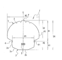
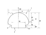
- FIG. 1 is a meridian cross-sectional view of a non-pneumatic tire according to an embodiment of the present invention.
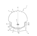
- FIG. 2 is a meridian cross-sectional view showing a state where the non-pneumatic tire of FIG. 1 is assembled to a rim.
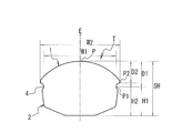
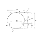
- FIG. 3 is a meridian cross-sectional view of a non-pneumatic tire according to another embodiment of the present invention.
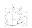
- FIG. 4 is a meridian cross-sectional view of a non-pneumatic tire according to another embodiment of the present invention.
- FIG. 5 is a meridian cross-sectional view of a non-pneumatic tire according to another embodiment of the present invention.
- FIG. 6 is a meridian cross-sectional view of a non-pneumatic tire according to another embodiment of the present invention.
- FIG. 7 is a meridian cross-sectional view showing an example of a conventional non-pneumatic tire.
- the non-pneumatic tire T includes a tread portion 1 that comes into contact with a road surface during traveling, and a fitting portion 2 that is located on the inner peripheral side of the tread portion 1 and is fitted to the rim R. As illustrated in FIG. 1, the shape of the non-pneumatic tire T is symmetrical with respect to the tire equator E.
- the tread portion 1 is a portion that is exposed from the rim R and actually functions as a tire when traveling. As illustrated in FIG. 1, the outline of the tread portion 1 in the meridian section has a smooth semicircular shape. In the embodiment of FIG. 1, a groove 3 extending in the circumferential direction is provided on the surface of the tread portion 1 (particularly, a region that contacts the road surface during use) for the purpose of obtaining drainage. Such grooves 3 may not be provided according to the purpose of use of the tire.
- the fitting part 2 is arrange
- the shape of the fitting portion 2 is determined according to the rim R, and the fitting portion 2 in the embodiment of FIG. 1 is between the side surface 2a and the bottom surface 2b so as to fit the rim R illustrated in FIG.
- the taper portion 2c is formed into a polygonal shape.
- a convex portion Rb (a portion protruding inward in the tire width direction) present at the end of the rim flange Ra of the rim R is a recessed portion 4.
- the non-pneumatic tire T is not easily detached from the rim R when the tire is used.
- the shape of the indented part 4 is not particularly limited as long as it has a shape that meshes with the convex part Rb of the rim R. However, the indented part 4 has an arc shape as shown in the figure without corners so as not to be damaged when the tire is mounted. There should be. Further, the depth may be set to 0.1 mm to 4.0 mm, for example, and the width may be set to 0.5 mm to 4.0 mm, for example.
- the diameter at the position P1 is r1
- the outermost diameter position of the tire is P
- the diameter at the position P is r
- the ratio D1 / W1 between the diameter difference D1 between the diameter r1 and the diameter r and the tire minimum width W1 at the position P1 is set in a range of 0.20 ⁇ D1 / W1 ⁇ 1.20.
- the tire minimum width W1 at the position P1 is the distance between the innermost points in the tire width direction of the left and right indentations 4 as shown in FIG.
- the ratio H1 / SH between the height H1 from the bottom surface 2b of the fitting portion 2 at the position P1 and the tire cross-section height SH is set in a range of 0.25 ⁇ H1 / SH ⁇ 0.60. ing. Further, in the present invention, the ratio H2 / SH is 0.30 ⁇ H2 / SH ⁇ 0.65, where P2 is the maximum tire width position and H2 is the height from the bottom surface 2b of the fitting portion 2 at this position P2. Is set in the range.
- the non-pneumatic tire T of the present invention has the tread portion 1 (rim R) when the ratio D1 / W1 is set in the above-described range.
- the shape of the portion of the elastic body that is exposed from the tire and actually functions as a tire becomes a flat shape, and the ratio H1 / SH is set in the above-described range, so that the fitting portion 2 (fits to the rim R).
- the portion H) is sufficiently secured, and the ratio H2 / SH is set in the above range, so that the portion near the rim R becomes the tire maximum width position P2 and the center of gravity of the tire is biased toward the rim R side.
- the fitting portion 2 is stably accommodated in the rim R, and detachment of the rim can be effectively prevented.
- the ratio D1 / W1 is smaller than 0.20, the tread portion 1 becomes too small, so that the wear life of the non-pneumatic tire T is remarkably reduced.
- the ratio D1 / W1 is greater than 1.20, the tread portion 1 becomes too large with respect to the fitting portion 2, so that the rim cannot be prevented from coming off.
- the ratio D1 / W1 is preferably set in the range of 0.30 to 1.10, more preferably 0.50 to 1.00, from the viewpoint of the balance of these effects.
- the ratio H1 / SH is preferably set in the range of 0.30 to 0.55, more preferably 0.30 to 0.50, from the viewpoint of the balance of these effects.
- the ratio H2 / SH is smaller than 0.30, the maximum width position P2 is too close to the inner peripheral side (rim R side) of the tire, and as a result, the amount of the fitting portion 2 cannot be secured. The rim cannot be prevented from coming off. Conversely, when the ratio H2 / SH is larger than 0.65, the maximum width position P2 is closer to the outer peripheral side of the tire (the contact portion side of the tread portion 1), and the center of gravity of the tire is away from the rim R side. T becomes unstable with respect to the rim R, which is disadvantageous for preventing the rim from coming off. Moreover, since the volume of the non-pneumatic tire T increases in order to make such a shape, rolling resistance deteriorates.
- the ratio H2 / SH is preferably set in the range of 0.35 to 0.60, more preferably 0.40 to 0.55 from the viewpoint of the balance of these effects.
- the tread portion 1 can be made small as illustrated in FIG. 3 or the tread portion 1 can be enlarged as illustrated in FIG. 4 according to the purpose of use. is there.
- the shape of the fitting portion 2 is tapered between the bottom surface 2b of the fitting portion 2 and the side surface 2a of the fitting portion 2 as described above.
- the shape is provided with the portion 2c.
- the shape without the tapered portion 2c can be used according to the shape of the rim, for example, as illustrated in FIG. is there.
- the indented portion 4 may be provided anywhere on the side surface 2a of the fitting portion 2, but is preferably disposed on the tire outer peripheral side (tread portion 1 side) of the side surface 2a of the fitting portion 2 as illustrated. That is, the convex portion Rb of the rim R may be formed at the end of the rim flange Ra.
- the tread portion 1 may be connected to the indented portion 4 while being smoothly curved toward the indented portion 4, but preferably, as illustrated in FIG. 1.
- the tire maximum width W2 needs to be larger than the tire minimum width W1 in order to form the indented portion 4.
- the tire minimum width W1 and the tire maximum width W2 at the position P1 where the indented portion 4 is formed are
- the ratio W1 / W2 may be set in the range of 1.00 ⁇ W2 / W1 ⁇ 1.50.
- the tire minimum width W1 (rim width) and the tire maximum width W2 can be balanced, which is advantageous in preventing rim disengagement.
- limb from a curbstone etc. can also be acquired.
- the tire maximum width W2 is preferably larger than the rim width, so the ratio W1 / W2 is preferably 1.20 to 1.50, more preferably 1. It may be set in the range of 30 to 1.40.
- the diameter difference D2 between the diameter r at the tire outermost diameter position P and the diameter r2 at the tire maximum width position P2 is preferably in the range of 8 mm to 20 mm.
- the diameter difference D2 is smaller than 8 mm, the contour line of the portion contacting the road surface of the tread portion 1 in the meridian cross section becomes linear, and the tread portion 1 approaches a square shape. It becomes difficult to improve resistance.
- the diameter difference D2 is preferably set in the range of 10 mm to 20 mm, more preferably 10 mm to 15 mm, from the viewpoint of the balance of these effects.
- the average radius between the tire outermost diameter position P and the tire maximum width position P2 is preferably 8 mm to 25 mm.
- the average radius is preferably set in the range of 10 mm to 20 mm from the viewpoint of the balance of these effects.
- a reinforcing member 5 extending in the tire circumferential direction is preferably embedded in the tire.
- the rigidity obtained by the reinforcing member 5 is advantageous for improving the rim detachment resistance.
- an organic fiber cord, a steel cord, or a material obtained by coating these cords with rubber or resin is used.
- the kind of organic fiber cord is not specifically limited, For example, a polyester fiber, a nylon fiber, an aramid fiber etc. can be used. Further, the cord may be a single wire cord or a double wire cord.
- the cord may be a twisted cord, a cord that is stacked, bundled, or arranged side by side, or may be coated with rubber or resin.
- the cord coated with rubber may be vulcanized in advance before being inserted into the mold.
- thermoplastic resin a thermoplastic elastomer composition, a thermoreversible cross-linked elastomer composition, or a mixture thereof can be used as a material constituting the tread portion 1.
- thermoreversible crosslinked elastomer composition preferably contains a maleic acid-modified olefin elastomer, a nitrogen-containing heterocyclic compound, an olefin resin, a styrene elastomer, and paraffin oil.
- a thermoreversible crosslinked elastomer composition it has favorable physical properties, high fluidity, and good moldability.
- thermoreversible elastomer composition for example, 0.1 to 3 parts by weight of a nitrogen-containing heterocyclic compound, 50 to 150 parts by weight of an olefin resin with respect to 100 parts by weight of a maleic acid-modified olefin elastomer, 20 to 80 parts by weight of styrene elastomer and 50 to 150 parts by weight of paraffin oil may be blended.
- the nitrogen-containing heterocyclic compound is a nitrogen-containing heterocyclic polyfunctional alcohol
- the olefin resin is polypropylene
- the styrene elastomer is a hydrogenated styrene / isoprene / butadiene block copolymer. Is preferred.
- the tread portion 1 is made of the above-described material.
- the tread portion 1 and the fitting portion 2 are individually manufactured (for example, injection molding, extrusion molding, and the like) are bonded to each other, so that the durability may be inferior. Therefore, more preferably, not only the tread portion 1 but also the entire non-pneumatic tire T (that is, the tread portion 1 and the fitting portion 2) may be made of the above-described materials.
- the entire non-pneumatic tire T is formed of a single material, the entire non-pneumatic tire T can be integrally formed by injection molding or extrusion molding, and excellent durability can be obtained. The tire manufacturing operation can be simplified.
- the tire size is 24 ⁇ 1 3/8, the presence / absence of a depression, the difference in diameter D1 between the diameter r1 at the depression position P1 and the diameter r at the outermost diameter position P, and the minimum tire width W1 at the depression position P1.
- Ratio D1 / W1 the ratio H1 / SH between the height H1 of the indentation position P1 and the tire cross-section height SH, the ratio H2 / SH between the height H2 of the tire maximum width position P2 and the tire cross-section height SH, the tire maximum The ratio W1 / W2 between the small width W1 and the tire maximum width W2, the diameter difference D2 between the diameter r at the tire outermost diameter position P and the diameter r2 at the tire maximum width position P2, the tire outermost diameter position P and the tire maximum width position P2. 12 types of pneumatic tires of Conventional Example 1, Comparative Examples 1 and 2, and Examples 1 to 9 in which the average radius between them and the presence or absence of a reinforcing member embedded in the tire are set as shown in Tables 1 and 2, respectively. Was made.
- non-pneumatic tire of Conventional Example 1 is a tire having a cross-sectional shape illustrated in FIG.
- Comparative Examples 1 and 2 in which either or both of the ratio D1 / W1 and the ratio H2 / SH are out of the scope of the present invention can prevent the rim from being removed, although the number of rim removals can be reduced as compared with the conventional example 1. I could't.
Landscapes
- Engineering & Computer Science (AREA)
- Mechanical Engineering (AREA)
- Tires In General (AREA)
Abstract
荷重が負荷された状態で旋回したときのタイヤ変形によるリム外れを防止することを可能にした非空気入りタイヤを提供する。嵌合部2にタイヤ周方向に連続的に延在する左右一対のくぼみ部4を形成し、このくぼみ部4を形成した位置P1における径r1とタイヤ最外径位置Pにおける径rとの径差D1とくぼみ部4を形成した位置P1におけるタイヤ最小幅W1との比D1/W1を0.20≦D1/W1≦1.20の範囲にすると共に、くぼみ部4を形成した位置P1の高さH1とタイヤ断面高さSHとの比H1/SHを0.25≦H1/SH≦0.60の範囲にし、且つ、タイヤ最大幅位置P2の高さH2とタイヤ断面高さSHとの比H2/SHを0.30≦H2/SH≦0.65の範囲にする。
Description
本発明は、非空気入りタイヤに関し、更に詳しくは、荷重が負荷された状態で旋回したときのタイヤ変形によるリム外れを防止することを可能にした非空気入りタイヤに関する。
近年、自転車や車椅子等の軽車両に用いられるタイヤとして、パンクレスであり保守管理に手間が掛からない非空気入りタイヤを用いることが提案されている(例えば、特許文献1参照)。
このような非空気入りタイヤを軽車両に用いる場合、非空気入りタイヤの側面に溝等を設けて、リムとその溝とを嵌合させてリム組みするようにしている。しかしながら、このような構成では、単に嵌合しているだけであるため、垂直荷重が負荷された状態で、更に旋回等により横力が加わると、リム外れが発生し易いという問題があった。
本発明の目的は、荷重が負荷された状態で旋回したときのタイヤ変形によるリム外れを防止することを可能にした非空気入りタイヤを提供することにある。
上記目的を達成するための本発明の非空気入りタイヤは、走行時に路面に接触するトレッド部と、リムに対して嵌合する嵌合部とからなる非空気入りタイヤにおいて、前記嵌合部にタイヤ周方向に連続的に延在する左右一対のくぼみ部を形成し、該くぼみ部を形成した位置P1における径r1とタイヤ最外径位置Pにおける径rとの径差D1と前記くぼみ部を形成した位置P1におけるタイヤ最小幅W1との比D1/W1を0.20≦D1/W1≦1.20の範囲にすると共に、前記くぼみ部を形成した位置P1の前記嵌合部の底面からの高さH1とタイヤ断面高さSHとの比H1/SHを0.25≦H1/SH≦0.60の範囲にし、且つ、タイヤ最大幅位置P2の前記嵌合部の底面からの高さH2とタイヤ断面高さSHとの比H2/SHを0.30≦H2/SH≦0.65の範囲にしたことを特徴とする。
本発明では、上述のくぼみ部にリムが噛み合うことでリム外れが防止されるが、特に、比D1/W1を上述の範囲に設定することで、トレッド部(リムから露出してタイヤとして実際に機能する弾性体の部分)の形状を偏平形状にし、比H1/SHを上述の範囲に設定することで、嵌合部(リムに嵌合する部分)の量を充分に確保し、比H2/SHを上述の範囲に設定することで、リムに近い部分をタイヤ最大幅位置P2としてタイヤの重心をリム側に偏らせることができるので、リム外れを効果的に防止することができる。
本発明においては、くぼみ部を形成した位置P1におけるタイヤ最小幅W1とタイヤ最大幅W2との比W1/W2を1.00<W2/W1≦1.50の範囲にすることが好ましい。このように比W1/W2を1.00よりも大きい所定の範囲に設定することで、リム幅とタイヤ最大幅とをバランス化することができるので、リム外れを防止するには有利になる。また、リムよりもタイヤ幅方向に突出した部分を充分に確保できるので、リムを縁石等から保護する効果も得ることができる。
本発明においては、タイヤ最外径位置Pにおける径rとタイヤ最大幅位置P2における径r2との径差D2を8mm~20mmの範囲にすることが好ましい。これにより、トレッド部の形状が良好になり、偏摩耗を防止すると共に、転がり抵抗を低減することができる。
本発明においては、タイヤ最外径位置Pとタイヤ最大幅位置P2との間における平均ラジアスが8mm~25mmであることが好ましい。これにより、トレッド部の形状が良好になり、偏摩耗を防止すると共に、転がり抵抗を低減することができる。
本発明においては、タイヤ内部にタイヤ周方向に延在する補強部材を埋設することが好ましい。これにより、補強部材により得られる剛性によって、耐リム外れ性を向上するには有利になる。
本発明においては、少なくともトレッド部が、熱可塑性樹脂、熱可塑性エラストマー組成物、熱可逆架橋エラストマー組成物、又はこれらの混合物で構成されたことが好ましい。これにより、タイヤ製造時における成型加工性、成形作業性や、マテリアルリサイクル性を向上することができる。
以下、本発明の構成について添付の図面を参照しながら詳細に説明する。
図1において、非空気入りタイヤTは、走行時に路面に接触するトレッド部1と、トレッド部1の内周側に位置してリムRに嵌合する嵌合部2とから構成される。図1に例示されるように、非空気入りタイヤTは、タイヤ赤道Eを境に形状が左右対称になっている。
トレッド部1は、リムRから露出して走行時にタイヤとして実際に機能する部分である。図1に例示するように、子午線断面におけるトレッド部1の輪郭線は滑らかな略半円状を成している。図1の実施形態では、トレッド部1の表面(特に、使用時に路面に接地する領域)に、排水性を得ること等の目的で周方向に延在する溝3が設けられている。このような溝3はタイヤの使用目的等に応じて設けないでもよい。
嵌合部2は、上述のように、トレッド部1の内周側(リムR側)に配置される。また、嵌合部2の側面2aには、くぼみ部4が非空気入りタイヤTの一周に亘り形成されている。嵌合部2の形状は、リムRに応じて決定され、図1の実施形態における嵌合部2は、図2に例示するリムRに嵌合するように、側面2aと底面2bとの間にテーパー部2cが形成された多角形状になっている。非空気入りタイヤTをリムRに嵌合すると、図2に例示するように、リムRのリムフランジRaの端部に存在する凸部Rb(タイヤ幅方向内側に突出する部分)がくぼみ部4と噛み合い、タイヤ使用時に非空気入りタイヤTがリムRから容易に外れないようになっている。くぼみ部4は、リムRの凸部Rbと噛み合う形状を有していれば、その形状は特に限定されないが、タイヤ装着時等に損傷しないように角部の存在しない図示のような円弧状であるとよい。また、その深さを例えば0.1mm~4.0mm、その幅を例えば0.5mm~4.0mmに設定するとよい。
本発明では、図1に例示するように、くぼみ部4を形成した位置をP1、その位置P1における径をr1とし、タイヤ最外径位置をP、その位置Pにおける径をrとしたとき、径r1と径rとの径差D1と位置P1におけるタイヤ最小幅W1との比D1/W1が0.20≦D1/W1≦1.20の範囲に設定されている。尚、位置P1におけるタイヤ最小幅W1とは、図1に示されるように、左右のくぼみ部4のタイヤ幅方向最内点間の距離である。また、本発明では、位置P1の嵌合部2の底面2bからの高さH1とタイヤ断面高さSHとの比H1/SHが0.25≦H1/SH≦0.60の範囲に設定されている。更に、本発明では、タイヤ最大幅位置をP2、この位置P2の嵌合部2の底面2bからの高さをH2としたとき、比H2/SHが0.30≦H2/SH≦0.65の範囲に設定されている。
このように、非空気入りタイヤTのプロファイルを設定しているので、本発明の非空気入りタイヤTは、比D1/W1が上述の範囲に設定されていることにより、トレッド部1(リムRから露出してタイヤとして実際に機能する弾性体の部分)の形状が偏平形状になり、比H1/SHが上述の範囲に設定されていることにより、嵌合部2(リムRに嵌合する部分)の量が充分に確保され、更に、比H2/SHが上述の範囲に設定されていることにより、リムRに近い部分がタイヤ最大幅位置P2となりタイヤ重心がリムR側に偏ることになる。その結果、くぼみ部4にリムRが噛み合って非空気入りタイヤTが固定される際に、嵌合部2がリムR内に安定して収まり、リム外れを効果的に防止することができる。
このとき、比D1/W1が0.20より小さいと、トレッド部1が小さくなり過ぎるため、非空気入りタイヤTの摩耗寿命が著しく小さくなる。逆に、比D1/W1が1.20より大きいと、嵌合部2に対してトレッド部1が大きくなり過ぎるため、リム外れを防止することができない。比D1/W1は、これら効果のバランスの観点から、好ましくは0.30~1.10、より好ましくは0.50~1.00の範囲に設定するとよい。
比H1/SHが0.25より小さいと、嵌合部2が小さくなり過ぎるため、リム外れを防止することができない。逆に、比H1/SHが0.60より大きいと、タイヤ重量が増加する。比H1/SHは、これら効果のバランスの観点から、好ましくは0.30~0.55、より好ましくは0.30~0.50の範囲に設定するとよい。
比H2/SHが0.30より小さいと、最大幅位置P2がタイヤの内周側(リムR側)に寄り過ぎて、結果的に嵌合部2の量を確保することができなくなるため、リム外れを防止することができない。逆に、比H2/SHが0.65より大きいと、最大幅位置P2がタイヤの外周側(トレッド部1の接地部分側)に寄り、タイヤ重心がリムR側から離れるため、非空気入りタイヤTがリムRに対して安定しなくなり、リム外れを防止するには不利になる。また、このような形状にするために非空気入りタイヤTの体積が増大することになるので、転がり抵抗が悪化する。比H2/SHは、これら効果のバランスの観点から、好ましくは0.35~0.60、より好ましくは0.40~0.55の範囲に設定するとよい。
この範囲を満たしていれば、使用目的に応じて、図3に例示するように、トレッド部1を小さくしたり、図4に例示するように、トレッド部1を大きくしたりすることも可能である。
図1~4の実施形態では、リムRの形状に合わせて、嵌合部2の形状を、上述のように、嵌合部2の底面2bと嵌合部2の側面2aとの間にテーパー部2cが設けられた形状にしているが、上記範囲を満たしていれば、リムの形状に応じて、例えば図5に例示するように、テーパー部2cを有さない形状にすることも可能である。
くぼみ部4は、嵌合部2の側面2aのどこに設けてもよいが、好ましくは、図示のように、嵌合部2の側面2aのタイヤ外周側(トレッド部1側)に配置するとよい。即ち、リムRの凸部Rbは、リムフランジRaの末端に形成されるとよい。このとき、トレッド部1は、図6に例示するように、くぼみ部4に向かって滑らかに湾曲しながらくぼみ部4と連結するようにしてもよいが、好ましくは、図1に例示するように、トレッド部1のくぼみ部4との連結部分に直線状の部分を設けるとよい。このように加工することで、タイヤ交換時にリムRとタイヤとが接触し難くなり、タイヤ交換の作業性が向上する。
タイヤ最大幅W2は、くぼみ部4を形成するために、タイヤ最小幅W1より大きいことが必要であるが、好ましくは、くぼみ部4を形成した位置P1におけるタイヤ最小幅W1とタイヤ最大幅W2との比W1/W2を1.00<W2/W1≦1.50の範囲に設定するとよい。このように比W1/W2の範囲を設定することで、タイヤ最小幅W1(リム幅)とタイヤ最大幅W2とをバランス化することができるので、リム外れを防止するには有利になる。また、リムRよりもタイヤ幅方向に突出した部分を充分に確保できるので、リムを縁石等から保護する効果も得ることができる。
このとき、比W1/W2が1.00以下であると、くぼみ部4を形成することができない。比W2/W1が1.50より大きいと、タイヤ体積が増大することになるので、転がり抵抗が悪化する。リムRを縁石等から保護する観点からは、リム幅に対してタイヤ最大幅W2がより大きいことが好ましいので、比W1/W2は、好ましくは1.20~1.50、より好ましくは1.30~1.40の範囲に設定するとよい。
本発明では、タイヤ最外径位置Pにおける径rとタイヤ最大幅位置P2における径r2との径差D2を8mm~20mmの範囲にすることが好ましい。このように径差D2を設定することで、トレッド部1の形状が良好になり、偏摩耗を防止すると共に、転がり抵抗を低減することができる。このとき、径差D2が8mmより小さいと、子午線断面におけるトレッド部1の路面に当接する部位の輪郭線が直線状になり、トレッド部1が四角形状に近付くため、タイヤ重量を低減して転がり抵抗を良好にすることが難しくなる。逆に、径差D2が20mmより大きいと、接地中心の接地圧が高くなり過ぎて、タイヤ赤道Eの近傍が摩耗し易くなる。径差D2は、これら効果のバランスの観点から、好ましくは10mm~20mm、より好ましくは10mm~15mmの範囲に設定するとよい。
本発明では、タイヤ最外径位置Pとタイヤ最大幅位置P2との間における平均ラジアスが8mm~25mmであることが好ましい。このように平均ラジアスを設定することで、トレッド部1の形状が良好になり、偏摩耗を防止すると共に、転がり抵抗を低減することができる。このとき、平均ラジアスが8mmより小さいと、赤道Eの近傍が極端に突き出た形状になるため、接地中心の接地圧が高くなり過ぎて、赤道Eの近傍が摩耗し易くなる。逆に、平均ラジアスが25mmより大きいと、トレッド部1の湾曲形状が緩やかになり過ぎて、子午線断面におけるトレッド部1の路面と当接する部位の輪郭線が実質的に直線状になるため、タイヤ重量を低減して転がり抵抗を良好にすることが難しくなる。平均ラジアスは、これら効果のバランスの観点から、好ましくは10mm~20mmの範囲に設定するとよい。
本発明においては、図1に示すように、タイヤ内部にタイヤ周方向に延在する補強部材5を埋設することが好ましい。これにより、補強部材5により得られる剛性によって、耐リム外れ性を向上するには有利になる。このような補強部材5としては、有機繊維コードやスチールコード、或いは、これらコードをゴムや樹脂でコーティングしたものを用いる。有機繊維コードの種類は特に限定されないが、例えば、ポリエステル繊維、ナイロン繊維、アラミド繊維等を用いることができる。また、コードは単線コードであっても、複線コードであってもよい。複線コードの場合、撚りコードや、重ねたり束ねたり横に並べたりしたコードであってもよく、ゴムや樹脂等でコードをコーティングしてもよい。コードをゴムでコーティングしたものは、金型内に挿入する前に、予め加硫しておいてもよい。補強コードやゴム入りコード層等を支持体に配置し周方向に環状に形成する場合は、これら端末部を溶接又は融着等で結合したり、接着剤を用いたり、或いは、結んだりして結合することができる。
本発明では、トレッド部1を構成する材料として、熱可塑性樹脂、熱可塑性エラストマー組成物、熱可逆架橋エラストマー組成物、又はこれらの混合物を用いることができる。これら材料を用いることで、タイヤ製造時における成型加工性、成形作業性や、マテリアルリサイクル性を向上することができる。
熱可逆架橋エラストマー組成物は、マレイン酸変性オレフィン系エラストマー、含窒素複素環化合物、オレフィン系樹脂、スチレン系エラストマー、パラフィンオイルを含むものであることが好ましい。このように熱可逆架橋エラストマー組成物を構成することにより、良好な物性を持つと共に、高流動性で成形性が良好になる。
熱可逆性エラストマー組成物の好ましい組成としては、例えば、マレイン酸変性オレフィン系エラストマー100重量部に対し、含窒素複素環化合物を0.1~3重量部、オレフィン系樹脂を50~150重量部、スチレン系エラストマーを20~80重量部、パラフィンオイル50~150重量部配合するとよい。また、ここにおいて、含窒素複素環化合物は、含窒素複素環多官能アルコールであり、前記オレフィン系樹脂がポリプロピレンであり、前記スチレン系エラストマーが水添スチレン・イソプレン・ブタジエンブロック共重合体であることが好ましい。
本発明では、少なくともトレッド部1が上述の材料で構成されていればよいが、トレッド部1のみを上述の材料で構成する場合、トレッド部1と嵌合部2とをそれぞれ個別に製造し(例えば、射出成型や押出成型等)、両者を接着することになるので、耐久性に劣る可能性がある。そのため、より好ましくは、トレッド部1だけでなく、非空気入りタイヤTの全体(即ち、トレッド部1及び嵌合部2)を上述の材料で構成するとよい。このように、非空気入りタイヤTの全体を単一の材料で構成する場合、非空気入りタイヤT全体を一体的に射出成型や押出成型することが可能になり、優れた耐久性を得ると共に、タイヤの製造作業を簡略にすることができる。
タイヤサイズが24×1 3/8であり、くぼみの有無、くぼみ部位置P1における径r1とタイヤ最外径位置Pにおける径rとの径差D1とくぼみ部位置P1におけるタイヤ最小幅W1との比D1/W1、くぼみ部位置P1の高さH1とタイヤ断面高さSHとの比H1/SH、タイヤ最大幅位置P2の高さH2とタイヤ断面高さSHとの比H2/SH、タイヤ最小幅W1とタイヤ最大幅W2との比W1/W2、タイヤ最外径位置Pにおける径rとタイヤ最大幅位置P2における径r2との径差D2、タイヤ最外径位置Pとタイヤ最大幅位置P2との間における平均ラジアス、タイヤ内部に埋設される補強部材の有無をそれぞれ表1,2のように設定した従来例1、比較例1~2、実施例1~9の12種類の空気入りタイヤを作製した。
尚、従来例1の非空気入りタイヤは、図7に例示する断面形状を有するタイヤである。
これら12種類の非空気入りタイヤについて、下記の評価方法により、耐リム外れ性、転がり抵抗を評価し、その結果を表1に併せて示した。
耐リム外れ性
各試験タイヤをリムサイズ24×1 3/8のリムを備えた車椅子に装着し、荷重100kgを負荷し、幅20mm、深さ15mmの溝にタイヤが嵌った状態で据え切り試験を30回繰り返し、リム外れが発生した回数を測定した。評価結果は、測定値(リム外れが発生した回数)で示した。この値が小さい程リム外れが発生し難く、この値が「0」であることが好ましい。
各試験タイヤをリムサイズ24×1 3/8のリムを備えた車椅子に装着し、荷重100kgを負荷し、幅20mm、深さ15mmの溝にタイヤが嵌った状態で据え切り試験を30回繰り返し、リム外れが発生した回数を測定した。評価結果は、測定値(リム外れが発生した回数)で示した。この値が小さい程リム外れが発生し難く、この値が「0」であることが好ましい。
転がり抵抗
各試験タイヤをリムサイズ24×1 3/8のリムを備えた車椅子に装着し、この車椅子に重量70kgの錘を乗せ、角度を30°に設定したスロープから自走させて、停止するまでの距離を測定した。この測定を10回繰り返して測定値の平均値を求めた。評価結果は、測定値の平均値を指数化し、従来例1を100とする指数値にて示した。この指数値が大きいほど、停止するまでの距離が大きく、転がり抵抗が低いことを意味する。
各試験タイヤをリムサイズ24×1 3/8のリムを備えた車椅子に装着し、この車椅子に重量70kgの錘を乗せ、角度を30°に設定したスロープから自走させて、停止するまでの距離を測定した。この測定を10回繰り返して測定値の平均値を求めた。評価結果は、測定値の平均値を指数化し、従来例1を100とする指数値にて示した。この指数値が大きいほど、停止するまでの距離が大きく、転がり抵抗が低いことを意味する。

表1から明らかなように、実施例1~9はいずれも、リム外れを防止すると共に、従来例1に対して転がり抵抗を改善した。
一方、比D1/W1、比H2/SHのいずれか又は両方が本発明の範囲から外れる比較例1~2は、従来例1よりもリム外れの回数は低減できるものの、リム外れを防止することはできなかった。
1 トレッド部
2 嵌合部
2a 側面
2b 底面
2c テーパー部
3 溝
4 くぼみ部
5 補強部材
T 非空気入りタイヤ
E タイヤ赤道
R リム
Ra リムフランジ
Rb 凸部
2 嵌合部
2a 側面
2b 底面
2c テーパー部
3 溝
4 くぼみ部
5 補強部材
T 非空気入りタイヤ
E タイヤ赤道
R リム
Ra リムフランジ
Rb 凸部
Claims (6)
- 走行時に路面に接触するトレッド部と、リムに対して嵌合する嵌合部とからなる非空気入りタイヤにおいて、
前記嵌合部にタイヤ周方向に連続的に延在する左右一対のくぼみ部を形成し、該くぼみ部を形成した位置P1における径r1とタイヤ最外径位置Pにおける径rとの径差D1と前記くぼみ部を形成した位置P1におけるタイヤ最小幅W1との比D1/W1を0.20≦D1/W1≦1.20の範囲にすると共に、前記くぼみ部を形成した位置P1の前記嵌合部の底面からの高さH1とタイヤ断面高さSHとの比H1/SHを0.25≦H1/SH≦0.60の範囲にし、且つ、タイヤ最大幅位置P2の前記嵌合部の底面からの高さH2とタイヤ断面高さSHとの比H2/SHを0.30≦H2/SH≦0.65の範囲にしたことを特徴とする非空気入りタイヤ。 - 前記くぼみ部を形成した位置P1におけるタイヤ最小幅W1とタイヤ最大幅W2との比W1/W2を1.00<W2/W1≦1.50の範囲にしたことを特徴とする請求項1に記載の非空気入りタイヤ。
- タイヤ最外径位置Pにおける径rとタイヤ最大幅位置P2における径r2との径差D2を8mm~20mmの範囲にしたことを特徴とする請求項1又は2に記載の非空気入りタイヤ。
- タイヤ最外径位置Pとタイヤ最大幅位置P2との間における平均ラジアスが8mm~25mmであることを特徴とする請求項1,2又は3に記載の非空気入りタイヤ。
- タイヤ内部にタイヤ周方向に延在する補強部材を埋設したことを特徴とする請求項1~4のいずれかに記載の非空気入りタイヤ。
- 少なくとも前記トレッド部が、熱可塑性樹脂、熱可塑性エラストマー組成物、熱可逆架橋エラストマー組成物、又はこれらの混合物で構成されたことを特徴とする請求項1~5のいずれかに記載の空気入りタイヤ。
Priority Applications (1)
| Application Number | Priority Date | Filing Date | Title |
|---|---|---|---|
| CN201480043756.2A CN105452015B (zh) | 2013-08-27 | 2014-08-26 | 非充气轮胎 |
Applications Claiming Priority (2)
| Application Number | Priority Date | Filing Date | Title |
|---|---|---|---|
| JP2013175551A JP6221513B2 (ja) | 2013-08-27 | 2013-08-27 | 非空気入りタイヤ |
| JP2013-175551 | 2013-08-27 |
Publications (1)
| Publication Number | Publication Date |
|---|---|
| WO2015030007A1 true WO2015030007A1 (ja) | 2015-03-05 |
Family
ID=52586562
Family Applications (1)
| Application Number | Title | Priority Date | Filing Date |
|---|---|---|---|
| PCT/JP2014/072325 Ceased WO2015030007A1 (ja) | 2013-08-27 | 2014-08-26 | 非空気入りタイヤ |
Country Status (3)
| Country | Link |
|---|---|
| JP (1) | JP6221513B2 (ja) |
| CN (1) | CN105452015B (ja) |
| WO (1) | WO2015030007A1 (ja) |
Cited By (3)
| Publication number | Priority date | Publication date | Assignee | Title |
|---|---|---|---|---|
| KR101759515B1 (ko) | 2017-02-15 | 2017-07-31 | 주식회사 타누스 | 체결 유닛 |
| CN107284148A (zh) * | 2017-07-19 | 2017-10-24 | 厦门正新橡胶工业有限公司 | 轻型电动代步车用免充气轮胎结构 |
| WO2023200434A1 (en) * | 2022-04-13 | 2023-10-19 | Compagnie Generale Des Etablissements Michelin | Non-pneumatic tire for rutwander having varied outer circumference |
Families Citing this family (4)
| Publication number | Priority date | Publication date | Assignee | Title |
|---|---|---|---|---|
| KR101584340B1 (ko) * | 2015-09-25 | 2016-01-13 | 주식회사 코휠 | 비공기압 바퀴 및 그 제조방법 |
| CN105856973A (zh) * | 2016-05-08 | 2016-08-17 | 鲁辰超 | 一种全新实用的车胎 |
| CN108891203A (zh) * | 2018-07-25 | 2018-11-27 | 建大橡胶(中国)有限公司 | 一种复合式一体胎 |
| JP6945806B1 (ja) * | 2020-07-28 | 2021-10-06 | 住友ゴム工業株式会社 | 空気入りタイヤ |
Citations (5)
| Publication number | Priority date | Publication date | Assignee | Title |
|---|---|---|---|---|
| JP2005041380A (ja) * | 2003-07-23 | 2005-02-17 | Sumitomo Rubber Ind Ltd | ソリッドタイヤの車輪 |
| JP2006160120A (ja) * | 2004-12-08 | 2006-06-22 | Sumitomo Rubber Ind Ltd | 車輪 |
| JP2009286183A (ja) * | 2008-05-27 | 2009-12-10 | Yokohama Rubber Co Ltd:The | 非空気式タイヤ |
| JP2011143874A (ja) * | 2010-01-18 | 2011-07-28 | Yokohama Rubber Co Ltd:The | 非空気式タイヤのタイヤ/ホイール組立体 |
| JP2012224134A (ja) * | 2011-04-15 | 2012-11-15 | Yokohama Rubber Co Ltd:The | 非空気式タイヤ |
-
2013
- 2013-08-27 JP JP2013175551A patent/JP6221513B2/ja active Active
-
2014
- 2014-08-26 CN CN201480043756.2A patent/CN105452015B/zh not_active Expired - Fee Related
- 2014-08-26 WO PCT/JP2014/072325 patent/WO2015030007A1/ja not_active Ceased
Patent Citations (5)
| Publication number | Priority date | Publication date | Assignee | Title |
|---|---|---|---|---|
| JP2005041380A (ja) * | 2003-07-23 | 2005-02-17 | Sumitomo Rubber Ind Ltd | ソリッドタイヤの車輪 |
| JP2006160120A (ja) * | 2004-12-08 | 2006-06-22 | Sumitomo Rubber Ind Ltd | 車輪 |
| JP2009286183A (ja) * | 2008-05-27 | 2009-12-10 | Yokohama Rubber Co Ltd:The | 非空気式タイヤ |
| JP2011143874A (ja) * | 2010-01-18 | 2011-07-28 | Yokohama Rubber Co Ltd:The | 非空気式タイヤのタイヤ/ホイール組立体 |
| JP2012224134A (ja) * | 2011-04-15 | 2012-11-15 | Yokohama Rubber Co Ltd:The | 非空気式タイヤ |
Non-Patent Citations (1)
| Title |
|---|
| "The Japan Automobile Tyre Manufacturers Association, Inc.", JATMA YEAR BOOK 2007, 1 January 2007 (2007-01-01), pages 6 - 28, 9-20 * |
Cited By (3)
| Publication number | Priority date | Publication date | Assignee | Title |
|---|---|---|---|---|
| KR101759515B1 (ko) | 2017-02-15 | 2017-07-31 | 주식회사 타누스 | 체결 유닛 |
| CN107284148A (zh) * | 2017-07-19 | 2017-10-24 | 厦门正新橡胶工业有限公司 | 轻型电动代步车用免充气轮胎结构 |
| WO2023200434A1 (en) * | 2022-04-13 | 2023-10-19 | Compagnie Generale Des Etablissements Michelin | Non-pneumatic tire for rutwander having varied outer circumference |
Also Published As
| Publication number | Publication date |
|---|---|
| JP6221513B2 (ja) | 2017-11-01 |
| CN105452015A (zh) | 2016-03-30 |
| JP2015044436A (ja) | 2015-03-12 |
| CN105452015B (zh) | 2017-09-01 |
Similar Documents
| Publication | Publication Date | Title |
|---|---|---|
| JP6221513B2 (ja) | 非空気入りタイヤ | |
| JP6618693B2 (ja) | 非空気入りタイヤ | |
| JP5485255B2 (ja) | タイヤ | |
| JP6152036B2 (ja) | 非空気入りタイヤ | |
| JP6727136B2 (ja) | 非空気入りタイヤ | |
| WO2015198387A1 (ja) | 非空気入りタイヤ | |
| JPWO2014103721A1 (ja) | 非空気入りタイヤ | |
| WO2016098477A1 (ja) | 非空気入りタイヤ | |
| WO2014103701A1 (ja) | 非空気入りタイヤ | |
| JP2016107751A (ja) | 非空気入りタイヤ | |
| JP6288928B2 (ja) | 非空気入りタイヤ | |
| JP6079220B2 (ja) | 非空気入りタイヤ | |
| JP2014213789A (ja) | 非空気入りタイヤ | |
| JP2014125050A (ja) | 非空気入りタイヤ | |
| CN113543986A (zh) | 充气轮胎 | |
| CN110087908B (zh) | 充气轮胎 | |
| CN111055636A (zh) | 充气轮胎 | |
| JP6969596B2 (ja) | 空気入りタイヤ | |
| JP7722030B2 (ja) | ソリッドタイヤ | |
| JP4410000B2 (ja) | 乗用車用空気入りタイヤとホイールとの組立体、及び、乗用車用空気入りタイヤ | |
| JP7450361B2 (ja) | 非空気圧タイヤ | |
| JP6987022B2 (ja) | 空気入りタイヤ、及び、空気入りタイヤの製造方法 | |
| JP4819713B2 (ja) | 空気入りタイヤ | |
| JP7347745B2 (ja) | 空気入りタイヤ | |
| JP2014184916A (ja) | 空気入りタイヤ |
Legal Events
| Date | Code | Title | Description |
|---|---|---|---|
| WWE | Wipo information: entry into national phase |
Ref document number: 201480043756.2 Country of ref document: CN |
|
| 121 | Ep: the epo has been informed by wipo that ep was designated in this application |
Ref document number: 14840841 Country of ref document: EP Kind code of ref document: A1 |
|
| NENP | Non-entry into the national phase |
Ref country code: DE |
|
| 122 | Ep: pct application non-entry in european phase |
Ref document number: 14840841 Country of ref document: EP Kind code of ref document: A1 |