WO2015029678A1 - Dispositif de climatisation et procédé de détection de fuite de fluide frigorigène - Google Patents
Dispositif de climatisation et procédé de détection de fuite de fluide frigorigène Download PDFInfo
- Publication number
- WO2015029678A1 WO2015029678A1 PCT/JP2014/069972 JP2014069972W WO2015029678A1 WO 2015029678 A1 WO2015029678 A1 WO 2015029678A1 JP 2014069972 W JP2014069972 W JP 2014069972W WO 2015029678 A1 WO2015029678 A1 WO 2015029678A1
- Authority
- WO
- WIPO (PCT)
- Prior art keywords
- refrigerant
- indoor
- temperature sensor
- pipe
- air
- Prior art date
Links
Images


Classifications
-
- F—MECHANICAL ENGINEERING; LIGHTING; HEATING; WEAPONS; BLASTING
- F25—REFRIGERATION OR COOLING; COMBINED HEATING AND REFRIGERATION SYSTEMS; HEAT PUMP SYSTEMS; MANUFACTURE OR STORAGE OF ICE; LIQUEFACTION SOLIDIFICATION OF GASES
- F25B—REFRIGERATION MACHINES, PLANTS OR SYSTEMS; COMBINED HEATING AND REFRIGERATION SYSTEMS; HEAT PUMP SYSTEMS
- F25B49/00—Arrangement or mounting of control or safety devices
- F25B49/005—Arrangement or mounting of control or safety devices of safety devices
-
- F—MECHANICAL ENGINEERING; LIGHTING; HEATING; WEAPONS; BLASTING
- F25—REFRIGERATION OR COOLING; COMBINED HEATING AND REFRIGERATION SYSTEMS; HEAT PUMP SYSTEMS; MANUFACTURE OR STORAGE OF ICE; LIQUEFACTION SOLIDIFICATION OF GASES
- F25D—REFRIGERATORS; COLD ROOMS; ICE-BOXES; COOLING OR FREEZING APPARATUS NOT OTHERWISE PROVIDED FOR
- F25D17/00—Arrangements for circulating cooling fluids; Arrangements for circulating gas, e.g. air, within refrigerated spaces
- F25D17/04—Arrangements for circulating cooling fluids; Arrangements for circulating gas, e.g. air, within refrigerated spaces for circulating air, e.g. by convection
- F25D17/06—Arrangements for circulating cooling fluids; Arrangements for circulating gas, e.g. air, within refrigerated spaces for circulating air, e.g. by convection by forced circulation
- F25D17/067—Evaporator fan units
-
- F—MECHANICAL ENGINEERING; LIGHTING; HEATING; WEAPONS; BLASTING
- F24—HEATING; RANGES; VENTILATING
- F24F—AIR-CONDITIONING; AIR-HUMIDIFICATION; VENTILATION; USE OF AIR CURRENTS FOR SCREENING
- F24F11/00—Control or safety arrangements
- F24F11/30—Control or safety arrangements for purposes related to the operation of the system, e.g. for safety or monitoring
-
- F—MECHANICAL ENGINEERING; LIGHTING; HEATING; WEAPONS; BLASTING
- F24—HEATING; RANGES; VENTILATING
- F24F—AIR-CONDITIONING; AIR-HUMIDIFICATION; VENTILATION; USE OF AIR CURRENTS FOR SCREENING
- F24F11/00—Control or safety arrangements
- F24F11/70—Control systems characterised by their outputs; Constructional details thereof
- F24F11/80—Control systems characterised by their outputs; Constructional details thereof for controlling the temperature of the supplied air
- F24F11/83—Control systems characterised by their outputs; Constructional details thereof for controlling the temperature of the supplied air by controlling the supply of heat-exchange fluids to heat-exchangers
- F24F11/84—Control systems characterised by their outputs; Constructional details thereof for controlling the temperature of the supplied air by controlling the supply of heat-exchange fluids to heat-exchangers using valves
-
- F—MECHANICAL ENGINEERING; LIGHTING; HEATING; WEAPONS; BLASTING
- F24—HEATING; RANGES; VENTILATING
- F24F—AIR-CONDITIONING; AIR-HUMIDIFICATION; VENTILATION; USE OF AIR CURRENTS FOR SCREENING
- F24F11/00—Control or safety arrangements
- F24F11/30—Control or safety arrangements for purposes related to the operation of the system, e.g. for safety or monitoring
- F24F11/32—Responding to malfunctions or emergencies
- F24F11/36—Responding to malfunctions or emergencies to leakage of heat-exchange fluid
-
- F—MECHANICAL ENGINEERING; LIGHTING; HEATING; WEAPONS; BLASTING
- F24—HEATING; RANGES; VENTILATING
- F24F—AIR-CONDITIONING; AIR-HUMIDIFICATION; VENTILATION; USE OF AIR CURRENTS FOR SCREENING
- F24F11/00—Control or safety arrangements
- F24F11/50—Control or safety arrangements characterised by user interfaces or communication
- F24F11/52—Indication arrangements, e.g. displays
-
- F—MECHANICAL ENGINEERING; LIGHTING; HEATING; WEAPONS; BLASTING
- F25—REFRIGERATION OR COOLING; COMBINED HEATING AND REFRIGERATION SYSTEMS; HEAT PUMP SYSTEMS; MANUFACTURE OR STORAGE OF ICE; LIQUEFACTION SOLIDIFICATION OF GASES
- F25B—REFRIGERATION MACHINES, PLANTS OR SYSTEMS; COMBINED HEATING AND REFRIGERATION SYSTEMS; HEAT PUMP SYSTEMS
- F25B13/00—Compression machines, plants or systems, with reversible cycle
-
- F—MECHANICAL ENGINEERING; LIGHTING; HEATING; WEAPONS; BLASTING
- F25—REFRIGERATION OR COOLING; COMBINED HEATING AND REFRIGERATION SYSTEMS; HEAT PUMP SYSTEMS; MANUFACTURE OR STORAGE OF ICE; LIQUEFACTION SOLIDIFICATION OF GASES
- F25B—REFRIGERATION MACHINES, PLANTS OR SYSTEMS; COMBINED HEATING AND REFRIGERATION SYSTEMS; HEAT PUMP SYSTEMS
- F25B2313/00—Compression machines, plants or systems with reversible cycle not otherwise provided for
- F25B2313/031—Sensor arrangements
- F25B2313/0314—Temperature sensors near the indoor heat exchanger
-
- F—MECHANICAL ENGINEERING; LIGHTING; HEATING; WEAPONS; BLASTING
- F25—REFRIGERATION OR COOLING; COMBINED HEATING AND REFRIGERATION SYSTEMS; HEAT PUMP SYSTEMS; MANUFACTURE OR STORAGE OF ICE; LIQUEFACTION SOLIDIFICATION OF GASES
- F25B—REFRIGERATION MACHINES, PLANTS OR SYSTEMS; COMBINED HEATING AND REFRIGERATION SYSTEMS; HEAT PUMP SYSTEMS
- F25B2500/00—Problems to be solved
- F25B2500/22—Preventing, detecting or repairing leaks of refrigeration fluids
- F25B2500/222—Detecting refrigerant leaks
Definitions
- the present invention relates to an air conditioner and a refrigerant leak detection method, in particular, an air conditioner that executes a refrigeration cycle using a refrigerant having a low global warming potential, and a refrigerant leak detection method in the air conditioner.
- HFC refrigerant such as R410A
- R410A which is nonflammable
- ODP ozone depletion coefficient
- GWP ozone depletion coefficient
- HC refrigerants such as R290 (C 3 H 8 ; propane) and R 1270 (C 3 H 6 ; propylene) which are natural refrigerants, but unlike R410A which is nonflammable. Because of its high flammability level, caution must be exercised against refrigerant leakage.
- a low GWP refrigerant candidate there is, for example, R32 (CH 2 F 2 ; difluoromethane) having a lower GWP than R410A as an HFC refrigerant having no carbon double bond in the composition.
- Similar refrigerant candidates include halogenated hydrocarbons which are a kind of HFC refrigerant as in R32 and have a carbon double bond in the composition. Examples of such a halogenated hydrocarbon include HFO-1234yf (CF 3 CF ⁇ CH 2 ; tetrafluoropropene) and HFO-1234ze (CF 3 —CH ⁇ CHF).
- an HFC refrigerant having a carbon double bond is changed to an olefin (unsaturated hydrocarbon having a carbon double bond). It is often expressed as “HFO” using “O” (called olefin).
- Such low GWP HFC refrigerants are not as flammable as HC refrigerants such as natural refrigerant R290 (C 3 H 8 ; propane), but different from non-flammable R410A, It has flammability of a slight burn level. Therefore, it is necessary to pay attention to refrigerant leakage as in the case of R290. Henceforth, the refrigerant
- the refrigerant concentration in the room may increase and reach the flammable concentration while the operation is stopped (while the indoor fan is not rotating).
- the leak rate is low, so a flammable concentration is not formed, but the joint of the pipe is caused by external force Rapid leakage, such as when broken or when the flare joint comes off, can create a flammable concentration due to the high leakage rate.
- Rapid leakage such as when broken or when the flare joint comes off, can create a flammable concentration due to the high leakage rate.
- the airflow in the room is agitated, the leaked refrigerant is diffused, and the refrigerant concentration does not increase to form a combustible concentration.
- liquid refrigerant may accumulate in the refrigerant circuit.
- a temperature sensor is placed under the header of the indoor heat exchanger and compressed.
- a split type air conditioner including a refrigerant leakage determination unit that determines that the refrigerant has leaked when the refrigerant temperature detected by the temperature sensor drops below a predetermined speed while the machine is stopped (for example, , See Patent Document 1).
- the split-type air conditioner disclosed in Patent Document 1 has a temperature sensor disposed at a specific position of the refrigerant circuit, and the temperature sensor causes a sudden temperature drop due to evaporation of the liquid refrigerant at the position where the temperature sensor is disposed.
- the temperature sensor causes a sudden temperature drop due to evaporation of the liquid refrigerant at the position where the temperature sensor is disposed.
- the present invention has been made to solve the above-described problems, and an object of the present invention is to provide an air conditioner and a refrigerant leakage detection method capable of detecting refrigerant leakage quickly and reliably.
- An air conditioner includes an outdoor unit including at least a compressor and an outdoor pipe, an indoor unit including at least an indoor heat exchanger, an indoor fan, and an indoor pipe, the outdoor pipe, and the indoor pipe.
- the extension pipe to be connected, the first temperature sensor disposed below the joint connecting the indoor heat exchanger and the indoor pipe, and the first temperature sensor detected while the indoor fan was stopped
- a control unit that determines whether or not a refrigerant having a higher specific gravity than room air leaks from the joint due to a change in temperature.
- the first temperature sensor is disposed below the joint portion connecting the heat exchanger and the indoor piping in which the refrigerant may leak in the casing of the indoor unit. For this reason, if a refrigerant having a higher specific gravity than room air leaks from the joint, an atmosphere (leakage) caused by heat of vaporization (heat removal) when the leaked refrigerant (hereinafter referred to as “leakage refrigerant”) undergoes adiabatic expansion.
- the first temperature sensor can directly detect a temperature drop of the refrigerant itself (which may include ambient air). Therefore, the refrigerant leakage can be detected quickly and accurately at the initial stage of the refrigerant leakage occurrence (when the cumulative leakage amount is relatively small) without being affected by the heat capacity of the piping or the like.
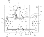
- the refrigerant circuit figure which shows typically the structure of the refrigerant circuit of the air conditioning apparatus which concerns on Embodiment 1 of this invention.
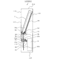
- the front view which shows the external appearance of the indoor unit of the air conditioning apparatus which concerns on Embodiment 1 of this invention.
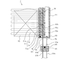
- transmits and shows a part of internal structure of the indoor unit shown in FIG.
- Sectional drawing of planar view which shows an example of the installation form of the temperature sensor in the indoor unit shown in FIG.
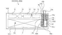
- FIG. 6 is a top view of an indoor unit schematically showing a part of members for explaining an air-conditioning apparatus according to Embodiment 4 of the present invention.
- the side view of the indoor unit which shows typically a part of member explaining the air conditioning apparatus which concerns on Embodiment 4 of this invention, seeing through.
- FIG. 1 is a refrigerant circuit diagram schematically showing a configuration of a refrigerant circuit
- FIG. 2 is an external view of an indoor unit
- FIG. 3 is a front view showing a part of the internal configuration of the indoor unit in a transparent manner
- FIG. 4 is a side view showing a part of the internal configuration of the indoor unit in a transparent manner.
- each figure is shown typically and this invention is not limited to the form shown in figure.
- an air conditioner 100 includes an indoor unit (same as a load side unit) 101 installed indoors, an outdoor unit (same as a heat source side unit) 102 installed outside (not shown), and an indoor unit 101. And an extension pipe 10a, 10b connecting the outdoor unit 102 and the outdoor unit 102. Moreover, the control part 1 is arrange
- the outdoor unit 102 includes a compressor 3 that compresses and discharges the refrigerant, and a refrigerant flow path switching valve (hereinafter, “four-way valve”) that changes the flow direction of the refrigerant in the refrigerant circuit between the cooling operation and the heating operation. 4), an outdoor heat exchanger 5 that is a heat source side heat exchanger that performs heat exchange between the outside air and the refrigerant, an electronically controlled expansion valve that can change the opening degree and depressurize the high-pressure refrigerant to a low pressure, etc.
- a refrigerant flow path switching valve hereinafter, “four-way valve”
- a decompression device (hereinafter referred to as an expansion valve) 6 that is an expansion means is disposed, and these are connected by an outdoor pipe (same as the heat source side refrigerant pipe) 8.
- An outdoor fan 5 f that supplies (blows) outside air to the outdoor heat exchanger 5 is installed to face the outdoor heat exchanger 5. By rotating the outdoor fan 5f, an air flow passing through the outdoor heat exchanger 5 is generated.
- a propeller fan is used as the outdoor air blowing fan 5f, and the outdoor heat exchanger 5 is in the form of sucking outside air through the outdoor heat exchanger 5, and the outdoor heat exchanger 5 is downstream of the air flow generated by the outdoor air blowing fan 5f.
- the outdoor pipe 8 is an outdoor pipe 8a that connects the gas side (cooling operation) extension pipe connection valve 13a and the four-way valve 4, a suction pipe 11 that connects the four-way valve 4 and the compressor 3, and the compressor 3 and four-way valve. 4, the discharge pipe 12 connecting the four-way valve, the outdoor pipe 8c connecting the four-way valve 4 and the outdoor heat exchanger 5, the outdoor pipe 8d connecting the outdoor heat exchanger 5 and the expansion valve 6, the expansion valve 6 and the liquid side (during cooling operation) ) And the outdoor pipe 8b connecting the extension pipe connection valve 13b.
- a gas-side extension pipe connection valve 13a is provided at a connection portion of the outdoor pipe 8 with the gas-side extension pipe 10a, while a liquid-side extension pipe connection is provided at a connection portion with the liquid-side extension pipe 10b.
- a valve 13b is arranged.
- the extension pipe connection valve 13a on the gas side is a two-way valve that can be switched between open and closed, and a flare joint 16a is attached to one end thereof.
- the extension pipe connection valve 13b on the liquid side is a three-way valve that can be switched between open and closed, and is a service port 14b that is used for evacuation (before the refrigerant is supplied to the air conditioner 100).
- a flare joint 16b is attached.
- a range in the outdoor pipe 8 that connects the compressor 3 to the four-way valve 4 inlet on the discharge side of the compressor 3 is referred to as a discharge pipe 12 and is referred to as a suction side of the compressor 3.
- the range connecting the four-way valve 4 to the compressor 3 is referred to as a suction pipe 11.
- the discharge pipe 12 can be used at any time during the cooling operation (operation for supplying the low-temperature and low-pressure refrigerant to the indoor heat exchanger 7) or the heating operation (operation for supplying the high-temperature and high-pressure refrigerant to the indoor heat exchanger 7).
- the low-temperature and low-pressure refrigerant flowing through the suction pipe 11 may be a gas refrigerant or a two-phase state.
- the suction pipe 11 is provided with a service port 14a with a low-pressure side flare joint
- the discharge pipe 12 is provided with a service port 14c with a high-pressure side flare joint.
- a pressure gauge is installed during a trial run at the time of installation or repair. Used to connect and measure operating pressure.
- the flare joints (not shown) of the service ports 14a and 14c are cut off with a male screw. When the outdoor unit 102 is shipped (including when the air conditioner 100 is shipped), the male screw has a flare nut. (Not shown) is attached.
- the indoor unit 101 is provided with an indoor heat exchanger 7 that is a use-side heat exchanger that exchanges heat between indoor air and refrigerant, and indoor pipes (same as use-side refrigerant pipes) 9a and 9b.
- indoor pipes 9a and 9b The configuration of the indoor pipes 9a and 9b will be described in detail separately.
- a flare joint 15a for connecting the gas-side extension pipe 10a is provided at a connection portion between the indoor pipe 9a and the gas-side extension pipe 10a, while the liquid-side extension pipe 10b of the indoor pipe 9b is connected to the gas-side extension pipe 10a.
- the flare joint 15b for connecting the extension pipe 10b on the liquid side is disposed at the connecting portion.
- the flare joints 15a and 15b are cut off with a male screw.
- a female screw that is screwed into the male screw is processed.
- a flare nut (not shown) is attached.
- the indoor air blower fan 7f is installed facing the indoor heat exchanger 7, and the air flow which passes the indoor heat exchanger 7 is produced
- Both ends of the gas side extension pipe 10a are detachably attached to a flare joint 16a attached to the gas side extension pipe connection valve 13a of the outdoor unit 102 and a flare joint 15a attached to the indoor pipe 9a of the indoor unit 101, respectively.
- both ends of the liquid side extension pipe 10b are connected to a flare joint 16b attached to the liquid side extension pipe connection valve 13b of the outdoor unit 102 and a flare joint 15b attached to the indoor pipe 9b of the indoor unit 101.
- the outdoor pipe 8 and the indoor pipes 9a and 9b are connected by the extension pipes 10a and 10b to form a refrigerant circuit, and a compression heat pump cycle in which the refrigerant compressed by the compressor 3 is circulated is configured.
- a solid line arrow indicates the flow direction of the refrigerant during the cooling operation.
- the four-way valve 4 is switched to a refrigerant circuit as indicated by a solid line, and the high-temperature and high-pressure gas refrigerant discharged from the compressor 3 first flows into the outdoor heat exchanger 5 through the four-way valve 4.
- the outdoor heat exchanger 5 acts as a condenser. That is, when the air flow generated by the rotation of the outdoor fan 5f passes through the outdoor heat exchanger 5, the outdoor air passing therethrough exchanges heat with the refrigerant flowing through the outdoor heat exchanger 5, and the heat of condensation of the refrigerant Is added to the outdoor air.
- the refrigerant is condensed in the outdoor heat exchanger 5 to become a liquid refrigerant.
- the liquid refrigerant flows into the expansion valve 6, adiabatically expands in the expansion valve 6, and becomes a low-pressure low-temperature two-phase refrigerant.
- the low-pressure and low-temperature two-phase refrigerant is supplied to the indoor unit 101 via the liquid-side extension pipe 10 b and the indoor pipe 9 b and flows into the indoor heat exchanger 7.
- This indoor heat exchanger 7 acts as an evaporator. That is, when the flow of indoor air generated by the rotation of the indoor blower fan 7f passes through the indoor heat exchanger 7, the indoor air passing therethrough exchanges heat with the refrigerant flowing through the indoor heat exchanger 7, so that the refrigerant becomes room air. It evaporates by taking the heat of evaporation (warm heat) from it, and becomes a low-temperature low-pressure gas refrigerant or two-phase refrigerant state.
- the passing indoor air takes the cold from the refrigerant and is cooled to cool the room.
- the refrigerant that has evaporated in the indoor heat exchanger 7 to become a low-temperature and low-pressure gas refrigerant or a two-phase refrigerant is supplied to the outdoor unit 102 via the gas-side indoor pipe 9a and the extension pipe 10a, and It is sucked into the compressor 3 via the valve 4. Then, it is compressed again into a high-temperature and high-pressure gas refrigerant in the compressor 3. This cycle is repeated in the cooling operation.
- the dotted line arrows indicate the flow direction of the refrigerant during the heating operation. If the four-way valve 4 is switched to a refrigerant circuit as indicated by the dotted line, the refrigerant flows in the opposite direction to that during the cooling operation, and first flows into the indoor heat exchanger 7, and this indoor heat exchanger 7 is connected to the condenser, and The outdoor heat exchanger 5 is caused to act as an evaporator, and the indoor air passing through the indoor heat exchanger 7 is heated by condensing heat (warm heat) to be in a heating operation.
- the refrigerant flowing through the refrigerant circuit has a smaller GWP than the R410A, which is an HFC refrigerant widely used in air conditioners at present, and has a relatively low impact on global warming.
- R32 CH 2 F 2 ; difluoromethane
- Refrigerant is shipped in a state in which a certain amount is enclosed in the outdoor unit 102 in advance, and when the air conditioner 100 is installed, if shortage occurs due to the length of the extension pipes 10a and 10b, additional filling is performed in the field work. Is done. Further, the refrigerant may be shipped without being enclosed in the outdoor unit 102, and the entire amount of the refrigerant may be filled (enclosed) in the field work.
- the refrigerant is not limited to R32, and is a kind of HFC refrigerant as described above, which is slightly flammable like R32, but is a halogenated hydrocarbon having a carbon double bond in the composition.
- HFO refrigerants such as HFO-1234yf (CF 3 CF ⁇ CH 2 ; tetrafluoropropene) and HFO-1234ze (CF 3 —CH ⁇ CHF), which have a smaller GWP than the R32 refrigerant, may be used.
- R290 having a strong retardant may be; (propylene C 3 H 6) HC refrigerant such as (C 3 H 8 propane) and R1270.
- coolant which mixed 2 or more types of these refrigerant
- the indoor unit 101 includes an indoor heat exchanger 7 and an indoor fan that are housed in a housing 110 having a housing front surface 111, a housing top surface 114, a housing back surface 115, and a housing bottom surface 116. 7f (see FIG. 1).
- a suction port 112 is formed in the lower part of the front surface 111 of the casing, and an outlet 113 is formed in the upper part of the front surface 111 of the casing.
- An operation display unit 2 is provided on the front surface 111 of the housing. The operation display unit 2 performs operations such as switching between cooling and heating, switching the air volume of the indoor fan 7f, etc., in addition to operation and stop of the air conditioning apparatus 100, and displays the operation state and the like.
- size and shape of the suction inlet 112 and the blower outlet 113 are not limited to what is illustrated,
- the blower outlet 113 is formed ranging over the housing
- the conditioned air becomes cool air during the cooling operation, warm air during the heating operation, and dry air during the drying operation.
- the inside of the housing 110 is divided into upper and lower parts by a partition plate 20 in which a communication opening 21 is formed, and the lower space is located at a position facing the suction port 112.
- An indoor blower fan 7 f is disposed near the body back surface 115. Further, the indoor heat exchanger 7 is inclined so that the upper end is close to the housing back surface 115 and the lower end is close to the housing front surface 111 in the upper space, and is projected within a range projected vertically below the indoor heat exchanger 7.
- the communication opening 21 of the partition plate 20 is located. That is, the indoor blower fan 7 f sucks indoor air in the lower space from the suction port 112 and supplies the indoor air to the indoor heat exchanger 7 in the upper space via the communication opening 21.
- the indoor air heat-exchanged in the indoor heat exchanger 7 turns into "conditioned air", and it blows off indoors from the blower outlet 113.
- FIG. As described above, the indoor blower fan 7f is driven by a motor (induction motor or DC brushless motor) that is not a brush type, so that there is no spark that may be an ignition source during operation. .
- FIG. 5 explains the air-conditioning apparatus according to Embodiment 1 of the present invention, and is a front view schematically showing an enlarged part of the joining state between the indoor heat exchanger and the indoor piping. .
- the indoor heat exchanger 7 is formed of a plurality of heat radiating plates (same as fins) 70 spaced apart from each other and a plurality of heat transfer tubes 71 penetrating the heat radiating plates 70.
- the heat transfer tube 71 includes a plurality of U-shaped tubes (hereinafter referred to as “hairpins”) 72 having a long straight tube portion, and an arcuate U vent 73 having a short straight tube portion that allows the plurality of hairpins 72 to communicate with each other. It consists of and. At this time, the hairpin 72 and the U vent 73 are connected by a joint portion (hereinafter referred to as a “brazing portion W” and indicated by a black circle in the drawing).
- the number of heat transfer tubes 71 is not limited and may be one or more. Further, the number of hairpins 72 constituting the heat transfer tube 71 is not limited.
- a cylindrical header main pipe 91a is connected to the indoor pipe 9a on the gas side, a plurality of header branch pipes 92a are connected to the header main pipe 91a, and a heat transfer pipe 71 (same as the hairpin 72) is connected to the header branch pipe 92a.
- One end 71a is connected.
- a plurality of indoor refrigerant branch pipes 92b are connected to the liquid (two-phase) side indoor pipe 9b and are branched into a plurality of branches.
- the other end 71b of the heat transfer tube 71 (same as the hairpin 72) is connected to the header branch tube 92a.
- connection between the header main pipe 91a and the header branch pipe 92a, the connection between the header branch pipe 92a and the end 71a, the connection between the indoor pipe 9b and the indoor refrigerant branch pipe 92b, and the indoor refrigerant branch pipe 92b and the end 71b. are connected at a brazing portion W (indicated by black circles in the figure).
- the brazing portion W is shown as the joining portion, but the present invention is not limited to this, and any joining means may be used.
- a first leaked refrigerant receiver 94 is disposed opposite to the header main pipe 91a, etc., parallel to the header main pipe 91a, etc., and vertically below the header main pipe 91a, etc. Attached).
- the first leaked refrigerant receiver 94 is a gutter that covers a vertically lower portion of the position of the brazing part W, and a first leaked refrigerant reservoir 93 is formed at the lower end.
- the first leaked refrigerant receiver 94 is configured to receive the leaked refrigerant and flow it into the first leaked refrigerant reservoir 93 when the refrigerant (having a higher specific gravity than the indoor air) leaks from the position of the brazing part W.
- the shape of the first leakage refrigerant receiver 94 is not limited, and may be a deep shape in which a cutout or a through hole through which the hairpin 72 passes is formed with a rectangular cross section or a circular arc shape. It may be a relatively shallow bottom whose side edge is in contact with or close to the lower surface of 72.
- the first leakage refrigerant reservoir 93 is for temporarily storing the refrigerant flowing along the first leakage refrigerant receiver 94, and the amount of the accumulation is not limited. Therefore, the first leaked refrigerant reservoir portion 93 is regarded as the first leaked refrigerant reservoir portion 93 by closing the lower end of the first leaked refrigerant receiver 94 without providing the first leaked refrigerant reservoir portion 93 specially. Also good. Although the indoor pipe 9a and the indoor pipe 9b penetrate the first leaked refrigerant reservoir 93, the indoor pipe 9a and the indoor pipe 9b are bent to bypass the first leaked refrigerant reservoir 93, and the indoor pipe 9a and the indoor pipe 9b are bypassed. The pipe 9b may be prevented from penetrating the first leaked refrigerant reservoir 93.
- a second leakage refrigerant receiver 95 is disposed vertically below the flare joint 15a and the flare joint 15b.
- the second leaking refrigerant receiver 95 is a box that covers a certain range vertically below the flare joint 15a and the flare joint 15b, and refrigerant (having a higher specific gravity than room air) leaks from the flare joint 15a or the flare joint 15b. In this case, the refrigerant is received and a certain amount is accumulated.
- extension pipe 10a and the extension pipe 10b penetrate the second leaked refrigerant receiver 95, but the extension pipe 10a and the extension pipe 10b are bent to bypass the second leaked refrigerant receiver 95, thereby extending the extension pipe 10a and the extension pipe 10b. May not pass through the second leaked refrigerant receiver 95.
- a temperature sensor On the suction side of the indoor fan 7f (between the suction port 112 and the indoor fan 7f), a temperature sensor (hereinafter referred to as “suction temperature sensor”) that measures the temperature of the intake air (same as indoor air) during operation. S1 is arranged.
- the indoor heat exchanger 7 measures the temperature of the refrigerant flowing into the indoor heat exchanger 7 during the cooling operation, and measures the temperature of the refrigerant flowing out of the indoor heat exchanger 7 during the heating operation.
- Temperature sensor (hereinafter referred to as “liquid pipe sensor”) S2 and a temperature sensor (hereinafter referred to as “two-phase pipe sensor”) that is located at the approximate center of the indoor heat exchanger 7 and measures the evaporation temperature or condensation temperature of the refrigerant. ) S3 is arranged.
- the temperatures detected by the suction temperature sensor S1, the liquid pipe sensor S2, and the two-phase pipe sensor S3 are respectively input to the control unit 1 and used for operation control of the compressor 3 and the like.
- first temperature sensor a temperature sensor (hereinafter referred to as “first temperature sensor”) S4 is installed in the first leaked refrigerant receiver 94 (more precisely, the first leaked refrigerant reservoir 93), and a temperature sensor (hereinafter referred to as “first leaky refrigerant reservoir 93”). S5) (referred to as “second temperature sensor”) is installed. That is, since there is a possibility that the refrigerant leaks from the joint portion by the brazing portion W due to external force such as aging or earthquake, if the refrigerant leaks, the first leaking refrigerant receiver 94 is more than the indoor air The first temperature sensor S4 detects the temperature drop of the atmosphere cooled by heat removal due to the heat of vaporization of the leaked refrigerant.
- the first leakage refrigerant reservoir 93 that accumulates a certain amount is provided and the first temperature sensor S4 is provided here, the temperature drop of the ambient temperature (ambient air) due to the heat of vaporization of the leakage refrigerant can be accelerated. It is possible to detect the refrigerant leakage early and reliably.
- the first leakage refrigerant receiver 94 may be omitted and only the first temperature sensor S4 may be installed on the upper side of the partition plate 20.
- the first temperature sensor S4 is installed at a position close to the divider plate 20 in order to stop on the divider plate 20. By doing so, it is possible to detect the temperature drop of the surrounding air due to the heat of vaporization of the refrigerant leakage.
- coolant may also leak by the external force of aged deterioration, an earthquake, etc. also in the junction part by the flare joints 15a and 15b, the refrigerant
- the second leaked refrigerant receiver 95 that receives and accumulates the second temperature sensor S5
- the refrigerant leaking from the flare joint 15a or the flare joint 15b (having a higher specific gravity than room air) descends and stays on the casing bottom surface 116 of the casing 110, a second leaking refrigerant receiver 95 is provided.
- the second temperature sensor S5 may be installed at a position close to the housing bottom surface 116. Furthermore, since the refrigerant leaking from the flare joint 15a or the flare joint 15b (having a higher specific gravity than the indoor air) is vaporized, the temperature of the air in the lower range from the partition plate 20 of the housing 110 is lowered. The two-leakage refrigerant receiver 95 and the second temperature sensor S5 are removed, and the temperature detection by the suction temperature sensor S1 is performed during operation and during operation stop so that the function of the second temperature sensor S5 is added to the suction temperature sensor S1. (It is the same as adding the function of the suction temperature sensor S1 to the second temperature sensor S5).
- FIG. 6A and 6B illustrate the air-conditioning apparatus according to Embodiment 1 of the present invention, and show an example of an installation form of a temperature sensor.
- FIG. 6A is a sectional view in plan view
- FIG. 6B is a front view.
- 1st temperature sensor S4 is installed in the indoor piping 9b through the holder 80 inferior in heat conductivity. That is, the holder 80 includes a pipe gripping portion 81 having a C-shaped cross section for gripping the indoor pipe 9b, a sensor gripping portion 83 having a C-shaped cross section for gripping the first temperature sensor S4, a pipe gripping portion 81, and a sensor gripping portion.
- the holder 80 is made of a material having a low heat transfer coefficient, for example, a synthetic resin, and the cross-sectional area of the arm portion 82 is small.
- the first leaking refrigerant pool having a U-shaped cross section or the first leaked refrigerant pool part 93 having a planar or curved shape is used. It may be installed in the section 93.
- the liquid pipe sensor S2 is directly installed on the outer surface of the indoor pipe 9b, and directly detects the outer surface temperature of the indoor pipe 9b.
- control unit 1 controls the refrigeration cycle (the compressor 3, the expansion valve 6 and the like) based on the values detected by the suction temperature sensor S1, the liquid pipe sensor S2, and the two-phase pipe sensor S3.
- the positions where the liquid pipe sensor S2 and the two-phase pipe sensor S3 are installed are not limited to the illustrated positions.
- FIG. 7 is a flowchart illustrating a refrigerant leak detection method according to Embodiment 2 of the present invention.
- the refrigerant leakage detection method is a method of detecting refrigerant leakage in the air conditioner 100 (Embodiment 1).
- symbol is attached
- the first temperature sensor S4 and the second temperature sensor S5 detect the temperature only when the operation is stopped (while the indoor fan 7f does not rotate) (Step 1).
- the first temperature sensor S4 and the second temperature sensor S5 detect the temperature at a constant time interval, and the detected amount of change in the temperature of either the first temperature sensor S4 or the second temperature sensor S5 is a constant threshold (for example When the difference between the previous detection value and the current detection value is 5 ° C.) or when the degree of change in the detected temperature falls below a certain threshold (for example, 5 ° C./min), the control unit 1 sets the refrigerant Is determined to be leaking (Step 3).
- Step 4 the control unit 1 of the air conditioner 100 determines that the refrigerant is leaking during the operation stop.
- the control unit 1 starts the rotation of the indoor blower fan 7f to stir the indoor air (Step 4).
- notification means operation display unit 2 or sound generation means not shown
- Step 5 execution of Step 5 may be omitted.
- FIG. 8 is an experimental result showing temperature detection characteristics for explaining the refrigerant leakage detection method according to Embodiment 2 of the present invention. That is, FIG. 8 shows the temperature (° C.) detected by the second temperature sensor S5 and the suction temperature sensor S1 when the refrigerant R32 is leaked from the flare joint 15a at a leak rate of 150 g / min.
- the vertical axis shows the time (minutes) from the start of leakage on the horizontal axis. That is, the refrigerant leaking from the flare joint 15a rapidly adiabatically expands and takes away heat from the surroundings, and has a specific gravity heavier than that of the room air, so it descends and flows into the second leaking refrigerant receiver 95.
- the ambient temperature particularly the ambient temperature of the second leaked refrigerant receiver 95
- the temperature detected by the second temperature sensor S5 immediately decreases immediately after the start of leakage.
- the temperature detected by the suction temperature sensor S1 is not as high as the second temperature sensor S5
- the refrigerant leakage detection method in the air conditioner 100 has the following significant operational effects.
- the detection sensitivity may become slow due to the heat capacity (thermal inertia) of a member such as a pipe. Absent.
- the leaked refrigerant (which may include air cooled by heat removal due to adiabatic expansion of the leaked refrigerant) is more reliable. In addition, it reaches around the first temperature sensor S4 and the second temperature sensor S5.
- the first leaked refrigerant receiver 94 and the second leaked refrigerant receiver 95 are provided, and the first temperature sensor S4 and the second temperature sensor S5 are provided respectively.
- the present invention is not limited to this.
- the first temperature sensor S4 may be omitted by forming an opening communicating with the second leaked refrigerant receiver 95 in both the first leaked refrigerant receiver 94 and the partition plate 20. At this time, if the upper edge of the second leaked refrigerant receiver 95 is in contact with or close to the partition plate 20, the flow of the leaked refrigerant around the second temperature sensor S5 is further promoted.
- FIG. 9 is a side view of the indoor unit for explaining the air-conditioning apparatus according to Embodiment 3 of the present invention and schematically showing a part of the members transparently.
- symbol is attached
- the third leaking refrigerant receiver 96 of the indoor unit 201 included in the air conditioning apparatus 200 has a funnel shape and an inverted truncated cone shape with a bottom removed.
- the suction temperature sensor S1 is disposed below the third leaked refrigerant receiver 96, and the second temperature sensor S5 is not provided in the third leaked refrigerant receiver 96 as in the first embodiment. Except this point, the air conditioner 200 is the same as the air conditioner 100 (Embodiment 1).
- the refrigerant leak detection method in the air conditioning apparatus 200 is in accordance with the second embodiment, and the second temperature sensor S5 in the second embodiment is read as the suction temperature sensor S1. Therefore, since the number of parts is reduced by the amount that the second temperature sensor S5 is not provided, the manufacturing cost of the air conditioning apparatus 200 is low.
- the 1st temperature sensor S4 is installed in the 1st leaking refrigerant receiver 94 above, this invention is not limited to this, For example, both the 1st leaking refrigerant receiver 94 and the partition plate 20 are used.
- the opening of the first temperature sensor S4 may be omitted by forming an opening communicating with the third leaking refrigerant receiver 96 (at this time, the upper edge of the third leaking refrigerant receiver 96 abuts against the partition plate 20). Or if they are close, the flow of the leaked refrigerant around the suction temperature sensor S1 is further promoted).
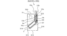
- FIG. 10A and 10B illustrate an air-conditioning apparatus according to Embodiment 4 of the present invention.
- FIG. 10A is a top view of an indoor unit schematically showing a part of the members
- FIG. 10B [FIG. 4] is a side view of an indoor unit schematically showing a part of members through.
- symbol is attached
- the indoor unit 301 of the air conditioner 300 is a ceiling type installed in a suspended state from the ceiling (not shown) of the room, and includes the indoor heat exchanger 7 and the indoor air blower inside.
- a housing 310 is provided for housing the fan 7f.
- a suction port 312 is formed near the housing rear surface 315 of the housing bottom surface 316 of the housing 310, and an air outlet 313 is provided on the housing front surface 311.
- the indoor blower fan 7f is disposed at a position near the housing back surface 315, and the indoor heat exchanger 7 is disposed in an inclined state toward the corners of the housing front surface 311 and the housing top surface 314.
- indoor piping 9a, 9b is connected to the indoor heat exchanger 7 at a position near the housing right end surface 318. Since the form of this connection is the same as that of the first embodiment (the brazing portion W, see FIG. 5), the description thereof is omitted. Moreover, the 4th leaking refrigerant
- a receiver 97 is provided (imaginary lines obtained by projecting the positions of all brazing portions W and the positions of the flare joints 15a and 15b vertically downward intersect the fourth leaked refrigerant receiver 97).
- the fourth leaking refrigerant receiver 97 has a U-shaped cross section (including one whose opening side is wider than the bottom side) or a circular arc shape, and is an eaves having an open upper end and closed at the lower end. Furthermore, a temperature sensor (hereinafter referred to as “third temperature sensor”) S6 is installed at a position near the lower end of the fourth leaked refrigerant receiver 97.
- the refrigerant leak detection method in the air conditioning apparatus 300 is based on Embodiment 2, Comprising: 1st temperature sensor S4 and 2nd temperature sensor S5 in Embodiment 2 are read as 3rd temperature sensor S6. Therefore, similar to the first and second embodiments, it is possible to detect at an early stage that the refrigerant has leaked.
- connection part (brazing part W) of indoor heat exchanger 7 and indoor piping 9a, 9b and the position of flare joints 15a, 15b are separated (when separated in the horizontal direction), respectively.
- a leakage refrigerant receiver and a temperature sensor may be installed at the position.
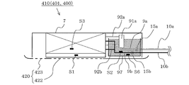
- FIG. 11A and 11B illustrate an air-conditioning apparatus according to Embodiment 5 of the present invention.
- FIG. 11A is a bottom view in plan view
- FIG. 11B is a cross-sectional view in side view.
- symbol is attached
- the indoor unit 401 of the air conditioner 400 is a ceiling cassette type installed in a state of being embedded in the ceiling (not shown) of the room, and includes the indoor heat exchanger 7 and the indoor air blower inside.
- a housing 410 is provided for housing the fan 7f.
- the casing 410 is a box having a square section with chamfered corners, and a decorative grill 420 is detachably installed on the open bottom 416 of the casing.
- the decorative grill 420 has a suction port 422 formed at the center, and has four outlets 423 formed around the suction port 422.
- the indoor air blower fan 7f is installed in the center of the housing
- the indoor air sucked in by 7f is heat-exchanged in the indoor heat exchanger 7, and blown out from the outside of the indoor heat exchanger 7 into the room (not shown) via the blowout port 423.
- Flare joints 15a and 15b are arranged at one of the four corners of the housing 410, and the indoor heat exchanger 7 and the indoor pipes 9a and 9b are connected at the corner. Since the form of this connection is the same as that of the first embodiment (the brazing portion W, see FIG. 5), the description thereof is omitted. Then, as in the fourth embodiment, the position below the connection portion (the brazing portion W, see FIG. 5) between the indoor heat exchanger 7 and the indoor pipes 9a and 9b, and the vertically below the flare joints 15a and 15b.
- the fourth leaked refrigerant receiver 97 is provided (the imaginary line obtained by projecting the positions of all brazing portions W and the positions of the flare joints 15a and 15b vertically downwards intersects the fourth leaked refrigerant receiver 97). ).
- the fourth leaking refrigerant receiver 97 is a box having an open top surface and has a bottom surface parallel to the casing top surface 414, and a third temperature sensor S 6 is installed near the bottom surface in the fourth leaking refrigerant receiver 97. ing. Therefore, the air conditioning apparatus 400 has the same effects as the air conditioning apparatus 100 (Embodiment 1 and Embodiment 2), as with the air conditioning apparatus 200 (Embodiment 3).
- the floor-standing type (Embodiments 1 and 3), the ceiling-suspended type (Embodiment 4), and the ceiling cassette type (Embodiment 5) have been described as executing the second embodiment.
- the second embodiment can be executed, and the same effects can be obtained.
- the air conditioners 100 to 400 have been described above, the present invention is not limited to this, and may be a refrigeration cycle apparatus including a hot water heater or the like, for example.
Landscapes
- Engineering & Computer Science (AREA)
- Mechanical Engineering (AREA)
- General Engineering & Computer Science (AREA)
- Chemical & Material Sciences (AREA)
- Combustion & Propulsion (AREA)
- Physics & Mathematics (AREA)
- Thermal Sciences (AREA)
- Air Conditioning Control Device (AREA)
Abstract
Priority Applications (6)
| Application Number | Priority Date | Filing Date | Title |
|---|---|---|---|
| MX2016002486A MX2016002486A (es) | 2013-08-26 | 2014-07-29 | Aparato de aire acondicionado y metodo de deteccion de fuga de refrigerante. |
| EP14840930.3A EP3040654B1 (fr) | 2013-08-26 | 2014-07-29 | Dispositif de climatisation et procédé de détection de fuite de fluide frigorigène |
| US14/891,975 US10539358B2 (en) | 2013-08-26 | 2014-07-29 | Air-conditioning apparatus and refrigerant leakage detection method |
| AU2014313328A AU2014313328B2 (en) | 2013-08-26 | 2014-07-29 | Air-conditioning apparatus and refrigerant leakage detection method |
| CN201420484518.2U CN204100499U (zh) | 2013-08-26 | 2014-08-26 | 空调装置 |
| CN201410424347.9A CN104422087A (zh) | 2013-08-26 | 2014-08-26 | 空调装置以及制冷剂泄漏检测方法 |
Applications Claiming Priority (2)
| Application Number | Priority Date | Filing Date | Title |
|---|---|---|---|
| JP2013-174790 | 2013-08-26 | ||
| JP2013174790A JP5818849B2 (ja) | 2013-08-26 | 2013-08-26 | 空気調和装置および冷媒漏洩検知方法 |
Publications (1)
| Publication Number | Publication Date |
|---|---|
| WO2015029678A1 true WO2015029678A1 (fr) | 2015-03-05 |
Family
ID=52586252
Family Applications (1)
| Application Number | Title | Priority Date | Filing Date |
|---|---|---|---|
| PCT/JP2014/069972 WO2015029678A1 (fr) | 2013-08-26 | 2014-07-29 | Dispositif de climatisation et procédé de détection de fuite de fluide frigorigène |
Country Status (7)
| Country | Link |
|---|---|
| US (1) | US10539358B2 (fr) |
| EP (1) | EP3040654B1 (fr) |
| JP (1) | JP5818849B2 (fr) |
| CN (1) | CN104422087A (fr) |
| AU (1) | AU2014313328B2 (fr) |
| MX (1) | MX2016002486A (fr) |
| WO (1) | WO2015029678A1 (fr) |
Cited By (7)
| Publication number | Priority date | Publication date | Assignee | Title |
|---|---|---|---|---|
| US20160123645A1 (en) * | 2014-10-29 | 2016-05-05 | Lg Electronics Inc. | Air conditioner and method of controlling the same |
| WO2016153021A1 (fr) * | 2015-03-26 | 2016-09-29 | 三菱電機株式会社 | Unité intérieure de climatiseur |
| WO2017013715A1 (fr) * | 2015-07-17 | 2017-01-26 | 三菱電機株式会社 | Unité intérieure pour climatiseur et climatiseur comprenant l'unité intérieure |
| WO2018216052A1 (fr) * | 2017-05-22 | 2018-11-29 | 三菱電機株式会社 | Dispositif unitaire pour dispositif à cycle frigorifique |
| EP3396277A4 (fr) * | 2015-12-21 | 2018-12-12 | Mitsubishi Electric Corporation | Dispositif à cycle de réfrigération |
| EP3517857A1 (fr) * | 2015-04-03 | 2019-07-31 | Mitsubishi Electric Corporation | Dispositif à cycle de réfrigération et système à cycle de réfrigération |
| JP2020134033A (ja) * | 2019-02-20 | 2020-08-31 | パナソニックIpマネジメント株式会社 | 室内ユニット |
Families Citing this family (26)
| Publication number | Priority date | Publication date | Assignee | Title |
|---|---|---|---|---|
| JP5892199B2 (ja) * | 2014-06-27 | 2016-03-23 | ダイキン工業株式会社 | 空調室内機 |
| US10408484B2 (en) * | 2015-03-31 | 2019-09-10 | Daikin Industries, Ltd. | Air-conditioning apparatus with a refrigerant leak sensor in an indoor unit |
| JP6135705B2 (ja) * | 2015-04-06 | 2017-05-31 | ダイキン工業株式会社 | 利用側空調装置 |
| CN104949266B (zh) * | 2015-06-04 | 2017-11-10 | 广东美的制冷设备有限公司 | 空调器和空调器的冷媒泄露检测方法 |
| JP2017040381A (ja) * | 2015-08-17 | 2017-02-23 | ダイキン工業株式会社 | 空調室内機 |
| WO2017081735A1 (fr) * | 2015-11-09 | 2017-05-18 | 三菱電機株式会社 | Dispositif de cycle frigorifique et procédé de détection de fuite de fluide frigorigène |
| CN105485856B (zh) * | 2015-12-31 | 2019-04-02 | 广东美的制冷设备有限公司 | 空调系统及空调系统制热状态下的异常检测方法 |
| EP3441689B1 (fr) * | 2016-04-05 | 2020-12-23 | Mitsubishi Electric Corporation | Climatiseur |
| WO2017195336A1 (fr) * | 2016-05-12 | 2017-11-16 | 三菱電機株式会社 | Mécanisme de détection de fuite de fluide frigorigène |
| WO2017199342A1 (fr) * | 2016-05-17 | 2017-11-23 | 三菱電機株式会社 | Dispositif à cycle frigorifique |
| JP6827279B2 (ja) | 2016-07-15 | 2021-02-10 | 日立ジョンソンコントロールズ空調株式会社 | 冷暖切替ユニット及びそれを備える空気調和機 |
| US10859299B2 (en) * | 2016-11-16 | 2020-12-08 | Mitsubishi Electric Corporation | Air-conditioning apparatus and refrigerant leakage detection method |
| CN106840524A (zh) * | 2016-12-29 | 2017-06-13 | 大连葆光节能空调设备厂 | 一种溴化锂热泵机房漏水监控系统 |
| JP6555293B2 (ja) * | 2017-03-31 | 2019-08-07 | ダイキン工業株式会社 | 冷凍装置の室内ユニット |
| EP3607250B1 (fr) * | 2017-04-06 | 2024-03-27 | Carrier Corporation | Détection de fuite de fluide frigorigène à valeur de potentiel de réchauffement global modéré à faible |
| ES2899040T3 (es) * | 2017-08-10 | 2022-03-09 | Mitsubishi Electric Corp | Dispositivo de ciclo de refrigeración |
| CN107289599B (zh) * | 2017-08-10 | 2020-03-17 | 四川长虹电器股份有限公司 | 一种检测空调冷媒泄露量的装置和方法 |
| KR102323029B1 (ko) * | 2017-08-18 | 2021-11-05 | 주식회사 엘지에너지솔루션 | 자이로센서 및 수분감지센서를 이용한 배터리팩 내 누액 감지 장치 및 감지 방법 |
| EP3505842B1 (fr) * | 2017-12-26 | 2023-01-25 | Trane International Inc. | Modification de produits cvc r-410a pour gérer les réfrigérants inflammables |
| US11473831B2 (en) * | 2018-01-12 | 2022-10-18 | Mitsubishi Electric Corporation | Air-conditioning apparatus |
| CN108760161B (zh) * | 2018-05-17 | 2023-08-18 | 南京百灵汽车电气机械有限公司 | 一种蒸发器模拟实用检测壳体 |
| CN110736183B (zh) * | 2018-07-18 | 2021-04-27 | 奥克斯空调股份有限公司 | 一种空调冷媒泄露的检测方法及装置 |
| CN110940051B (zh) * | 2018-09-25 | 2021-03-12 | 奥克斯空调股份有限公司 | 一种空调冷媒泄漏检测方法及使用该方法的空调 |
| WO2020144769A1 (fr) * | 2019-01-09 | 2020-07-16 | 三菱電機株式会社 | Appareil de climatisation |
| US11231198B2 (en) | 2019-09-05 | 2022-01-25 | Trane International Inc. | Systems and methods for refrigerant leak detection in a climate control system |
| US11585575B2 (en) | 2020-07-08 | 2023-02-21 | Rheem Manufacturing Company | Dual-circuit heating, ventilation, air conditioning, and refrigeration systems and associated methods |
Citations (10)
| Publication number | Priority date | Publication date | Assignee | Title |
|---|---|---|---|---|
| JPH04369370A (ja) * | 1991-06-14 | 1992-12-22 | Hitachi Ltd | 冷凍装置 |
| JPH11142004A (ja) * | 1997-11-05 | 1999-05-28 | Daikin Ind Ltd | 冷凍装置 |
| JP2000081258A (ja) | 1998-07-01 | 2000-03-21 | Daikin Ind Ltd | 冷凍装置および冷媒漏洩検出方法 |
| JP2000146393A (ja) * | 1998-11-05 | 2000-05-26 | Hitachi Ltd | 冷凍装置 |
| JP2000258000A (ja) * | 1999-03-02 | 2000-09-22 | Daikin Ind Ltd | 空気調和装置 |
| JP2002103952A (ja) * | 2000-10-03 | 2002-04-09 | Denso Corp | 車両用空調制御装置 |
| JP2002228281A (ja) * | 2001-01-31 | 2002-08-14 | Sanyo Electric Co Ltd | 空気調和機 |
| JP2004286255A (ja) * | 2003-03-19 | 2004-10-14 | Gac Corp | 制御盤用空気調和装置 |
| JP2010078285A (ja) * | 2008-09-29 | 2010-04-08 | Mitsubishi Electric Corp | ヒートポンプ給湯機 |
| JP2013113555A (ja) * | 2011-11-30 | 2013-06-10 | Mitsubishi Heavy Ind Ltd | ターボ冷凍機 |
Family Cites Families (28)
| Publication number | Priority date | Publication date | Assignee | Title |
|---|---|---|---|---|
| US4856288A (en) * | 1983-07-18 | 1989-08-15 | Weber Robert C | Refrigerant alert and automatic recharging device |
| US4745765A (en) * | 1987-05-11 | 1988-05-24 | General Motors Corporation | Low refrigerant charge detecting device |
| US4843835A (en) * | 1988-09-27 | 1989-07-04 | Amana Refrigeration, Inc. | Refrigerator drain funnel |
| US5152152A (en) * | 1992-02-10 | 1992-10-06 | Thermo King Corporation | Method of determining refrigerant charge |
| JPH10122711A (ja) * | 1996-10-18 | 1998-05-15 | Matsushita Electric Ind Co Ltd | 冷凍サイクル制御装置 |
| US6330802B1 (en) * | 2000-02-22 | 2001-12-18 | Behr Climate Systems, Inc. | Refrigerant loss detection |
| JP4588233B2 (ja) * | 2000-07-25 | 2010-11-24 | 富士フイルム株式会社 | 製膜設備 |
| CN1161570C (zh) * | 2000-09-26 | 2004-08-11 | 大金工业株式会社 | 空调机 |
| WO2003027587A1 (fr) * | 2001-09-19 | 2003-04-03 | Kabushiki Kaisha Toshiba | Refrigerateur-congelateur, controleur pour refrigerateur-congelateur, et procede de determination de fuite de refrigerant |
| CN2502190Y (zh) * | 2001-10-13 | 2002-07-24 | 中国科学技术大学 | 四季节能冷暖空调热水装置 |
| JP3999961B2 (ja) * | 2001-11-01 | 2007-10-31 | 株式会社東芝 | 冷蔵庫 |
| US6772519B2 (en) * | 2002-10-28 | 2004-08-10 | Ico | Flexible hose system for installing residential and commercial facility air conditioning system |
| CN1755341A (zh) * | 2004-09-29 | 2006-04-05 | 乐金电子(天津)电器有限公司 | 空调器的冷媒泄漏检测装置及其方法 |
| JP3786133B1 (ja) | 2005-03-03 | 2006-06-14 | ダイキン工業株式会社 | 空気調和装置 |
| GB2428896A (en) * | 2005-07-26 | 2007-02-07 | Trox | Detecting a leak in a cooling system |
| US7597137B2 (en) * | 2007-02-28 | 2009-10-06 | Colmac Coil Manufacturing, Inc. | Heat exchanger system |
| JP5186951B2 (ja) * | 2008-02-29 | 2013-04-24 | ダイキン工業株式会社 | 空気調和装置 |
| JP5040975B2 (ja) * | 2008-09-30 | 2012-10-03 | ダイキン工業株式会社 | 漏洩診断装置 |
| KR20100056204A (ko) * | 2008-11-19 | 2010-05-27 | 삼성전자주식회사 | 멀티형 공기조화기 및 그 냉매 누설 진단방법 |
| WO2010062923A1 (fr) * | 2008-11-26 | 2010-06-03 | Delphi Technologies, Inc. | Système de détection de fuite de réfrigérant |
| US20110112814A1 (en) * | 2009-11-11 | 2011-05-12 | Emerson Retail Services, Inc. | Refrigerant leak detection system and method |
| WO2011099063A1 (fr) * | 2010-02-10 | 2011-08-18 | 三菱電機株式会社 | Dispositif de climatisation |
| WO2011135946A1 (fr) * | 2010-04-28 | 2011-11-03 | ダイキン工業株式会社 | Dispositif échangeur de chaleur et tube de raccordement utilisé dans celui-ci |
| JP5838660B2 (ja) * | 2011-08-29 | 2016-01-06 | 株式会社ノーリツ | ヒートポンプ給湯装置 |
| US8931509B2 (en) * | 2011-10-07 | 2015-01-13 | Trane International Inc. | Pressure correcting distributor for heating and cooling systems |
| WO2013106725A1 (fr) * | 2012-01-13 | 2013-07-18 | Manitowoc Foodservice Companies, Llc | Condenseur à faible volume de fluide frigorigène pour fluide frigorigène à hydrocarbures et machine de fabrication de glace utilisant celui-ci |
| DK2812640T3 (en) * | 2012-02-10 | 2018-11-26 | Carrier Corp | PROCEDURE FOR DETECTING LOSS OF REFRIGERANT |
| CN204100499U (zh) | 2013-08-26 | 2015-01-14 | 三菱电机株式会社 | 空调装置 |
-
2013
- 2013-08-26 JP JP2013174790A patent/JP5818849B2/ja active Active
-
2014
- 2014-07-29 WO PCT/JP2014/069972 patent/WO2015029678A1/fr active Application Filing
- 2014-07-29 AU AU2014313328A patent/AU2014313328B2/en active Active
- 2014-07-29 EP EP14840930.3A patent/EP3040654B1/fr active Active
- 2014-07-29 US US14/891,975 patent/US10539358B2/en active Active
- 2014-07-29 MX MX2016002486A patent/MX2016002486A/es active IP Right Grant
- 2014-08-26 CN CN201410424347.9A patent/CN104422087A/zh active Pending
Patent Citations (10)
| Publication number | Priority date | Publication date | Assignee | Title |
|---|---|---|---|---|
| JPH04369370A (ja) * | 1991-06-14 | 1992-12-22 | Hitachi Ltd | 冷凍装置 |
| JPH11142004A (ja) * | 1997-11-05 | 1999-05-28 | Daikin Ind Ltd | 冷凍装置 |
| JP2000081258A (ja) | 1998-07-01 | 2000-03-21 | Daikin Ind Ltd | 冷凍装置および冷媒漏洩検出方法 |
| JP2000146393A (ja) * | 1998-11-05 | 2000-05-26 | Hitachi Ltd | 冷凍装置 |
| JP2000258000A (ja) * | 1999-03-02 | 2000-09-22 | Daikin Ind Ltd | 空気調和装置 |
| JP2002103952A (ja) * | 2000-10-03 | 2002-04-09 | Denso Corp | 車両用空調制御装置 |
| JP2002228281A (ja) * | 2001-01-31 | 2002-08-14 | Sanyo Electric Co Ltd | 空気調和機 |
| JP2004286255A (ja) * | 2003-03-19 | 2004-10-14 | Gac Corp | 制御盤用空気調和装置 |
| JP2010078285A (ja) * | 2008-09-29 | 2010-04-08 | Mitsubishi Electric Corp | ヒートポンプ給湯機 |
| JP2013113555A (ja) * | 2011-11-30 | 2013-06-10 | Mitsubishi Heavy Ind Ltd | ターボ冷凍機 |
Non-Patent Citations (1)
| Title |
|---|
| See also references of EP3040654A4 |
Cited By (13)
| Publication number | Priority date | Publication date | Assignee | Title |
|---|---|---|---|---|
| US20160123645A1 (en) * | 2014-10-29 | 2016-05-05 | Lg Electronics Inc. | Air conditioner and method of controlling the same |
| EP3276284A4 (fr) * | 2015-03-26 | 2018-06-20 | Mitsubishi Electric Corporation | Unité intérieure de climatiseur |
| WO2016153021A1 (fr) * | 2015-03-26 | 2016-09-29 | 三菱電機株式会社 | Unité intérieure de climatiseur |
| WO2016151641A1 (fr) * | 2015-03-26 | 2016-09-29 | 三菱電機株式会社 | Unité intérieure de climatiseur |
| JPWO2016153021A1 (ja) * | 2015-03-26 | 2017-06-22 | 三菱電機株式会社 | 空気調和機の室内機 |
| EP3517857A1 (fr) * | 2015-04-03 | 2019-07-31 | Mitsubishi Electric Corporation | Dispositif à cycle de réfrigération et système à cycle de réfrigération |
| WO2017013715A1 (fr) * | 2015-07-17 | 2017-01-26 | 三菱電機株式会社 | Unité intérieure pour climatiseur et climatiseur comprenant l'unité intérieure |
| EP3150943B1 (fr) * | 2015-07-17 | 2019-03-27 | Mitsubishi Electric Corporation | Climatiseur comprenant une unité intérieure et une unité extérieure |
| JPWO2017013715A1 (ja) * | 2015-07-17 | 2018-02-01 | 三菱電機株式会社 | 空気調和装置 |
| EP3396277A4 (fr) * | 2015-12-21 | 2018-12-12 | Mitsubishi Electric Corporation | Dispositif à cycle de réfrigération |
| WO2018216052A1 (fr) * | 2017-05-22 | 2018-11-29 | 三菱電機株式会社 | Dispositif unitaire pour dispositif à cycle frigorifique |
| JPWO2018216052A1 (ja) * | 2017-05-22 | 2019-12-19 | 三菱電機株式会社 | 冷凍サイクル装置のユニット装置 |
| JP2020134033A (ja) * | 2019-02-20 | 2020-08-31 | パナソニックIpマネジメント株式会社 | 室内ユニット |
Also Published As
| Publication number | Publication date |
|---|---|
| CN104422087A (zh) | 2015-03-18 |
| EP3040654B1 (fr) | 2021-06-02 |
| US20160091241A1 (en) | 2016-03-31 |
| MX2016002486A (es) | 2016-05-31 |
| EP3040654A1 (fr) | 2016-07-06 |
| AU2014313328A1 (en) | 2016-02-04 |
| JP2015042930A (ja) | 2015-03-05 |
| US10539358B2 (en) | 2020-01-21 |
| EP3040654A4 (fr) | 2017-03-29 |
| AU2014313328B2 (en) | 2017-03-09 |
| JP5818849B2 (ja) | 2015-11-18 |
Similar Documents
| Publication | Publication Date | Title |
|---|---|---|
| JP5818849B2 (ja) | 空気調和装置および冷媒漏洩検知方法 | |
| JP6779355B2 (ja) | 空気調和装置の冷媒量設定方法 | |
| JP5665937B1 (ja) | 冷凍サイクル装置 | |
| JP6099608B2 (ja) | ヒートポンプ装置 | |
| US10724766B2 (en) | Refrigeration cycle apparatus | |
| CN110226071B (zh) | 空调装置 | |
| CN108351139B (zh) | 冷冻循环装置以及制冷剂泄漏检测方法 | |
| US10859299B2 (en) | Air-conditioning apparatus and refrigerant leakage detection method | |
| JP6223324B2 (ja) | 冷媒漏洩検知装置及び冷凍サイクル装置 | |
| JP6272149B2 (ja) | 空気調和装置 |
Legal Events
| Date | Code | Title | Description |
|---|---|---|---|
| 121 | Ep: the epo has been informed by wipo that ep was designated in this application |
Ref document number: 14840930 Country of ref document: EP Kind code of ref document: A1 |
|
| WWE | Wipo information: entry into national phase |
Ref document number: 14891975 Country of ref document: US |
|
| REEP | Request for entry into the european phase |
Ref document number: 2014840930 Country of ref document: EP |
|
| WWE | Wipo information: entry into national phase |
Ref document number: 2014840930 Country of ref document: EP |
|
| ENP | Entry into the national phase |
Ref document number: 2014313328 Country of ref document: AU Date of ref document: 20140729 Kind code of ref document: A |
|
| WWE | Wipo information: entry into national phase |
Ref document number: MX/A/2016/002486 Country of ref document: MX |
|
| NENP | Non-entry into the national phase |
Ref country code: DE |