WO2015029663A1 - シリンダヘッドボルトの締結構造 - Google Patents
シリンダヘッドボルトの締結構造 Download PDFInfo
- Publication number
- WO2015029663A1 WO2015029663A1 PCT/JP2014/069719 JP2014069719W WO2015029663A1 WO 2015029663 A1 WO2015029663 A1 WO 2015029663A1 JP 2014069719 W JP2014069719 W JP 2014069719W WO 2015029663 A1 WO2015029663 A1 WO 2015029663A1
- Authority
- WO
- WIPO (PCT)
- Prior art keywords
- cylinder head
- head bolt
- bolt
- fastening structure
- flat washer
- Prior art date
Links
- 239000000463 material Substances 0.000 claims description 7
- RYGMFSIKBFXOCR-UHFFFAOYSA-N Copper Chemical compound [Cu] RYGMFSIKBFXOCR-UHFFFAOYSA-N 0.000 claims description 6
- 229910052802 copper Inorganic materials 0.000 claims description 6
- 239000010949 copper Substances 0.000 claims description 6
- 238000007747 plating Methods 0.000 claims description 5
- CWYNVVGOOAEACU-UHFFFAOYSA-N Fe2+ Chemical compound [Fe+2] CWYNVVGOOAEACU-UHFFFAOYSA-N 0.000 claims 1
- XEEYBQQBJWHFJM-UHFFFAOYSA-N Iron Chemical compound [Fe] XEEYBQQBJWHFJM-UHFFFAOYSA-N 0.000 description 6
- 238000003780 insertion Methods 0.000 description 6
- 230000037431 insertion Effects 0.000 description 6
- 229910052742 iron Inorganic materials 0.000 description 3
- 230000003746 surface roughness Effects 0.000 description 3
- 230000000694 effects Effects 0.000 description 2
- 238000000034 method Methods 0.000 description 2
- 238000012986 modification Methods 0.000 description 2
- 230000004048 modification Effects 0.000 description 2
- 238000007792 addition Methods 0.000 description 1
- XAGFODPZIPBFFR-UHFFFAOYSA-N aluminium Chemical compound [Al] XAGFODPZIPBFFR-UHFFFAOYSA-N 0.000 description 1
- 229910052782 aluminium Inorganic materials 0.000 description 1
- 238000012217 deletion Methods 0.000 description 1
- 230000037430 deletion Effects 0.000 description 1
- 238000010586 diagram Methods 0.000 description 1
- 239000006185 dispersion Substances 0.000 description 1
- 238000002474 experimental method Methods 0.000 description 1
- 230000002093 peripheral effect Effects 0.000 description 1
- 230000003068 static effect Effects 0.000 description 1
Images


Classifications
-
- F—MECHANICAL ENGINEERING; LIGHTING; HEATING; WEAPONS; BLASTING
- F02—COMBUSTION ENGINES; HOT-GAS OR COMBUSTION-PRODUCT ENGINE PLANTS
- F02F—CYLINDERS, PISTONS OR CASINGS, FOR COMBUSTION ENGINES; ARRANGEMENTS OF SEALINGS IN COMBUSTION ENGINES
- F02F1/00—Cylinders; Cylinder heads
- F02F1/24—Cylinder heads
-
- F—MECHANICAL ENGINEERING; LIGHTING; HEATING; WEAPONS; BLASTING
- F16—ENGINEERING ELEMENTS AND UNITS; GENERAL MEASURES FOR PRODUCING AND MAINTAINING EFFECTIVE FUNCTIONING OF MACHINES OR INSTALLATIONS; THERMAL INSULATION IN GENERAL
- F16B—DEVICES FOR FASTENING OR SECURING CONSTRUCTIONAL ELEMENTS OR MACHINE PARTS TOGETHER, e.g. NAILS, BOLTS, CIRCLIPS, CLAMPS, CLIPS OR WEDGES; JOINTS OR JOINTING
- F16B31/00—Screwed connections specially modified in view of tensile load; Break-bolts
- F16B31/04—Screwed connections specially modified in view of tensile load; Break-bolts for maintaining a tensile load
-
- F—MECHANICAL ENGINEERING; LIGHTING; HEATING; WEAPONS; BLASTING
- F02—COMBUSTION ENGINES; HOT-GAS OR COMBUSTION-PRODUCT ENGINE PLANTS
- F02F—CYLINDERS, PISTONS OR CASINGS, FOR COMBUSTION ENGINES; ARRANGEMENTS OF SEALINGS IN COMBUSTION ENGINES
- F02F7/00—Casings, e.g. crankcases or frames
- F02F7/0021—Construction
- F02F2007/0041—Fixing Bolts
-
- F—MECHANICAL ENGINEERING; LIGHTING; HEATING; WEAPONS; BLASTING
- F02—COMBUSTION ENGINES; HOT-GAS OR COMBUSTION-PRODUCT ENGINE PLANTS
- F02F—CYLINDERS, PISTONS OR CASINGS, FOR COMBUSTION ENGINES; ARRANGEMENTS OF SEALINGS IN COMBUSTION ENGINES
- F02F7/00—Casings, e.g. crankcases or frames
- F02F7/006—Camshaft or pushrod housings
- F02F2007/0063—Head bolts; Arrangements of cylinder head bolts
Definitions
- the present invention relates to a cylinder head bolt fastening structure for fastening a cylinder head to an engine case by screwing a cylinder head bolt inserted into the cylinder head into either a cylinder or a crankcase constituting the engine case. is there.
- a relatively long cylinder head bolt 8 is attached to the cylinder head 1.
- the cylinder head 1 and the crankcase 4 are connected to each other in an arrangement in which the cylinder 3 is sandwiched therebetween (see Patent Document 1).
- an outer diameter R1 and a male screw 8c (FIG. 1) of the upper end portion provided with the rotation operation portion 8a are provided.
- a tension bolt is used in which the outer diameter R2 of the intermediate cylindrical portion 8b is smaller than the outer diameter of the lower end.
- the cylinder head bolt 8 made of this tension bolt is a shaft that is generated in the axial direction along with the large tension (tension) caused by the restoring force generated in the middle cylindrical portion 8b having a small outer diameter during fastening.
- the cylinder head is fixed to the engine case 2 (FIG. 1) by force.
- a flat washer 9 is interposed under the neck of the cylinder head bolt 8.
- Measuring the axial force of the cylinder head bolt 8 one by one in the assembly process of the engine leads to an increase in working time.
- the tightening torque that can be directly measured with a torque wrench tightening the cylinder head bolt 8 within the specified range, the cylinder head The bolt 8 axis force is managed.
- the axial force tends to be a value deviating from the reference value compared to the case where the sliding surface is constant.
- the variation in the axial force may increase and the cylinder head bolt 8 may be loosened.
- the cylinder head 1 is made of aluminum and the cylinder head bolt 8 and the flat washer 9 are surface-treated with iron, so that the friction surface material and surface roughness are different. This is because the friction coefficient varies depending on the surface state of the friction surface.
- the present invention has been made in view of the above problems, and an object of the present invention is to provide a fastening structure for a cylinder head bolt designed to always obtain a substantially constant axial force after tightening.
- a cylinder head bolt fastening structure is configured such that a cylinder head bolt inserted through a cylinder head is screwed into an engine case including a cylinder and a crankcase, whereby the cylinder head is The structure is fastened to the engine case, and a flat washer is provided between the rotation operation portion provided on the head of the cylinder head bolt and the upper surface of the cylinder head, and a spring force is applied in the axial direction superimposed on the flat washer.
- a spring member that expresses, and a frictional resistance between the rotation operation portion of the cylinder head bolt and the spring member is a frictional resistance between the spring member and the flat washer, and on the flat washer and the cylinder head.
- the respective contact areas are set so as to be smaller than the frictional resistance with the seat surface.
- the frictional resistance means a resistance force at the time of static friction, and is determined by a contact area, a material, a surface roughness, etc., of which the contact area is dominant.
- a disc spring as the spring member.
- the disc spring has a small frictional resistance because it is circular and is in line contact with the seating surface of the cylinder head bolt in a free state before the start of tightening of the cylinder head bolt. Further, since the outer diameter of the disc spring is set larger than the outer diameter of the rotation operation portion when the fastening is completed, the contact area between the rotation operation portion and the disc spring is reduced, and the frictional resistance between the two is reduced. Become. Therefore, slippage is likely to occur between the rotation operation unit and the disc spring. In addition, the disc spring has no pointed parts that may be damaged when it contacts the cylinder head bolt seat and the flat washer, and it will be flat when pressure is applied by tightening the cylinder head bolt. There is an advantage of smooth deformation.
- the cylinder head bolt is a tension bolt in which an intermediate cylindrical portion has an outer diameter smaller than an upper end portion provided with the rotation operation portion and a lower end portion provided with a male screw.
- the tension bolt When the cylinder head bolt is fastened, the tension bolt generates a large axial extension in the intermediate cylindrical portion having a small outer diameter, and the axial force generated in the axial direction due to the large tension due to the restoring force causes the cylinder head to The engine case is firmly connected to each other.
- the cylinder head bolt may be configured to pass through the cylinder and be screwed into the crankcase.
- the cylinder head and crankcase are sandwiched between the cylinder head and the crankcase by screwing the cylinder head bolt into the crankcase. Can be connected to each other.
- the cylinder head bolt is integrally formed with a head that forms the rotation operation portion.
- the cylinder head bolt when a cylinder head bolt integrally formed with a head is used, the cylinder head bolt is a seated bolt having a disk-shaped collar at the lower portion of the head, and the outer diameter of the collar is in a free state. It is preferable that the outer diameter of the spring member is larger. As a result, when the cylinder head bolt is tightened through the head forming the rotation operation portion, the cylinder head bolt having the outer diameter larger than the outer diameter of the spring member is pressed by the disc-shaped brim. The spring member can be smoothly deformed into a flat shape.
- the flat washer is preferably an iron-based material plated with copper.
- the flat washer is in a state in which the spring member bites into the soft copper plating applied thereto and becomes difficult to slide with respect to the spring member, and the sliding portion is located between the rotation operation portion of the cylinder head bolt and the spring member. Can be set more reliably.
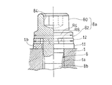
- FIG. 1 is a partially broken front view showing an engine to which a cylinder head bolt fastening structure according to the present invention is applied. It is sectional drawing which shows the state before clamping of the principal part of the fastening structure of the cylinder head bolt which concerns on 1st Embodiment of this invention.
- a cylinder head bolt 8 that has been conventionally used is employed as it is, and the cylinder head 1 and the cylinder 3 are connected to the crankcase 4.
- the shaft portion excluding the rotation operation portion 8a of the cylinder head bolt 8 has an intermediate cylindrical portion 8b as described above, and an outer diameter R1 of the upper end portion where the rotation operation portion 8a is provided.
- a tension bolt having an outer diameter R2 smaller than the outer diameter of the lower end provided with the male screw 8c (FIG. 1).
- the outer diameter of the male screw 8c formed at the lower end portion of the shaft-like portion of the cylinder head bolt 8 is substantially equal to the outer diameter R1 of the upper end portion.
- the cylinder head bolt 8 is a so-called seated bolt, and has a head 80 integrally formed at the upper end of the shaft-like portion and a disk-like collar 82 below the head.
- the head 80 has a hexagonal hole 84 into which a torque wrench for rotating operation is inserted.
- These head 80 and collar 82 form a rotation operation portion 8a.
- the flat washer 11 the thing of the copper plating was given to the surface of the iron-type material conventionally used.
- a flat washer 11 and a disc spring 10 stacked on the flat washer 11 are provided between a collar 82 provided at the lower part of the head 80 of the cylinder head bolt 8 and the upper surface of the cylinder head bolt 8. And are arranged.
- the disc spring 10 is a kind of a spring member that is deformed into a flat shape when the cylinder head bolt 8 is fastened and exhibits a spring force in the axial direction by its restoring force.
- the outer diameter R 4 of the collar 82 of the cylinder head bolt 8, that is, the outer diameter of the rotation operation portion 8 a is slightly larger than the outer diameter R 5 of the disc spring 10 in the free state before the cylinder head bolt 8 is tightened, and the flat washer 11. Is set smaller than the outer shape R3.
- the frictional resistance between the disc spring 10 and the flat washer 11 and the frictional resistance between the flat washer 11 and the cylinder head 1 are also increased, and slippage hardly occurs.
- S2 may be made larger than S3 so that S1 ⁇ S3 ⁇ S2.
- the frictional resistance is influenced by the material and surface roughness in addition to the contact area. Therefore, including these effects, the size of the frictional resistance between the collar 82, the disc spring 10 and the flat washer 11 is set. To do.
- the disc spring 10 is used as a spring member. Since the disc spring 10 is in a free state before the cylinder head bolt 8 is tightened, the disc spring 10 is in line contact with the lower surface of the collar 82 which is the seating surface of the cylinder head bolt 8 at the circular inner peripheral portion, so that the contact area is small. Along with this, the frictional resistance between the disc spring 10 and the collar 82 is also reduced, so that the cylinder head bolt 8 during the tightening operation is easy to rotate while sliding. Further, the disc spring 10 does not have a pointed portion that causes damage when contacting the seating surface of the cylinder head bolt 8 and the flat washer 11. Accordingly, there is an advantage that when a pressing force is applied by tightening the cylinder head bolt 8, it is crushed from above and below and smoothly deformed into a flat shape.
- a cylindrical portion 8b in the middle of the shaft-shaped portion is provided outside the lower end portion provided with the outer diameter R1 of the upper end portion of the shaft-shaped portion provided with the rotation operation portion 8a and the male screw 8c (FIG. 1).
- a tension bolt having an outer diameter R2 smaller than the diameter is used.
- the tension bolt When the cylinder head bolt 8 is fastened, the tension bolt generates a large axial extension in the intermediate cylindrical portion 8b having a small outer diameter R2.
- the tension bolt firmly connects the cylinder head 1 and the engine case 2 of FIG. 1 to each other by the axial force generated in the axial direction with a large tension due to the restoring force.
- the case where the present invention is applied to an engine in which the cylinder 3 and the crankcase 4 constituting the engine case 2 are separated is illustrated.
- the cylinder head bolt 8 is passed through the insertion holes 1 a and 3 a of the cylinder head 1 and the cylinder 3 and screwed into the screw hole 4 a of the crankcase 4.
- the cylinder head 1 and the crankcase 4 can be connected to each other in an arrangement in which the cylinder 3 is sandwiched between them.
- the cylinder head bolt 8 inserted into the insertion hole of the cylinder head 1 is screwed into the screw hole provided in the cylinder 3,
- the cylinder head 1 is fastened to the engine case 2.
- the flat washer 11 a surface of a conventional iron-based material with copper plating is used.
- the flat washer 11 is in a state in which the disc spring 10 bites into the soft copper plating applied thereto, and is difficult to slide with respect to the disc spring 10.
- the slipping portion can be set more reliably between the rotation operation portion 8 a of the cylinder head bolt 8 and the disc spring 10.
- FIGS. 3A and 3B are longitudinal sectional views before and after tightening in a cylinder head bolt fastening structure according to a second embodiment of the present invention, respectively.
- the same or corresponding parts as those in FIGS. 2A and 2B are denoted by the same reference numerals, and redundant description is omitted.
- the fastening structure of this embodiment is different from that of the first embodiment of FIGS. 2A and 2B only in a configuration using a pulling washer 12 as a spring member instead of the disc spring 10 of the first embodiment. is there.
- a flat washer 11 and a spring washer 12 stacked on the flat washer 11 are provided between a collar 82 provided at the lower part of the head 80 of the cylinder head bolt 8 and the upper surface of the cylinder head bolt 8. And are arranged.
- the spring washer 12 is a kind of the spring member 10 that is deformed into a flat shape when the cylinder head bolt 8 is fastened and that expresses a spring force in the axial direction by its restoring force.
- the outer diameter R4 of the flange 82 of the cylinder head bolt 8 is slightly larger than the outer diameter R7 of the spring washer 12 in a free state before the cylinder head bolt 8 is tightened, and the outer shape of the flat washer 11 It is set smaller than R3.
Landscapes
- Engineering & Computer Science (AREA)
- General Engineering & Computer Science (AREA)
- Mechanical Engineering (AREA)
- Chemical & Material Sciences (AREA)
- Combustion & Propulsion (AREA)
- Cylinder Crankcases Of Internal Combustion Engines (AREA)
- Connection Of Plates (AREA)
- Bolts, Nuts, And Washers (AREA)
Priority Applications (3)
| Application Number | Priority Date | Filing Date | Title |
|---|---|---|---|
| CN201480044543.1A CN105452684B (zh) | 2013-08-26 | 2014-07-25 | 气缸盖螺栓的紧固构造 |
| EP14840184.7A EP3040564B1 (en) | 2013-08-26 | 2014-07-25 | Tightening structure for cylinder head bolt |
| US15/012,697 US9897036B2 (en) | 2013-08-26 | 2016-02-01 | Tightening structure for cylinder head bolt |
Applications Claiming Priority (2)
| Application Number | Priority Date | Filing Date | Title |
|---|---|---|---|
| JP2013-174584 | 2013-08-26 | ||
| JP2013174584A JP6178671B2 (ja) | 2013-08-26 | 2013-08-26 | シリンダヘッドボルトの締結構造 |
Related Child Applications (1)
| Application Number | Title | Priority Date | Filing Date |
|---|---|---|---|
| US15/012,697 Continuation US9897036B2 (en) | 2013-08-26 | 2016-02-01 | Tightening structure for cylinder head bolt |
Publications (1)
| Publication Number | Publication Date |
|---|---|
| WO2015029663A1 true WO2015029663A1 (ja) | 2015-03-05 |
Family
ID=52586237
Family Applications (1)
| Application Number | Title | Priority Date | Filing Date |
|---|---|---|---|
| PCT/JP2014/069719 WO2015029663A1 (ja) | 2013-08-26 | 2014-07-25 | シリンダヘッドボルトの締結構造 |
Country Status (5)
| Country | Link |
|---|---|
| US (1) | US9897036B2 (zh) |
| EP (1) | EP3040564B1 (zh) |
| JP (1) | JP6178671B2 (zh) |
| CN (1) | CN105452684B (zh) |
| WO (1) | WO2015029663A1 (zh) |
Cited By (1)
| Publication number | Priority date | Publication date | Assignee | Title |
|---|---|---|---|---|
| US20200047814A1 (en) * | 2018-08-08 | 2020-02-13 | Suzuki Motor Corporation | Assembling structure of engine and vehicle |
Families Citing this family (4)
| Publication number | Priority date | Publication date | Assignee | Title |
|---|---|---|---|---|
| CN106758566A (zh) * | 2017-03-15 | 2017-05-31 | 山东远大特材科技股份有限公司 | 一种镶心式高锰钢辙叉结构 |
| CN108035958A (zh) * | 2018-01-17 | 2018-05-15 | 中国重汽集团济南动力有限公司 | 一种具有安全泄压功能的螺栓组件 |
| US11047417B2 (en) * | 2018-10-11 | 2021-06-29 | GM Global Technology Operations LLC | Fastening assembly |
| EP4421334A1 (en) * | 2023-02-23 | 2024-08-28 | Goodrich Actuation Systems SAS | Threaded fastener |
Citations (4)
| Publication number | Priority date | Publication date | Assignee | Title |
|---|---|---|---|---|
| JPS61136013A (ja) * | 1984-12-06 | 1986-06-23 | 株式会社 佐賀鉄工所 | 座金の共回り防止構造 |
| JPH0240949U (zh) * | 1988-09-13 | 1990-03-20 | ||
| JP3043382U (ja) * | 1997-05-13 | 1997-11-18 | 株式会社音戸工作所 | 座金付きツーピースナット及び座金付きツーピースフランジ付きナット |
| JP2001187911A (ja) * | 1999-12-28 | 2001-07-10 | Fukasawa:Kk | ねじ締結構造 |
Family Cites Families (30)
| Publication number | Priority date | Publication date | Assignee | Title |
|---|---|---|---|---|
| JPS5197603U (zh) * | 1975-02-04 | 1976-08-05 | ||
| NL188659C (nl) | 1975-02-21 | 1992-08-17 | Shell Int Research | Werkwijze voor het ontzwavelen van koolwaterstofolien. |
| US4183699A (en) * | 1978-05-18 | 1980-01-15 | Donan David C Jr | Washer/gasket for mine roof bolt assembly |
| FR2528511A1 (fr) * | 1982-06-14 | 1983-12-16 | Peugeot | Chapeau de palier pour arbre a cames en tete de moteur a combustion interne, et moteur correspondant |
| JPS60180831U (ja) * | 1984-05-10 | 1985-11-30 | アイシン精機株式会社 | ピンスライド型デイスクブレ−キにおけるピンブ−ツの保護構造 |
| US4884930A (en) * | 1987-09-03 | 1989-12-05 | Camloc Gmbh | Panel fastener with friction cones |
| DE3869528D1 (de) * | 1987-09-14 | 1992-04-30 | Sanden Corp | Befestigung eines kraftfahrzeugkompressors fuer eine klimaanlage. |
| US5105777A (en) * | 1988-05-20 | 1992-04-21 | Tecumseh Products Company | Metal head gasket with push rod guides |
| JPH0240949A (ja) | 1988-07-30 | 1990-02-09 | Sony Corp | メモリ装置 |
| US4984938A (en) * | 1988-08-25 | 1991-01-15 | H&S Machine & Supply Company, Inc. | Coated washer for an anchor bolt system |
| CA2122631A1 (en) * | 1991-11-01 | 1993-05-13 | Norman Leslie Matthews | Fastener bearing assembly |
| US5709516A (en) * | 1994-04-18 | 1998-01-20 | General Electric Company | Washer faced spring assembly |
| US5746558A (en) * | 1996-07-24 | 1998-05-05 | Lockheed Martin Corporation | Locking apparatus for fastening system |
| US5730568A (en) * | 1996-10-03 | 1998-03-24 | Mcgard, Inc. | Anti-galling fastener |
| JP3305615B2 (ja) | 1997-04-21 | 2002-07-24 | 本田技研工業株式会社 | ボルト締付け方法 |
| DE29720094U1 (de) * | 1997-11-12 | 1999-03-18 | ITW Automotive Products GmbH & Co. KG, 58642 Iserlohn | Befestigungsvorrichtung |
| US6435791B1 (en) * | 2000-05-19 | 2002-08-20 | Maclean-Fogg Company | Wheel fastener assemblies |
| US7497653B2 (en) * | 2001-08-20 | 2009-03-03 | Maclean-Fogg Company | Locking fastener assembly |
| US6609868B2 (en) * | 2001-12-06 | 2003-08-26 | John K. Junkers | Washer, fastener provided with a washer, and method of fastening with the use of the washer |
| US6827359B2 (en) * | 2002-06-03 | 2004-12-07 | Arvinmeritor Technology, Llc. | Non-drive front axle steering knuckle |
| US6729819B2 (en) * | 2002-07-03 | 2004-05-04 | Applied Bolting Technology Products, Inc. | Bolt lubricating device and method |
| KR20060095123A (ko) * | 2005-02-28 | 2006-08-31 | 주식회사 일진글로벌 | 구동륜의 차축 조립체 |
| AT9916U1 (de) * | 2006-08-16 | 2008-05-15 | Leobersdorfer Maschf | Mehrstufiger verdichter |
| DE102006041860B4 (de) * | 2006-09-06 | 2009-05-14 | Sfs Intec Holding Ag | Schraube und deren Kombination mit einer konischen Dichtscheibe |
| US8171690B2 (en) * | 2008-05-28 | 2012-05-08 | 3Form, Inc. | Countersunk fastener assemblies, panel mounting systems, and methods |
| US8281603B2 (en) * | 2008-08-11 | 2012-10-09 | United Technologies Corporation | Fastener assembly for connecting rocket engine nozzles |
| JP5029537B2 (ja) * | 2008-08-26 | 2012-09-19 | 三菱自動車工業株式会社 | エンジン本体構造 |
| DE102009023721A1 (de) * | 2009-06-03 | 2010-12-09 | Neumayer Tekfor Holding Gmbh | Befestigungsvorrichtung |
| JP5903852B2 (ja) * | 2011-11-29 | 2016-04-13 | スズキ株式会社 | 内燃機関のクランクケース構造 |
| DE102012100228A1 (de) * | 2012-01-12 | 2013-07-18 | Kamax Holding Gmbh & Co. Kg | Schraube mit einer Kopfauflagefläche mit Schmiermitteltaschen |
-
2013
- 2013-08-26 JP JP2013174584A patent/JP6178671B2/ja active Active
-
2014
- 2014-07-25 CN CN201480044543.1A patent/CN105452684B/zh not_active Expired - Fee Related
- 2014-07-25 EP EP14840184.7A patent/EP3040564B1/en active Active
- 2014-07-25 WO PCT/JP2014/069719 patent/WO2015029663A1/ja active Application Filing
-
2016
- 2016-02-01 US US15/012,697 patent/US9897036B2/en not_active Expired - Fee Related
Patent Citations (4)
| Publication number | Priority date | Publication date | Assignee | Title |
|---|---|---|---|---|
| JPS61136013A (ja) * | 1984-12-06 | 1986-06-23 | 株式会社 佐賀鉄工所 | 座金の共回り防止構造 |
| JPH0240949U (zh) * | 1988-09-13 | 1990-03-20 | ||
| JP3043382U (ja) * | 1997-05-13 | 1997-11-18 | 株式会社音戸工作所 | 座金付きツーピースナット及び座金付きツーピースフランジ付きナット |
| JP2001187911A (ja) * | 1999-12-28 | 2001-07-10 | Fukasawa:Kk | ねじ締結構造 |
Cited By (2)
| Publication number | Priority date | Publication date | Assignee | Title |
|---|---|---|---|---|
| US20200047814A1 (en) * | 2018-08-08 | 2020-02-13 | Suzuki Motor Corporation | Assembling structure of engine and vehicle |
| US10960930B2 (en) * | 2018-08-08 | 2021-03-30 | Suzuki Motor Corporation | Assembling structure of engine and vehicle |
Also Published As
| Publication number | Publication date |
|---|---|
| CN105452684B (zh) | 2018-01-30 |
| EP3040564A1 (en) | 2016-07-06 |
| EP3040564B1 (en) | 2020-12-30 |
| CN105452684A (zh) | 2016-03-30 |
| EP3040564A4 (en) | 2017-04-05 |
| US9897036B2 (en) | 2018-02-20 |
| US20160146149A1 (en) | 2016-05-26 |
| JP2015042887A (ja) | 2015-03-05 |
| JP6178671B2 (ja) | 2017-08-09 |
Similar Documents
| Publication | Publication Date | Title |
|---|---|---|
| WO2015029663A1 (ja) | シリンダヘッドボルトの締結構造 | |
| JP2015515589A (ja) | 改善された振動および締結特性を有する締結具および締結具組立体 | |
| US9322426B2 (en) | Nut and sleeve fastener | |
| JP5787197B2 (ja) | 締結部材 | |
| WO2018154795A1 (ja) | 締結構造 | |
| TWI580603B (zh) | 自行車用鏈輪 | |
| JP2015203492A (ja) | 緩み止めナット | |
| KR20160003315A (ko) | 풀림 방지 나사산 부재 | |
| JP6039841B1 (ja) | 緩み止めナット | |
| KR101628978B1 (ko) | 풀림방지 와셔 | |
| WO2015146722A1 (ja) | ショックアブソーバの製造方法 | |
| JP6094347B2 (ja) | ボールねじ装置用ロックナット及びボールねじ装置 | |
| JP6055079B2 (ja) | 取付構造 | |
| JP6295102B2 (ja) | スタッドボルト弛め具 | |
| JP5817039B2 (ja) | 弛み止め締付部材又は弛み止め座金 | |
| JP2015075235A (ja) | 締結部材 | |
| JP2014219093A (ja) | 締結部材 | |
| US20160348702A1 (en) | Device configured for preloading bearing interfaces coupling concentrically arranged tubes | |
| JP2006189065A (ja) | 取付構造 | |
| JP3179117U (ja) | ナットの緩み止めワッシャー | |
| JP5802772B2 (ja) | ナット及びナット締め付け具並びにボルト及びボルト締め付け具 | |
| TW201544720A (zh) | 螺帽 | |
| JP5451548B2 (ja) | 袋ナット | |
| JP3183487U (ja) | 軸力表示座金付ナット | |
| JP2016161126A (ja) | 締結ナット用脱落防止装置 |
Legal Events
| Date | Code | Title | Description |
|---|---|---|---|
| WWE | Wipo information: entry into national phase |
Ref document number: 201480044543.1 Country of ref document: CN |
|
| 121 | Ep: the epo has been informed by wipo that ep was designated in this application |
Ref document number: 14840184 Country of ref document: EP Kind code of ref document: A1 |
|
| REEP | Request for entry into the european phase |
Ref document number: 2014840184 Country of ref document: EP |
|
| WWE | Wipo information: entry into national phase |
Ref document number: 2014840184 Country of ref document: EP |
|
| NENP | Non-entry into the national phase |
Ref country code: DE |