WO2015029413A1 - アイソレータシステム及びその制御システム - Google Patents
アイソレータシステム及びその制御システム Download PDFInfo
- Publication number
- WO2015029413A1 WO2015029413A1 PCT/JP2014/004357 JP2014004357W WO2015029413A1 WO 2015029413 A1 WO2015029413 A1 WO 2015029413A1 JP 2014004357 W JP2014004357 W JP 2014004357W WO 2015029413 A1 WO2015029413 A1 WO 2015029413A1
- Authority
- WO
- WIPO (PCT)
- Prior art keywords
- unit
- air conditioning
- display
- operator
- control unit
- Prior art date
- Legal status (The legal status is an assumption and is not a legal conclusion. Google has not performed a legal analysis and makes no representation as to the accuracy of the status listed.)
- Ceased
Links
Images





Classifications
-
- C—CHEMISTRY; METALLURGY
- C12—BIOCHEMISTRY; BEER; SPIRITS; WINE; VINEGAR; MICROBIOLOGY; ENZYMOLOGY; MUTATION OR GENETIC ENGINEERING
- C12M—APPARATUS FOR ENZYMOLOGY OR MICROBIOLOGY; APPARATUS FOR CULTURING MICROORGANISMS FOR PRODUCING BIOMASS, FOR GROWING CELLS OR FOR OBTAINING FERMENTATION OR METABOLIC PRODUCTS, i.e. BIOREACTORS OR FERMENTERS
- C12M37/00—Means for sterilizing, maintaining sterile conditions or avoiding chemical or biological contamination
-
- A—HUMAN NECESSITIES
- A61—MEDICAL OR VETERINARY SCIENCE; HYGIENE
- A61L—METHODS OR APPARATUS FOR STERILISING MATERIALS OR OBJECTS IN GENERAL; DISINFECTION, STERILISATION OR DEODORISATION OF AIR; CHEMICAL ASPECTS OF BANDAGES, DRESSINGS, ABSORBENT PADS OR SURGICAL ARTICLES; MATERIALS FOR BANDAGES, DRESSINGS, ABSORBENT PADS OR SURGICAL ARTICLES
- A61L2/00—Disinfection or sterilisation of materials or objects, in general; Accessories therefor
- A61L2/16—Disinfection or sterilisation of materials or objects, in general; Accessories therefor using chemical substances
- A61L2/22—Phase substances, e.g. smokes or aerosols
Definitions
- the present disclosure relates to an isolator system used for regenerative medicine-related and pharmaceutical-related experiments and a control system thereof.
- Patent Document 1 discloses an isolator for performing work on biological material.
- the isolator includes a work room, a reader that reads information from a wireless tag that stores information associated with an operation target, and a work management unit that acquires information read by the reader and manages work.
- the isolator also includes a monitor that displays an operation menu of the device to the operator. Thereby, the working efficiency in the isolator is improved.
- This disclosure provides an isolator system and a control system thereof that can improve the safety of workers.
- An isolator system includes a work space for performing work in an aseptic environment, a box-shaped main body case having an insertion portion into which an operator's arm is inserted on the front surface, and a sterilizing substance to supply the work space.
- the control unit displays the visual inspection items for visual inspection by the operator and the visual confirmation input unit for the operator to complete the visual inspection on the display unit after starting and before operating the air conditioning unit. After the input to the visual confirmation input unit, the operation check of the air conditioning unit is performed, and the state of the operation check of the air conditioning unit is displayed on the display unit.
- control system includes a work space for performing work in an aseptic environment, a box-shaped main body case having an insertion portion into which an operator's arm is inserted, and a sterilizing substance.
- a control system that controls an isolator system including a sterilization unit that sterilizes a space, an air conditioning unit that supplies and exhausts the work space, and a display unit through which an operator can input a signal.
- the control system displays on the display section visual inspection items that the operator performs visual inspection and a visual confirmation input section that allows the operator to input the completion of visual inspection after starting and before operating the air conditioning unit. After the input to the visual confirmation input unit, the operation check of the air conditioning unit is performed, and the state of the operation check of the air conditioning unit is displayed on the display unit.
- the isolator system and the control system according to the present disclosure can improve the safety of the worker.
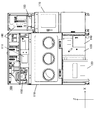
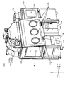
- Front view of isolator system according to Embodiment 1 1 is a perspective view of an isolator system according to Embodiment 1.
- FIG. The perspective view of the isolator system at the time of the incubator installation which concerns on Embodiment 1 Schematic showing the configuration of the isolator system according to the first embodiment 1 is a block diagram showing a configuration of an isolator system according to a first embodiment. The figure which shows the top menu screen after starting of the isolator system which concerns on Embodiment 1.
- FIG. 1 Flowchart for explaining the pre-start inspection of the isolator system according to the first embodiment
- the isolator system 100 according to Embodiment 1 is an apparatus for performing work such as cell culture, operation, and observation in a sterile environment.
- sterilization refers to sterilization of microorganisms, cells, and the like to bring them closer to sterility.
- the Z-axis is an axis along the vertical direction in which the isolator system 100 is erected.
- the direction toward the upper side (upward) is the + Z direction
- the direction toward the lower side (downward) is the ⁇ Z direction.
- the Y axis is an axis along a direction substantially orthogonal to the front and back surfaces of the isolator system 100, and is a direction from the front surface provided with an opening for performing work in the work space to the back surface opposite to the front surface. Is the ⁇ Y direction, and the direction from the back to the front is the + Y direction.
- the X-axis is an axis along a direction substantially orthogonal to the left and right side surfaces when viewed from the front, the direction from the left side to the right side as viewed from the front is the + X direction, and the direction from the right side to the left side is -X The direction.
- FIGS. 1 and 2 are a front view and a perspective view of the isolator system 100 according to the first embodiment.
- the isolator system 100 includes a glove box 110, a centrifuge unit 120, an observation unit 130, a sterilization unit 140, an air conditioning unit 150, a control unit 160, a pass box 170, an air conditioning unit 180, and Diffusion fans 191 and 192 (FIG. 4) are provided.
- the glove box 110 has a display 111 for displaying the operation of the apparatus and the state of the apparatus at the upper front part.
- the display 111 is connected to a control unit 160 provided at the upper front. An operator can input a signal to the display 111.
- the glove box 110 forms a substantially box-shaped work space A that constitutes a sterile environment isolated from the surroundings.
- the glove box 110 includes a front door 112 provided with a plurality of openings 113 on the front surface.
- the glove box 110 is partitioned with airtightness so that entry of bacteria from the outside is suppressed.
- ducts for exhausting the gas in the work space A are formed below the work table on which work is performed and on the back side of the work space A.
- the glove box 110 of the present embodiment is made of a stainless steel plate that is easy to clean and disinfect.
- the front door 112 is provided with a plurality of openings 113 into which an operator's arm is inserted on the front surface, and a glove (not shown) is attached to each of the plurality of openings 113.
- the front door 112 can be opened and closed with a hinge provided at the upper end as an axis. Thereby, the front surface of the glove box 110 can be opened and closed.
- a handle 114 with a lock that can lock the opening and closing of the front door 112 is provided below the front door 112.
- the operator can unlock the lock handle 114 and open the front door 112 by pulling the handle 114 with the lock.
- the work space A is sealed by locking the handle 114 with lock after the front door 112 is pushed down.
- the centrifuge unit 120 is provided below the glove box 110 and can be connected from the work space A.
- the centrifuge unit 120 includes therein a centrifuge for centrifuging a sample to be worked in the work space A.
- the observation unit 130 is provided below the glove box 110 and can be connected from the work space A.
- the observation unit 130 includes an observation device for observing a sample working in the work space A.
- the observation unit 130 includes an elevating mechanism that can elevate an observation apparatus provided inside, and a handle that is provided outside and operates the elevating mechanism. By operating the lifting mechanism with the handle, the operator pushes up the observation device into the working space A when using the observation device, and accommodates the observation device in the observation unit 130 when the observation device is not used. it can.
- FIG. 3 is a perspective view of the isolator system 100 when the incubator 200 according to the first embodiment is mounted.
- the incubator 200 is mounted on the side surface of the glove box 110 opposite to the side surface on which the pass box 170 is provided.
- the incubator 200 includes a storage chamber (not shown) therein.
- This storage chamber is a chamber for storing a culture, and is partitioned as a space in which entry of bacteria from the outside is suppressed by a rectangular parallelepiped box, for example.
- the accommodation chamber is partitioned by, for example, a stainless steel plate.
- the incubator 200 is configured to be detachable from the isolator system 100. Thereby, the culture can be managed for each incubator 200. For example, by using a dedicated incubator 200 for each donor, it is possible to suppress problems such as mix-up of cultures.
- the sterilization unit 140 is provided in the lower part of the glove box 110 in order to supply a sterilizing substance and sterilize the work space A of the glove box 110.
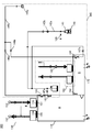
- FIG. 4 is a schematic diagram showing the configuration of the isolator system 100 according to the first embodiment. As shown in FIG. 4, the sterilization unit 140 absorbs the sterilizing liquid bottle 141, the electronic balance 148 that measures the weight of the sterilizing liquid bottle 141, and the sterilizing liquid bottle 141 and supplies the sterilizing liquid to the nozzle 143 or the nozzle 144. And a peristaltic pump 142b.
- the sterilization unit 140 includes a nozzle 143 provided in the glove box 110 and a nozzle 144 provided in the pass box 170.
- the sterilization unit 140 includes a compressor 145 a and an air supply pipe 145 b that supply air to the nozzle 143 or the nozzle 144.
- the sterilization unit 140 includes an air supply valve 149 for introducing air into the water absorption pipe 142a.
- the air supply valve 149 is provided between the tip of the water suction pipe 142a inserted into the sterilizing liquid bottle 141 and the peristaltic pump 142b.
- the flow of air into the nozzle 143 or the nozzle 144 is controlled by opening and closing the switching valve 146a and the switching valve 146b.
- By opening and closing the switching valve 147a and the switching valve 147b the inflow of the sterilizing liquid into the nozzle 143 or the nozzle 144 is controlled.
- the sterilizing solution for example, hydrogen peroxide water is used.
- the sterilizing liquid is stored in the sterilizing liquid bottle 141, and the sterilizing liquid bottle 141 is placed on a measuring means such as an electronic balance 148.
- the electronic balance 148 measures the weight of the sterilizing liquid bottle 141 and the sterilizing liquid, and the signal is input to the control unit 160.
- the sterilization liquid stored in the sterilization liquid bottle 141 is supplied to the nozzle 143 or the nozzle 144 via the water absorption pipe 142a by a liquid feeding means such as a peristaltic pump 142b.
- the hydrogen peroxide solution in the sterilizing liquid bottle 141 is gradually supplied to the nozzle 143 or the nozzle 144 by the peristaltic pump 142b.
- the peristaltic pump 142b is provided in the middle of the water absorption pipe 142a, and a filter for removing foreign substances is provided downstream of the peristaltic pump 142b. Between the filter and the peristaltic pump 142b, a pressure sensor for detecting the pressure in the water suction pipe 142a is provided. The clogging of the filter can be monitored by the pressure sensor, or abnormality such as bending of the water absorption pipe 142a can be detected. Since the control unit 160 receives signals from the electronic balance 148 and the pressure sensor, the control unit 160 can control the driving of the peristaltic pump 142b and the opening / closing of the air supply valve 149.
- the supply pipe 145 b has one end attached to the compressor 145 a and the other end attached to the nozzle 143 or the nozzle 144. Thereby, the compressor 145a can supply air to the nozzle 143 or the nozzle 144 through the air supply pipe 145b.
- the air conditioning unit 150 is provided in the upper part of the glove box 110 and controls supply and exhaust of the work space A.
- the air conditioning unit 150 includes an air supply unit 150a and an exhaust unit 150b.
- the air conditioning unit 150 includes an air supply port 151 and an exhaust port 155 provided on the upper surface plate in the glove box 110. Air is supplied from the air supply port 151 into the glove box 110, and air is discharged from the exhaust port 155.
- a particulate collection filter of the HEPA filter 152 is provided in the air supply port 151, and air is supplied into the glove box 110 through the particulate collection filter.
- the exhaust port 155 is also provided with a HEPA filter 156, and the gas in the glove box 110 is exhausted from the glove box 110 through the HEPA filter 156.
- a sterilization process is performed in which a sterilizing substance such as hydrogen peroxide is sprayed inside to sterilize the inside of the glove box 110.
- FIG. 5 is a block diagram showing the configuration of the isolator system 100 according to the first embodiment.
- the control unit 160 is connected to the memory 162, the display 111, the lock handle 114, the sterilization unit 140, the air conditioning unit 150, the air conditioning unit 180 (FIG. 3), and the diffusion fans 191 and 192 (FIG. 4).
- the memory 162 stores a signal transmitted from the control unit 160.
- the display 111 displays a signal transmitted from the control unit 160.
- the handle with lock 114 locks or unlocks the opening / closing of the front door 112 based on a signal transmitted from the control unit 160.
- a signal is output to each component of the sterilization unit 140 in accordance with an input from the electronic balance 148 or the like.
- the sterilization unit 140 operates each part based on the signal transmitted from the control unit 160 to spray sterilization mist.
- the air conditioning unit 150 and the air conditioning unit 180 control the air supply blower 153, the exhaust blower 157, and the air supply blower 183 based on the signal transmitted from the control unit 160 to supply the outside air and exhaust the inside air.
- the diffusion fans 191 and 192 are controlled based on a signal transmitted from the control unit 160.
- the control unit 160 performs operation control of the apparatus such as a pre-work inspection for inspecting the apparatus and a sterilization process for sterilizing the inside of the glove box 110.
- the pre-start inspection is a process of inspecting each part after starting the apparatus and before operating each part.
- the sterilization process includes a spraying process, an exposure process, and a detoxification process.
- the spraying step is a step of sterilizing by spraying a sterilized mist (sterilizing substance) into the glove box 110.
- the exposure step is a step of sterilizing the sprayed sterilized mist by diffusing it to every corner of the glove box 110.
- the detoxification step is a step of supplying air into the glove box 110 and exhausting the gas in the glove box 110 to replace the gas in the glove box 110 to reduce the concentration of the sterilizing substance in the work space A. is there.
- the pass box 170 is provided on the side surface of the glove box 110 so that the worker can put the work into the work space A from the outside.
- a conveyance space B for temporarily storing work is formed inside the pass box 170.
- the conveyance space B is airtight with respect to the surrounding environment.
- An opening for moving the work is provided on the side surface of the pass box 170, and the glove box 110 and the pass box 170 are fixed to face the opening provided on the side surface of the glove box 110.
- the work space A and the transfer space B communicate with each other with airtightness.
- An openable / closable door is attached to the opening of the pass box 170.
- the door can separate the conveyance space B from the work space A with airtightness.
- the air conditioning unit 180 is provided in the upper part of the pass box 170, and controls the air conditioning in the conveyance space B inside.
- the isolator system 100 includes diffusion fans 191 and 192.
- a diffusion fan 191 is provided in the glove box 110, and a diffusion fan 192 is provided in the pass box 170.
- the diffusion fan 191 diffuses the gas in the work space A, and the diffusion fan 192 diffuses the gas in the transfer space B.
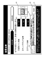
- FIG. 6 is a diagram showing a top menu screen after the isolator system 100 according to the first embodiment is activated.
- the control unit 160 When the isolator system 100 is activated, the control unit 160 first displays a top menu screen as shown in FIG. The operator selects a menu to be operated from the top menu screen and operates the isolator system 100. On the top new screen, an [End] button B1 for ending the operation of the isolator system 100, a [Pre-start inspection] button B2 for inspecting the apparatus, an [Operation menu] button B3 for performing operations such as sterilization, A [Data setting] button B4 for setting various data and an [Authentication] button B5 for authenticating the worker are displayed.
- an [End] button B1 for ending the operation of the isolator system 100
- a [Pre-start inspection] button B2 for inspecting the apparatus
- an [Operation menu] button B3 for performing operations such as sterilization
- a [Data setting] button B4 for setting various data
- an [Authentication] button B5 for authenticating the worker are displayed.
- FIG. 7 is a flowchart for explaining the pre-start inspection of the isolator system 100 according to the first embodiment.
- the control unit 160 first confirms whether or not the previous operation ended with a normal operation (S101).
- the end of normal operation refers to the case where the operator instructs to end the operation and ends.
- the end of the abnormal operation refers to a case where the power supply to the apparatus is interrupted due to a power failure due to lightning, and the apparatus is forcibly shut down.
- the front door 112 is locked by the handle 114 with a lock when the power is turned off. Therefore, the isolator system 100 is in a state where the lock handle 114 is locked at the time of activation.
- FIG. 8 is a diagram showing a normal hydrogen peroxide concentration confirmation screen in the pre-start inspection of the isolator system 100 according to the first embodiment.
- the measurement instruction of the hydrogen peroxide concentration to the worker the question asking whether the concentration of hydrogen peroxide is below a predetermined concentration, and the answer to the question [YES] button B7 and [NO] button B8 (density confirmation input section) are displayed.
- a [Top New] button B6 for returning to the top menu screen shown in FIG. 6 and an operation explanation column A1 describing the operator's operation method are also displayed on the screen.
- FIG. 9 is a diagram showing a hydrogen peroxide concentration confirmation screen at the time of the previous abnormal end in the pre-start inspection of the isolator system 100 according to the first embodiment.
- an operator's notes column A2 is added to the normal screen shown in FIG. This is because the hydrogen peroxide concentration in the glove box 110 may be high in the case of abnormal end of operation such as a power failure during the sterilization process, for example, so that the precautions column A2 is displayed and the work is performed. This is to call attention to the person.
- the operator measures the concentration of hydrogen peroxide remaining in the work space A using the hydrogen peroxide gas detection tube, and the result is displayed on the display 111. input.
- the control unit 160 stores a “concentration Hi flag” indicating that the hydrogen peroxide concentration in the glove box 110 is high. 162, the apparatus inspection screen shown in FIG. 10 is displayed on the display 111 (S104, S105, S106).
- the control unit 160 causes the display 111 to display the apparatus inspection screen shown in FIG. 10 without storing the “density Hi flag” in the memory 162 (S104). , S106).
- the control unit 160 can unlock the handle with lock 114 and open and close the front door 112. It becomes.
- the control unit 160 does not unlock the handle 114 with lock, and the opening / closing of the front door 112 remains locked.
- FIG. 10 and 11 are diagrams showing an apparatus inspection screen at the time of visual inspection in the pre-start inspection of the isolator system 100 according to the first embodiment.
- the pre-work inspection includes visual inspection and automatic inspection
- the control unit 160 first displays on the display 111 visual inspection items that the operator visually inspects the apparatus (S106). ).
- a confirmation button B10 visual confirmation input unit
- the display switches from “NG” indicating that the inspection is not completed to “OK” indicating that the inspection is completed.
- a [Next] button B9 for inputting completion of inspection of the visual inspection item is displayed on the apparatus inspection screen. As shown in FIG.
- the [Next] button B9 becomes effective when the visual inspection item is switched to the display of “OK”.
- [Next] button B9 becomes effective when there are a plurality of items to be visually inspected and all of the plurality of confirmation buttons B10 are switched to the display of “OK”. That is, the operator cannot input to the [Next] button B9 if there is at least one “NG” in the plurality of confirmation buttons B10, and switches all of the confirmation buttons B10 to “OK” to [Next]. It is possible to input to the button B9. If there is even one “NG” on the confirmation button B10 on the visual inspection screen, the control unit 160 maintains the display of the screen.
- the control unit 160 displays an abnormal screen including the “NG” confirmation button B10 indicating that the visual inspection item is incomplete or the visual inspection item is abnormal (S107, S108). Thereby, the control unit 160 can indicate to the operator that there is a possibility that the visual inspection item is abnormal.
- the control unit 160 displays the next device inspection screen shown in FIG. 12 on the display 111 (S107, S109).
- a guide diagram A3 indicating where the visual inspection item hits the isolator system 100 is displayed. Thereby, an operator's workability
- FIG. 12 to 15 are diagrams showing an apparatus inspection screen at the time of automatic inspection in the pre-start inspection of the isolator system 100 according to the first embodiment.
- the control unit 160 performs an automatic inspection for inspecting items other than the visual inspection items.
- the control unit 160 causes the display 111 to display guidance for allowing the operator to confirm a predetermined item as preparation before inspection.
- the control unit 160 checks whether or not the predetermined item satisfies the condition, and displays whether or not the predetermined item satisfies the condition on the same screen.
- the control unit 160 displays a [Next] button B9 that becomes effective when a predetermined item satisfies all the conditions, as in the apparatus inspection screen during visual inspection.
- the control unit 160 When the operator inputs to the [Next] button B9, the control unit 160 causes the display 111 to display an apparatus inspection screen for automatic inspection shown in FIG. 13 (S109). Although not shown in FIG. 7, in this embodiment, when the operator inputs the [Next] button B ⁇ b> 9, the control unit 160 opens and closes the front door 112 by the handle 114 with a lock. Lock it.
- the control unit 160 displays target items to be inspected and inspection results for each target item (including a display indicating that the inspection is being performed).
- the control unit 160 displays a [Next] button B9 that becomes effective when all of the inspection target items are normal, as in the apparatus inspection screen during visual inspection.
- the control unit 160 maintains the display of the screen when there is at least one “NG” in the inspection result of the inspection target item on the apparatus inspection screen during the automatic inspection. That is, the control unit 160 displays an abnormal screen indicating that the inspection target item is abnormal (S110, S111). Thereby, the control unit 160 can indicate to the operator that there is an abnormality in the automatic inspection item.
- control unit 160 checks whether or not the “density Hi flag” is stored in the memory 162 (S112).
- the control unit 160 transmits an operation start signal to the air conditioning unit 150 to start the harmless process (S113).
- the detoxification process started here is the same process as the detoxification process performed in the sterilization process.
- the control unit 160 has a counter and measures whether or not a predetermined time has elapsed (S114). When the predetermined time has elapsed, the control unit 160 displays a screen similar to the hydrogen peroxide concentration confirmation screen shown in FIG. 8 on the display 111 (S115). If the [YES] button B7 is selected by the operator, the control unit 160 transmits an operation stop signal to the air conditioning unit 150 and ends the detoxification process (S116).
- the control unit 160 starts measurement for a predetermined time again.
- the hydrogen peroxide concentration confirmation screen is displayed again (S115).
- the control unit 160 repeats this operation until the [YES] button B7 is selected.
- the control unit 160 unlocks the lock handle 114 and ends the pre-work inspection (S117).
- the control unit 160 unlocks the handle 114 with lock and ends the pre-work inspection (S117).
- the isolator system 100 includes a box-like glove box 110 (an insertion space) in which a work space A in an aseptic environment is inserted and an operator's arm is inserted in the front.
- a main body case a sterilization unit 140 (sterilization unit) that supplies hydrogen peroxide (sterilizing substance) to sterilize the work space A, an air conditioning unit 150 (air conditioning unit) that supplies and exhausts the work space A, and a worker Includes a display 111 (display unit) capable of inputting a signal, a sterilization unit 140, an air conditioning unit 150, and a control unit 160 (control unit) connected to the display 111.
- FIG. 1 Before operating the air conditioning unit 150, FIG.
- FIG. 11 shows the visual inspection items that the operator visually checks the operation and the operator inputs the completion of the operational inspection.
- Next] button B9 (visual confirmation input unit) is displayed on display 111.
- the operation check of air conditioning unit 150 is performed, and the state of the operation check of air conditioning unit 150 is displayed on display 111. Display.
- the operation check of the air conditioning unit 150 includes, for example, a leak test for confirming whether the work space A is kept airtight.
- the air conditioning unit 150 can be operated after visual inspection. it can. Therefore, it is possible to provide an isolator system capable of reliably inspecting the apparatus even when a sterilizing substance remains in the interior at the start-up and reducing the danger of the operator.
- the air-conditioning unit 150 when the air-conditioning unit 150 is operated by starting an automatic inspection or an experimental environment operation without performing a visual inspection at the time of start-up, if the airtightness of the work space A is not maintained due to some problem, the sterilizing substance is externally applied. Leaks, putting workers at risk. For example, it is conceivable that the globe is damaged or the front door 112 is cracked.
- the control unit 160 when there is no problem as a result of the operation check of the air conditioning unit 150, the control unit 160 allows the operator to input the completion of the operation check [Next] button B9 (air condition confirmation) shown in FIG.
- the input unit is displayed on the display 111, and when there is a problem, a screen displaying the problem is displayed on the display unit (S111 in FIG. 7).
- the isolator system 100 includes a front door 112 attached to the front surface of the glove box 110 so as to be openable and closable, and a handle 114 with a lock capable of locking the opening and closing of the front door 112 by a signal from the control unit 160.
- the concentration of hydrogen peroxide in the work space A is predetermined.
- the lock handle 114 is unlocked and the front door 112 can be opened and closed.
- the concentration of hydrogen peroxide in the work space A exceeds a predetermined concentration, the lock handle 114 is locked and the front door 112 is locked. The door 112 cannot be opened and closed.
- the isolator system which can reduce a worker's danger can be provided.
- control unit 160 (control system) includes a box-like glove box 110 having a work space A in an aseptic environment inside and an opening 113 (insertion portion) into which an operator's arm is inserted in the front. (Main body case), a sterilization unit 140 (sterilization unit) that supplies hydrogen peroxide (sterilizing substance) to sterilize the working space A, an air conditioning unit 150 (air conditioning unit) that supplies and exhausts the work space A, And a display 111 (display unit) through which a person can input a signal, and controls the isolator system 100.
- the control unit 160 after starting, before operating the air conditioning unit 150, the visual inspection items that the operator visually checks the operation and the [Next] button B9 shown in FIG. (Air conditioning confirmation input unit) is displayed on the display unit, and after inputting to the [Next] button B9, the operation check of the air conditioning unit 150 is performed, and the state of the operation check of the air conditioning unit 150 is displayed on the display 111.
- the control unit 160 is operated after visual inspection. Can be made. Therefore, it is possible to provide a control system for an isolator system that can surely inspect the apparatus even when a sterilizing substance remains in the interior at the time of activation, and can reduce the danger of the operator.
- control unit 160 when the control unit 160 is operated by starting an automatic inspection or an experimental environment operation without performing a visual inspection at the time of start-up, if the airtightness of the work space A is not maintained due to some problem, the sterilizing substance is externally applied. Leaks, putting workers at risk. For example, it is conceivable that the globe is damaged or the front door 112 is cracked.
- the control unit 160 when there is no problem as a result of the operation check of the air conditioning unit 150, the control unit 160 allows the operator to input the completion of the operation check [Next] button B9 (air condition confirmation) shown in FIG.
- the input unit is displayed on the display 111, and when there is a problem, a screen displaying the problem is displayed on the display unit (S111 in FIG. 7).
- the control system of the isolator system which can reduce a worker's danger can be provided.
- the isolator system 100 includes a front door 112 attached to the front surface of the glove box 110 so as to be openable and closable, and a handle 114 with a lock capable of locking the opening and closing of the front door 112 by a signal from the control unit 160.
- the concentration of hydrogen peroxide in the work space A is predetermined.
- the lock handle 114 is unlocked and the front door 112 can be opened and closed.
- the concentration of hydrogen peroxide in the work space A exceeds a predetermined concentration, the lock handle 114 is locked and the front door 112 is locked. The door 112 cannot be opened and closed.
- the control system of the isolator system which can reduce a worker's danger can be provided.
- FIG. 15 is a flowchart for explaining the pre-start inspection of the isolator system 101 according to the second embodiment.
- the control unit 160 first displays a top menu screen as shown in FIG. The operator selects a menu to be operated from the top menu screen and operates the isolator system 101. On the top new screen, an [End] button B1 for ending the operation of the isolator system 101, a [Pre-start inspection] button B2 for inspecting the apparatus, an [Operation menu] button B3 for performing sterilization, etc., and various data Are displayed, and B5 for performing worker authentication is displayed.
- the pre-start inspection for inspecting the apparatus is basically similar to the isolator system 100 of the first embodiment, the difference from the operation of the isolator system 100 will be described with emphasis.
- control unit 160 first confirms whether or not the previous operation ended with a normal operation (S201).
- the control unit 160 displays the screen shown in FIG. 8 on the display 111 when the previous operation ends with a normal operation (S202).
- control unit 160 stores an “abnormal flag” in the memory 162 indicating that the previous operation end is abnormal when the previous operation end is not normal operation, that is, at the previous abnormal end. Then, the screen shown in FIG. 9 is displayed on the display 111 (S203, S204).
- next apparatus inspection process (S205 to S212) is the same as the apparatus inspection process (S104 to S111) of the first embodiment, and the description thereof will be omitted.
- control unit 160 checks whether or not the “density Hi flag” is stored in the memory 162 (S213).
- the control unit 160 When the “density Hi flag” is stored in the memory 162, the control unit 160 confirms whether or not the “abnormal flag” is stored in the memory 162 (S214). Thereafter, an operation start signal is transmitted to the air conditioning unit 150 to start the detoxification process (S215, S218).
- the control unit 160 has a counter and measures whether or not a predetermined time has elapsed (S216, S219). At this time, the control unit 160 sets the predetermined time when the “abnormal flag” is stored in the memory 162 longer than the predetermined time when the “abnormal flag” is not stored in the memory 162. When the predetermined time has elapsed, the control unit 160 displays a screen similar to the hydrogen peroxide concentration confirmation screen shown in FIG.
- the control unit 160 transmits an operation stop signal to the air conditioning unit 150, and ends the harmless process (S221).
- the control unit 160 starts measurement for a predetermined time again.
- the predetermined time has elapsed, the hydrogen peroxide concentration confirmation screen is displayed again (S216, S219).
- the control unit 160 repeats this operation until the [YES] button B7 is selected.
- the predetermined time for repeating may be shorter than the predetermined time one time before. Thereby, the time of the detoxification process can be shortened.
- the control unit 160 releases the lock of the handle 114 with lock, and ends the pre-work inspection (S222).
- the control unit 160 unlocks the handle 114 with the lock, and ends the pre-start inspection (S222).
- control unit 160 performs the predetermined time when the “abnormal flag” is stored in the memory 162 and the predetermined time when the “abnormal flag” is not stored in the memory 162. Set longer.
- control unit 160 sets a longer time for the detoxification process, and thus can further improve the safety of the operator. Therefore, a highly safe isolator system and its control system can be provided.
- Embodiments 1 and 2 have been described as examples of the technology disclosed in the present application. However, the technology in the present disclosure is not limited to this, and can also be applied to embodiments in which changes, replacements, additions, omissions, and the like have been made as appropriate. In addition, it is possible to combine the components described in the first and second embodiments to form a new embodiment.
- the glove box 110 has been described as an example of the main body case. Since the glove box 110 has an object to be visually inspected by an operator such as a glove inspection, the safety of the operator can be improved.
- the main body case is not limited to the glove box 110.
- the technology of the present disclosure may be used for the pass box 170.
- the disclosed technology may be used for a plurality of isolator systems. You can also use the technology disclosed in safety cabinets and clean benches.
- the main body case may be an apparatus that constitutes a work space.
- the sterilization unit 140 has been described as an example of a sterilization unit. Since the sterilization unit 140 is configured to eject a mist-like sterilization mist from the nozzle, the sterilization processing time can be shortened.
- the sterilization unit is not limited to the sterilization unit 140.
- a sterilizing substance may be heated with a heater to supply a gasified sterilizing gas.
- a sterilized mist obtained by mist-sterilizing a sterilizing substance may be supplied using an ultrasonic vibrator. Further, the sterilized mist once misted may be heated and gasified with a heater.
- the sterilization unit may be any device that can supply a sterilizing substance into the work space and sterilize the work space.
- the detoxification process in the first and second embodiments, air is supplied into the glove box 110 and the gas in the glove box 110 is exhausted to replace the gas in the glove box 110, so that The concentration of sterilizing substances is reduced.
- the detoxification process is not limited to this process.
- a step of providing a sterilizing substance reducing means such as a catalyst in the circulation path where the gas exhausted from the work space A returns to the work space A and circulating the gas in the work space A through the circulation path may be employed.
- the operator uses a detection tube to measure and input the result. It is not limited to the configuration. For example, a densitometer or a density sensor may be used.
- a concentration sensor the operator does not need to measure the concentration and input the result, so the control unit 160 displays the hydrogen peroxide concentration confirmation screen shown in FIGS. Can be omitted.
- the air conditioning unit 150 has been described as an example of the air conditioning unit. Since the air conditioning unit 150 includes an air supply unit 150a and an exhaust unit 150b, air conditioning can be performed efficiently. In addition, it is easy to control environmental conditions such as atmospheric pressure in the work space.
- the air conditioning unit is not limited to the air conditioning unit 150. For example, a unit having only an air supply unit such as an air conditioning unit 180 of the pass box 170 may be used. Alternatively, only an exhaust unit may be used. Further, in addition to the air supply unit and the exhaust unit, those having a path through which gas can be supplied, those capable of circulating the internal gas, and the like may be used. In short, the air-conditioning unit may be a device that can supply gas into the work space or exhaust the gas in the work space.
- the present disclosure can be applied to an isolator system that checks a device at startup and a control system thereof. Specifically, the present disclosure can be applied to an isolator system and a control system thereof used for regenerative medicine-related and pharmaceutical-related experiments.
Landscapes
- Health & Medical Sciences (AREA)
- Life Sciences & Earth Sciences (AREA)
- Organic Chemistry (AREA)
- Engineering & Computer Science (AREA)
- Bioinformatics & Cheminformatics (AREA)
- Chemical & Material Sciences (AREA)
- Zoology (AREA)
- Wood Science & Technology (AREA)
- Sustainable Development (AREA)
- Microbiology (AREA)
- Biotechnology (AREA)
- Biomedical Technology (AREA)
- Biochemistry (AREA)
- General Engineering & Computer Science (AREA)
- General Health & Medical Sciences (AREA)
- Genetics & Genomics (AREA)
- Molecular Biology (AREA)
- Apparatus For Disinfection Or Sterilisation (AREA)
- Apparatus Associated With Microorganisms And Enzymes (AREA)
Abstract
無菌環境の作業空間を有する本体ケースと、作業空間を滅菌する滅菌部と、作業空間内を給排気する空調部と、作業者が信号を入力可能な表示部と、滅菌部、空調部、及び、表示部に接続された制御部と、を備え、制御部は、起動後、空調部を動作させる前に、作業者が目視で動作点検を実施する目視点検事項と作業者が動作点検の完了を入力する目視確認入力部とを表示部に表示させ、目視確認入力部への入力後、空調部の動作点検を実施し、空調部の動作点検の状態を表示部に表示させる、アイソレータシステム。
Description
本開示は、再生医療関連及び製薬関連の実験に用いられるアイソレータシステム及びその制御システムに関する。
特許文献1は、生体由来材料を対象とする作業を行うためのアイソレータを開示する。このアイソレータは、作業室と、操作対象物に付随する情報が記憶された無線タグから情報を読み取るリーダと、リーダによって読み取られた情報を取得して作業を管理する作業管理部と、を備える。また、このアイソレータは、作業者に機器の動作メニューを表示するモニタを備える。これにより、アイソレータにおける作業効率の向上を図っている。
本開示は、作業者の安全性を向上させることができるアイソレータシステム及びその制御システムを提供する。
本開示におけるアイソレータシステムは、内部に無菌環境で作業を行うための作業空間、前面に作業者の腕が挿入される挿入部を有する箱状の本体ケースと、滅菌物質を供給して作業空間を滅菌する滅菌部と、作業空間内を給排気する空調部と、作業者が信号を入力可能な表示部と、滅菌部、空調部、及び、表示部に接続された制御部と、を備える。制御部は、起動後、空調部を動作させる前に、作業者が目視で点検を実施する目視点検事項と作業者が目視での点検の完了を入力する目視確認入力部とを表示部に表示させ、目視確認入力部への入力後、空調部の動作点検を実施し、空調部の動作点検の状態を表示部に表示させる。
また、本開示における制御システムは、内部に無菌環境で作業を行うための作業空間、前面に作業者の腕が挿入される挿入部を有する箱状の本体ケースと、滅菌物質を供給して作業空間を滅菌する滅菌部と、作業空間内を給排気する空調部と、作業者が信号を入力可能な表示部と、を備えるアイソレータシステムを制御する制御システムである。制御システムは、起動後、空調部を動作させる前に、作業者が目視で点検を実施する目視点検事項と作業者が目視での点検の完了を入力する目視確認入力部とを表示部に表示させ、目視確認入力部への入力後、空調部の動作点検を実施し、空調部の動作点検の状態を表示部に表示させる。
本開示におけるアイソレータシステム及び制御システムは、作業者の安全性を向上させることができる。
以下、適宜図面を参照しながら、実施の形態を詳細に説明する。但し、必要以上に詳細な説明は省略する場合がある。例えば、既によく知られた事項の詳細説明や実質的に同一の構成に対する重複説明を省略する場合がある。これは、以下の説明が不必要に冗長になるのを避け、当業者の理解を容易にするためである。
なお、発明者らは、当業者が本開示を十分に理解するために添付図面および以下の説明を提供するのであって、これらによって特許請求の範囲に記載の主題を限定することを意図するものではない。
(実施の形態1)
以下、アイソレータシステムの一例として、実施の形態1でアイソレータシステム100について、図1~14を用いて説明する。
以下、アイソレータシステムの一例として、実施の形態1でアイソレータシステム100について、図1~14を用いて説明する。
実施の形態1におけるアイソレータシステム100は、滅菌された無菌環境で、例えば細胞の培養、操作、観察等の作業を行うための装置である。尚、滅菌とは、微生物や細胞等を殺菌して無菌に近づけることを示すものとする。
なお、本実施形態において、Z軸は、アイソレータシステム100が立設する垂直方向に沿う軸であり、上側(上方)に向かう方向を+Z方向とし、下側(下方)に向かう方向を-Z方向とする。Y軸は、アイソレータシステム100の正面と背面とに略直交する方向に沿う軸であり、作業空間の内部で作業を行うための開口が設けられた正面から、正面と反対側の背面に向かう方向を-Y方向とし、背面から正面に向かう方向を+Y方向とする。X軸は、正面から見て左右の側面に略直交する方向に沿う軸であり、正面から見て左側面から右側面へ向かう方向を+X方向とし、右側面から左側面に向かう方向を-X方向とする。
[1-1.構成]
アイソレータシステム100の全体構成について、図1~4を用いて説明する。図1及び図2は実施の形態1に係るアイソレータシステム100の正面図及び斜視図である。
アイソレータシステム100の全体構成について、図1~4を用いて説明する。図1及び図2は実施の形態1に係るアイソレータシステム100の正面図及び斜視図である。
図1に示すように、実施の形態1におけるアイソレータシステム100は、グローブボックス110、遠心機ユニット120、観察ユニット130、滅菌ユニット140、空調ユニット150、制御ユニット160、パスボックス170、空調ユニット180及び拡散ファン191、192(図4)を備える。
グローブボックス110は、正面上部に、装置の操作や装置の状態を表示するディスプレイ111を有する。ディスプレイ111は、正面上部に設けられた制御ユニット160と接続されている。ディスプレイ111は、作業者が信号を入力することができる。図2に示すように、グローブボックス110は、周囲と隔離された無菌環境を構成する略箱状の作業空間Aを内部に形成する。グローブボックス110は、前面に複数の開口113が設けられた前面扉112を備える。グローブボックス110は、外部からの菌の侵入が抑制されるように気密性を有して区画される。グローブボックス110は、作業を行う作業台の下方と作業空間Aの背面側に作業空間A内の気体を排気するダクトが形成されている。本実施の形態のグローブボックス110は、清掃や消毒のしやすいステンレス鋼板で構成されている。
前面扉112は、前面に作業者の腕が挿入される複数の開口113が設けられ、複数の開口113のそれぞれには、グローブ(図示せず)が装着される。前面扉112は、上端部にもうけられたヒンジを軸として開閉することができる。これにより、グローブボックス110の前面を開閉することができる。前面扉112の下部には、前面扉112の開閉をロックすることができるロック付ハンドル114が設けられている。作業者は、前面扉112を開くときは、ロック付ハンドル114のロックを解除し、ロック付ハンドル114を持って引っ張ることで前面扉112を開くことができる。また、作業者は、前面扉112を閉じるときは、前面扉112を押し下げた後、ロック付ハンドル114をロックすることで、作業空間Aが密閉される。
遠心機ユニット120は、グローブボックス110の下方に設けられ、作業空間Aから接続できる。遠心機ユニット120は、作業空間A内で作業するサンプルを遠心分離させるための遠心機を内部に備えている。
観察ユニット130は、グローブボックス110の下方に設けられ、作業空間Aから接続できる。観察ユニット130は、作業空間A内で作業するサンプルを観察するための観察装置を内部に備えている。また、観察ユニット130は、内部に設けられた観察装置を昇降可能な昇降機構と、外部に設けられ昇降機構を操作するハンドルと、を備えている。作業者は、ハンドルによって昇降機構を操作することで、観察装置を使用するときは観察装置を作業空間A内に押し上げ、観察装置を使用しないときは観察ユニット130内に観察装置を収容することができる。
図3は実施の形態1に係るインキュベータ200装着時のアイソレータシステム100の斜視図である。図3に示すように、アイソレータシステム100は、グローブボックス110におけるパスボックス170が設けられる側面と反対の側面にインキュベータ200が装着される。インキュベータ200は、内部に収容室(図示せず)を備える。この収容室は、培養物を収容する室であり、例えば直方体状の箱体によって外部からの菌の侵入が抑制される空間として区画される。収容室は例えばステンレス鋼板によって区画されている。インキュベータ200は、アイソレータシステム100に対して着脱可能に構成されている。これにより、インキュベータ200毎に培養物の管理ができる。例えば、ドナー毎に専用のインキュベータ200を使用することにより、培養物の取り違え等の不具合を抑制できる。
滅菌ユニット140は、滅菌物質を供給してグローブボックス110の作業空間A内を滅菌するためにグローブボックス110の下部に設けられる。図4は実施の形態1に係るアイソレータシステム100の構成を示す概略図である。図4に示すように、滅菌ユニット140は、滅菌液ボトル141と、滅菌液ボトル141の重量を計量する電子天秤148と、滅菌液ボトル141から滅菌液を吸水してノズル143又はノズル144へ供給する吸水管142a及びペリスタポンプ142bと、を備える。滅菌ユニット140は、グローブボックス110内に設けられたノズル143と、パスボックス170内に設けられたノズル144と、を備える。滅菌ユニット140は、ノズル143又はノズル144にエアーを供給するコンプレッサ145a及び給気管145bを備える。滅菌ユニット140は、吸水管142a内に空気を導入するための給気バルブ149を備える。給気バルブ149は、滅菌液ボトル141に挿入される吸水管142aの先端とペリスタポンプ142bとの間に設けられている。切替バルブ146a及び切替バルブ146bを開閉することにより、ノズル143又はノズル144への空気の流入を制御する。切替バルブ147a及び切替バルブ147bを開閉することにより、ノズル143又はノズル144への滅菌液の流入を制御する。
滅菌液としては、例えば過酸化水素水が用いられる。滅菌液は、滅菌液ボトル141内に貯溜されており、滅菌液ボトル141は電子天秤148などの計量手段に載置されている。電子天秤148は滅菌液ボトル141及び滅菌液の重量を計測するようになっており、その信号は制御ユニット160に入力されるようになっている。 滅菌液ボトル141内に貯溜された滅菌液は、ペリスタポンプ142bなどの送液手段により、吸水管142aを介してノズル143又はノズル144に供給されるようになっている。滅菌液ボトル141内の過酸化水素水は、ペリスタポンプ142bにより徐々にノズル143又はノズル144に供給されるようになっている。ペリスタポンプ142bは、吸水管142aの途中に設けてあり、ペリスタポンプ142bよりも下流側に異物を除去するためのフィルタが設けられている。フィルタとペリスタポンプ142bとの間に、吸水管142a内の圧力を検出する圧力センサーが設けられている。圧力センサーによりフィルタの目詰まりを監視することができ、又は吸水管142aの折れ曲がりなどの異常を検出することができるようにしてある。制御ユニット160には、電子天秤148及び圧力センサーからの信号が入力されるようになっているため、制御ユニット160によってペリスタポンプ142bの駆動と給気バルブ149の開閉とを制御することができる。また、給気管145bは、一端がコンプレッサ145aに取り付けられ、他端がノズル143又はノズル144に取り付けられている。これにより、コンプレッサ145aは、給気管145bを介してノズル143又はノズル144にエアーを供給することができるようになっている。
図3に示すように、空調ユニット150は、グローブボックス110の上部に設けられ、作業空間A内の給排気を制御する。空調ユニット150は、給気ユニット150aと排気ユニット150bとを備える。図4に示すように、空調ユニット150は、グローブボックス110内の上面板に設けられた給気口151及び排気口155を有する。グローブボックス110内には給気口151から空気が供給され、排気口155から空気が排出される。グローブボックス110では、内部の無菌環境を確保するために、給気口151にHEPAフィルタ152の微粒子捕集フィルタが設けられ、微粒子捕集フィルタを介して空気がグローブボックス110内に供給される。また、排気口155にもHEPAフィルタ156が設けられ、グローブボックス110内の気体はHEPAフィルタ156を介してグローブボックス110内から排気される。また、グローブボックス110では、過酸化水素などの滅菌物質を内部に噴霧し、グローブボックス110内を滅菌する滅菌処理が実行される。
図5は、実施の形態1に係るアイソレータシステム100の構成を示すブロック図である。図5に示すように、制御ユニット160は、メモリ162、ディスプレイ111、ロック付ハンドル114、滅菌ユニット140、空調ユニット150、空調ユニット180(図3)及び拡散ファン191、192(図4)と接続されている。メモリ162は、制御ユニット160から送信される信号を記憶する。ディスプレイ111は、制御ユニット160から送信される信号を表示する。ロック付ハンドル114は、制御ユニット160から送信される信号に基づいて前面扉112の開閉をロック又はロックを解除する。滅菌ユニット140の各部品には、電子天秤148等のからの入力に従い、信号を出力する。滅菌ユニット140は、制御ユニット160から送信される信号に基づいて各部を動作させて滅菌ミストを噴霧する。空調ユニット150及び空調ユニット180は、制御ユニット160から送信される信号に基づいて給気ブロワ153、排気ブロワ157及び給気ブロア183を制御し、外気の給気及び内気の排気を行う。拡散ファン191、192は、制御ユニット160から送信される信号に基づいて制御される。制御ユニット160は、装置の点検を行う始業前点検、グローブボックス110内を滅菌する滅菌処理など装置の運転制御を行う。始業前点検は、装置の起動後、各部の運転をする前に、各部の点検を行う工程である。滅菌処理は、噴霧工程と、曝露工程と、無害化工程と、を含む。噴霧工程は、滅菌ミスト(滅菌物質)をグローブボックス110内に噴霧して滅菌する工程である。曝露工程は、噴霧した滅菌ミストをグローブボックス110内の隅々まで拡散させて滅菌する工程である。無害化工程は、グローブボックス110内に空気を供給するとともにグローブボックス110内の気体を排気して、グローブボックス110内の気体を置換し、作業空間A内の滅菌物質の濃度を低下させる工程である。
図2に示すように、パスボックス170は、作業者が外部から作業空間Aの内部に作業物を入れるためにグローブボックス110の側面に設けられる。パスボックス170の内部には、作業物を一時的に保管する搬送空間Bが形成される。搬送空間Bは、周囲環境に対して気密性を有する。外部から作業空間Aに作業物を入れる前に、作業物が搬送空間B内で滅菌される。パスボックス170の側面には、作業物を移動させるための開口が設けられており、グローブボックス110の側面に設けられた開口と対向して、グローブボックス110とパスボックス170とが固定される。これにより作業空間Aと搬送空間Bとが気密性を有したまま連通する。パスボックス170の開口には、開閉可能な扉が取り付けられている。扉は、搬送空間Bと作業空間Aとを気密性を有して隔てることができる。空調ユニット180は、パスボックス170の上部に設けられ、内の搬送空間B内の空調を制御する。
また、本実施の形態におけるアイソレータシステム100は、拡散ファン191、192を有している。グローブボックス110内には拡散ファン191が、パスボックス170内には拡散ファン192が設けられる。拡散ファン191は、作業空間A内の気体を拡散し、拡散ファン192は搬送空間B内の気体を拡散する。
[1-2.動作]
以上のように構成されたアイソレータシステム100について、その動作を以下説明する。
以上のように構成されたアイソレータシステム100について、その動作を以下説明する。
図6は、実施の形態1に係るアイソレータシステム100の起動後のトップメニュー画面を示す図である。
制御ユニット160は、アイソレータシステム100が起動されると、まずディスプレイ111に図6のようなトップメニュー画面を表示させる。作業者は、トップメニュー画面から操作したいメニューを選択し、アイソレータシステム100を動作させる。トップニュー画面には、アイソレータシステム100の動作を終了させる[終了]ボタンB1と、装置の点検を行う[始業前点検]ボタンB2と、滅菌処理等の操作を行う[操作メニュー]ボタンB3と、各種データの設定を行う[データ設定]ボタンB4と、作業者の認証を行う[認証]ボタンB5と、が表示される。
ここでは、装置の点検を行う始業前点検について、詳細に説明する。図7は、実施の形態1に係るアイソレータシステム100の始業前点検を説明するためのフローチャートである。
図7のフローチャートに示すように、制御ユニット160は、始業前点検が選択されると、まず前回の動作終了時が正常な動作で終了したかを確認する(S101)。正常な動作の終了とは、作業者が動作の終了を指示して終了した場合を指す。一方、異常な動作の終了とは、例えば、落雷による停電等で、装置への電力供給が遮断され、装置が強制的にシャットダウンさせられた場合を指す。なお、本実施の形態に係るアイソレータシステム100は、電源OFF時には、前面扉112はロック付ハンドル114により施錠されている。そのため、アイソレータシステム100は、起動時にはロック付ハンドル114がロックされた状態である。
制御ユニット160は、前回の動作終了時が正常な動作で終了している場合には、図8に示す画面をディスプレイ111に表示させる(S102)。図8は、実施の形態1に係るアイソレータシステム100の始業前点検における通常時の過酸化水素濃度確認画面を示す図である。図8に示すように、通常時の過酸化水素濃度確認画面には、作業者への過酸化水素濃度の測定指示、過酸化水素の濃度が所定濃度以下であるか問う質問、質問へ対する回答を入力する[YES]ボタンB7及び[NO]ボタンB8(濃度確認入力部)が表示される。図6に示すトップメニュー画面に戻る[トップニュー]ボタンB6、及び作業者の操作方法を説明した操作説明欄A1も同画面に表示される。
一方、制御ユニット160は、前回の動作終了時が正常な動作で終了していない場合、つまり前回異常終了時には、図9に示す画面をディスプレイ111に表示させる(S103)。図9は、実施の形態1に係るアイソレータシステム100の始業前点検における前回異常終了時の過酸化水素濃度確認画面を示す図である。図9に示すように、前回異常終了時の過酸化水素濃度確認画面には、図8に示す通常時の画面に、作業者への注意事項欄A2が追加して表示される。これは、例えば滅菌工程中の停電等、異常な動作終了の場合には、グローブボックス110内の過酸化水素濃度が高くなっている可能性があるため、注意事項欄A2を表示させて、作業者に注意を喚起させるためである。
作業者は、図8、9に表示された質問の通り、過酸化水素ガス検知管を使用して、作業空間A内に残留している過酸化水素の濃度を測定し、結果をディスプレイ111に入力する。
次に、制御ユニット160は、過酸化水素確認画面において作業者が[NO]ボタンB8を選択した場合には、グローブボックス110内の過酸化水素濃度が高いことを示す「濃度Hiフラグ」をメモリ162に記憶させた後、図10に示す装置点検画面をディスプレイ111に表示させる(S104、S105、S106)。一方、制御ユニット160は、作業者が[YES]ボタンB7を選択した場合には、「濃度Hiフラグ」をメモリ162に記憶させずに図10に示す装置点検画面をディスプレイ111に表示させる(S104、S106)。図7には示されていないが、本実施の形態では、作業者が[YES]ボタンB7を選択すると、制御ユニット160は、ロック付ハンドル114のロックを解除し、前面扉112の開閉が可能となる。一方、作業者が[NO]ボタンB8を選択すると、制御ユニット160は、ロック付ハンドル114のロックを解除せず、前面扉112の開閉がロックされたままとなる。
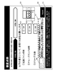
図10及び図11は、実施の形態1に係るアイソレータシステム100の始業前点検における目視点検時の装置点検画面を示す図である。図10に示すように、始業前点検は、目視点検と自動点検からなり、制御ユニット160は、まず先に、作業者が目視で装置の点検を行う目視点検項目をディスプレイ111に表示させる(S106)。目視点検項目の横には、目視点検項目の点検の結果を作業者が入力する確認ボタンB10(目視確認入力部)が表示される。確認ボタンB10は、作業者が入力することで、点検の未完了を示す「NG」の表示から点検の完了を示す「OK」の表示へ切り替わる。また、装置点検画面には、目視点検項目の点検の完了を入力する[Next]ボタンB9が表示される。図11に示すように、[Next]ボタンB9は、目視点検事項が「OK」の表示へ切り替わると、有効となる。[Next]ボタンB9は、目視点検事項が複数ある場合には、複数の確認ボタンB10の全てが「OK」の表示へ切り替わると、有効となる。つまり、作業者は、複数の確認ボタンB10に一つでも「NG」があると[Next]ボタンB9に入力することができず、確認ボタンB10のすべてを「OK」に切り替えることで[Next]ボタンB9へ入力することができる。制御ユニット160は、目視点検画面において確認ボタンB10に一つでも「NG」がある場合には、その画面の表示を維持させる。つまり、制御ユニット160は、目視点検項目が未完了であること又は目視点検項目に異常があることを示す「NG」の確認ボタンB10を含む異常画面を表示させる(S107、S108)。これにより、制御ユニット160は、目視点検項目に異常がある可能性があることを作業者に示唆することができる。一方、作業者によって[Next]ボタンB9への入力がされると、制御ユニット160は、図12に示す次の装置点検画面をディスプレイ111に表示させる(S107、S109)。また、目視点検画面には、目視点検項目がアイソレータシステム100のどこの部分に当たるかを示す案内図A3が表示される。これにより、作業者の作業性を向上することができる。
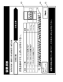
図12~15は、実施の形態1に係るアイソレータシステム100の始業前点検における自動点検時の装置点検画面を示す図である。図12に示すように、制御ユニット160は、始業前点検において、目視点検が完了すると、目視点検項目以外の項目を点検する自動点検を実施する。まず、制御ユニット160は、点検前の準備として、作業者に所定項目を確認させる案内をディスプレイ111に表示させる。制御ユニット160は、所定項目が条件を満たしているかを確認するとともに、同画面に、その所定項目が条件を満たしているかを表示させる。制御ユニット160は、目視点検時の装置点検画面と同様に、所定項目が全ての条件を満たすと有効になる[Next]ボタンB9を表示させる。作業者によって[Next]ボタンB9への入力がされると、制御ユニット160は、図13に示す自動点検時の装置点検画面をディスプレイ111に表示させる(S109)。また、図7には示されていないが、本実施の形態では、作業者によって[Next]ボタンB9への入力がされると、制御ユニット160は、ロック付ハンドル114により前面扉112の開閉をロックする。
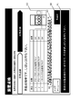
図13に示すように、制御ユニット160は、点検する対象項目及びその対象項目毎の点検結果(点検中であることを示す表示を含む)を表示させる。図14に示すように、制御ユニット160は、目視点検時の装置点検画面と同様、点検対象項目の状態が全て正常になると有効になる[Next]ボタンB9を表示させる。制御ユニット160は、自動点検時の装置点検画面において、点検対象項目の点検結果に一つでも「NG」がある場合には、その画面の表示を維持させる。つまり、制御ユニット160は、点検対象項目に異常があることを示す異常画面を表示させる(S110、S111)。これにより、制御ユニット160は、自動点検項目に異常があることを作業者に示唆することができる。
次に、作業者によって[Next]ボタンB9への入力がされると、制御ユニット160は、メモリ162に「濃度Hiフラグ」が記憶されているか否かを確認する(S112)。
メモリ162に「濃度Hiフラグ」が記憶されていた場合、制御ユニット160は、空調ユニット150に動作開始の信号を送信し、無害化工程を開始させる(S113)。ここで開始される無害化工程は、滅菌処理で行われる無害化工程と同様の工程である。制御ユニット160は、カウンターを有し、所定時間が経過したか否かを測定している(S114)。所定時間が経過したら、制御ユニット160は、図8に示す過酸化水素濃度確認画面と同様の画面をディスプレイ111に表示させる(S115)。作業者によって[YES]ボタンB7を選択されると、制御ユニット160は、空調ユニット150に動作停止の信号を送信し、無害化工程を終了させる(S116)。一方、作業者によって[NO]ボタンB8を選択されると、制御ユニット160は、再度、所定時間の測定を開始する。所定時間が経過したら、再度、過酸化水素濃度確認画面を表示させる(S115)。制御ユニット160は、[YES]ボタンB7が選択されるまで、この動作を繰り返す。無害化工程が終了すると(S116)、制御ユニット160は、ロック付ハンドル114のロックを解除し、始業前点検を終了させる(S117)。
一方、メモリ162に「濃度Hiフラグ」が記憶されていない場合には、制御ユニット160は、ロック付ハンドル114のロックを解除し、始業前点検を終了させる(S117)。
[1-3.効果等]
以上のように、本実施の形態において、アイソレータシステム100は、内部に無菌環境の作業空間A、前面に作業者の腕が挿入される開口113(挿入部)を有する箱状のグローブボックス110(本体ケース)と、過酸化水素(滅菌物質)を供給して作業空間Aを滅菌する滅菌ユニット140(滅菌部)と、作業空間A内を給排気する空調ユニット150(空調部)と、作業者が信号を入力可能なディスプレイ111(表示部)と、滅菌ユニット140、空調ユニット150、及び、ディスプレイ111、に接続された制御ユニット160(制御部)と、を備え、制御ユニット160は、起動後、空調ユニット150を動作させる前に、作業者が目視で動作点検を実施する目視点検事項と作業者が動作点検の完了を入力する図11に示す[Next]ボタンB9(目視確認入力部)とをディスプレイ111に表示させ、[Next]ボタンB9への入力後、空調ユニット150の動作点検を実施し、空調ユニット150の動作点検の状態をディスプレイ111に表示させる。ここで、空調ユニット150の動作点検には、例えば、作業空間Aが気密性を維持されているか確認をするためのリークテストが含まれる。
以上のように、本実施の形態において、アイソレータシステム100は、内部に無菌環境の作業空間A、前面に作業者の腕が挿入される開口113(挿入部)を有する箱状のグローブボックス110(本体ケース)と、過酸化水素(滅菌物質)を供給して作業空間Aを滅菌する滅菌ユニット140(滅菌部)と、作業空間A内を給排気する空調ユニット150(空調部)と、作業者が信号を入力可能なディスプレイ111(表示部)と、滅菌ユニット140、空調ユニット150、及び、ディスプレイ111、に接続された制御ユニット160(制御部)と、を備え、制御ユニット160は、起動後、空調ユニット150を動作させる前に、作業者が目視で動作点検を実施する目視点検事項と作業者が動作点検の完了を入力する図11に示す[Next]ボタンB9(目視確認入力部)とをディスプレイ111に表示させ、[Next]ボタンB9への入力後、空調ユニット150の動作点検を実施し、空調ユニット150の動作点検の状態をディスプレイ111に表示させる。ここで、空調ユニット150の動作点検には、例えば、作業空間Aが気密性を維持されているか確認をするためのリークテストが含まれる。
これにより、作業者の安全性を向上することができるアイソレータシステムを提供できる。例えば異常終了後にアイソレータシステム100を起動した場合であって、グローブボックス110内に滅菌物質が残留しているような場合であっても、目視点検を行ってから、空調ユニット150を動作させることができる。そのため、起動時に滅菌物質が内部に残留している場合でも、確実に装置の点検ができ、作業者の危険を低減することできるアイソレータシステムを提供できる。
一方、起動時に目視点検を行わずに自動点検又は実験環境動作を開始して空調ユニット150を動作させると、何かしらの問題により作業空間Aの気密性が保持されてない場合に、滅菌物質が外部に漏れ、作業者を危険にさらすことになる。例えば、グローブが損傷していたり、前面扉112に亀裂があったりすることが考えられる。
また、本実施の形態において、制御ユニット160は、空調ユニット150の動作点検の結果、問題がないときは、作業者が動作点検の完了を入力する図14に示す[Next]ボタンB9(空調確認入力部)をディスプレイ111に表示させ、問題があるときは、問題を表示した画面を表示部に表示させる(図7のS111)。
これにより、作業者は、目視点検で異常がない場合であっても、空調ユニット150に異常がある場合には空調ユニット150の動作をさせることがない。そのため、作業者の危険を低減することできるアイソレータシステムを提供できる。
また、本実施の形態において、アイソレータシステム100は、グローブボックス110の前面に開閉可能に取り付けられた前面扉112と、制御ユニット160からの信号により前面扉112の開閉を施錠可能なロック付ハンドル114(施錠部)と、を備え、制御ユニット160は、目視点検事項及び図10、11に示す[Next]ボタンB9をディスプレイ111に表示させる際に、作業空間A内の過酸化水素の濃度が所定濃度以下の場合はロック付ハンドル114をロック解除状態とし前面扉112を開閉可能にするが、作業空間A内の過酸化水素の濃度が所定濃度を超える場合はロック付ハンドル114を施錠状態とし前面扉112を開閉不能とする。
これにより、作業空間A内の過酸化水素の濃度が高い場合に、作業者が目視点検を実施するために誤って前面扉112を開けてしまうことがない。そのため、作業者の危険を低減することができるアイソレータシステムを提供できる。
また、本実施の形態において、制御ユニット160(制御システム)は、内部に無菌環境の作業空間A、前面に作業者の腕が挿入される開口113(挿入部)を有する箱状のグローブボックス110(本体ケース)と、過酸化水素(滅菌物質)を供給して作業空間Aを滅菌する滅菌ユニット140(滅菌部)と、作業空間A内を給排気する空調ユニット150(空調部)と、作業者が信号を入力可能なディスプレイ111(表示部)と、を備えアイソレータシステム100を制御する。制御ユニット160は、起動後、空調ユニット150を動作させる前に、作業者が目視で動作点検を実施する目視点検事項と作業者が動作点検の完了を入力する図14に示す[Next]ボタンB9(空調確認入力部)とを表示部に表示させ、[Next]ボタンB9への入力後、空調ユニット150の動作点検を実施し、空調ユニット150の動作点検の状態をディスプレイ111に表示させる。
これにより、例えば異常終了後にアイソレータシステム100を起動した場合であって、グローブボックス110内に滅菌物質が残留しているような場合であっても、目視点検を行ってから、制御ユニット160を動作させることができる。そのため、起動時に滅菌物質が内部に残留している場合でも、確実に装置の点検ができ、作業者の危険を低減することできるアイソレータシステムの制御システムを提供できる。
一方、起動時に目視点検を行わずに自動点検又は実験環境動作を開始して制御ユニット160を動作させると、何かしらの問題により作業空間Aの気密性が保持されてない場合に、滅菌物質が外部に漏れ、作業者を危険にさらすことになる。例えば、グローブが損傷していたり、前面扉112に亀裂があったりすることが考えられる。
また、本実施の形態において、制御ユニット160は、空調ユニット150の動作点検の結果、問題がないときは、作業者が動作点検の完了を入力する図14に示す[Next]ボタンB9(空調確認入力部)をディスプレイ111に表示させ、問題があるときは、問題を表示した画面を表示部に表示させる(図7のS111)。
これにより、作業者は、目視点検で異常がない場合であっても、空調ユニット150に異常がある場合には空調ユニット150の動作をさせることがない。そのため、作業者の危険を低減することできるアイソレータシステムの制御システムを提供できる。
また、本実施の形態において、アイソレータシステム100は、グローブボックス110の前面に開閉可能に取り付けられた前面扉112と、制御ユニット160からの信号により前面扉112の開閉を施錠可能なロック付ハンドル114(施錠部)と、を備え、制御ユニット160は、目視点検事項及び図10、11に示す[Next]ボタンB9をディスプレイ111に表示させる際に、作業空間A内の過酸化水素の濃度が所定濃度以下の場合はロック付ハンドル114をロック解除状態とし前面扉112を開閉可能にするが、作業空間A内の過酸化水素の濃度が所定濃度を超える場合はロック付ハンドル114を施錠状態とし前面扉112を開閉不能とする。
これにより、作業空間A内の過酸化水素の濃度が高い場合に、作業者が目視点検を実施するために誤って前面扉112を開けてしまうことがない。そのため、作業者の危険を低減することができるアイソレータシステムの制御システムを提供できる。
(実施の形態2)
以下、実施の形態2に係るアイソレータシステム101について、図15を用いて説明する。
以下、実施の形態2に係るアイソレータシステム101について、図15を用いて説明する。
[2-1.構成]
アイソレータシステム101の構成は、実施の形態1に係るアイソレータシステム100と同様であるため、ここでは説明を省略する。
アイソレータシステム101の構成は、実施の形態1に係るアイソレータシステム100と同様であるため、ここでは説明を省略する。
[2-2.動作]
実施の形態2に係るアイソレータシステム101の動作について、以下図15を用いて説明する。図15は、実施の形態2に係るアイソレータシステム101の始業前点検を説明するためのフローチャートである。
実施の形態2に係るアイソレータシステム101の動作について、以下図15を用いて説明する。図15は、実施の形態2に係るアイソレータシステム101の始業前点検を説明するためのフローチャートである。
実施の形態1同様、制御ユニット160は、アイソレータシステム101が起動されると、まずディスプレイ111に図6のようなトップメニュー画面を表示させる。作業者は、トップメニュー画面から操作したいメニューを選択し、アイソレータシステム101を動作させる。トップニュー画面には、アイソレータシステム101の動作を終了させる[終了]ボタンB1と、装置の点検を行う[始業前点検]ボタンB2と、滅菌処理等を行う[操作メニュー]ボタンB3と、各種データの設定を行うB4と、作業者の認証を行うB5と、が表示される。
ここでは、装置の点検を行う始業前点検について、基本的に実施の形態1のアイソレータシステム100に類似するため、アイソレータシステム100の動作との違いに重点を置いて説明する。
図15に示すように、制御ユニット160は、始業前点検が選択されると、まず前回の動作終了時が正常な動作で終了したかを確認する(S201)。制御ユニット160は、前回の動作終了時が正常な動作で終了している場合には、図8に示す画面をディスプレイ111に表示させる(S202)。
一方、制御ユニット160は、前回の動作終了時が正常な動作で終了していない場合、つまり前回異常終了時には、前回の動作終了時が異常であることを示す「異常フラグ」をメモリ162に記憶させた後、図9に示す画面をディスプレイ111に表示させる(S203、S204)。
実施の形態2において、次の装置点検工程(S205~S212)は、実施の形態1の装置点検工程(S104~S111)と同様であるため、説明は省略する。
次に、作業者によって図14の[Next]ボタンB9への入力がされると、制御ユニット160は、メモリ162に「濃度Hiフラグ」が記憶されているか否かを確認する(S213)。
メモリ162に「濃度Hiフラグ」が記憶されていた場合、制御ユニット160は、メモリ162に「異常フラグ」が記憶されているか否かを確認する(S214)。その後、空調ユニット150に動作開始の信号を送信し、無害化工程を開始させる(S215、S218)。制御ユニット160は、カウンターを有し、所定時間が経過したか否かを測定する(S216、S219)。このとき、制御ユニット160は、メモリ162に「異常フラグ」が記憶されているときの所定時間を、メモリ162に「異常フラグ」が記憶されていないときの所定時間より長く設定する。所定時間が経過したら、制御ユニット160は、図8に示す過酸化水素濃度確認画面と同様の画面をディスプレイ111に表示させる(S217、S220)。作業者によって[YES]ボタンB7を選択されると、制御ユニット160は、空調ユニット150に動作停止の信号を送信し、無害化工程を終了させる(S221)。一方、作業者によって[NO]ボタンB8を選択されると、制御ユニット160は、再度、所定時間の測定を開始する。所定時間が経過したら、再度、過酸化水素濃度確認画面を表示させる(S216、S219)。制御ユニット160は、[YES]ボタンB7が選択されるまで、この動作を繰り返す。ここで、繰り返す時の所定時間を、1回前の所定時間より短くしてもよい。それにより、無害化工程の時間を短縮することができる。無害化工程が終了すると(S221)、制御ユニット160は、ロック付ハンドル114のロックを解除し、始業前点検を終了させる(S222)。
一方、メモリ162に「濃度Hiフラグ」が記憶されていない場合には、制御ユニット160は、ロック付ハンドル114のロックを解除し、始業前点検を終了させる(S222)。
[2-3.効果等]
以上のように、本実施の形態において、制御ユニット160は、メモリ162に「異常フラグ」が記憶されているときの所定時間を、メモリ162に「異常フラグ」が記憶されていないときの所定時間より長く設定する。
以上のように、本実施の形態において、制御ユニット160は、メモリ162に「異常フラグ」が記憶されているときの所定時間を、メモリ162に「異常フラグ」が記憶されていないときの所定時間より長く設定する。
異常終了後の作業空間A内は、滅菌物質の濃度が高い可能性が高い。実施の形態2に係る制御ユニット160は、その場合に無害化工程の時間を長く設定するため、作業者の安全性をより向上することできる。よって、安全性の高いアイソレータシステム及びその制御システムを提供することができる。
(他の実施の形態)
以上のように、本出願において開示する技術の例示として、実施の形態1~2を説明した。しかしながら、本開示における技術は、これに限定されず、適宜、変更、置き換え、付加、省略などを行った実施の形態にも適用可能である。また、上記実施の形態1~2で説明した各構成要素を組み合わせて、新たな実施の形態とすることも可能である。
以上のように、本出願において開示する技術の例示として、実施の形態1~2を説明した。しかしながら、本開示における技術は、これに限定されず、適宜、変更、置き換え、付加、省略などを行った実施の形態にも適用可能である。また、上記実施の形態1~2で説明した各構成要素を組み合わせて、新たな実施の形態とすることも可能である。
そこで、以下、他の実施の形態を例示する。
実施の形態1~2では、本体ケースの一例としてグローブボックス110を説明した。グローブボックス110は、グローブの点検等、作業者が目視で点検する対象があるため、作業者の安全性を向上させることができる。しかし、本体ケースは、グローブボックス110に限定されない。例えば、パスボックス170に本開示の技術を用いてもよい。また、グローブボックスが連結されたアイソレータシステムにおいて、複数のアイソレータシステムに本開示技術を用いてもよい。また、安全キャビネットやクリーンベンチに本開示の技術を用いてもより。要するに、本体ケースは、作業空間を構成する装置であればよい。
実施の形態1~2では、滅菌部の一例として滅菌ユニット140を説明した。滅菌ユニット140は、ノズルからミスト状の滅菌ミストを噴射する構成であるため、滅菌処理時間の短縮が図れる。しかし、滅菌部は、滅菌ユニット140に限定されない。例えば、滅菌物質をヒータで熱して、ガス化した滅菌ガスを供給するものでもよい。また、超音波振動子を用いて、滅菌物質をミスト化した滅菌ミストを供給するものでもよい。また、一度ミスト化した滅菌ミストをヒータで熱してガス化するものでもよい。要するに、滅菌部は、滅菌物質を作業空間内へ供給し、作業空間内を滅菌できる装置であればよい。
また、実施の形態1~2における無害化工程は、グローブボックス110内に空気を供給するとともにグローブボックス110内の気体を排気して、グローブボックス110内の気体を置換し、作業空間A内の滅菌物質の濃度を低下させている。しかし、無害化工程は、この工程に限定されない。作業空間Aから排気された気体が作業空間Aへ戻る循環経路中に触媒等の滅菌物質低減手段を設け、作業空間A内の気体をその循環経路を循環させる工程にしてもよい。
本実施の形態1~2のアイソレータシステム100、101は、濃度センサーを備えていないため、作業者が検知管も用いて測定し、その結果を入力する構成としているが、本開示技術は、この構成に限られない。例えば、濃度計や濃度センサーを用いてもよい。アイソレータシステム100、101が濃度センサーを備えている場合は、作業者が濃度測定及び結果入力をする必要がないため、制御ユニット160は、図8、9に示す過酸化水素濃度確認画面の表示を省略できる。
実施の形態1~2では、空調部の一例として、空調ユニット150を説明した。空調ユニット150は、給気ユニット150aと排気ユニット150bを有するため、効率よく空調が行える。また、作業空間内の気圧等の環境条件を制御しやすい。しかし、空調部は、空調ユニット150に限定されない。例えば、パスボックス170の空調ユニット180のように、給気ユニットしかないものでもよい。また、排気ユニットしかないものでもよい。また、給気ユニットと排気ユニットの他に、気体を供給できる経路を有するもの、内部の気体を循環することができるものなどであってもよい。要するに、空調部は、作業空間内に気体を供給する、又は、作業空間内の気体を排気することができる装置であればよい。
以上のように、本開示における技術の例示として、実施の形態を説明した。そのために、添付図面および詳細な説明を提供した。
したがって、添付図面および詳細な説明に記載された構成要素の中には、課題解決のために必須な構成要素だけでなく、上記技術を例示するために、課題解決のためには必須でない構成要素も含まれ得る。そのため、それらの必須ではない構成要素が添付図面や詳細な説明に記載されていることをもって、直ちに、それらの必須ではない構成要素が必須であるとの認定をするべきではない。
また、上述の実施の形態は、本開示における技術を例示するためのものであるから、特許請求の範囲またはその均等の範囲において種々の変更、置き換え、付加、省略などを行うことができる。
本開示は、起動時に装置の点検をするアイソレータシステム及びその制御システムに適用可能である。具体的には、再生医療関連及び製薬関連の実験に用いられるアイソレータシステム及びその制御システムなどに、本開示は適用可能である。
100 アイソレータシステム
101 アイソレータシステム
110 グローブボックス
111 ディスプレイ
112 前面扉
113 開口
114 ロック付ハンドル
120 遠心機ユニット
130 観察ユニット
140 滅菌ユニット
141 滅菌液ボトル
142a 吸水管
142b ペリスタポンプ
143 ノズル
144 ノズル
145a コンプレッサ
145b 給気管
146a 切替バルブ
146b 切替バルブ
147a 切替バルブ
147b 切替バルブ
148 電子天秤
149 給気バルブ
150 空調ユニット
150a 給気ユニット
150b 排気ユニット
151 給気口
152 HEPAフィルタ
153 給気ブロワ
155 排気口
156 HEPAフィルタ
157 排気ブロワ
160 制御ユニット(制御部)
162 メモリ(記憶部)
170 パスボックス
180 空調ユニット
183 給気ブロア
191 拡散ファン
192 拡散ファン
200 インキュベータ
B1 [終了]ボタン
B2 [始業前点検]ボタン
B3 [操作メニュー]ボタン
B4 [データ設定]ボタン
B5 [認証]ボタン
B6 [トップニュー]ボタン
B7 [YES]ボタン
B8 [NO]ボタン
B9 [Next]ボタン
B10 確認ボタン
A1 操作説明欄
A2 注意事項欄
A3 案内図
101 アイソレータシステム
110 グローブボックス
111 ディスプレイ
112 前面扉
113 開口
114 ロック付ハンドル
120 遠心機ユニット
130 観察ユニット
140 滅菌ユニット
141 滅菌液ボトル
142a 吸水管
142b ペリスタポンプ
143 ノズル
144 ノズル
145a コンプレッサ
145b 給気管
146a 切替バルブ
146b 切替バルブ
147a 切替バルブ
147b 切替バルブ
148 電子天秤
149 給気バルブ
150 空調ユニット
150a 給気ユニット
150b 排気ユニット
151 給気口
152 HEPAフィルタ
153 給気ブロワ
155 排気口
156 HEPAフィルタ
157 排気ブロワ
160 制御ユニット(制御部)
162 メモリ(記憶部)
170 パスボックス
180 空調ユニット
183 給気ブロア
191 拡散ファン
192 拡散ファン
200 インキュベータ
B1 [終了]ボタン
B2 [始業前点検]ボタン
B3 [操作メニュー]ボタン
B4 [データ設定]ボタン
B5 [認証]ボタン
B6 [トップニュー]ボタン
B7 [YES]ボタン
B8 [NO]ボタン
B9 [Next]ボタン
B10 確認ボタン
A1 操作説明欄
A2 注意事項欄
A3 案内図
Claims (6)
- 内部に無菌環境で作業を行うための作業空間、前面に作業者の腕が挿入される挿入部を有する箱状の本体ケースと、
滅菌物質を供給して前記作業空間を滅菌する滅菌部と、
前記作業空間内を給排気する空調部と、
作業者が信号を入力可能な表示部と、
前記滅菌部、前記空調部、及び、前記表示部に接続された制御部と、を備え、
前記制御部は、起動後、前記空調部を動作させる前に、作業者が目視で点検を実施する目視点検事項と作業者が目視での点検の完了を入力する目視確認入力部とを前記表示部に表示させ、前記目視確認入力部への入力後、前記空調部の動作点検を実施し、前記空調部の動作点検の状態を前記表示部に表示させる、
アイソレータシステム。 - 前記制御部は、前記空調部の動作点検の結果、問題がないときは、作業者が前記空調部の動作点検の完了を入力する空調確認入力部を前記表示部に表示させ、問題があるときは、問題を表示した画面を前記表示部に表示させる、
請求項1に記載のアイソレータシステム。 - 前記本体ケースの前面に開閉可能に取り付けられた前面扉と、
前記制御部からの信号により前記前面扉の開閉を施錠可能な施錠部と、をさらに備え、
前記制御部は、前記目視点検事項及び前記目視確認入力部を前記表示部に表示させる際に、前記作業空間内の前記滅菌物質の濃度が所定濃度以下の場合は前記施錠部をロック解除状態とし前記前面扉を開閉可能にするが、前記作業空間内の前記滅菌物質の濃度が所定濃度を超える場合は前記施錠部を施錠状態とし前記前面扉を開閉不能とする、
請求項1又は2に記載のアイソレータシステム。 - 内部に無菌環境で作業を行うための作業空間、前面に作業者の腕が挿入される挿入部を有する箱状の本体ケースと、滅菌物質を供給して前記作業空間を滅菌する滅菌部と、前記作業空間内を給排気する空調部と、作業者が信号を入力可能な表示部と、を備える作業用チャンバーを制御する制御システムであって、
前記制御システムは、起動後、前記空調部を動作させる前に、作業者が目視で点検を実施する目視点検事項と作業者が目視での点検の完了を入力する目視確認入力部とを前記表示部に表示させ、前記目視確認入力部への入力後、前記空調部の動作点検を実施し、前記空調部の動作点検の状態を前記表示部に表示させる、
制御システム。 - 前記制御システムは、前記空調部の動作点検の結果、問題がないときは、作業者が前記空調部の動作点検の完了を入力する空調確認入力部を前記表示部に表示させ、問題があるときは、問題を表示した画面を前記表示部に表示させる、
請求項4に記載の制御システム。 - 前記作業用チャンバーは、前記本体ケースの前面に開閉可能に取り付けられた前面扉と、前記制御部からの信号により前記前面扉の開閉を施錠可能な施錠部と、をさらに備え、
前記制御システムは、前記目視点検事項及び前記目視確認入力部を前記表示部に表示させる際に、前記作業空間内の前記滅菌物質の濃度が所定濃度以下の場合は前記施錠部をロック解除状態とし前記前面扉を開閉可能にするが、前記作業空間内の前記滅菌物質の濃度が所定濃度を超える場合は前記施錠部を施錠状態とし前記前面扉を開閉不能とする、
請求項4又は5に記載の制御システム。
Applications Claiming Priority (2)
| Application Number | Priority Date | Filing Date | Title |
|---|---|---|---|
| JP2013-179041 | 2013-08-30 | ||
| JP2013179041 | 2013-08-30 |
Publications (1)
| Publication Number | Publication Date |
|---|---|
| WO2015029413A1 true WO2015029413A1 (ja) | 2015-03-05 |
Family
ID=52586003
Family Applications (1)
| Application Number | Title | Priority Date | Filing Date |
|---|---|---|---|
| PCT/JP2014/004357 Ceased WO2015029413A1 (ja) | 2013-08-30 | 2014-08-25 | アイソレータシステム及びその制御システム |
Country Status (1)
| Country | Link |
|---|---|
| WO (1) | WO2015029413A1 (ja) |
Cited By (4)
| Publication number | Priority date | Publication date | Assignee | Title |
|---|---|---|---|---|
| JP5873608B2 (ja) * | 2013-08-30 | 2016-03-01 | パナソニックヘルスケアホールディングス株式会社 | アイソレータシステム及びその制御システム |
| JPWO2016159226A1 (ja) * | 2015-03-31 | 2018-02-01 | 学校法人獨協学園獨協医科大学 | クリーンベンチ機能付きインキュベータおよびインキュベータシステム |
| WO2018021553A1 (ja) * | 2016-07-28 | 2018-02-01 | 北海道公立大学法人札幌医科大学 | アイソレータ |
| JP2019071797A (ja) * | 2017-10-12 | 2019-05-16 | 株式会社日立産機システム | 安全キャビネット及びクリーンベンチ |
Citations (3)
| Publication number | Priority date | Publication date | Assignee | Title |
|---|---|---|---|---|
| JP2003226500A (ja) * | 2002-02-06 | 2003-08-12 | Nippon Yusoki Co Ltd | 作業車両の情報表示装置 |
| JP2010069255A (ja) * | 2008-09-22 | 2010-04-02 | Sanyo Electric Co Ltd | アイソレータ |
| JP2010154793A (ja) * | 2008-12-26 | 2010-07-15 | Sanyo Electric Co Ltd | Co2インキュベータ |
-
2014
- 2014-08-25 WO PCT/JP2014/004357 patent/WO2015029413A1/ja not_active Ceased
Patent Citations (3)
| Publication number | Priority date | Publication date | Assignee | Title |
|---|---|---|---|---|
| JP2003226500A (ja) * | 2002-02-06 | 2003-08-12 | Nippon Yusoki Co Ltd | 作業車両の情報表示装置 |
| JP2010069255A (ja) * | 2008-09-22 | 2010-04-02 | Sanyo Electric Co Ltd | アイソレータ |
| JP2010154793A (ja) * | 2008-12-26 | 2010-07-15 | Sanyo Electric Co Ltd | Co2インキュベータ |
Non-Patent Citations (2)
| Title |
|---|
| ATSUSHI NAKAO: "Cell Processing Isolator ni yoru GMP Kanri no Koritsuka", BIO. CLIN., vol. 23, no. 9, 2008, pages 833 - 839 * |
| ATSUSHI NAKAO: "CPC Un'yo no Kansoka to Cost Down no Ichi Shuho: Isolator", SAIBO PROCESSING KONWAKAI HOMEPAGE, 2006, Retrieved from the Internet <URL:http://www.kuhp.kyoto-u.ac.jp/-cpf/files/nakao.pdf> [retrieved on 20141105] * |
Cited By (5)
| Publication number | Priority date | Publication date | Assignee | Title |
|---|---|---|---|---|
| JP5873608B2 (ja) * | 2013-08-30 | 2016-03-01 | パナソニックヘルスケアホールディングス株式会社 | アイソレータシステム及びその制御システム |
| JPWO2016159226A1 (ja) * | 2015-03-31 | 2018-02-01 | 学校法人獨協学園獨協医科大学 | クリーンベンチ機能付きインキュベータおよびインキュベータシステム |
| WO2018021553A1 (ja) * | 2016-07-28 | 2018-02-01 | 北海道公立大学法人札幌医科大学 | アイソレータ |
| JPWO2018021553A1 (ja) * | 2016-07-28 | 2019-05-23 | 北海道公立大学法人 札幌医科大学 | アイソレータ |
| JP2019071797A (ja) * | 2017-10-12 | 2019-05-16 | 株式会社日立産機システム | 安全キャビネット及びクリーンベンチ |
Similar Documents
| Publication | Publication Date | Title |
|---|---|---|
| JP4300863B2 (ja) | 無菌システムとその使用方法 | |
| ES2731662T3 (es) | Método y aparato para la descontaminación de tuberías | |
| EP3165283B1 (en) | Safety cabinet | |
| JP5873608B2 (ja) | アイソレータシステム及びその制御システム | |
| JP6872615B2 (ja) | 安全キャビネットおよびその滅菌方法 | |
| JP6271224B2 (ja) | インキュベータおよびインキュベータの除染方法 | |
| AU2015231409B2 (en) | Saturation-enhanced, low-concentration vaporized hydrogen peroxide decontamination method | |
| WO2015029413A1 (ja) | アイソレータシステム及びその制御システム | |
| EP2889045B1 (en) | Isolator system | |
| EP2692848A1 (en) | Decontamination solution spray device | |
| JP2007259715A (ja) | 培養装置 | |
| RU2683644C2 (ru) | Аппарат и способ анализа биологических индикаторов | |
| CN105196313A (zh) | 一种双面层流操作的无菌检查工艺隔离器 | |
| JP7027239B2 (ja) | 滅菌ガス浄化閉鎖系装置 | |
| US10980904B2 (en) | Aeration method of isolator system | |
| US11112143B2 (en) | Fan filter unit, sterilization apparatus and clean room | |
| JP5209415B2 (ja) | Co2インキュベータのオゾン滅菌方法 | |
| CN109469362A (zh) | 一种实验室 | |
| JP4773986B2 (ja) | オゾンガス殺菌装置 | |
| JP6444741B2 (ja) | アイソレータシステム | |
| CN109602937A (zh) | 一种灭杀封闭环境中病原微生物的方法 | |
| JP2012228276A (ja) | Co2インキュベータのオゾン滅菌装置 | |
| JPH03275150A (ja) | 清浄作業台 | |
| CN209637302U (zh) | 一种实验室 | |
| CN217566866U (zh) | 一种灭菌设备及灭菌系统 |
Legal Events
| Date | Code | Title | Description |
|---|---|---|---|
| 121 | Ep: the epo has been informed by wipo that ep was designated in this application |
Ref document number: 14839201 Country of ref document: EP Kind code of ref document: A1 |
|
| DPE1 | Request for preliminary examination filed after expiration of 19th month from priority date (pct application filed from 20040101) | ||
| NENP | Non-entry into the national phase |
Ref country code: DE |
|
| 122 | Ep: pct application non-entry in european phase |
Ref document number: 14839201 Country of ref document: EP Kind code of ref document: A1 |
|
| NENP | Non-entry into the national phase |
Ref country code: JP |