WO2015025653A1 - 回転電機および回転電機の製造方法 - Google Patents
回転電機および回転電機の製造方法 Download PDFInfo
- Publication number
- WO2015025653A1 WO2015025653A1 PCT/JP2014/069098 JP2014069098W WO2015025653A1 WO 2015025653 A1 WO2015025653 A1 WO 2015025653A1 JP 2014069098 W JP2014069098 W JP 2014069098W WO 2015025653 A1 WO2015025653 A1 WO 2015025653A1
- Authority
- WO
- WIPO (PCT)
- Prior art keywords
- terminal portion
- rotating electrical
- insulating layer
- electrical machine
- terminal
- Prior art date
- Legal status (The legal status is an assumption and is not a legal conclusion. Google has not performed a legal analysis and makes no representation as to the accuracy of the status listed.)
- Ceased
Links
Images





Classifications
-
- H—ELECTRICITY
- H02—GENERATION; CONVERSION OR DISTRIBUTION OF ELECTRIC POWER
- H02K—DYNAMO-ELECTRIC MACHINES
- H02K3/00—Details of windings
- H02K3/46—Fastening of windings on the stator or rotor structure
- H02K3/52—Fastening salient pole windings or connections thereto
- H02K3/521—Fastening salient pole windings or connections thereto applicable to stators only
- H02K3/522—Fastening salient pole windings or connections thereto applicable to stators only for generally annular cores with salient poles
-
- H—ELECTRICITY
- H02—GENERATION; CONVERSION OR DISTRIBUTION OF ELECTRIC POWER
- H02K—DYNAMO-ELECTRIC MACHINES
- H02K15/00—Processes or apparatus specially adapted for manufacturing, assembling, maintaining or repairing of dynamo-electric machines
- H02K15/30—Manufacture of winding connections
- H02K15/33—Connecting winding sections; Forming leads; Connecting leads to terminals
-
- H—ELECTRICITY
- H02—GENERATION; CONVERSION OR DISTRIBUTION OF ELECTRIC POWER
- H02K—DYNAMO-ELECTRIC MACHINES
- H02K2203/00—Specific aspects not provided for in the other groups of this subclass relating to the windings
- H02K2203/09—Machines characterised by wiring elements other than wires, e.g. bus rings, for connecting the winding terminations
Definitions
- the present invention relates to a rotating electrical machine and a method for manufacturing the rotating electrical machine.
- Patent Document 1 a rotating electrical machine having a stator in which a plurality of divided cores are arranged in a cylindrical shape is known (see Patent Document 1).
- a conductive wire coated with an insulating layer is wound around the split core, and a terminal portion of the conductive wire is connected to a connection conductor such as a connection ring.
- Patent Document 1 describes a technique for connecting a terminal portion (coil lead wire) of a conductive wire and a terminal portion (connection terminal) of a connecting conductor by a fusing method.
- a terminal portion of a conductive wire is inserted into an insertion portion of a terminal portion of a connecting conductor, and the insertion portion is crimped and crimped by an electrode, and a contact portion and a terminal formed in the insertion portion
- the insulating layer softened at the terminal portion is pushed out into the groove portion by heat during energization, and the conductor of the terminal portion and the contact portion are electrically connected.
- Patent Document 1 The fusing method described in Patent Document 1 has a problem that it is difficult to reduce the number of manufacturing steps because a predetermined cooling time is required because the terminal portion of the conducting wire becomes high temperature.
- a rotating electrical machine including a plurality of conductive wires coated with an insulating layer constituting a stator coil, and a connecting conductor for connecting the conductive wires to each other via a terminal portion, includes a plurality of conductive wires.
- Terminal portions connected to the terminal portions are provided at both ends of each of the terminals, and one surface of the terminal portion is a conductive wire bonding surface bonded to the terminal portion, and a surface opposite to the conductive wire bonding surface in the terminal portion. Is provided with an insulating layer, and the terminal portion is provided with a joint projection to be joined to the terminal portion.
- a method of manufacturing a rotating electrical machine including a plurality of conductive wires coated with an insulating layer constituting a stator coil, and a connecting conductor for connecting the conductive wires to each other through a terminal portion
- a connecting projection is formed on the terminal portion of the connecting conductor by pressing, the terminal portion of the conducting wire is brought into contact with the connecting projection through the insulating layer, and the terminal portion and the terminal portion of the connecting conductor are connected to the anvil. It sandwiches and presses with a horn, gives a high frequency vibration from the horn, removes the insulating layer covered by the terminal part, and joins the terminal part and the terminal part.
- the removal of the insulating layer of the conducting wire and the joining of the conducting wire and the connecting conductor can be performed in one step, and the generation of heat can be suppressed at the time of joining, thereby reducing the number of manufacturing steps. be able to.
- FIG. 2 is a schematic sectional view taken along line II-II in FIG. 1.
- FIG. 3A is a perspective view showing a split core to which a bobbin is attached
- FIG. 3B is a perspective view showing a state where a stator coil is attached to the bobbin.
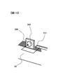
- the elements on larger scale which expanded the A section of FIG. The figure which shows typically a mode that a terminal part and a coil terminal part are ultrasonically joined in the rotary electric machine which concerns on a comparative example.
- the perspective view which shows the terminal part and coil terminal part in the rotary electric machine which concern on the 1st Embodiment of this invention.
- FIG. 8 is a schematic cross-sectional view taken along line VIII-VIII in FIG. 7.
- the perspective view which shows the terminal part and coil terminal part in the rotary electric machine which concern on the 2nd Embodiment of this invention.
- FIG. 14 is a schematic side cross-sectional view showing a state where the coil terminal portion and the terminal portion of FIG.
- the rotating electrical machine according to the present invention can be applied to, for example, a pure electric vehicle that runs only by the rotating electrical machine, or a hybrid electric vehicle that is driven by both the engine and the rotating electrical machine.
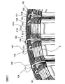
- FIG. 1 is a half sectional view showing a rotating electrical machine 100.
- FIG. 1 schematically shows a cross section cut along a plane parallel to the rotation center axis CL of the rotor 2 and including the rotation center axis CL.
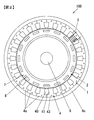
- FIG. 2 is a schematic sectional view taken along the line II-II in FIG.
- the rotating electrical machine 100 operates as an electric motor or a generator, and includes a rotor 2, a stator 1, and a housing 9 that holds the rotor 2 and the stator 1.
- the rotor 2 is rotatably arranged inside the cylindrical stator 1.
- the rotor 2 includes a cylindrical rotor core 7 and a permanent magnet 6.
- a cylindrical shaft 8 is press-fitted into the hollow portion of the rotor core 7, and the rotor core 7 is fixed to the shaft 8.
- permanent magnets 6 are arranged at equal intervals along the circumferential direction.
- the permanent magnet 6 acts as a field pole of the rotor 2 and has a 16-pole configuration in the present embodiment.
- the housing 9 includes a cylindrical center bracket 9c and a pair of end brackets 9a and 9b attached so as to close the openings at both ends of the center bracket 9c.
- One end bracket 9a is provided with a bearing 11a
- the other end bracket 9b is provided with a bearing 11b.
- the stator 1 is held by a center bracket 9c
- the shaft 8 of the rotor 2 is rotatably held by bearings 11a and 11b provided on the end brackets 9a and 9b, respectively.
- the stator 1 includes a substantially cylindrical stator core 4, U-phase, V-phase, and W-phase windings, and a connection member (see FIG. 3).
- the stator core 4 is composed of 24 divided cores 4 a, and the 24 divided cores 4 a are arranged in the circumferential direction to have a cylindrical shape.
- the stator core 4 is divided into 24 divided cores 4a in the circumferential direction.
- the split core 4a is formed, for example, by stacking a plurality of core plates formed by punching a magnetic steel sheet having a thickness of about 0.05 to 1.0 mm by press working.
- Each of the split cores 4a has a core back 43 and teeth 41 protruding radially inward from the core back 43.
- the split core 4a is formed in a T shape in plan view so as to partition one slot 40 between a pair of split cores 4a adjacent in the circumferential direction.
- a plurality of slots 40 and teeth 41 are formed at equal intervals in the circumferential direction on the inner peripheral side of the stator core 4 that is a split core assembly.
- the U-phase winding, V-phase winding and W-phase winding are each formed by electrically connecting a plurality of stator coils 5.
- the stator coil 5 is formed by winding an insulation-coated conductive wire (hereinafter simply referred to as an insulation wire) around the teeth 41 of each divided core 4 a constituting the stator core 4.
- an insulation wire hereinafter simply referred to as an insulation wire
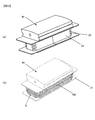
- FIG. 3 (a) is a perspective view showing the split core 4a to which the bobbin 21 is attached
- FIG. 3 (b) is a perspective view showing a state in which the stator coil 5 is attached to the bobbin 21.
- FIG. A resin bobbin 21 is attached to the teeth 41 of the split core 4a as shown in FIG. 3A, and the insulation wire 105 constituting the stator coil 5 is attached to the bobbin 21 as shown in FIG. It is wound intensively.
- grooves 22 are provided at the corners of the four corners of the bobbin 21 to prevent the insulation wire 105 that is a flat wire from being disturbed.
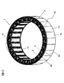
- FIG. 4 is a perspective view showing the stator 1, and FIG. 5 is a partially enlarged view of an A portion of FIG.
- the connection member 60 includes connection rings 61U, 61V, 61W corresponding to the U phase, the V phase, and the W phase, a connection ring 61N that forms a neutral point of the star connection, and connection rings 61U, 61V, 61W, 61N. And an insulating support member 62 that supports the substrate in an insulated state.
- the connection member 60 is provided on one end side of the stator core 4 in the axial direction, and is disposed on a back yoke formed by connecting the core backs 43 of the divided cores 4a.
- connection rings 61U, 61V, 61W are annular and have a terminal portion 106 connected to the coil terminal portion 151 of the insulating wire 105 constituting the stator coil 5.
- the connection rings 61U, 61V, 61W have different diameters and are arranged concentrically.
- eight terminal portions 106 are provided in each of the connection rings 61U, 61V, 61W corresponding to each phase, and 24 terminal portions 106 are provided in the connection ring 61N constituting the neutral point.
- the terminal portion 106 is a flat plate-like member protruding in the axial direction of the connection rings 61U, 61V, 61W, 61N, and has a width of about 10 mm and a thickness of about 1 mm.
- Each of the plurality of stator coils 5 constituting the U-phase winding has one end connected to the connection ring 61U and the other end connected to the connection ring 61N.
- Each of the plurality of stator coils 5 constituting the V-phase winding has one end connected to the connection ring 61V and the other end connected to the connection ring 61N.
- Each of the plurality of stator coils 5 constituting the W-phase winding has one end connected to the connection ring 61W and the other end connected to the connection ring 61N.
- the plurality of insulated wires 105 constituting the stator coil 5 are electrically connected by the connection rings 61U, 61V, 61W, 61N via the terminal portion 106.
- each lead wire is bent along the circumferential direction and is a coil terminal portion 151 that is joined to the terminal portion 106.
- the coil terminal portion 151 of each stator coil 5 and the terminal portion 106 of each connection ring 61U, 61V, 61W, 61N are overlapped along the radial direction of the rotating electrical machine 100 and are ultrasonically bonded. Be joined.
- connection structure and the joining method of the terminal part 106 of each connection ring 61U, 61V, 61W, 61N and the coil terminal part 151 are the same, hereinafter, the terminal part 106 of the connection ring 61N and the coil terminal part 151 are the same.
- the connection structure and the joining method are described as a representative, and the description of the connection structure and the joining method between the terminal portions 106 of the connection rings 61U, 61V, 61W corresponding to the respective phases and the coil terminal portion 151 is omitted.
- the insulating layer peeling operation of the coil terminal portion 151, the one surface of the conductor 153 of the coil terminal portion 151, and the terminal portion are not performed separately.
- the number of manufacturing steps is reduced by performing the joining operation with one surface of 106 in one step.
- the one surface of the conductor 153 of the coil terminal portion 151 is referred to as a conductive wire bonding surface 153a
- the one surface of the terminal portion 106 is referred to as a conductor bonding surface 161.
- FIG. 6 is a diagram schematically illustrating a state in which the terminal portion 906 and the coil terminal portion 151 are ultrasonically bonded, and is a diagram illustrating a comparative example of the present embodiment.
- the conductor joint surface 961 that joins the coil terminal portion 151 is a flat surface having no unevenness.
- the insulated wire 105 is a flat wire, and the cross-sectional shape of the conductor 153 of the coil terminal portion 151 is rectangular.
- the long side dimension of the conductor 153 is about 1.9 mm, the short side dimension is about 1.1 mm, and the corners of the conductor 153 are rounded.
- the outer surface of the conductor 153 is covered with an insulating layer 152 having a thickness of about 0.05 mm.
- the conductor 153 has a pair of long side surfaces (hereinafter referred to as wide side surfaces) and a pair of short side surfaces (hereinafter referred to as narrow side surfaces), and has a wide side surface and a narrow width constituting the outer peripheral surface.
- the side surfaces are covered with an insulating layer 152.
- the coil terminal portion 151 is in contact with the terminal portion 906 through the insulating layer 152 at one wide side surface that is the conductive wire bonding surface 153a.
- the coil terminal portion 151 and the terminal portion 906 are sandwiched between the anvil WA and the horn WH, and high-frequency vibration in the v direction is applied from the horn WH in a state where pressure is applied.
- the conductor bonding surface 906 is a flat surface as in the comparative example, a sufficient frictional force between the terminal portion 906 and the insulating layer 152 cannot be obtained.
- the insulating layer 152 in the vicinity of the center of the coil terminal portion 151 is not easily pushed outward. For this reason, in the comparative example, it is difficult to peel off the insulating layer 152, and it may take time to perform the solid phase bonding, or may not be bonded.
- the joint convex portion 165 is provided in the terminal portion 106 so that the insulating layer 152 can be easily peeled off.
- FIG. 7 is a perspective view showing the terminal portion 106 and the coil terminal portion 151 in the rotary electric machine 100 according to the first embodiment of the present invention
- FIG. 8 is a schematic cross-sectional view taken along the line VIII-VIII in FIG. It is.
- the joint projection 165 is composed of a plurality of protrusions 166 arranged in a matrix. Note that the height dimension of the protrusion 166 is exaggerated for convenience of explanation.
- a lattice-shaped groove 167 is formed on one surface of the terminal portion 106 by being pressed and plastically deformed by a knurling tool (not shown).
- the crossing angle between the grooves 167 is a right angle.
- a rectangular portion surrounded by the groove 167 is formed as a protrusion 166 rising from the bottom of the groove 167, and as shown in FIG. 8A, the top surface of the protrusion 166 serves as a conductor bonding surface 161 via the insulating layer 152. In contact with the coil terminal 151.
- the frictional force increases at the contact interface during ultrasonic bonding, and the peeling of the insulating layer 152 is promoted.
- the conductor 153 of the coil terminal portion 151 and the terminal portion 106 are solid-phase bonded.
- FIG. 9 is a diagram for explaining a process of manufacturing the rotating electrical machine 100.
- the method of manufacturing the rotating electrical machine 100 includes a preparation step S100, a stator assembly step S110, a coil connection step S120, and a rotor assembly step S130.
- each component constituting the rotating electrical machine 100 for example, the center bracket 9c, the end brackets 9a and 9b, the split core 4a, the rotor 2, and the like are prepared.
- a permanent magnet 6 is mounted in advance on the rotor core 7 of the rotor 2, and a shaft 8 is press-fitted into the hollow portion of the rotor core 7 and integrated.
- a bobbin 21 is attached to the split core 4a, and an insulating wire 105 is wound around the bobbin 21 to form a stator coil 5.
- stator assembling step S110 the stator core 4 is fixed to the center bracket 9c by shrink fitting.
- the stator core 4 in which the divided cores 4a are assembled in a cylindrical shape is arranged, and the center bracket 9c that has been heated in advance and expanded in inner diameter by thermal expansion is fitted into the stator core 4 that is a divided core assembly.
- the center bracket 9c By cooling the center bracket 9c and contracting the inner diameter, the outer periphery of the stator core 4 is tightened by the thermal contraction.
- the inner diameter dimension of the center bracket 9c is set smaller than the outer diameter dimension of the stator core 4 so that the stator core 4 does not idle with respect to the center bracket 9c due to the reaction caused by the torque of the rotor 2 during operation.
- the stator core 4 is firmly fixed in the center bracket 9c.
- the stator core 4 is not limited to being fixed by shrink fitting, but may be fixed to the center bracket 9c by press fitting.
- the coil connection step S120 includes a pressing step S121, a positioning step S123, a narrow pressure step S125, and a vibration step S127.
- a knurled tool (not shown) is pressed against one surface of the terminal portion 106, that is, the terminal portion 106 is plastically deformed by pressing, thereby forming a lattice-like groove 167 (FIG. 7).
- the portion surrounded by the groove 167 is formed as a protrusion 166 rising from the bottom of the groove 167, and the joint protrusion 165 is formed by the plurality of protrusions 166 arranged in a matrix (see FIG. 7).
- the depth of the groove 167 that is, the height of the protrusion 166 is about 0.1 mm.
- the conductive wire bonding surface 153a which is one wide side surface of the coil terminal portion 151 of the insulating wire 105 and the conductor bonding surface 161 of the terminal portion 106 are connected to the insulating layer 152. Positioning so as to contact with each other.
- the coil terminal portion 151 and the terminal portion 106 are disposed so as to overlap along the radial direction of the rotating electrical machine 100 (see FIG. 5).
- the horn WH is vibrated in the v direction, which is substantially perpendicular to the pressurizing direction, and high frequency vibration is applied from the horn WH to the coil terminal 151.
- the insulating layer 152 is broken and peeled off by the frictional force between the insulating convex layer 165 and the insulating layer 152 covered by the conductive wire bonding surface 153a of the conductor 153 of the coil terminal 151.
- the peeled fine insulating layer 152 is discharged from the outside in the short direction of the coil terminal portion 151.
- High-frequency vibration is continuously applied from the horn WH to the coil terminal 151 from the state in which the conductor joining surface 153a of the conductor 153 and the conductor joining surface 161 are in direct contact with each other.
- the contact interface between the conductor bonding surface 153a and the conductor bonding surface 161 is heated by frictional heat, and atomic motion is activated.
- movement of metal atoms due to diffusion occurs, an attractive force is generated between the metal atoms, and the conductor 153 of the coil terminal portion 151 and the terminal portion 106 are solid-phase bonded.
- the insulating layer 152 between the conductor 153 and the terminal portion 106 is peeled off, but the outer peripheral surface of the conductor 153 excluding the conductor joint surface 153a, such as a surface opposite to the conductor joint surface 153a in the coil terminal portion 151. Insulating layer 152 remains.
- the shaft 8 is mounted on the bearing 11a of one end bracket 9a.
- the end bracket 9a is fixed to the center bracket 9c by closing the opening on one end side of the center bracket 9c with one end bracket 9a so that the rotor 2 is arranged inside the stator 1.
- the opening on the other end side of the center bracket 9c is closed with the other end bracket 9b, and the end bracket 9b is fixed to the center bracket 9c.
- the joint convex portion 165 is formed on one surface of the terminal portion 106 of the connection rings 61U, 61V, 61W, 61N by press working. Thereafter, the conductive wire bonding surface 153 a of the coil terminal portion 151 of the insulating wire 105 is brought into contact with the bonding convex portion 165 via the insulating layer 152. The coil terminal portion 151 and the terminal portion 106 are sandwiched between the anvil WA and the horn WH and pressurized. In this state, high-frequency vibration is applied from the horn WH, and the insulating layer coated on the conductive wire bonding surface 153a of the coil terminal portion 151 The coil terminal portion 151 and the terminal portion 106 are solid-phase bonded.
- the insulating layer 152 is peeled to expose the surface of the conductor 153 of the coil terminal portion 151, and the exposed surface of the conductor 153 and the terminal portion 106 are solid-phase bonded. Can do. That is, it is not necessary to peel off the insulating layer 152 in advance, and the peeling of the insulating layer 152 and solid phase bonding can be realized in one step, and the number of manufacturing steps can be reduced. Furthermore, since the ultrasonic bonding method is employed in this embodiment, heat generation can be suppressed during bonding.
- the terminal portion 106 is provided with a joint protrusion 165.
- the joint convex portion 165 includes a plurality of protrusions 166 arranged in a matrix, and can increase the coefficient of friction. For this reason, the frictional force between the insulating layer 152 covered with the coil terminal portion 151 and the terminal portion 106 can be improved as compared with the comparative example (see FIG. 6). As a result, destruction and peeling of the insulating layer 152 are promoted during ultrasonic bonding, and the insulating layer 152 can be removed in a shorter time than the comparative example (see FIG. 6).
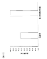
- FIG. 10 is a graph showing the insulating layer removal time in the comparative example and the insulating layer removal time in the first embodiment of the present invention.
- the insulating layer removal time refers to the time from when the horn WH is vibrated until the insulating layer 152 between the conductor 153 of the coil terminal portion 151 and the terminal portion 106 is removed.
- the insulating layer removal time is set such that the horn WH is pressed against the coil terminal 151 with a constant force (for example, 0.5 MPa), the high frequency vibration is applied by the horn WH, and then the horn WH is applied. Is a time required to move toward the terminal portion 106 by a predetermined distance from the origin (for example, 0.6 mm long enough for the thickness of the insulating layer 152 of 0.05 mm).
- test members of the terminal portions 106 and 906 used in the experiment have dimensions of about 10 mm in width and about 1 mm in thickness.
- the test member of the coil terminal 151 used in the experiment has a long side dimension of the conductor 153 of about 1.9 mm and a short side dimension of about 1.1 mm, and the corners of the conductor 153 are rounded. ing.
- the insulation layer removal time was measured by performing ultrasonic bonding on the test member of the terminal portion 906 and the test member of the coil terminal portion 151 of the comparative example in which the bonding convex portion is not provided. The experiment was performed several tens of times.
- the average insulation layer removal time in the comparative example was 2.1 seconds.
- the insulating member is removed by ultrasonic bonding the test member of the terminal portion 106 of the first embodiment provided with the joint protrusion 165 and the test member of the coil terminal portion 151 by the same number of experiments as in the comparative example. Time was measured. As a result, the average value of the insulating layer removal time in the first embodiment was 0.76 seconds. That is, in the first embodiment, it was confirmed that the insulating layer removal time was about 1/3 of that of the comparative example, and the insulating layer 152 could be removed in a shorter time than that of the comparative example.
- the bonding convex portion 165 includes the plurality of protrusions 166 arranged in a matrix and can increase the coefficient of friction. Therefore, the insulating layer 152 covered by the coil terminal portion 151, The frictional force with the terminal portion 106 can be improved as compared with the comparative example (see FIG. 6). As a result, the destruction and peeling of the insulating layer 152 are promoted at the time of ultrasonic bonding, and the insulation sandwiched between the conductor 153 of the coil terminal portion 151 and the terminal portion 106 as compared with the comparative example (see FIG. 6). The layer 152 can be more reliably removed, and the conductor 153 and the terminal portion 106 can be solid-phase bonded.
- FIG. 11 is a graph showing the joining success rate in the comparative example and the joining success rate of the first embodiment of the present invention.
- the joining success rate is the ratio of the number of successes to the number of experiments.
- the success means that the insulating layer 152 between the conductor 153 of the coil terminal portion 151 and the terminal portion 106 is sufficiently removed, and the conductor 153 and the terminal portion 106 are solid-phase bonded.
- the failure is that the conductor 153 and the terminal portion 106 were not solid-phase bonded due to insufficient removal of the insulating layer 152.
- the state where the horn WH is pressed against the coil terminal 151 with a constant force (for example, 0.5 MPa) is used as the origin, and after applying high-frequency vibration by the horn WH, the horn WH is a predetermined distance from the origin.
- test members of the terminal portions 106 and 906 used in the experiment have dimensions of about 10 mm in width and about 1 mm in thickness.
- the test member of the coil terminal 151 used in the experiment has a long side dimension of the conductor 153 of about 1.9 mm and a short side dimension of about 1.1 mm, and the corners of the conductor 153 are rounded. ing.
- the test member of the terminal portion 106 of the first embodiment provided with the joint convex portion 165 and the test member of the coil terminal portion 151 are ultrasonically joined the same number of experiments as in the comparative example, and the number of successes. The number of failures was measured.
- the joining success rate (success count) / (success count + failure count) ⁇ 100 in the first embodiment is 100%. That is, in the first embodiment, it was confirmed that the bonding success rate was higher than that of the comparative example, and the reliability of the solid phase bonding was improved.
- the coil terminal portion 151 and the terminal portion 106 are arranged so as to overlap along the radial direction of the rotating electrical machine 100. For this reason, at the time of ultrasonic joining, since sufficient arrangement space of anvil WA and horn WH can be ensured, workability
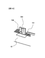
- FIG. 12 is a view corresponding to FIG. 7 of the first embodiment, and is a perspective view showing the terminal portion 206 and the coil terminal portion 151 in the rotating electrical machine according to the second embodiment of the present invention.
- the rotating electrical machine of the second embodiment is different from the first embodiment in that the connecting convex portion 265 which is a portion solid-phase bonded to the conductor 153 of the coil terminal portion 151 is used.
- the point is that the shape is wavy.
- the joint convex portion 265 includes a plurality of mountain-shaped protrusions 266 that extend in parallel to each other.
- the manufacturing method of the rotating electrical machine according to the second embodiment is different from the first embodiment in that a pressing tool (not shown) provided with a plurality of pressing protrusions extending in parallel with each other is provided in the pressing process.
- a pressing tool (not shown) provided with a plurality of pressing protrusions extending in parallel with each other is provided in the pressing process.
- the joint convex portion 265 is formed by pressing the terminal portion 206 against one surface and plastically deforming the terminal portion 206.
- the horn WH is vibrated in a direction substantially perpendicular to the pressurizing direction.
- the horn WH is substantially perpendicular to the pressurizing direction, and is substantially orthogonal to the extending direction of the protrusion 266.
- the horn WH is vibrated in the v2 direction.
- FIGS. A third embodiment will be described with reference to FIGS.
- the same or corresponding parts as those in the first embodiment are denoted by the same reference numerals, and description thereof is omitted.
- differences from the first embodiment will be described in detail.
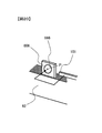
- FIG. 13 is a view corresponding to FIG. 7 of the first embodiment, and is a perspective view showing the terminal portion 306 and the coil terminal portion 151 in the rotating electrical machine according to the third embodiment.
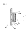
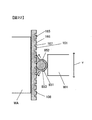
- 14 is a diagram corresponding to FIG. 8A of the first embodiment, and is a schematic side sectional view showing a state where the coil terminal portion 151 and the terminal portion 306 of FIG. 13 are in contact with each other.
- the rotating electrical machine of the third embodiment is different from the first embodiment in that the bonding convexity is a portion that is solid-phase bonded to the conductor 153 of the coil terminal portion 151 as shown in FIG. 13 and FIG.
- the shape of the part is a single protrusion 366.
- the protrusion 366 as the joint convex portion has a substantially partial spherical shape with a diameter of about 7 mm and a protruding height from the flat portion of about 0.5 mm, and has a curved surface that inclines outward from the top. .
- the manufacturing method of the rotating electrical machine according to the third embodiment is different from the first embodiment in that a pressing tool (not shown) having a curved tip is used as one surface of the terminal portion 306 in the pressing process.
- a pressing tool (not shown) having a curved tip is used as one surface of the terminal portion 306 in the pressing process.
- the terminal portion 306 is plastically deformed by being pressed to form a curved projection 366 as a joint convex portion.
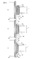
- FIG. 15 is a diagram illustrating a state in which the insulating layer 152 is peeled off and the coil terminal unit 151 and the terminal unit 306 are solid-phase bonded at the time of ultrasonic bonding between the coil terminal unit 151 and the terminal unit 306. .
- the positioning step as shown in FIG. 15A, positioning is performed so that the conductive wire bonding surface 153 a of the coil terminal portion 151 and the top of the protrusion 366 are brought into contact with each other via the insulating layer 152.
- the clamping step the coil terminal portion 151 and the terminal portion 106 are sandwiched between the anvil WA and the horn WH and pressurized.
- the horn WH is vibrated in a direction substantially perpendicular to the pressurizing direction, and high-frequency vibration is applied from the horn WH to the coil terminal portion 151.
- the insulating layer 152 is caused by the frictional force between the insulating layer 152 and the projection 366 that are covered by the conductive wire bonding surface 153 a of the coil terminal portion 151. Is destroyed and peeled off.
- the broken and peeled insulating layer 152 is discharged outward along the inclined surface from the gap between the coil terminal portion 151 and the protrusion 366 as schematically indicated by the arrow B.
- the softened insulating layer 152 is pushed outward along the inclined surface from the gap between the coil terminal portion 151 and the protrusion 366.
- the terminal portion 306 is provided with a single protrusion 366 as a bonding convex portion.
- the protrusion 366 is configured to incline outward from the top, and when the top is brought into contact with the coil terminal portion 151, a gap is formed around the top and is broken and peeled off during ultrasonic bonding.
- the insulating layer 152 and the softened insulating layer 152 can be easily extruded along the inclined surface. As a result, the insulating layer 152 can be removed by ultrasonic bonding in a shorter time than the comparative example (see FIG. 6).
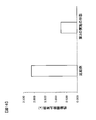
- FIG. 16 is a graph showing the insulating layer removal time in the comparative example and the insulating layer removal time in the third embodiment of the present invention.
- the insulation layer removal time was measured by performing ultrasonic bonding on the test member of the terminal portion 906 and the test member of the coil terminal portion 151 of the comparative example in which the bonding convex portion is not provided. The experiment was performed several tens of times. The average insulation layer removal time in the comparative example was 2.1 seconds.
- the test member of the terminal portion 306 and the test member of the coil terminal portion 151 according to the third embodiment provided with the projection 366 as the joint convex portion and the test member of the coil terminal portion 151 are ultrasonically joined the same number of times as the comparative example.
- the insulation layer removal time was measured.
- the average value of the insulating layer removal time in the third embodiment was 0.75 seconds. That is, in the third embodiment, it has been confirmed that the insulating layer removal time is about 1/3 compared to the comparative example, and the insulating layer 152 can be removed in a shorter time than the comparative example.
- the projection 366 as the joint convex portion is configured to be inclined outward from the top, and when the top of the projection 366 is brought into contact with the coil terminal portion 151, A gap is formed around the top. For this reason, the softened insulating layer 152 can be extruded along the inclined surface, or the peeled insulating layer 152 can be smoothly removed along the inclined surface. Therefore, as compared with the comparative example (see FIG. 6), the insulating layer 152 sandwiched between the conductor 153 of the coil terminal portion 151 and the terminal portion 306 is more reliably removed, and the conductor 153 and the terminal portion 306 are removed. Can be solid-phase bonded.
- FIG. 17 is a graph showing the joining success rate in the comparative example and the joining success rate of the third embodiment.
- the test member of the terminal portion 306 and the test member of the coil terminal portion 151 according to the third embodiment provided with the projection 366 as the joint convex portion and the test member of the coil terminal portion 151 are ultrasonically joined the same number of times as the comparative example. The number of successes and failures was measured.
- the joining success rate (success count) / (success count + failure count) ⁇ 100 in the third embodiment is 100%. That is, in the third embodiment, it was confirmed that the bonding success rate was higher than that of the comparative example, and the reliability of the solid phase bonding was improved.
- the protrusion 366 has a substantially partial spherical shape, but the shape of the protrusion 366 is not limited to this.
- the joining convex part should just be comprised with the single euros
- FIG. the third embodiment may be modified as follows. (1) As shown in FIG. 18, in place of the substantially partial spherical projection 366 provided on the terminal portion 306 in FIG. 13, a partial cylindrical projection 466 cut along the rotation center axis of the rotating electrical machine is provided. The terminal part 406 may be joined to the coil terminal part 151. (2) As shown in FIG.
- the V-shaped projection 566 extending along the rotation center axis of the rotating electrical machine.
- the terminal portion 506 provided with a terminal may be joined to the coil terminal portion 151.
- a terminal portion 606 provided with a conical protrusion 666 having a vertex P instead of the substantially partial spherical protrusion 366 provided in the terminal portion 306 of FIG. 151 may be joined.
- a terminal portion 706 provided with a quadrangular pyramid-shaped projection 766 is joined to the coil terminal portion 151 in place of the substantially partial spherical projection 366 provided in the terminal portion 306 of FIG. You may make it make it.
- the terminal portion 706 may be provided with a projection having another polygonal pyramid shape such as a triangular pyramid shape or a pentagonal pyramid shape without being limited to the quadrangular pyramid shape.
- the terminal portion 106 in which the intersecting angle between the grooves 167 is a right angle and the rectangular protrusions 166 are arranged in a matrix has been described, but the present invention is not limited to this.
- a terminal portion in which rhombus-shaped protrusions are arranged in a matrix with the crossing angle between grooves as an acute angle or an obtuse angle may be formed.
- the example in which the horn WH is brought into contact with the coil terminal portions 151 and 851 and the anvil WA is brought into contact with the terminal portions 106, 206, 306, 406, 506, 606, and 706 has been described.
- the anvil WA may be brought into contact with the coil terminal portions 151 and 851
- the horn WH may be brought into contact with the terminal portions 106, 206, 306, 406, 506, 606, and 706 to perform ultrasonic bonding.
- the present invention may be applied to rotating electric machines mounted on other electric vehicles such as railway vehicles such as hybrid trains, passenger cars such as buses, cargo vehicles such as trucks, industrial vehicles such as battery-type forklift trucks, and the like.
- the present invention is not limited to the above-described embodiments, and other forms conceivable within the scope of the technical idea of the present invention are also included in the scope of the present invention. .
Landscapes
- Engineering & Computer Science (AREA)
- Power Engineering (AREA)
- Manufacturing & Machinery (AREA)
- Manufacture Of Motors, Generators (AREA)
- Windings For Motors And Generators (AREA)
Abstract
回転電機は、ステータコイルを構成する絶縁層が被覆された複数の導線、ならびに、導線同士を端子部を介して接続する接続用導体を備えた回転電機であって、複数の導線のそれぞれの両端には、端子部に接続された端末部が設けられ、端末部の一の面は、端子部に接合された導線接合面とされ、端末部における導線接合面の反対側の面には絶縁層が設けられ、端子部には、端末部に接合される接合凸部が設けられている。
Description
本発明は、回転電機および回転電機の製造方法に関する。
従来、複数の分割コアが円筒状に配置されてなるステータを備えた回転電機が知られている(特許文献1参照)。分割コアには、絶縁層が被覆された導線が巻回され、導線の端末部が結線リングなどの接続用導体に接続される。
特許文献1には、ヒュージング工法により導線の端末部(コイル引出し線)と接続用導体の端子部(接続端子)とを接続する技術が記載されている。特許文献1に記載のステータの製造方法では、導線の端末部を接続用導体の端子部の挿通部に挿通し、挿通部を電極によって圧着通電かしめし、挿通部に形成された接触部と端末部とを接触させ、さらに通電時の熱で端末部の軟化した絶縁層を溝部に押し出し、端末部の導電体と接触部とを電気的に接続する。
特許文献1に記載のヒュージング工法では、導線の端末部が高温になるため、所定の冷却時間が必要になり、製造工数の低減が難しいという問題があった。
本発明の第1の態様によると、ステータコイルを構成する絶縁層が被覆された複数の導線、ならびに、導線同士を端子部を介して接続する接続用導体を備えた回転電機は、複数の導線のそれぞれの両端には、端子部に接続された端末部が設けられ、端末部の一の面は、端子部に接合された導線接合面とされ、端末部における導線接合面の反対側の面には絶縁層が設けられ、端子部には、端末部に接合される接合凸部が設けられている。
本発明の第6の態様によると、ステータコイルを構成する絶縁層が被覆された複数の導線、ならびに、導線同士を端子部を介して接続する接続用導体を備えた回転電機の製造方法は、接続用導体の端子部に、プレス加工によって接合凸部を形成し、導線の端末部を絶縁層を介して接合凸部に当接させ、端末部と接続用導体の端子部とを、アンビルとホーンとで挟み、加圧し、ホーンから高周波振動を与えて、端末部に被覆された絶縁層を除去し、端末部と端子部とを接合する。
本発明の第6の態様によると、ステータコイルを構成する絶縁層が被覆された複数の導線、ならびに、導線同士を端子部を介して接続する接続用導体を備えた回転電機の製造方法は、接続用導体の端子部に、プレス加工によって接合凸部を形成し、導線の端末部を絶縁層を介して接合凸部に当接させ、端末部と接続用導体の端子部とを、アンビルとホーンとで挟み、加圧し、ホーンから高周波振動を与えて、端末部に被覆された絶縁層を除去し、端末部と端子部とを接合する。
本発明によれば、導線の絶縁層の除去と、導線と接続用導体との接合とを一工程で行うことができるとともに、接合時に熱の発生を抑えることができるため、製造工数を低減することができる。
以下、図面を参照して本発明の実施の形態について説明する。
本発明による回転電機は、たとえば回転電機のみによって走行する純粋な電気自動車や、エンジンと回転電機の双方によって駆動されるハイブリッド型の電気自動車に適用できる。
本発明による回転電機は、たとえば回転電機のみによって走行する純粋な電気自動車や、エンジンと回転電機の双方によって駆動されるハイブリッド型の電気自動車に適用できる。
-第1の実施の形態-
図1は、回転電機100を示す半断面図である。図1は、ロータ2の回転中心軸CLに平行な平面であって、回転中心軸CLを含む平面で切断した断面を模式的に示している。なお、図1では、説明の便宜上、各構成を概念的に示している。図2は図1のII-II線で切断した断面模式図である。回転電機100は、電動機または発電機として作動するものであり、ロータ2と、ステータ1と、ロータ2およびステータ1を保持するハウジング9とを有している。
図1は、回転電機100を示す半断面図である。図1は、ロータ2の回転中心軸CLに平行な平面であって、回転中心軸CLを含む平面で切断した断面を模式的に示している。なお、図1では、説明の便宜上、各構成を概念的に示している。図2は図1のII-II線で切断した断面模式図である。回転電機100は、電動機または発電機として作動するものであり、ロータ2と、ステータ1と、ロータ2およびステータ1を保持するハウジング9とを有している。
ロータ2は、円筒形状のステータ1の内側において、回転可能に配設されている。ロータ2は、円筒形状のロータコア7と、永久磁石6とを備えている。ロータコア7の中空部には円柱状のシャフト8が圧入され、ロータコア7がシャフト8に固定されている。ロータコア7の外周近傍には、永久磁石6が周方向に沿って等間隔に配設されている。永久磁石6はロータ2の界磁極として作用し、本実施の形態では16極構成となっている。3相交流電流がステータコイル5に流されると、回転磁界がステータ1に発生し、この回転磁界がロータ2の永久磁石6に作用してトルクが生じる。
ハウジング9は、円筒状のセンターブラケット9cと、センターブラケット9cの両端の開口を塞ぐように取り付けられた一対のエンドブラケット9a,9bとを備えている。一方のエンドブラケット9aには軸受11aが設けられ、他方のエンドブラケット9bには軸受11bが設けられている。ステータ1はセンターブラケット9cにより保持され、ロータ2のシャフト8はエンドブラケット9a,9bのそれぞれに設けられた軸受11a,11bにより回転自在に保持されている。
ステータ1は、略円筒形状のステータコア4と、U相、V相、W相巻線と、結線用部材(図3参照)とを備えている。図2に示すように、ステータコア4は、24個の分割コア4aで構成され、24個の分割コア4aが周方向に配設されることで円筒形状を呈している。換言すれば、ステータコア4は周方向に24個の分割コア4aに分割されている。分割コア4aは、たとえば、厚さ0.05~1.0mm程度の電磁鋼板をプレス加工により打ち抜いて形成されたコアプレートを複数枚積層して形成されている。
分割コア4aの各々は、コアバック43と、コアバック43から径方向内側に突出するティース41とを有している。分割コア4aは、周方向で隣接する一対の分割コア4aとの間で1つのスロット40を区画するように平面視T字状に形成されている。分割コア組立体であるステータコア4の内周側には、複数のスロット40とティース41とが周方向に等間隔となるように形成されている。
U相巻線、V相巻線およびW相巻線は、それぞれが複数のステータコイル5が電気的に接続されてなる。ステータコイル5は、ステータコア4を構成する各分割コア4aのティース41に、絶縁被覆導線(以下、単に絶縁線と記す)を巻き回すことにより形成される。なお、図2では、便宜上、ステータコイル5が一の分割コア4aに装着されている状態を模式的に示しているが、実際には、ステータコイル5は、各分割コア4aに装着されている(図4参照)。
図3(a)はボビン21が取り付けられた分割コア4aを示す斜視図であり、図3(b)はボビン21にステータコイル5が装着された状態を示す斜視図である。分割コア4aのティース41には、図3(a)に示すように樹脂製のボビン21が取り付けられ、図3(b)に示すように、ステータコイル5を構成する絶縁線105がボビン21に集中的に巻回されている。図3(a)に示すように、ボビン21の四隅の角部には、平角線である絶縁線105の巻乱れを防ぐ溝22が設けられている。
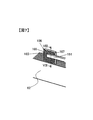
図4はステータ1を示す斜視図であり、図5は図4のA部を拡大した部分拡大図である。結線用部材60は、U相、V相、W相に対応した結線リング61U,61V,61Wと、スター結線の中性点を構成する結線リング61Nと、結線リング61U,61V,61W,61Nを絶縁した状態で支持する絶縁支持部材62とを備えている。結線用部材60は、ステータコア4の軸方向一端側に設けられ、各分割コア4aのコアバック43が連結されてなるバックヨーク上に配置されている。
結線リング61U,61V,61Wは、円環状で、ステータコイル5を構成する絶縁線105のコイル端末部151に接続される端子部106を有している。結線リング61U,61V,61Wは、それぞれ、径が異なり、同心円状に配置されている。本実施の形態では、各相に対応する結線リング61U,61V,61Wのそれぞれに8箇所の端子部106が設けられ、中性点を構成する結線リング61Nに24箇所の端子部106が設けられている。端子部106は、結線リング61U,61V,61W,61Nの軸方向に向けて突出した平板状部材であり、幅が約10mm、厚さが約1mmとされている。
U相巻線を構成する複数のステータコイル5は、それぞれ、一端が結線リング61Uに接続され、他端が結線リング61Nに接続されている。V相巻線を構成する複数のステータコイル5は、それぞれ、一端が結線リング61Vに接続され、他端が結線リング61Nに接続されている。W相巻線を構成する複数のステータコイル5は、それぞれ、一端が結線リング61Wに接続され、他端が結線リング61Nに接続されている。このようにして、ステータコイル5を構成する複数の絶縁線105同士が端子部106を介して、結線リング61U,61V,61W,61Nにより電気的に接続されている。
図5に示すように、分割コア4aに対するステータコイル5の巻き始め引出し線、および、巻終わり引出し線は、結線用部材60に向かって引き出されている。各引出し線の先端部は、周方向に沿うように屈曲され、端子部106と接合されるコイル端末部151とされている。本実施の形態では、各ステータコイル5のコイル端末部151と、各結線リング61U,61V,61W,61Nの端子部106とが、回転電機100の径方向に沿って重ねられ、超音波接合により接合される。
各結線リング61U,61V,61W,61Nの端子部106と、コイル端末部151との接続構造および接合方法は、同様であるため、以下では、結線リング61Nの端子部106と、コイル端末部151との接続構造および接合方法を代表して説明し、各相に対応する結線リング61U,61V,61Wの端子部106と、コイル端末部151との接続構造および接合方法についての説明は省略する。
本実施の形態では、コイル端末部151の絶縁層の剥離作業を個別に行わずに、コイル端末部151の絶縁層の剥離作業と、コイル端末部151の導電体153の一の面と端子部106の一の面との接合作業とを一工程で行うことで製造工数を低減している。以下、コイル端末部151の導電体153における上記一の面を導線接合面153aと記し、端子部106における上記一の面を導体接合面161と記す。
図6は、端子部906とコイル端末部151とが超音波接合される様子を模式的に示す図であり、本実施の形態の比較例を示す図である。比較例では端子部906の形状のみが本実施の形態の端子部106と異なっている。端子部906は、コイル端末部151と接合する導体接合面961が凹凸の無い平面とされている。絶縁線105は平角線であり、コイル端末部151の導電体153の断面形状は矩形状である。導電体153の長辺寸法は約1.9mm、短辺寸法は約1.1mmとされ、導電体153の角部にはR面取りが施されている。導電体153の外周表面には、厚さ0.05mm程度の絶縁層152が被覆されている。導電体153は、一対の長辺側側面(以下、幅広側面と記す)と一対の短辺側側面(以下、幅狭側面と記す)とを有し、外周表面を構成する幅広側面と幅狭側面とが絶縁層152で覆われている。
コイル端末部151は、導線接合面153aである一の幅広側面が絶縁層152を介して端子部906に当接される。超音波接合では、アンビルWAとホーンWHとで、コイル端末部151と端子部906とを挟み、圧力を付与した状態でホーンWHからv方向の高周波振動を与える。しかしながら、比較例のように、導体接合面906が平面である場合、端子部906と絶縁層152との間の摩擦力を十分に得ることができない。さらに、コイル端末部151の中心付近の絶縁層152が外方に押し出されにくい。このため、比較例では、絶縁層152の剥離が難しく、固相接合させる作業に時間がかかったり、接合ができない場合がある。
そこで、本実施の形態では、端子部106に接合凸部165を設け、絶縁層152の剥離が容易に行われるようにした。
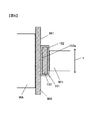
図7は本発明の第1の実施の形態に係る回転電機100における端子部106とコイル端末部151とを示す斜視図であり、図8は図7のVIII-VIII線で切断した断面模式図である。図7および図8に示すように、第1の実施の形態では、接合凸部165がマトリクス状に配列された複数の突起166で構成されている。なお、突起166の高さ寸法は、説明の便宜上、誇張して図示している。
端子部106の一の面には、ローレット工具(不図示)が押し当てられて塑性変形されることにより、格子状の溝167が形成される。溝167同士の交差角度は直角とされている。その結果、溝167によって囲まれる矩形部分が、溝167の底部から立ち上がる突起166として形成され、図8(a)に示すように、突起166の頂面が導体接合面161として絶縁層152を介してコイル端末部151と当接する。第1の実施の形態では、このような複数の突起166が絶縁層152に接触されるため、超音波接合の際に、接触界面において摩擦力が上昇し、絶縁層152の剥離が促進され、図8(b)に示すように、コイル端末部151の導電体153と端子部106とが固相接合される。
回転電機100の製造方法について説明する。図9は、回転電機100を製造する工程を説明するための図である。回転電機100の製造方法は、図9(a)に示すように、準備工程S100と、ステータ組み付け工程S110と、コイル接続工程S120と、ロータ組み付け工程S130とを含む。
-準備工程-
準備工程S100では、回転電機100を構成する各部品、たとえばセンターブラケット9c、エンドブラケット9a,9b、分割コア4a、ロータ2等を準備する。ロータ2のロータコア7には、予め永久磁石6が装着され、シャフト8がロータコア7の中空部に圧入されて一体となっている。なお、分割コア4aには、ボビン21が装着され、ボビン21には絶縁線105が巻回されてステータコイル5が形成されている。
準備工程S100では、回転電機100を構成する各部品、たとえばセンターブラケット9c、エンドブラケット9a,9b、分割コア4a、ロータ2等を準備する。ロータ2のロータコア7には、予め永久磁石6が装着され、シャフト8がロータコア7の中空部に圧入されて一体となっている。なお、分割コア4aには、ボビン21が装着され、ボビン21には絶縁線105が巻回されてステータコイル5が形成されている。
-ステータ組み付け工程-
ステータ組み付け工程S110では、ステータコア4を焼き嵌めによりセンターブラケット9cに固定する。分割コア4aを円筒状に組立てたステータコア4を配置しておき、分割コア組立体であるステータコア4に対して、予め加熱して熱膨張により内径を広げておいたセンターブラケット9cを嵌め込む。センターブラケット9cを冷却して内径を収縮させることで、その熱収縮によりステータコア4の外周部を締め付ける。
ステータ組み付け工程S110では、ステータコア4を焼き嵌めによりセンターブラケット9cに固定する。分割コア4aを円筒状に組立てたステータコア4を配置しておき、分割コア組立体であるステータコア4に対して、予め加熱して熱膨張により内径を広げておいたセンターブラケット9cを嵌め込む。センターブラケット9cを冷却して内径を収縮させることで、その熱収縮によりステータコア4の外周部を締め付ける。
運転時におけるロータ2のトルクによる反作用によって、センターブラケット9cに対してステータコア4が空転しないように、センターブラケット9cの内径寸法は、ステータコア4の外径寸法よりも所定値だけ小さく設定され、焼き嵌めによりステータコア4がセンターブラケット9c内に強固に固定されるようになっている。なお、ステータコア4は焼き嵌めにより固定する場合に限定されることなく、圧入によりセンターブラケット9cに固定することとしてもよい。
-コイル接続工程-
コイル接続工程S120では、ステータコイル5の引出し線の先端部に設けられたコイル端末部151と、結線リング61U,61V,61W,61Nの端子部106とを超音波接合により電気的、機械的に接続する。コイル接続工程S120は、図9(b)に示すように、プレス加工工程S121と、位置決め工程S123と、狭圧工程S125と、振動工程S127とを含む。
コイル接続工程S120では、ステータコイル5の引出し線の先端部に設けられたコイル端末部151と、結線リング61U,61V,61W,61Nの端子部106とを超音波接合により電気的、機械的に接続する。コイル接続工程S120は、図9(b)に示すように、プレス加工工程S121と、位置決め工程S123と、狭圧工程S125と、振動工程S127とを含む。
-プレス加工工程-
プレス加工工程S121では、ローレット工具(不図示)を端子部106の一の面に押し当てて、すなわちプレスすることで端子部106を塑性変形させることにより、格子状の溝167を形成する(図7参照)。その結果、溝167によって囲まれる部分が、溝167の底部から立ち上がる突起166として形成され、マトリクス状に配列された複数の突起166により接合凸部165が形成される(図7参照)。本実施の形態では、溝167の深さ、すなわち突起166の高さを、約0.1mmとした。
プレス加工工程S121では、ローレット工具(不図示)を端子部106の一の面に押し当てて、すなわちプレスすることで端子部106を塑性変形させることにより、格子状の溝167を形成する(図7参照)。その結果、溝167によって囲まれる部分が、溝167の底部から立ち上がる突起166として形成され、マトリクス状に配列された複数の突起166により接合凸部165が形成される(図7参照)。本実施の形態では、溝167の深さ、すなわち突起166の高さを、約0.1mmとした。
-位置決め工程-
位置決め工程S123では、図8(a)に示すように、絶縁線105のコイル端末部151の一の幅広側面である導線接合面153aと、端子部106の導体接合面161とを絶縁層152を介して当接させるように位置決めを行う。コイル端末部151と端子部106とは回転電機100の径方向に沿って重ねて配置する(図5参照)。
位置決め工程S123では、図8(a)に示すように、絶縁線105のコイル端末部151の一の幅広側面である導線接合面153aと、端子部106の導体接合面161とを絶縁層152を介して当接させるように位置決めを行う。コイル端末部151と端子部106とは回転電機100の径方向に沿って重ねて配置する(図5参照)。
-挟圧工程-
挟圧工程S125では、図8(a)に示すように、絶縁線105のコイル端末部151と端子部106とを、回転電機100の径方向外側と内側から、アンビルWAとホーンWHとで挟み、加圧する。
挟圧工程S125では、図8(a)に示すように、絶縁線105のコイル端末部151と端子部106とを、回転電機100の径方向外側と内側から、アンビルWAとホーンWHとで挟み、加圧する。
-振動工程-
振動工程S127では、図8(a)に示すように、ホーンWHを加圧方向に対して略垂直方向であるv方向に振動させ、ホーンWHからコイル端末部151に高周波振動を与える。これにより、コイル端末部151の導電体153における導線接合面153aに被覆された絶縁層152と、接合凸部165との間の摩擦力により、絶縁層152が破壊、剥離される。剥離された細かい絶縁層152は、コイル端末部151の短手方向外方から排出される。導線接合面153aに被覆された絶縁層152が除去されると、図8(b)に示すように、コイル端末部151の導電体153の導線接合面153aと導体接合面161とが直接に接触される。
振動工程S127では、図8(a)に示すように、ホーンWHを加圧方向に対して略垂直方向であるv方向に振動させ、ホーンWHからコイル端末部151に高周波振動を与える。これにより、コイル端末部151の導電体153における導線接合面153aに被覆された絶縁層152と、接合凸部165との間の摩擦力により、絶縁層152が破壊、剥離される。剥離された細かい絶縁層152は、コイル端末部151の短手方向外方から排出される。導線接合面153aに被覆された絶縁層152が除去されると、図8(b)に示すように、コイル端末部151の導電体153の導線接合面153aと導体接合面161とが直接に接触される。
導電体153の導線接合面153aと導体接合面161とが直接に接触した状態から、続けてホーンWHからコイル端末部151に高周波振動を与える。導線接合面153aと導体接合面161との接触界面が、摩擦熱により加熱され、原子運動が活性化される。その結果、拡散による金属原子の移動が発生し、金属原子相互間に引力が生じ、コイル端末部151の導電体153と端子部106とが固相接合される。
なお、導電体153と端子部106との間の絶縁層152は剥離されるが、コイル端末部151における導線接合面153aの反対側の面など、導線接合面153aを除く導電体153の外周表面には絶縁層152が残されている。
-ロータ組み付け工程-
図9(a)に示すロータ組み付け工程S130では、シャフト8を一方のエンドブラケット9aの軸受け11aに装着する。ロータ2をステータ1の内側に配置させるように、一方のエンドブラケット9aによりセンターブラケット9cの一端側の開口を塞いで、エンドブラケット9aをセンターブラケット9cに固着させる。センターブラケット9cの他端側の開口を他方のエンドブラケット9bによって塞いで、エンドブラケット9bをセンターブラケット9cに固着させる。以上で、回転電機100が完成する。
図9(a)に示すロータ組み付け工程S130では、シャフト8を一方のエンドブラケット9aの軸受け11aに装着する。ロータ2をステータ1の内側に配置させるように、一方のエンドブラケット9aによりセンターブラケット9cの一端側の開口を塞いで、エンドブラケット9aをセンターブラケット9cに固着させる。センターブラケット9cの他端側の開口を他方のエンドブラケット9bによって塞いで、エンドブラケット9bをセンターブラケット9cに固着させる。以上で、回転電機100が完成する。
このように、本実施の形態に係る回転電機100の製造方法は、結線リング61U,61V,61W,61Nの端子部106の一の面に、プレス加工によって接合凸部165を形成する。その後、絶縁線105のコイル端末部151の導線接合面153aを絶縁層152を介して接合凸部165に当接させる。コイル端末部151と端子部106とを、アンビルWAとホーンWHとで挟み、加圧し、その状態でホーンWHから高周波振動を与えて、コイル端末部151の導線接合面153aに被覆された絶縁層152を除去し、コイル端末部151と端子部106とを固相接合する。
上述した第1の実施の形態によれば、次の作用効果が得られる。
(1)超音波接合の際に、絶縁層152を剥離させてコイル端末部151の導電体153の表面を露出させ、露出された導電体153の表面と端子部106とを固相接合させることができる。つまり、絶縁層152を予め剥離しておく必要がなく、一工程で絶縁層152の剥離と、固相接合とを実現することができ、製造工数の低減を図ることができる。さらに、本実施の形態では超音波接合法を採用したので、接合時に熱の発生を抑えることができる。ヒュージング工法の際に発生する熱により絶縁層を軟化させ、溝部に押し出す特許文献1に記載の技術(以下、従来技術と記す)で必要となる冷却時間に比べて、本実施の形態では冷却時間が短くて済むため、従来技術に比べて、製造工数の低減を図ることができる。
(1)超音波接合の際に、絶縁層152を剥離させてコイル端末部151の導電体153の表面を露出させ、露出された導電体153の表面と端子部106とを固相接合させることができる。つまり、絶縁層152を予め剥離しておく必要がなく、一工程で絶縁層152の剥離と、固相接合とを実現することができ、製造工数の低減を図ることができる。さらに、本実施の形態では超音波接合法を採用したので、接合時に熱の発生を抑えることができる。ヒュージング工法の際に発生する熱により絶縁層を軟化させ、溝部に押し出す特許文献1に記載の技術(以下、従来技術と記す)で必要となる冷却時間に比べて、本実施の形態では冷却時間が短くて済むため、従来技術に比べて、製造工数の低減を図ることができる。
(2)端子部106には、接合凸部165が設けられている。接合凸部165は、マトリクス状に配列された複数の突起166で構成され、摩擦係数を高めることができる。このため、コイル端末部151に被覆される絶縁層152と、端子部106との間の摩擦力を比較例(図6参照)に比べて向上させることができる。その結果、超音波接合の際に、絶縁層152の破壊、剥離が促進され、絶縁層152の除去を比較例(図6参照)に比べて短い時間で行うことができる。
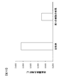
比較例(図6参照)において超音波接合した際の絶縁層除去時間と、第1の実施の形態(図8参照)において超音波接合した際の絶縁層除去時間とを実験により比較検証した。図10は、比較例での絶縁層除去時間と、本発明の第1の実施の形態の絶縁層除去時間とを示すグラフである。絶縁層除去時間とは、ホーンWHを振動させてから、コイル端末部151の導電体153と端子部106との間の絶縁層152が除去されるまでの時間のことを指す。なお、実験では、絶縁層除去時間を、ホーンWHを一定の力(たとえば、0.5MPa)でコイル端末部151に加圧した状態を原点とし、ホーンWHにより高周波振動を与えてから、ホーンWHが原点から所定の距離(たとえば、絶縁層152の厚み0.05mmに対して十分に長い0.6mm)だけ端子部106側に移動するまでの時間とした。
実験で用いた端子部106,906の試験部材は、幅が約10mm、厚さが約1mmの寸法を有している。実験で用いたコイル端末部151の試験部材は、導電体153の長辺寸法が約1.9mm、短辺寸法が約1.1mmであり、導電体153の角部にはR面取りが施されている。
接合凸部が設けられていない比較例の端子部906の試験部材と、コイル端末部151の試験部材とに対して、超音波接合を行って絶縁層除去時間を測定した。実験は数十回行った。比較例での絶縁層除去時間の平均値は2.1秒となった。接合凸部165が設けられた第1の実施の形態の端子部106の試験部材と、コイル端末部151の試験部材とを、比較例と同じ実験回数だけ、超音波接合を行って絶縁層除去時間を測定した。その結果、第1の実施の形態での絶縁層除去時間の平均値は0.76秒となった。つまり、第1の実施の形態では、絶縁層除去時間が比較例に比べて1/3程度となり、比較例に比べて短い時間で絶縁層152を除去できることが確認された。
(3)上記したように、接合凸部165は、マトリクス状に配列された複数の突起166で構成され、摩擦係数を高めることができるため、コイル端末部151に被覆される絶縁層152と、端子部106との間の摩擦力を比較例(図6参照)に比べて向上させることができる。その結果、超音波接合の際に、絶縁層152の破壊、剥離が促進され、比較例(図6参照)に比べて、コイル端末部151の導電体153と、端子部106とによって挟まれる絶縁層152を、より確実に除去し、導電体153と端子部106とを固相接合させることができる。
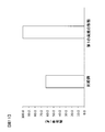
比較例(図6参照)において超音波接合した際の接合成功率と、第1の実施の形態(図8参照)において超音波接合した際の接合成功率とを実験により比較検証した。図11は、比較例での接合成功率と、本発明の第1の実施の形態の接合成功率とを示すグラフである。接合成功率とは、実験回数に対する成功回数の割合である。
なお、成功とは、コイル端末部151の導電体153と端子部106との間の絶縁層152が十分に除去され、導電体153と端子部106とが固相接合されたことである。これに対して失敗とは、絶縁層152の除去が不十分であることに起因して導電体153と端子部106とが固相接合されなかったことである。なお、実験では、ホーンWHを一定の力(たとえば、0.5MPa)でコイル端末部151に加圧した状態を原点とし、ホーンWHにより高周波振動を与えてから、ホーンWHが原点から所定の距離(たとえば、絶縁層152の厚み0.05mmに対して十分に長い0.6mm)だけ端子部106側に移動した後、ホーンWHとアンビルWAの間から試験部材を取り出した時に、力を加えなくても分離してしまう場合を失敗とし、分離しない場合を成功として判断した。
実験で用いた端子部106,906の試験部材は、幅が約10mm、厚さが約1mmの寸法を有している。実験で用いたコイル端末部151の試験部材は、導電体153の長辺寸法が約1.9mm、短辺寸法が約1.1mmであり、導電体153の角部にはR面取りが施されている。
接合凸部が設けられていない比較例の端子部906の試験部材と、コイル端末部151の試験部材とに対して、超音波接合を行って成功回数と失敗回数とを測定した。実験は数十回行った。比較例での接合成功率=(成功回数)/(成功回数+失敗回数)×100は、62.5%となった。接合凸部165が設けられた第1の実施の形態の端子部106の試験部材と、コイル端末部151の試験部材とを、比較例と同じ実験回数だけ、超音波接合を行って成功回数と失敗回数とを測定した。その結果、第1の実施の形態での接合成功率=(成功回数)/(成功回数+失敗回数)×100は100%となった。つまり、第1の実施の形態では、接合成功率が比較例に比べて高く、固相接合の信頼性が高められることが確認された。
(4)コイル端末部151と端子部106とを回転電機100の径方向に沿って重ねて配置した。このため、超音波接合の際に、アンビルWAとホーンWHの十分な配置スペースを確保することができるため、作業性を向上させることができる。
-第2の実施の形態-
図12を参照して第2の実施の形態について説明する。図中、第1の実施の形態と同一もしくは相当部分には同一符号を付し、説明を省略する。以下、第1の実施の形態との相違点について詳しく説明する。図12は、第1の実施の形態の図7に対応する図であり、本発明の第2の実施の形態に係る回転電機における端子部206とコイル端末部151とを示す斜視図である。
図12を参照して第2の実施の形態について説明する。図中、第1の実施の形態と同一もしくは相当部分には同一符号を付し、説明を省略する。以下、第1の実施の形態との相違点について詳しく説明する。図12は、第1の実施の形態の図7に対応する図であり、本発明の第2の実施の形態に係る回転電機における端子部206とコイル端末部151とを示す斜視図である。
第2の実施の形態の回転電機が第1の実施の形態と異なる点は、図12に示すように、コイル端末部151の導電体153に固相接合される部分である接合凸部265の形状が、波状とされている点である。接合凸部265は、互いに平行に延在する複数の山形状の突起266で構成されている。
第2の実施の形態の回転電機の製造方法が第1の実施の形態と異なる点は、プレス加工工程において、互いに平行に延在する押圧用突起が複数設けられた押圧工具(不図示)を端子部206の一の面に押し当てて、端子部206を塑性変形させることにより、接合凸部265を形成する点である。
さらに第1の実施の形態の回転電機の製造方法における振動工程では、ホーンWHを加圧方向に対して略垂直方向に振動させていた。これに対して、第2の実施の形態の回転電機の製造方法における振動工程では、ホーンWHを加圧方向に対して略垂直方向である条件に加え、突起266の延在方向と略直交するv2方向にホーンWHを振動させている。突起266の延在方向と略直交するv2方向にホーンWHを振動させることで、端子部106とコイル端末部151との接触面における摩擦力を上昇させ、絶縁層152の破壊、剥離を効果的に行うことができる。
このような第2の実施の形態によれば、第1の実施の形態と同様の作用効果を奏する。
-第3の実施の形態-
図13~図17を参照して第3の実施の形態について説明する。図中、第1の実施の形態と同一もしくは相当部分には同一符号を付し、説明を省略する。以下、第1の実施の形態との相違点について詳しく説明する。
図13~図17を参照して第3の実施の形態について説明する。図中、第1の実施の形態と同一もしくは相当部分には同一符号を付し、説明を省略する。以下、第1の実施の形態との相違点について詳しく説明する。
図13は、第1の実施の形態の図7に対応する図であり、第3の実施の形態に係る回転電機における端子部306とコイル端末部151とを示す斜視図である。図14は第1の実施の形態の図8(a)に対応する図であり、図13のコイル端末部151と端子部306とを当接させた状態を示す側面断面模式図である。第3の実施の形態の回転電機が第1の実施の形態と異なる点は、図13および図14に示すように、コイル端末部151の導電体153に固相接合される部分である接合凸部の形状が、単一の突起366とされている点である。接合凸部としての突起366は、直径約7mmで平面部からの突出高さが約0.5mmの略部分球形状であって、頂部から外方に向かって傾斜する湾曲面を有している。
第3の実施の形態の回転電機の製造方法が第1の実施の形態と異なる点は、プレス加工工程において、先端が曲面とされた押圧工具(不図示)を端子部306の一の面に押し当てて、端子部306を塑性変形させることにより、接合凸部としての曲面形状の突起366を形成する点である。
図15は、コイル端末部151と端子部306との超音波接合の際に、絶縁層152が剥離され、コイル端末部151と端子部306とが固相接合される様子を説明する図である。位置決め工程では、図15(a)に示すように、コイル端末部151の導線接合面153aと、突起366の頂部とを絶縁層152を介して当接させるように位置決めを行う。その後、挟圧工程において、コイル端末部151と端子部106とを、アンビルWAとホーンWHとで挟み、加圧する。
振動工程において、ホーンWHを加圧方向に対して略垂直方向に振動させ、ホーンWHからコイル端末部151に高周波振動を与える。これにより、図15(b)および図15(c)に示すように、コイル端末部151の導線接合面153aに被覆される絶縁層152と、突起366との間の摩擦力により、絶縁層152が破壊、剥離される。このとき、破壊、剥離された絶縁層152が矢印Bで模式的に示すように、コイル端末部151と突起366との隙間から傾斜面に沿って、外方に向かって排出される。また、軟化した絶縁層152が矢印Bで模式的に示すように、コイル端末部151と突起366との隙間から傾斜面に沿って、外方に向かって押し出される。
コイル端末部151と突起366との間の絶縁層152が除去され、さらに、ホーンWHによって高周波振動がコイル端末部151に与えられると、図15(c)に示すように、突起366の外表面とコイル端末部151の導電体153とが固相接合される。
このような第3の実施の形態によれば、第1の実施の形態で説明した(1)と同様の作用効果を奏する。さらに、第3の実施の形態によれば、次の作用効果を奏する。
(5)端子部306には、接合凸部として単一の突起366が設けられている。突起366は、頂部から外方に向かって傾斜する構成とされ、頂部をコイル端末部151に接触させたときに、頂部の周囲に隙間が形成され、超音波接合の際に破壊、剥離された絶縁層152や軟化した絶縁層152を傾斜面に沿って容易に押し出すことができる。その結果、超音波接合による絶縁層152の除去を、比較例(図6参照)に比べて短い時間で行うことができる。
比較例(図6参照)において超音波接合した際の絶縁層除去時間と、第3の実施の形態(図14参照)において超音波接合した際の絶縁層除去時間とを実験により比較検証した。実験条件は、上述した第1の実施の形態と同じである。図16は、比較例での絶縁層除去時間と、本発明の第3の実施の形態の絶縁層除去時間とを示すグラフである。
接合凸部が設けられていない比較例の端子部906の試験部材と、コイル端末部151の試験部材とに対して、超音波接合を行って絶縁層除去時間を測定した。実験は数十回行った。比較例での絶縁層除去時間の平均値は2.1秒となった。接合凸部としての突起366が設けられた第3の実施の形態の端子部306の試験部材と、コイル端末部151の試験部材とを、比較例と同じ実験回数だけ、超音波接合を行って絶縁層除去時間を測定した。その結果、第3の実施の形態での絶縁層除去時間の平均値は0.75秒となった。つまり、第3の実施の形態では、絶縁層除去時間が比較例に比べて1/3程度となり、比較例に比べて短い時間で絶縁層152を除去できることが確認された。
(6)上記したように、接合凸部としての突起366は、頂部から外方に向かって傾斜する構成とされ、突起366の頂部をコイル端末部151に当接させたときに、突起366の頂部の周囲には隙間が形成される。このため、軟化した絶縁層152を傾斜面に沿って押し出し、あるいは、剥離された絶縁層152を傾斜面に沿ってスムースに除去できる。このため、比較例(図6参照)に比べて、コイル端末部151の導電体153と、端子部306とによって挟まれる絶縁層152を、より確実に除去し、導電体153と端子部306とを固相接合させることができる。
比較例(図6参照)において超音波接合した際の接合成功率と、第3の実施の形態(図14参照)において超音波接合した際の接合成功率とを実験により比較検証した。実験条件は、第1の実施の形態と同じである。図17は、比較例での接合成功率と、第3の実施の形態の接合成功率とを示すグラフである。
接合凸部が設けられていない比較例の端子部906の試験部材と、コイル端末部151の試験部材とに対して、超音波接合を行って成功回数と失敗回数とを測定した。実験は数十回行った。比較例での接合成功率=(成功回数)/(成功回数+失敗回数)×100は、62.5%となった。接合凸部としての突起366が設けられた第3の実施の形態の端子部306の試験部材と、コイル端末部151の試験部材とを、比較例と同じ実験回数だけ、超音波接合を行って成功回数と失敗回数とを測定した。その結果、第3の実施の形態での接合成功率=(成功回数)/(成功回数+失敗回数)×100は100%となった。つまり、第3の実施の形態では、接合成功率が比較例に比べて高く、固相接合の信頼性が高められることが確認された。
-第3の実施の形態の変形例-
第3の実施の形態では、突起366を略部分球形状としたが、突起366の形状はこれに限定されない。接合凸部は、コイル端末部151に当接される頂部から外方に向かって傾斜する単一の突起で構成されていればよい。たとえば、第3の実施の形態を次のように変形して実施することもできる。
(1)図18に示すように、図13の端子部306に設けられた略部分球形状の突起366に代えて、回転電機の回転中心軸に沿って切断した部分円筒形状の突起466を設けた端子部406をコイル端末部151に接合させるようにしてもよい。
(2)図19に示すように、図13の端子部306に設けられた略部分球形状の突起366に代えて、回転電機の回転中心軸に沿って延在する断面V字状の突起566を設けた端子部506をコイル端末部151に接合させるようにしてもよい。
(3)図20に示すように、図13の端子部306に設けられた略部分球形状の突起366に代えて、頂点Pを有する円錐形状の突起666を設けた端子部606をコイル端末部151に接合させるようにしてもよい。
(4)図21に示すように、図13の端子部306に設けられた略部分球形状の突起366に代えて、四角錐形状の突起766を設けた端子部706をコイル端末部151に接合させるようにしてもよい。なお、四角錐形状に限ることなく、三角錐形状や五角錐形状などの他の多角錐形状の突起を端子部706に設けてもよい。
次のような変形も本発明の範囲内であり、変形例の一つ、もしくは複数を上述の実施形態と組み合わせることも可能である。
(1)上述した実施の形態では、絶縁線105に平角線を用いた例を説明したが、本発明はこれに限定されない。たとえば、図22に示すように、断面円形状の導電体853に絶縁層852を被覆した絶縁線のコイル端末部851と、第1の実施の形態で説明した端子部106とを超音波接合させるようにしてもよい。
(1)上述した実施の形態では、絶縁線105に平角線を用いた例を説明したが、本発明はこれに限定されない。たとえば、図22に示すように、断面円形状の導電体853に絶縁層852を被覆した絶縁線のコイル端末部851と、第1の実施の形態で説明した端子部106とを超音波接合させるようにしてもよい。
(2)第1の実施の形態では、溝167同士の交差角度が直角とされ、矩形状の突起166がマトリクス状に配列された端子部106について説明したが、本発明はこれに限定されない。たとえば、溝同士の交差角度を鋭角や鈍角として、菱形形状の突起をマトリクス状に配列した端子部を形成してもよい。
(3)上述した実施の形態では、コイル端末部151,851にホーンWHを当接させ、端子部106,206,306,406,506,606,706にアンビルWAを当接させる例について説明したが、コイル端末部151,851にアンビルWAを当接させ、端子部106,206,306,406,506,606,706にホーンWHを当接させて超音波接合を行ってもよい。
(4)上述した実施の形態では、ハイブリッド型の電気自動車や純粋な電気自動車に搭載される回転電機について説明したが本発明はこれに限定されない。他の電動車両、たとえばハイブリッド電車などの鉄道車両、バスなどの乗合自動車、トラックなどの貨物自動車、バッテリ式フォークリフトトラックなどの産業車両などに搭載される回転電機に本発明を適用してもよい。
本発明の特徴を損なわない限り、本発明は上記実施の形態に限定されるものではなく、本発明の技術的思想の範囲内で考えられるその他の形態についても、本発明の範囲内に含まれる。
次の優先権基礎出願の開示内容は引用文としてここに組み込まれる。
日本国特許出願2013年第171233号(2013年8月21日出願)
日本国特許出願2013年第171233号(2013年8月21日出願)
1 ステータ、2 ロータ、4 ステータコア、4a 分割コア、5 ステータコイル、6 永久磁石、7 ロータコア、8 シャフト、9 ハウジング、9a エンドブラケット、9b エンドブラケット、9c センターブラケット、11a,11b 軸受、21 ボビン、22 溝、40 スロット、41 ティース、43 コアバック、60 結線用部材、61N 結線リング、61U,61V,61W 結線リング、62 絶縁支持部材、100 回転電機、105 絶縁線、106 端子部、151 コイル端末部、152 絶縁層、153 導電体、161 導体接合面、165 接合凸部、166 突起、167 溝、206 端子部、265 接合凸部、266 突起、306 端子部、366 突起、406 端子部、466 突起、506 端子部、566 突起、606 端子部、666 突起、706 端子部、766 突起、851 コイル端末部、852 絶縁層、853 導電体、906 端子部、906 導体接合面、WA アンビル、WH ホーン
Claims (10)
- ステータコイルを構成する絶縁層が被覆された複数の導線、ならびに、前記導線同士を端子部を介して接続する接続用導体を備えた回転電機であって、
前記複数の導線のそれぞれの両端には、前記端子部に接続された端末部が設けられ、
前記端末部の一の面は、前記端子部に接合された導線接合面とされ、
前記端末部における前記導線接合面の反対側の面には絶縁層が設けられ、
前記端子部には、前記端末部に接合される接合凸部が設けられている回転電機。 - 請求項1に記載の回転電機において、
前記導線は、平角線である回転電機。 - 請求項1または2に記載の回転電機において、
前記接合凸部は、マトリクス状に配列された複数の突起で構成されている回転電機。 - 請求項1または2に記載の回転電機において、
前記接合凸部は、互いに平行に延在する複数の突起で構成されている回転電機。 - 請求項1または2に記載の回転電機において、
前記接合凸部は、頂部から外方に向かって傾斜する単一の突起で構成されている回転電機。 - ステータコイルを構成する絶縁層が被覆された複数の導線、ならびに、前記導線同士を端子部を介して接続する接続用導体を備えた回転電機の製造方法であって、
前記接続用導体の端子部に、プレス加工によって接合凸部を形成し、
前記導線の端末部を前記絶縁層を介して前記接合凸部に当接させ、
前記端末部と前記接続用導体の端子部とを、アンビルとホーンとで挟み、加圧し、
前記ホーンから高周波振動を与えて、前記端末部に被覆された前記絶縁層を除去し、前記端末部と前記端子部とを接合する回転電機の製造方法。 - 請求項6に記載の回転電機の製造方法において、
前記導線は、平角線である回転電機の製造方法。 - 請求項6または7に記載の回転電機の製造方法において、
前記プレス加工により形成される接合凸部は、マトリクス状に配列された複数の突起で構成されている回転電機の製造方法。 - 請求項6または7に記載の回転電機の製造方法において、
前記プレス加工により形成される接合凸部は、互いに平行に延在する複数の突起で構成され、
前記ホーンにより高周波振動を与える際に、前記突起の延在方向と直交する方向に前記ホーンを振動させる回転電機の製造方法。 - 請求項6または7に記載の回転電機の製造方法において、
前記プレス加工により形成される接合凸部は、頂部から外方に向かって傾斜する単一の突起で構成されている回転電機の製造方法。
Priority Applications (1)
| Application Number | Priority Date | Filing Date | Title |
|---|---|---|---|
| JP2015532771A JP6034973B2 (ja) | 2013-08-21 | 2014-07-17 | 回転電機の製造方法 |
Applications Claiming Priority (2)
| Application Number | Priority Date | Filing Date | Title |
|---|---|---|---|
| JP2013171233 | 2013-08-21 | ||
| JP2013-171233 | 2013-08-21 |
Publications (1)
| Publication Number | Publication Date |
|---|---|
| WO2015025653A1 true WO2015025653A1 (ja) | 2015-02-26 |
Family
ID=52483435
Family Applications (1)
| Application Number | Title | Priority Date | Filing Date |
|---|---|---|---|
| PCT/JP2014/069098 Ceased WO2015025653A1 (ja) | 2013-08-21 | 2014-07-17 | 回転電機および回転電機の製造方法 |
Country Status (2)
| Country | Link |
|---|---|
| JP (1) | JP6034973B2 (ja) |
| WO (1) | WO2015025653A1 (ja) |
Cited By (3)
| Publication number | Priority date | Publication date | Assignee | Title |
|---|---|---|---|---|
| JP2019197330A (ja) * | 2018-05-08 | 2019-11-14 | 多摩川精機株式会社 | レバー式ディテント機構 |
| WO2022224662A1 (ja) * | 2021-04-21 | 2022-10-27 | ミネベアミツミ株式会社 | モータ |
| WO2024176047A1 (en) * | 2023-02-20 | 2024-08-29 | Dyson Technology Limited | A method of manufacture of a stator assembly and a stator assembly |
Citations (2)
| Publication number | Priority date | Publication date | Assignee | Title |
|---|---|---|---|---|
| JP2002300745A (ja) * | 2001-03-30 | 2002-10-11 | Fuji Electric Co Ltd | 回転電機固定子コイルの結線装置 |
| JP2005086893A (ja) * | 2003-09-08 | 2005-03-31 | Nissan Motor Co Ltd | モータの固定子 |
-
2014
- 2014-07-17 WO PCT/JP2014/069098 patent/WO2015025653A1/ja not_active Ceased
- 2014-07-17 JP JP2015532771A patent/JP6034973B2/ja active Active
Patent Citations (2)
| Publication number | Priority date | Publication date | Assignee | Title |
|---|---|---|---|---|
| JP2002300745A (ja) * | 2001-03-30 | 2002-10-11 | Fuji Electric Co Ltd | 回転電機固定子コイルの結線装置 |
| JP2005086893A (ja) * | 2003-09-08 | 2005-03-31 | Nissan Motor Co Ltd | モータの固定子 |
Cited By (8)
| Publication number | Priority date | Publication date | Assignee | Title |
|---|---|---|---|---|
| JP2019197330A (ja) * | 2018-05-08 | 2019-11-14 | 多摩川精機株式会社 | レバー式ディテント機構 |
| WO2022224662A1 (ja) * | 2021-04-21 | 2022-10-27 | ミネベアミツミ株式会社 | モータ |
| JP2022166606A (ja) * | 2021-04-21 | 2022-11-02 | ミネベアミツミ株式会社 | モータ |
| CN116848761A (zh) * | 2021-04-21 | 2023-10-03 | 美蓓亚三美株式会社 | 电机 |
| US20240204585A1 (en) * | 2021-04-21 | 2024-06-20 | Minebea Mitsumi Inc. | Motor |
| EP4329155A4 (en) * | 2021-04-21 | 2025-04-23 | Minebea Mitsumi Inc. | MOTOR |
| JP7695818B2 (ja) | 2021-04-21 | 2025-06-19 | ミネベアミツミ株式会社 | モータ |
| WO2024176047A1 (en) * | 2023-02-20 | 2024-08-29 | Dyson Technology Limited | A method of manufacture of a stator assembly and a stator assembly |
Also Published As
| Publication number | Publication date |
|---|---|
| JPWO2015025653A1 (ja) | 2017-03-02 |
| JP6034973B2 (ja) | 2016-11-30 |
Similar Documents
| Publication | Publication Date | Title |
|---|---|---|
| CN110249513B (zh) | 定子的制造方法、马达 | |
| JP2018064419A (ja) | 回転電機のステータおよび回転電機のステータの製造方法 | |
| JP2012124078A (ja) | 線材と撚り線の接続方法および電動機もしくは発電機のステータ | |
| JP2009194999A (ja) | ステータコイルの製造方法 | |
| JP6513219B2 (ja) | 回転電機の電機子 | |
| JP4502041B2 (ja) | 回転電機の固定子およびその製造方法 | |
| JP2020089119A (ja) | 回転電機のステータ | |
| JP5232547B2 (ja) | 回転電機 | |
| JP5232618B2 (ja) | 回転電機 | |
| JP6034973B2 (ja) | 回転電機の製造方法 | |
| JP5237767B2 (ja) | 整流子及び該整流子を備える電機子及びモータ並びに該電機子の製造方法及びモータの製造方法 | |
| CN110571965B (zh) | 旋转电机及其制造方法 | |
| JP2010288417A (ja) | 回転電機用ロータ及びその製造方法 | |
| JP5370245B2 (ja) | 回転電機の固定子の製造方法 | |
| JP2020048277A (ja) | 電機子の製造方法および電機子 | |
| JP2019097326A (ja) | ステータコイル、及び、そのリード部の形成方法 | |
| JP2006180615A (ja) | 回転電機のステータ | |
| JP5309674B2 (ja) | 固定子コイルの製造方法 | |
| WO2019225156A1 (ja) | 回転電機および回転電機の製造方法 | |
| KR20170067507A (ko) | 구동모터의 고정자 및 그의 코일 결선 유닛 | |
| JPWO2020250600A5 (ja) | ||
| CN113924719A (zh) | 换向器和绕组的连接构造及具有该连接构造的转子、电动机、以及换向器和绕组的连接方法 | |
| CN109980827B (zh) | 导电端子、导电端子的制造装置及含导电端子的旋转电机 | |
| JP4975307B2 (ja) | 電機子の製造方法、巻線と端子部との接合方法 | |
| JP2021132457A (ja) | ステータコイル |
Legal Events
| Date | Code | Title | Description |
|---|---|---|---|
| 121 | Ep: the epo has been informed by wipo that ep was designated in this application |
Ref document number: 14837879 Country of ref document: EP Kind code of ref document: A1 |
|
| ENP | Entry into the national phase |
Ref document number: 2015532771 Country of ref document: JP Kind code of ref document: A |
|
| NENP | Non-entry into the national phase |
Ref country code: DE |
|
| 122 | Ep: pct application non-entry in european phase |
Ref document number: 14837879 Country of ref document: EP Kind code of ref document: A1 |