WO2015019577A1 - 車両用暖房装置 - Google Patents
車両用暖房装置 Download PDFInfo
- Publication number
- WO2015019577A1 WO2015019577A1 PCT/JP2014/003991 JP2014003991W WO2015019577A1 WO 2015019577 A1 WO2015019577 A1 WO 2015019577A1 JP 2014003991 W JP2014003991 W JP 2014003991W WO 2015019577 A1 WO2015019577 A1 WO 2015019577A1
- Authority
- WO
- WIPO (PCT)
- Prior art keywords
- air
- heat exchanger
- vehicle
- heat
- outside
- Prior art date
- Legal status (The legal status is an assumption and is not a legal conclusion. Google has not performed a legal analysis and makes no representation as to the accuracy of the status listed.)
- Ceased
Links
Images

Classifications
-
- B—PERFORMING OPERATIONS; TRANSPORTING
- B60—VEHICLES IN GENERAL
- B60H—ARRANGEMENTS OF HEATING, COOLING, VENTILATING OR OTHER AIR-TREATING DEVICES SPECIALLY ADAPTED FOR PASSENGER OR GOODS SPACES OF VEHICLES
- B60H1/00—Heating, cooling or ventilating [HVAC] devices
- B60H1/02—Heating, cooling or ventilating [HVAC] devices the heat being derived from the propulsion plant
- B60H1/025—Heating, cooling or ventilating [HVAC] devices the heat being derived from the propulsion plant from both the cooling liquid and the exhaust gases of the propulsion plant
-
- B—PERFORMING OPERATIONS; TRANSPORTING
- B60—VEHICLES IN GENERAL
- B60H—ARRANGEMENTS OF HEATING, COOLING, VENTILATING OR OTHER AIR-TREATING DEVICES SPECIALLY ADAPTED FOR PASSENGER OR GOODS SPACES OF VEHICLES
- B60H1/00—Heating, cooling or ventilating [HVAC] devices
- B60H1/02—Heating, cooling or ventilating [HVAC] devices the heat being derived from the propulsion plant
- B60H1/14—Heating, cooling or ventilating [HVAC] devices the heat being derived from the propulsion plant otherwise than from cooling liquid of the plant, e.g. heat from the grease oil, the brakes, the transmission unit
- B60H1/18—Heating, cooling or ventilating [HVAC] devices the heat being derived from the propulsion plant otherwise than from cooling liquid of the plant, e.g. heat from the grease oil, the brakes, the transmission unit the air being heated from the plant exhaust gases
- B60H1/20—Heating, cooling or ventilating [HVAC] devices the heat being derived from the propulsion plant otherwise than from cooling liquid of the plant, e.g. heat from the grease oil, the brakes, the transmission unit the air being heated from the plant exhaust gases using an intermediate heat-transferring medium
-
- B—PERFORMING OPERATIONS; TRANSPORTING
- B60—VEHICLES IN GENERAL
- B60H—ARRANGEMENTS OF HEATING, COOLING, VENTILATING OR OTHER AIR-TREATING DEVICES SPECIALLY ADAPTED FOR PASSENGER OR GOODS SPACES OF VEHICLES
- B60H1/00—Heating, cooling or ventilating [HVAC] devices
- B60H1/00007—Combined heating, ventilating, or cooling devices
- B60H1/00021—Air flow details of HVAC devices
- B60H1/00028—Constructional lay-out of the devices in the vehicle
-
- B—PERFORMING OPERATIONS; TRANSPORTING
- B60—VEHICLES IN GENERAL
- B60H—ARRANGEMENTS OF HEATING, COOLING, VENTILATING OR OTHER AIR-TREATING DEVICES SPECIALLY ADAPTED FOR PASSENGER OR GOODS SPACES OF VEHICLES
- B60H1/00—Heating, cooling or ventilating [HVAC] devices
- B60H1/00507—Details, e.g. mounting arrangements, desaeration devices
- B60H1/00557—Details of ducts or cables
- B60H1/00564—Details of ducts or cables of air ducts
-
- B—PERFORMING OPERATIONS; TRANSPORTING
- B60—VEHICLES IN GENERAL
- B60H—ARRANGEMENTS OF HEATING, COOLING, VENTILATING OR OTHER AIR-TREATING DEVICES SPECIALLY ADAPTED FOR PASSENGER OR GOODS SPACES OF VEHICLES
- B60H1/00—Heating, cooling or ventilating [HVAC] devices
- B60H1/00642—Control systems or circuits; Control members or indication devices for heating, cooling or ventilating devices
- B60H1/00664—Construction or arrangement of damper doors
- B60H1/00671—Damper doors moved by rotation; Grilles
- B60H1/00678—Damper doors moved by rotation; Grilles the axis of rotation being in the door plane, e.g. butterfly doors
-
- B—PERFORMING OPERATIONS; TRANSPORTING
- B60—VEHICLES IN GENERAL
- B60H—ARRANGEMENTS OF HEATING, COOLING, VENTILATING OR OTHER AIR-TREATING DEVICES SPECIALLY ADAPTED FOR PASSENGER OR GOODS SPACES OF VEHICLES
- B60H1/00—Heating, cooling or ventilating [HVAC] devices
- B60H1/02—Heating, cooling or ventilating [HVAC] devices the heat being derived from the propulsion plant
- B60H1/03—Heating, cooling or ventilating [HVAC] devices the heat being derived from the propulsion plant and from a source other than the propulsion plant
- B60H1/039—Heating, cooling or ventilating [HVAC] devices the heat being derived from the propulsion plant and from a source other than the propulsion plant from air leaving the interior of the vehicle, i.e. heat recovery
-
- B—PERFORMING OPERATIONS; TRANSPORTING
- B60—VEHICLES IN GENERAL
- B60H—ARRANGEMENTS OF HEATING, COOLING, VENTILATING OR OTHER AIR-TREATING DEVICES SPECIALLY ADAPTED FOR PASSENGER OR GOODS SPACES OF VEHICLES
- B60H1/00—Heating, cooling or ventilating [HVAC] devices
- B60H1/02—Heating, cooling or ventilating [HVAC] devices the heat being derived from the propulsion plant
- B60H1/14—Heating, cooling or ventilating [HVAC] devices the heat being derived from the propulsion plant otherwise than from cooling liquid of the plant, e.g. heat from the grease oil, the brakes, the transmission unit
-
- F—MECHANICAL ENGINEERING; LIGHTING; HEATING; WEAPONS; BLASTING
- F01—MACHINES OR ENGINES IN GENERAL; ENGINE PLANTS IN GENERAL; STEAM ENGINES
- F01N—GAS-FLOW SILENCERS OR EXHAUST APPARATUS FOR MACHINES OR ENGINES IN GENERAL; GAS-FLOW SILENCERS OR EXHAUST APPARATUS FOR INTERNAL-COMBUSTION ENGINES
- F01N5/00—Exhaust or silencing apparatus combined or associated with devices profiting by exhaust energy
- F01N5/02—Exhaust or silencing apparatus combined or associated with devices profiting by exhaust energy the devices using heat
-
- Y—GENERAL TAGGING OF NEW TECHNOLOGICAL DEVELOPMENTS; GENERAL TAGGING OF CROSS-SECTIONAL TECHNOLOGIES SPANNING OVER SEVERAL SECTIONS OF THE IPC; TECHNICAL SUBJECTS COVERED BY FORMER USPC CROSS-REFERENCE ART COLLECTIONS [XRACs] AND DIGESTS
- Y02—TECHNOLOGIES OR APPLICATIONS FOR MITIGATION OR ADAPTATION AGAINST CLIMATE CHANGE
- Y02T—CLIMATE CHANGE MITIGATION TECHNOLOGIES RELATED TO TRANSPORTATION
- Y02T10/00—Road transport of goods or passengers
- Y02T10/10—Internal combustion engine [ICE] based vehicles
- Y02T10/12—Improving ICE efficiencies
Definitions
- the present invention relates to a vehicle heating device that uses the heat of exhaust gas.
- Patent Document 1 a heating device disclosed in Patent Document 1 is known.
- Patent Document 1 discloses a heating apparatus in which a heat exchanger is provided downstream of an exhaust gas purification catalyst in an engine exhaust passage to exchange heat between high-temperature exhaust gas and low-temperature outside air. Thereby, the heat of reaction generated in the exhaust gas purification catalyst can be effectively used to increase the heat exchange efficiency.
- the heating device disclosed in Patent Document 1 when the heat exchanger is damaged and the exhaust gas flows into the outside air supply passage, the first mixing valve that mixes the high temperature outside air and the low temperature outside air is closed to perform heat exchange. By blocking communication with the vessel, exhaust gas can be prevented from flowing into the passenger compartment.
- the heating device disclosed in Patent Document 1 includes a first heat exchanger and a second heat exchanger, and a circulation passage through which a medium such as air circulates between the first heat exchanger and the second heat exchanger. Connected, heat is exchanged between the high-temperature exhaust gas and the medium in the circulation passage by the first heat exchanger to heat the medium, and between the high-temperature medium and the low-temperature outside air by the second heat exchanger. Heat exchange is performed to heat the outside air.
- An object of the present invention is to provide a vehicle heating device that prevents a decrease in heat exchange efficiency.
- a vehicle heating device includes a first heat exchanger that exchanges heat between exhaust gas discharged from an engine and first air introduced from the outside of the vehicle compartment or from the vehicle interior, Heat exchange is performed between the first air heat-exchanged with the exhaust gas in the first heat exchanger and the second air taken from outside the vehicle compartment, and the heat-exchanged first air is outside the vehicle compartment. And a second heat exchanger that supplies the second air that has been exhausted and heat-exchanged to the vehicle interior.
- the first air introduced from the outside of the passenger compartment or from the passenger compartment is exhausted to the outside of the passenger compartment after being subjected to heat exchange, so that a reduction in heat exchange efficiency can be prevented.
- FIG. 1 The figure which shows schematic structure of the air conditioning system which concerns on Embodiment 1 of this invention.
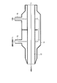
- Sectional drawing which shows the structure of the heat exchanger shown in FIG.
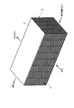
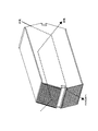
- the perspective view which shows the external appearance structure of the sensible heat exchanger shown in FIG.
- the perspective view which looked at a mode that the air-conditioning system shown in Drawing 1 was carried in vehicles from the front diagonal upper part of vehicles
- the side view which looked at a mode that the air-conditioning system shown in Drawing 1 was carried in vehicles from the side of vehicles.
- Diagram showing counter flow sensible heat exchanger The figure which shows schematic structure of the air conditioning system which concerns on Embodiment 2 of this invention. Schematic showing how the air conditioning system shown in FIG.
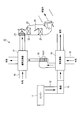
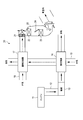
- FIG. 1 is a diagram showing a schematic configuration of an air conditioning system 10 according to Embodiment 1 of the present invention.
- solid arrows indicate the flow of exhaust gas
- dotted arrows indicate the flow of outside air.
- the engine 11 generates power by mixing highly volatile fuel (such as gasoline or light oil) and air and combusting it.
- the engine 11 discharges exhaust gas generated by combustion into the exhaust passage 12.
- the catalyst 13 is provided in the exhaust passage 12 and is made of platinum, palladium, rhodium or the like, and contains harmful components (mainly hydrocarbons, carbon monoxide, nitrogen oxides) contained in the exhaust gas discharged from the engine 11. Is purified by oxidation or reduction, and the purified exhaust gas is discharged to the heat exchanger 14. In the catalyst 13, high-temperature reaction heat is generated by the oxidation-reduction reaction.
- the heat exchanger 14 (corresponding to the first heat exchanger) is made of stainless steel, for example, and is provided in the exhaust passage 12 downstream of the catalyst 13. Further, as shown in FIG. 2, the heat exchanger 14 is configured such that the exhaust passage 12 and the first air passage 15 for introducing outside air are in contact with each other so that heat exchange is possible, and the exhaust gas and the outside air are not mixed. ing.
- the heat exchanger 14 performs heat exchange between the exhaust gas and the outside air, and dissipates heat from the high temperature exhaust gas to the low temperature outside air.
- the exhaust gas discharged from the heat exchanger 14 is exhausted outside the vehicle, and the outside air discharged from the heat exchanger 14 is supplied to the sensible heat exchanger 17 via the blower 16.
- the blower 16 is provided in the first air passage 15 that connects the heat exchanger 14 and the sensible heat exchanger 17, sucks the outside air heated in the heat exchanger 14, and blows the sucked outside air to the sensible heat exchanger 17. To do.
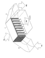
- the sensible heat exchanger 17 (corresponding to the second heat exchanger) is made of, for example, aluminum or polypropylene, and is a static heat exchanger having a fixed flow path as shown in FIG.
- the sensible heat exchanger 17 has two adjacent channels A and B. Low temperature outside air flows through one channel A and high temperature outside air flows through the other channel B. Thereby, in the sensible heat exchanger 17, the heat of the air of the flow path B can be moved to the air of the flow path A without mixing the air of the flow path A and the flow path B.
- a large number of fine channels are provided in the channels A and B of each system, and the contact areas of the channels A and B of the two systems are increased by arranging the fine channels of each system so as to intersect each other. .
- the first air passage 15 is connected to one end and the other end of the flow path B in the sensible heat exchanger 17.
- An HVAC (Heating, Ventilation, and Air Conditioning) 20 is disposed on the compartment side of a not-illustrated partition wall (firewall) that separates the engine room and the passenger compartment, and a blower 21 for blowing air and a blower passage of the blower 21
- the cooling air refrigerant heat exchanger 22 and the heating air refrigerant heat exchanger 23 constituting the heat pump cycle, and the switching door 24, which are sequentially arranged from the upstream side to the downstream side, are provided with a cooling air refrigerant heat. Air that has been temperature-controlled by the exchanger 22 and the heating air refrigerant heat exchanger 23 is blown into the passenger compartment to air-condition the passenger compartment.
- the air conditioning system 10 allows the outside air sucked from the suction port of the first air passage 15 to be heat-exchanged and then exhausted outside the passenger compartment, so that the exhaust gas is discharged even when the heat exchanger 14 is damaged.
- the mixed air can be exhausted outside the passenger compartment without being circulated.
- the air conditioning system 10 performs heat exchange between the exhaust gas and the outside air in the heat exchanger 14, and further performs heat exchange between the heated high temperature outside air and the low temperature outside air in the sensible heat exchanger 17. Even when the heat exchanger 14 is damaged by the two-stage heat exchange, the exhaust gas can be prevented from flowing into the passenger compartment. Further, since it is not necessary to provide the exhaust passage 12 with a means for detecting the exhaust gas concentration and a device for blocking the inflow of the exhaust gas, the air conditioning system 10 can be easily maintained.
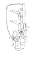
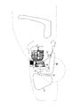
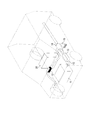
- FIG. 4 is a schematic diagram showing a state where the air conditioning system 10 shown in FIG. 1 is mounted on a vehicle.
- the suction port of the first air passage 15 has an opening facing the rear of the vehicle and is provided at the bottom of the vehicle, and outside air is sucked from the suction port by the blower 16.
- the discharge port of the first air passage 15 is provided under the floor of the vehicle, and the high temperature outside air discharged from the discharge port is guided to the air flow generated by the rotation of the tire during traveling.
- the suction port of the second air passage 18 is generally provided at the lower part of the cowl top in front of the windshield, and is an existing air suction port (HVAC outdoor air suction port).
- HVAC outdoor air suction port HVAC outdoor air suction port
- the outlet of the second air passage 18 is directly connected to the blower 21 of the HVAC 20 (see FIG. 1).
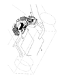
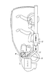
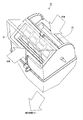
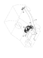
- FIG. 5 is a perspective view of the air-conditioning system 10 shown in FIG. 1 mounted on the vehicle as seen from the diagonally upper front of the vehicle
- FIG. 6 is a side view seen from the side of the vehicle.
- the sensible heat exchanger 17 is arranged so that the flow path A faces the front-rear direction of the vehicle and the flow path B faces the left-right direction of the vehicle. Moreover, the sensible heat exchanger 17 is arrange
- the outside air sucked from the suction port of the first air passage 15 is heat-exchanged and then exhausted outside the passenger compartment.
- the air mixed with the exhaust gas is exhausted outside the passenger compartment without being circulated.
- the substance contained in the exhaust gas does not accumulate in the first air passage 15 and can prevent the heat exchange efficiency from being lowered.
- the heat exchanger 14 that performs heat exchange between the exhaust gas and the outside air, and the heat exchange between the high temperature outside air heated in the heat exchanger 14 and the low temperature outside air that is introduced into the vehicle interior.
- the first air passage 15 is not a circulation passage, the number of pipes constituting the first air passage 15 can be reduced even if the first heat exchanger and the second heat exchanger are arranged at positions separated from each other. Therefore, it is possible to give these arrangements a degree of freedom.
- the air conditioning system 10 can be easily maintained.
- the sensible heat exchanger has been described by taking the case of a cross flow type as shown in FIG. 3, but the present invention is not limited to this.
- a counter-flow sensible heat exchanger may be used.
- FIG. 8 is a diagram showing a schematic configuration of an air conditioning system 30 according to Embodiment 2 of the present invention.
- FIG. 8 differs from FIG. 1 in that the blower 16 is deleted, and other configurations are the same as those in FIG.
- FIG. 9 is a schematic diagram illustrating a state in which the air conditioning system 30 illustrated in FIG. 8 is mounted on a vehicle.
- FIG. 10 illustrates a state in which the air conditioning system 30 illustrated in FIG. FIG.
- the suction port of the first air passage 15 is provided at the bottom of the vehicle with the opening facing the front of the vehicle, and outside air is sucked from the suction port as the vehicle travels. Thereby, it is not necessary to provide a blower in the first air passage 15, and the apparatus scale and cost can be reduced.
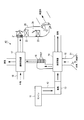
- FIG. 11 is a diagram showing a schematic configuration of an air conditioning system 40 according to the third embodiment of the present invention.
- FIG. 11 differs from FIG. 1 in that an outside air / inside air switching device 31 for switching the air sucked from the inlet of the first air passage 15 between the outside air and the inside air of the vehicle interior is added. It is the same.
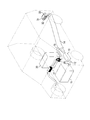
- FIG. 12 is a schematic diagram showing a state where the air conditioning system 40 shown in FIG. 11 is mounted on a vehicle.
- the heat exchanger 14 is provided over the entire exhaust passage 12 on the downstream side of the catalyst 13, and the inlet of the first air passage 15 is provided near the outlet of the exhaust passage 12.
- the outside air / inside air switching device 31 is provided at the suction port of the first air passage 15. Further, as shown in FIG. 13, the inside air / outside air switch 31 includes an inside air inlet 32 and an outside air inlet 33, and switches the opening between the inside air inlet 32 and the outside air inlet 33.
- the inside air inlet 32 is connected to an existing air (inside air) outlet (for example, near the rear pillar, near the tail lamp drafter, etc.) and sucks in the inside air.
- the outside air inlet 33 sucks outside air from the rear of the vehicle.
- the outside air / inside air switching unit 31 sucks in the inside air when the engine is started at a low temperature, and sucks in the outside air when the engine temperature reaches a certain temperature.
- the immediate warming property and the thermal efficiency can be improved, and when the engine temperature reaches a certain temperature, the outside air is prevented from becoming too high and the temperature can be easily adjusted.
- the outside air / inside air switching device 31 that switches the air sucked from the suction port of the first air passage 15 connecting the heat exchanger 14 and the sensible heat exchanger 17 between the outside air and the inside air.
- the warm-up performance is improved by inhaling the inside air when the engine is started at a low temperature, and the outside air is prevented from becoming too hot by inhaling the outside air when the engine temperature reaches a certain temperature. Easy to adjust the temperature.
- FIG. 14 is a diagram showing a schematic configuration of an air conditioning system 50 according to Embodiment 4 of the present invention.
- FIG. 14 differs from FIG. 1 in that the air sucked into the suction port of the first air passage 15 is used as the inside air in the passenger compartment, and the other configurations are the same as those in FIG.
- FIG. 15 is a schematic diagram showing a state in which the air conditioning system 50 shown in FIG. 14 is mounted on a vehicle.
- the heat exchanger 14 is provided over the entire exhaust passage 12 on the downstream side of the catalyst 13.
- the first air passage 15 is provided with an inside air inlet 32, and the inside air inlet 32 is provided near the outlet of the exhaust passage 12.
- the inside air inlet 32 is connected to an existing air (inside air) outlet (for example, near the rear pillar, a tail lamp drafter, etc.) and sucks in the inside air.
- an existing air (inside air) outlet for example, near the rear pillar, a tail lamp drafter, etc.
- the sensible heat exchanger 17 in each embodiment described above may be provided with a heat storage material 51 for storing heat.
- a plurality of heat storage materials 51 are arranged in the vertical direction at the outlet of the sensible heat exchanger 17 into the vehicle compartment, and the heat of the outside air heated by the sensible heat exchanger 17 is stored.
- the heat storage material 51 is provided so as not to hinder the flow of air.
- the heat stored in the heat storage material 51 can be used, and the warmth can be improved immediately.
- the vehicle heating device according to the present invention can be applied to a vehicle having an internal combustion engine such as a gasoline engine or a diesel engine.
Landscapes
- Engineering & Computer Science (AREA)
- Mechanical Engineering (AREA)
- Chemical & Material Sciences (AREA)
- Combustion & Propulsion (AREA)
- Physics & Mathematics (AREA)
- Thermal Sciences (AREA)
- General Engineering & Computer Science (AREA)
- Air-Conditioning For Vehicles (AREA)
Priority Applications (3)
| Application Number | Priority Date | Filing Date | Title |
|---|---|---|---|
| CN201480042629.0A CN105431312A (zh) | 2013-08-06 | 2014-07-30 | 车辆用制热装置 |
| US14/905,783 US20160250908A1 (en) | 2013-08-06 | 2014-07-30 | Vehicle heating device |
| EP14834856.8A EP3031639A4 (en) | 2013-08-06 | 2014-07-30 | Vehicle heating device |
Applications Claiming Priority (2)
| Application Number | Priority Date | Filing Date | Title |
|---|---|---|---|
| JP2013-163046 | 2013-08-06 | ||
| JP2013163046A JP2015030421A (ja) | 2013-08-06 | 2013-08-06 | 車両用暖房装置 |
Publications (1)
| Publication Number | Publication Date |
|---|---|
| WO2015019577A1 true WO2015019577A1 (ja) | 2015-02-12 |
Family
ID=52460934
Family Applications (1)
| Application Number | Title | Priority Date | Filing Date |
|---|---|---|---|
| PCT/JP2014/003991 Ceased WO2015019577A1 (ja) | 2013-08-06 | 2014-07-30 | 車両用暖房装置 |
Country Status (5)
| Country | Link |
|---|---|
| US (1) | US20160250908A1 (enExample) |
| EP (1) | EP3031639A4 (enExample) |
| JP (1) | JP2015030421A (enExample) |
| CN (1) | CN105431312A (enExample) |
| WO (1) | WO2015019577A1 (enExample) |
Cited By (2)
| Publication number | Priority date | Publication date | Assignee | Title |
|---|---|---|---|---|
| JP6456456B1 (ja) * | 2017-10-31 | 2019-01-23 | 三菱電機株式会社 | 車両用空調装置 |
| CN113619349A (zh) * | 2020-05-08 | 2021-11-09 | 上海汽车集团股份有限公司 | 车辆暖风系统及发动机冷却系统 |
Families Citing this family (6)
| Publication number | Priority date | Publication date | Assignee | Title |
|---|---|---|---|---|
| DE102014209274B4 (de) * | 2014-05-16 | 2023-08-17 | Bayerische Motoren Werke Aktiengesellschaft | Fahrzeug mit einem Verbrennungsmotor und einem Abwärmesammelgehäuse |
| DE102014209275B4 (de) | 2014-05-16 | 2023-06-07 | Bayerische Motoren Werke Aktiengesellschaft | Fahrzeug mit einem Verbrennungsmotor und einem Abwärmesammelgehäuse |
| JP6414344B2 (ja) | 2015-12-02 | 2018-10-31 | 株式会社デンソー | 気流制御システム |
| CN107160975B (zh) * | 2017-06-30 | 2024-01-12 | 高志男 | 车辆 |
| US10815931B2 (en) * | 2017-12-14 | 2020-10-27 | Cummins Inc. | Waste heat recovery system with low temperature heat exchanger |
| JP6580195B1 (ja) * | 2018-04-27 | 2019-09-25 | 三菱電機株式会社 | 車両用熱交換装置 |
Citations (5)
| Publication number | Priority date | Publication date | Assignee | Title |
|---|---|---|---|---|
| JPS5926010U (ja) * | 1982-08-12 | 1984-02-17 | 三菱電機株式会社 | 自動車の暖房器 |
| JPS62139711A (ja) * | 1985-12-12 | 1987-06-23 | Toyota Motor Corp | 車両用蓄熱ヒ−タ |
| JPH0725229A (ja) * | 1993-07-08 | 1995-01-27 | Mazda Motor Corp | 車両用空調装置 |
| JP2005282503A (ja) | 2004-03-30 | 2005-10-13 | Honda Motor Co Ltd | 自動車の暖房装置 |
| JP2009234389A (ja) * | 2008-03-26 | 2009-10-15 | Calsonic Kansei Corp | 車両用空気調和装置 |
Family Cites Families (5)
| Publication number | Priority date | Publication date | Assignee | Title |
|---|---|---|---|---|
| FR713137A (fr) * | 1931-03-12 | 1931-10-22 | Installation de chauffage et de ventilation pour automobiles | |
| US2341549A (en) * | 1942-02-19 | 1944-02-15 | Paul F Helmick | Heater |
| US4412425A (en) * | 1980-12-09 | 1983-11-01 | Nippon Soken, Inc. | Air conditioning and ventilation system |
| US6865901B2 (en) * | 2002-05-29 | 2005-03-15 | Webasto Thermosysteme International Gmbh | System with an internal combustion engine, a fuel cell and a climate control unit for heating and/or cooling the interior of a motor vehicle and process for the operation thereof |
| JP5967403B2 (ja) * | 2011-12-05 | 2016-08-10 | パナソニックIpマネジメント株式会社 | 車両用空調装置 |
-
2013
- 2013-08-06 JP JP2013163046A patent/JP2015030421A/ja not_active Withdrawn
-
2014
- 2014-07-30 EP EP14834856.8A patent/EP3031639A4/en not_active Withdrawn
- 2014-07-30 US US14/905,783 patent/US20160250908A1/en not_active Abandoned
- 2014-07-30 WO PCT/JP2014/003991 patent/WO2015019577A1/ja not_active Ceased
- 2014-07-30 CN CN201480042629.0A patent/CN105431312A/zh active Pending
Patent Citations (5)
| Publication number | Priority date | Publication date | Assignee | Title |
|---|---|---|---|---|
| JPS5926010U (ja) * | 1982-08-12 | 1984-02-17 | 三菱電機株式会社 | 自動車の暖房器 |
| JPS62139711A (ja) * | 1985-12-12 | 1987-06-23 | Toyota Motor Corp | 車両用蓄熱ヒ−タ |
| JPH0725229A (ja) * | 1993-07-08 | 1995-01-27 | Mazda Motor Corp | 車両用空調装置 |
| JP2005282503A (ja) | 2004-03-30 | 2005-10-13 | Honda Motor Co Ltd | 自動車の暖房装置 |
| JP2009234389A (ja) * | 2008-03-26 | 2009-10-15 | Calsonic Kansei Corp | 車両用空気調和装置 |
Non-Patent Citations (1)
| Title |
|---|
| See also references of EP3031639A4 |
Cited By (3)
| Publication number | Priority date | Publication date | Assignee | Title |
|---|---|---|---|---|
| JP6456456B1 (ja) * | 2017-10-31 | 2019-01-23 | 三菱電機株式会社 | 車両用空調装置 |
| JP2019081460A (ja) * | 2017-10-31 | 2019-05-30 | 三菱電機株式会社 | 車両用空調装置 |
| CN113619349A (zh) * | 2020-05-08 | 2021-11-09 | 上海汽车集团股份有限公司 | 车辆暖风系统及发动机冷却系统 |
Also Published As
| Publication number | Publication date |
|---|---|
| JP2015030421A (ja) | 2015-02-16 |
| CN105431312A (zh) | 2016-03-23 |
| EP3031639A4 (en) | 2017-03-22 |
| US20160250908A1 (en) | 2016-09-01 |
| EP3031639A1 (en) | 2016-06-15 |
Similar Documents
| Publication | Publication Date | Title |
|---|---|---|
| WO2015019577A1 (ja) | 車両用暖房装置 | |
| JP5588472B2 (ja) | 車載用空調装置および車両 | |
| US20080110185A1 (en) | Vehicle HVAC system | |
| JPWO2013128618A1 (ja) | 車両前部構造 | |
| JP2009021215A (ja) | 燃料電池スタックケースの換気装置 | |
| US20190092143A1 (en) | Vehicle air-conditioning device | |
| JP2013180614A (ja) | 車両用電池温度制御構造 | |
| JP5772652B2 (ja) | 車両の冷却装置 | |
| JP2015160460A (ja) | 自動車用空調装置 | |
| JP2011126522A (ja) | 構成部品の支持体を備える空調システム | |
| CN102971165A (zh) | 设计用于再生过滤器的供暖、通风和/或空调装置及其实施方法 | |
| JP2008222041A (ja) | 自動車のバッテリ冷却装置 | |
| JP5507602B2 (ja) | 車両の外気導入構造 | |
| JP7186890B2 (ja) | 車両 | |
| KR101678380B1 (ko) | 전기 자동차용 대향류 현열교환기를 장착한 폐열회수 환기 시스템 | |
| US20110073281A1 (en) | Heat exchanger for vehicular air conditioning apparatus | |
| KR20200069894A (ko) | 차량용 후석 공조장치 | |
| US20180009292A1 (en) | Vehicular air conditioning device | |
| JP7147182B2 (ja) | 車両 | |
| JP2024034493A (ja) | 吸湿カートリッジ及びこれを用いた自動車の空調装置 | |
| JP7147181B2 (ja) | 車両 | |
| JP5256918B2 (ja) | 車両の空調装置 | |
| JPH0577641A (ja) | 天井設置型車両用クーリングユニツト | |
| JP6667013B1 (ja) | 電気自動車 | |
| JPH106740A (ja) | 車両用空調装置 |
Legal Events
| Date | Code | Title | Description |
|---|---|---|---|
| WWE | Wipo information: entry into national phase |
Ref document number: 201480042629.0 Country of ref document: CN |
|
| 121 | Ep: the epo has been informed by wipo that ep was designated in this application |
Ref document number: 14834856 Country of ref document: EP Kind code of ref document: A1 |
|
| WWE | Wipo information: entry into national phase |
Ref document number: 14905783 Country of ref document: US |
|
| WWE | Wipo information: entry into national phase |
Ref document number: 2014834856 Country of ref document: EP |
|
| NENP | Non-entry into the national phase |
Ref country code: DE |