WO2015019427A1 - Système de batterie - Google Patents
Système de batterie Download PDFInfo
- Publication number
- WO2015019427A1 WO2015019427A1 PCT/JP2013/071305 JP2013071305W WO2015019427A1 WO 2015019427 A1 WO2015019427 A1 WO 2015019427A1 JP 2013071305 W JP2013071305 W JP 2013071305W WO 2015019427 A1 WO2015019427 A1 WO 2015019427A1
- Authority
- WO
- WIPO (PCT)
- Prior art keywords
- battery
- charge
- upper limit
- limit voltage
- side reaction
- Prior art date
Links
Images


Classifications
-
- H—ELECTRICITY
- H01—ELECTRIC ELEMENTS
- H01M—PROCESSES OR MEANS, e.g. BATTERIES, FOR THE DIRECT CONVERSION OF CHEMICAL ENERGY INTO ELECTRICAL ENERGY
- H01M10/00—Secondary cells; Manufacture thereof
- H01M10/42—Methods or arrangements for servicing or maintenance of secondary cells or secondary half-cells
- H01M10/44—Methods for charging or discharging
-
- H—ELECTRICITY
- H01—ELECTRIC ELEMENTS
- H01M—PROCESSES OR MEANS, e.g. BATTERIES, FOR THE DIRECT CONVERSION OF CHEMICAL ENERGY INTO ELECTRICAL ENERGY
- H01M10/00—Secondary cells; Manufacture thereof
- H01M10/42—Methods or arrangements for servicing or maintenance of secondary cells or secondary half-cells
- H01M10/48—Accumulators combined with arrangements for measuring, testing or indicating the condition of cells, e.g. the level or density of the electrolyte
-
- H—ELECTRICITY
- H02—GENERATION; CONVERSION OR DISTRIBUTION OF ELECTRIC POWER
- H02J—CIRCUIT ARRANGEMENTS OR SYSTEMS FOR SUPPLYING OR DISTRIBUTING ELECTRIC POWER; SYSTEMS FOR STORING ELECTRIC ENERGY
- H02J7/00—Circuit arrangements for charging or depolarising batteries or for supplying loads from batteries
-
- Y—GENERAL TAGGING OF NEW TECHNOLOGICAL DEVELOPMENTS; GENERAL TAGGING OF CROSS-SECTIONAL TECHNOLOGIES SPANNING OVER SEVERAL SECTIONS OF THE IPC; TECHNICAL SUBJECTS COVERED BY FORMER USPC CROSS-REFERENCE ART COLLECTIONS [XRACs] AND DIGESTS
- Y02—TECHNOLOGIES OR APPLICATIONS FOR MITIGATION OR ADAPTATION AGAINST CLIMATE CHANGE
- Y02E—REDUCTION OF GREENHOUSE GAS [GHG] EMISSIONS, RELATED TO ENERGY GENERATION, TRANSMISSION OR DISTRIBUTION
- Y02E60/00—Enabling technologies; Technologies with a potential or indirect contribution to GHG emissions mitigation
- Y02E60/10—Energy storage using batteries
Definitions
- the technical field of the present invention relates to a battery system using a lithium ion secondary battery.
- Lithium ion secondary batteries are, for example, ships, railroads, and automobiles (hybrid electric vehicles, plug-in hybrid vehicles, electric vehicles) as batteries capable of increasing energy density and output density. Etc.), widely used in electronic devices, stationary power storage systems, and the like.
- technologies for storing electric power generated by using natural energy such as wind power and sunlight in a battery and storing electric power from the grid are attracting attention for both home and industrial use.
- a smart grid no-generation power transmission network
- IT Information Technology
- JP 2011-228052 A According to the technique disclosed in Japanese Patent Application Laid-Open No. 2012-85452, according to the technique disclosed in Patent Document 1, “the actual capacity per unit area at the time of initial charging up to 0 V with respect to the metallic lithium of the negative electrode” By providing a battery with “the battery capacity is hardly reduced even if the amount of active material used is reduced than before” by making it smaller than "actual capacity per unit area at the time of first charge up to 7V" Yes.
- Patent Document 2 does not describe how much the upper limit voltage is increased. Further, although “lithium electrodeposition” is considered, the concern that the positive electrode becomes overcharged as the upper limit voltage increases and heat generation and deterioration are promoted is not taken into consideration.
- deterioration over time such as a decrease in battery capacity
- a capacity shift caused by a side reaction of the negative electrode a side reaction is a reaction other than a charge / discharge reaction, for example, a reaction in which an electrolytic solution is polymerized to form a film on the negative electrode surface. It is done.
- the battery When the capacity shift occurs, the battery is judged to be fully charged due to the potential increase of the positive electrode even though the negative electrode has a further capacity to charge, and further charging stops. Although it can be avoided by increasing the charging upper limit voltage, a disordered increase in the upper limit voltage causes not only lithium metal deposition but also overcharge of the positive electrode and acceleration of deterioration.
- the present invention has been made in view of such circumstances, and is to provide a more appropriate charge / discharge control method for a lithium ion secondary battery and a battery system using the same.
- the battery system according to the present invention includes a lithium ion secondary battery in which a positive electrode and a negative electrode are wound through a separator, a controller that gives a charge / discharge instruction to the lithium ion secondary battery, and a charge / discharge control signal output to the controller. It has a charge / discharge control device that controls the charge / discharge of the lithium ion secondary battery, and the charge / discharge control device calculates the side reaction amount of the battery based on the battery information acquired by the battery information acquisition unit and the battery information acquisition unit.
- the calculation unit calculates a new charge upper limit voltage obtained by adding a predetermined proportion of the side reaction amount to the initial charge upper limit voltage, and when the side reaction amount becomes equal to or greater than the threshold, the new charge upper limit voltage is calculated. And sets as the charge upper limit voltage.
- a more appropriate charge / discharge control method for a lithium ion secondary battery and a battery system using the same can be provided.
- the figure which shows the structure of the lithium ion secondary battery concerning this embodiment Block diagram of the charge / discharge control device of this embodiment Example of analysis inside battery (positive / negative state) by battery measurement information Charging curve of LiNi 1/3 Co 1/3 Mn 1/3 O 2
- FIG. 1A is a longitudinal sectional view of the lithium ion secondary battery 1.
- the lithium ion secondary battery 1 is arranged above and below an electrode group 3 in which a positive electrode sheet and a negative electrode sheet are wound around a shaft 2 via a separator, a battery can 4 that houses the electrode group 3, and the electrode group 3.
- the battery cover 3 is electrically connected to the electrical insulating plate 5 and the electrode group 3.
- the electrical insulating plate 5 is disposed so as to sandwich the electrode group 3 from above and below, and has a structure such that the electrode group 3 does not contact the lid 6 when vibration is applied to the lithium ion secondary battery 1.
- the active material uncoated portion of the positive electrode sheet of the electrode group 3 is connected to the conductive lead 7.
- the conductive lead 7 is led out from one side of the electrode group 3 and connected to the lid 6 so that electric power can be supplied to the outside.
- the active material uncoated portion of the negative electrode sheet of the electrode group 3 is connected to the conductive lead 8.
- the conductive lead 8 is led out from the other side of the electrode group 3 (the side opposite to the side where the lid 6 is provided) and is electrically connected to the bottom surface of the battery can 4.
- the battery lid 6 is connected to a conductive plate to which a conductive lead 7 is connected, and is fixed by caulking the opening of the battery can 4 after the electrolyte is injected into the battery can 4. Note that when the opening of the battery can 4 is caulked, a gasket 9 is disposed between the battery lid 6 and the battery can 4 and caulked to maintain hermeticity.
- FIG. 1 (b) is a cross-sectional view taken along the line AA of FIG. 1 (a).
- the shaft core 2 is arranged at a substantially central portion of the battery can 3 and the electrode group 3 is arranged on the outer peripheral portion thereof.
- an insulating sheet is interposed between the electrode group 3 and the battery can 4.
- Each lithium ion secondary battery 1 is provided with a cell controller 11.
- the cell controller 11 includes memories such as a CPU (Central Processing Unit), a ROM (Read Only Memory), a RAM (Random Access Memory), and an HDD (Hard Disk Drive), and is controlled by a charge / discharge control device 100 described later. In response to the signal, charging / discharging of the lithium ion secondary battery 1 is limited.
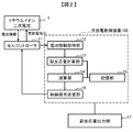
- the charge / discharge control apparatus 100 includes a battery information acquisition unit 12 configured by a CPU, a side reaction amount calculation unit 13, a calculation unit 14, a control signal transmission unit 16, and a storage unit configured by a memory such as a ROM, a RAM, and an HDD. 15.
- the battery information acquisition unit 12 receives battery information acquired by the cell controller 11. More specifically, the battery information is the terminal voltage of the lithium ion secondary battery 1 (closed circuit voltage; hereinafter simply referred to as “battery voltage”), the current flowing through the lithium ion secondary battery 1, lithium ion The information of the temperature of the secondary battery 1 and charging / discharging time is said.
- Specific means for measuring the battery voltage of the lithium ion secondary battery 1 includes, for example, a voltmeter (not shown). Further, as a specific means for measuring the current flowing through the lithium ion secondary battery 1, for example, an ammeter (not shown) can be cited.
- thermocouple (not shown) is mentioned, for example.
- charge / discharge time measurement in the lithium ion secondary battery 1 examples include a timer (not shown).
- the side reaction amount calculation unit 13 calculates the side reaction amount, which is a feature of the present invention, based on the information acquired by the battery information acquisition unit 12. The calculation of the side reaction amount will be described later.
- This amount of side reaction is information that serves as an indicator of the deterioration state of the lithium ion secondary battery 1, and is, for example, the amount of reaction in which the electrolytic solution or the like is polymerized to form a film on the negative electrode surface.
- the calculation unit 14 calculates the charge upper limit voltage based on the side reaction amount calculated by the side reaction amount calculation unit 13 and the past battery information stored in the storage unit 15 as described above.
- the control signal transmission unit 16 receives the information on the charge upper limit voltage calculated by the calculation unit 14, generates a control signal, and transmits a control signal for charge / discharge instruction to the cell controller 11.
- the charge / discharge control apparatus 100 may be connected to a side reaction amount output unit 17 constituted by a display.
- the side reaction output unit 17 displays the side reaction amount calculated by the side reaction amount calculation unit 13. Therefore, the user can grasp the degree of deterioration of the battery. It is also possible to achieve optimum operation of the entire system by outputting the change to the host system.
- the side reaction amount calculation unit 13 can calculate the side reaction amount based on the voltage, current, and charge / discharge time of the lithium ion secondary battery 1 by one of the following two methods. .
- (1) Method Using Charging and / or Discharging Curve Analysis In this embodiment, a side reaction amount is calculated using a discharging curve. An example of calculating the side reaction amount is shown in FIG.
- the side reaction amount calculation unit 13 first calculates the discharge curve of the lithium ion secondary battery 1.
- the battery voltage is determined by the difference between the positive electrode potential and the negative electrode potential. That is, the difference in potential indicated by the positive electrode discharge curve and the negative electrode discharge curve is the battery voltage.
- a discharge curve of the lithium ion secondary battery 1 is created based on the information on the battery voltage.
- the side reaction amount calculation unit 13 separates the discharge curve of the lithium ion secondary battery 1 into a discharge curve of the positive electrode operating in the lithium ion secondary battery 1 and a discharge curve of the negative electrode.
- the battery voltage is differentiated by the capacity in the calculated discharge curve of the lithium ion secondary battery 1.
- a curve obtained by differentiating the voltage with respect to the capacity in the positive electrode discharge curve and a curve obtained by differentiating the voltage of the negative electrode discharge curve with the capacity coincide with the differential curve of the discharge curve of the lithium ion secondary battery 1.
- the scale of the positive and negative electrodes is changed, and the discharge start position (defined as zero position) of the single electrode is moved in the capacity axis direction.
- the relative value between the zero point of the positive electrode and the zero point of the negative electrode is calculated with respect to the capacity axis.
- the positive electrode and negative electrode data described above may be acquired in advance and stored in the storage unit 15.
- the zero point of the negative electrode with respect to the capacity axis is calculated again.
- the initial state is defined, for example, immediately after manufacture or in a state of being discharged several times after manufacture).
- Lithium ion after repeating the zero point of the negative electrode and charging / discharging a predetermined number of times (here, the predetermined number of times is the number of times of charging / discharging repeated until the amount of side reaction is calculated from the initial state described above).
- the zero point of the negative electrode with respect to the capacity axis of the secondary battery 1 is compared, and the change amount (difference amount) is calculated as a side reaction amount.
- the reference point for calculating the side reaction amount is calculated based on the position of the zero point of the negative electrode.
- the reference point for calculating the side reaction amount may not be the position of the zero point of the negative electrode. Good.
- the value before and after deterioration may be compared using the capacity axis value of the negative electrode potential corresponding to the specific potential (eg, 4.1 V) of the positive electrode potential as a reference point.
- comparison may be made before and after deterioration with reference to the point where the capacity is halved.
- a charge curve may be used.
- the side reaction amount can be estimated in the same manner as in the discharge curve analysis by using the charge curve of the single positive and negative electrode and its differential curve.
- a reference electrode is not provided in the lithium ion secondary battery 1, so that the battery can be miniaturized and a lithium ion secondary battery having a high volume capacity density is provided. can do.
- FIG. 4 is a charge curve of the active material LiNi 1/3 Co 1/3 Mn 1/3 O 2 .
- the changed charge upper limit voltage VB with respect to the initial charge upper limit voltage VA will be described.
- the storage unit 15 calculates and inputs and records the slope ( ⁇ V / ⁇ Q) of the charging curve of the initial lithium ion secondary battery 1 in accordance with the calculation of the side reaction amount, or stores the initial lithium ion secondary battery 1 in advance.
- the charging curve is memorized.
- ⁇ V / ⁇ Q used at this time is ⁇ V / ⁇ Q when VA or more.
- ⁇ Charging / discharging control method> a charge / discharge control method of the lithium ion secondary battery 1 by the charge / discharge control apparatus 100 shown in FIG. 2 will be described with reference to FIG.
- the battery information acquisition part 12 acquires the information (battery information; battery voltage, electric current, battery temperature, and charging / discharging time) about the lithium ion secondary battery 1 from the cell controller 11 (step S101; battery information acquisition step) ). Then, the battery information acquisition unit 12 transmits the acquired battery information of the lithium ion secondary battery 1 to the side reaction amount calculation unit 13.
- the side reaction amount calculation unit 13 calculates the side reaction amount using the above-described method (step S102; side reaction amount calculation step).
- the calculated side reaction amount is transmitted to the calculation unit 14 to determine whether or not “the side reaction has increased by 5% or more from the reference point of the negative electrode charge / discharge curve” in the lithium ion secondary battery 1 (step S103; determination) Step).
- the threshold value for increasing the side reaction amount is 5%. The smaller the threshold, the smaller the variation in battery capacity, which is preferable.
- step S104 charging upper limit voltage calculating step.
- the calculation result of the calculation unit 14 is transmitted to the cell controller 11 and the side reaction amount output unit 17 via the control signal transmission unit 16, and the control method is changed and output to the user and the host system (step S105).
- step S106 when it is determined that “the side reaction has not increased by 5% or more from the reference point of the negative electrode charging / discharging curve”, it waits for a predetermined time (step S106), and then transmits a signal to the battery information acquisition unit 12 To do. And the battery information acquisition part 12 acquires the battery information of the lithium ion secondary battery 1 again based on the information, and repeats from step S101 to step S103 until the amount of side reactions exceeds a predetermined threshold value.
- the usable battery capacity of the lithium ion secondary battery 1 that decreases by the increase in the side reaction amount is increased. It becomes possible to make it. Therefore, the usable battery capacity can be increased while suppressing the deterioration of the lithium ion secondary battery 1 due to the random increase in the charging upper limit voltage.
- the charge / discharge control method and the charge / discharge control apparatus according to the present embodiment have been described.
- a positive electrode capable of occluding and releasing lithium ions, and occluding and releasing lithium ions As the lithium ion secondary battery to which the embodiment can be applied, a positive electrode capable of occluding and releasing lithium ions, and occluding and releasing lithium ions.
- the specific configuration is not particularly limited as long as it includes a possible negative electrode and an electrolyte.
- the battery may be a battery using a non-aqueous electrolyte or a battery containing a lithium ion polymer.
- the battery may be a battery including a solid electrolyte or a battery including an ionic liquid.
- a separator may also be used as necessary.
- the battery voltage is constantly monitored, and when the voltage deviates from the range between the charge upper limit voltage and the discharge lower limit voltage, a signal for stopping charge / discharge is output or a signal notifying the abnormality Is preferably output. And in such a case, when the charge upper limit voltage is changed, it is more preferable that the voltage (threshold value) for outputting the signal is also changed. Therefore, the charge / discharge control device 100 outputs a signal when detecting that the voltage of the lithium ion secondary battery 1 has reached a predetermined voltage during charging / discharging of the lithium ion secondary battery 1 (illustration shown). Not).
- a safer system can be constructed by outputting a signal informing the abnormality of the signal output unit.
- the battery information acquisition unit 12 measures voltage, current, temperature, and charge / discharge time as battery information. If the side reaction amount of can be calculated, the battery information is not limited to these.
- Second Embodiment is different from the first embodiment in that, when two types of mixed active materials are used for the positive electrode, in addition to the side reaction amount, the charging upper limit voltage is determined from the operating voltage of each active material. Is different from the first embodiment.
- the charging upper limit voltage is increased, the battery capacity that can be used is increased. On the other hand, when the charging voltage is increased, deterioration of the battery may be promoted. Therefore, in the present embodiment, when a positive electrode composed of two active materials is used, the charge upper limit voltage VB calculated from ⁇ Q (side reaction) is higher in the potential flat portion of the two active materials. If it is determined that the potential is higher than the flat portion potential of the active material, the charging upper limit voltage is suppressed by suppressing the charging upper limit voltage with the flat portion potential of the active material having the larger potential flat portion potential. I can do it.
- the capacity of the active material having the larger potential of the potential flat portion can be used. Therefore, it is possible to increase the available capacity while suppressing the deterioration of the battery by suppressing the charging upper limit voltage.
- FIG. 6 is a diagram showing charging curves of the active material LiNi 1/3 Co 1/3 Mn 1/3 O 2 and the active material LiMnPO 4 .
- the side reaction amount is calculated by the side reaction amount calculation unit 13 in the same manner as in the first embodiment.
- the calculation unit 14 calculates ⁇ Q (side reaction) based on the side reaction amount calculated by the side reaction amount calculation unit 13, and calculates the charging upper limit voltage VB from ⁇ Q (side reaction).
- the potential V (4.12 V) of the potential flat portion of the active material LiMnPO 4 is stored in the storage unit 15 in advance, and information on the potential VC (4.12 V) of the potential flat portion of the active material LiMnPO 4 is calculated. Input to the unit 14. And when satisfy
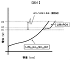
- FIG. 7 is a diagram showing a charging curve when three kinds of active materials of the active material LiNi 1/3 Co 1/3 Mn 1/3 O 2 , the active material LiMnPO 4 and the material LiMnCoPO 4 are used.
- the calculation unit 14 in addition to the charging upper limit voltage VB calculated from ⁇ Q (side reaction), the calculation unit 14 has the potential VC (4.12 V) of the potential flat portion of the active material LiMnPO4 and the potential VD (4.1V) of the material LiMnCoPO4 potential flat portion. 4.18) is used to calculate the charging upper limit voltage. Specifically, when VB is larger than the flat portion potential of the active material having the largest flat portion potential among the three active materials, the flat portion potential of the active material having the largest flat portion potential is charged. Set as the upper limit voltage. That is, when the following expression (3) is satisfied, the calculation unit 14 selects VD as the charge upper limit voltage. [Equation 3] VB ⁇ VD
- VD By selecting the VD in this way, it is possible to increase the usable battery capacity while suppressing deterioration compared to the second embodiment.
- the charge upper limit voltage can be set to a value between VC and VD.
- the calculation unit 14 sets the charge upper limit voltage to a value between VC and VD, the battery capacity can be recovered twice stepwise by setting the charge upper limit voltage to VD thereafter.
- the threshold value for increasing the side reaction amount can be arbitrarily determined.
- Example 1 Preparation of positive electrode> 88 parts by mass of LiNi 1/3 Co 1/3 Mn 1/3 O 2 as a positive electrode active material, 1 part by mass of artificial graphite as a conductive additive, 1 part by mass of acetylene black, and PVDF as a binder: 10 A mass part was mixed so as to be uniform using NMP as a solvent to prepare a positive electrode mixture-containing paste.
- the positive electrode mixture-containing paste was intermittently applied to both surfaces of an aluminum foil (thickness: 15 ⁇ m) while adjusting the thickness, dried, and then subjected to press treatment to adjust the thickness of the positive electrode mixture layer to produce a positive electrode.
- ⁇ Production of negative electrode> 98 parts by mass of graphite having an average particle diameter D50 of 20 ⁇ m, 1 part by mass of CMC, and 1 part by mass of SBR were mixed and diluted with pure water to prepare an aqueous negative electrode mixture-containing paste.
- the negative electrode mixture-containing paste is intermittently applied to both sides of a current collector made of copper foil with a thickness of 8 ⁇ m by adjusting the thickness, dried, and then pressed to adjust the thickness of the negative electrode mixture layer. Thus, a negative electrode was produced.
- graphite is used, but an alloy negative electrode containing Si, Su, or the like may be used.
- LiPF 6 as a lithium salt was dissolved at a concentration of 1 mol / l in a mixture of ethylene carbonate, ethyl methyl carbonate and dimethyl carbonate in a volume ratio of 1: 1: 1 to prepare a non-aqueous electrolyte.
- ⁇ Battery assembly> The positive electrode and the negative electrode were cut into a predetermined size, and a wound electrode body was produced through a separator made of a microporous polyethylene film having a thickness of 30 ⁇ m and a porosity of 50%. This wound electrode body was inserted into a cylindrical battery can, and then the non-aqueous electrolyte was poured into the can and sealed to produce a cylindrical lithium ion secondary battery.
- the upper limit charging voltage of the cylindrical lithium ion secondary battery was 4.1 V
- the discharge lower limit voltage was 2.7 V
- charging / discharging was repeated 5 cycles at a current value of 1C (1C defined).
- the discharge capacity at the fifth cycle was the initial capacity
- the discharge curve at the fifth cycle was the initial discharge curve.
- the deterioration of the battery was simulated by performing 50 cycles, 100 cycles, 150 cycles, and 500 cycles.
- the battery charge upper limit voltage was changed.
- the capacity of the lithium ion secondary battery increased by about 5% after the change process compared to before the process.
- the method for calculating the amount of side reaction is described below.
- the initial discharge curve and its differential curve were separated into positive and negative discharge curves obtained in advance.
- the reference point of the positive electrode was a point of 4.1 V on the basis of lithium, and the capacity value from the point to the point at the end of charging of the negative electrode was defined as a capacity deviation.
- the separation process was performed on the discharge curve and its differential curve after a predetermined cycle. Then, the amount of side reaction was calculated by superimposing the separation processing results of the data after the fifth cycle and the data after the cycle.
- the capacity deviation is calculated using the discharge curve, but the same processing can be performed using the charge curve.
- Example 2 In this example, a battery different from Example 1 only in the positive electrode composition was prepared.
- Artificial graphite which is a conductive additive, is composed of 88 parts by mass of an active material obtained by mixing 90 parts by mass of LiNi 1/3 Co 1/3 Mn 1/3 O 2 as a positive electrode active material and 10 parts by mass of olivine Mn. 1 part by mass, acetylene black: 1 part by mass, and PVDF as a binder: 10 parts by mass were mixed so as to be uniform using NMP as a solvent to prepare a positive electrode mixture-containing paste.
- the positive electrode mixture-containing paste was intermittently applied to both surfaces of an aluminum foil (thickness: 15 ⁇ m) while adjusting the thickness, dried, and then subjected to press treatment to adjust the thickness of the positive electrode mixture layer to produce a positive electrode. . It was prepared by increasing the thickness of the positive electrode so that the total weight in the LiNi 1/3 Co 1/3 Mn 1/3 O 2 battery used as the main active material was equivalent to that in Example 1.
- the charging curve of the positive electrode of the battery prepared in this example is indicated by a broken line, and the charging curve of the battery prepared in Example 1 is indicated by a solid line.
- the main active material LiNi 1/3 Co 1/3 Mn 1/3 O 2 is not overcharged, and by adjusting the amount of olivine Mn, any capacity deviation Hidden capacity can be set for quantity.
- Example 3 In this example, a battery different from Example 1 only in the positive electrode composition was prepared.
- the positive electrode mixture-containing paste was intermittently applied to both surfaces of an aluminum foil (thickness: 15 ⁇ m) while adjusting the thickness, dried, and then subjected to press treatment to adjust the thickness of the positive electrode mixture layer to produce a positive electrode. . It was prepared by increasing the thickness of the positive electrode so that the total weight in the LiNi 1/3 Co 1/3 Mn 1/3 O 2 battery used as the main active material was equivalent to that in Example 1.
- FIG. 7 is a diagram in which the charging curve of the positive electrode of the battery prepared in this example is represented by a dotted line, the charging curve of the battery prepared in Example 1 is represented by a solid line, and the charging curve of the battery prepared in Example 2 is represented by a broken line. is there.
- the main active material LiNi 1/3 Co 1/3 Mn 1/3 O 2 can be arbitrarily adjusted by adjusting the amounts of olivine Mn and olivine MnCo without making the overcharged state.
- the capacity can be recovered multiple times by setting a hidden capacity for the capacity deviation amount and changing the charge upper limit voltage from A to B in FIG.
- Example 4 In this example, a battery different from Example 1 only in the positive electrode composition was prepared.
- the positive electrode mixture-containing paste was intermittently applied to both surfaces of an aluminum foil (thickness: 15 ⁇ m) while adjusting the thickness, dried, and then subjected to press treatment to adjust the thickness of the positive electrode mixture layer to produce a positive electrode. . It was prepared by increasing the thickness of the positive electrode so that the total weight in the LiNi 1/3 Co 1/3 Mn 1/3 O 2 battery used as the main active material was equivalent to that in Example 1.
- FIG. 8 is a diagram showing the results of Examples 1 to 4 and the comparative example.
- FIG. 8A shows the number of cycles and the capacity retention rate of the battery.
- the capacity retention rate after 500 cycles was 80%.
- the capacity retention rate became 85% after 500 cycles.
- the capacity retention rate after 500 cycles decreased to 75%.
- the capacity retention rate after 500 cycles was 80%.
- FIG. 8 (b) summarizes the calculation results of the side reaction amount.
- the amount of side reaction after 500 cycles was about 22%.
- the side reaction amount of the comparative example was 20% or less after 500 cycles. This difference in the amount of side reaction is due to the increase in the charge upper limit voltage, but even after 500 cycles, there is no significant difference between Examples 1 to 4 and the comparative example. Since the increase in the amount of side reaction promotes the deterioration of the battery, the fact that there is no significant difference between Examples 1 to 4 and the comparative example means that even if the control method of the present invention is used, the lithium ion It can be seen that the secondary battery 1 is not significantly degraded.
- the capacity maintenance rate of the battery can be improved without significantly increasing the deterioration of the battery.
- the present invention is not limited to the above-described embodiments, and various designs can be made without departing from the spirit of the present invention described in the claims. It can be changed.
- the above-described embodiment has been described in detail for easy understanding of the present invention, and is not necessarily limited to one having all the configurations described.
- a part of the configuration of an embodiment can be replaced with the configuration of another embodiment, and the configuration of another embodiment can be added to the configuration of an embodiment.
Landscapes
- Engineering & Computer Science (AREA)
- Manufacturing & Machinery (AREA)
- Chemical & Material Sciences (AREA)
- Chemical Kinetics & Catalysis (AREA)
- Electrochemistry (AREA)
- General Chemical & Material Sciences (AREA)
- Power Engineering (AREA)
- Secondary Cells (AREA)
Abstract
La présente invention concerne un procédé de commande de charge et de décharge plus approprié d'une batterie secondaire au lithium-ion et un système de batterie utilisant le procédé de commande de charge et de décharge. Le système de batterie selon la présente invention comporte : une batterie secondaire au lithium-ion qui loge un corps d'enroulement ; un organe de commande qui donne des instructions de charge et de décharge ; et un dispositif de commande de charge et de décharge qui délivre un signal de commande de charge et de décharge à l'organe de commande de façon à commander la charge et la décharge de la batterie secondaire au lithium-ion. Le dispositif de commande de charge et de décharge comporte : une unité d'acquisition d'informations de batterie ; une unité de calcul de quantité de réaction secondaire destinée, sur la base des informations de batterie acquises par l'unité d'acquisition d'informations de batterie, à calculer la quantité de réaction secondaire de la batterie ; une unité de calcul destinée, sur la base de la quantité de réaction secondaire calculée, à calculer une tension limite supérieure de charge ; et une unité de transmission de signal de commande destinée, sur la base de la tension limite supérieure de charge calculée, à délivrer le signal de commande de charge et de décharge à l'organe de commande. L'unité de calcul calcule une nouvelle tension limite supérieure de charge par addition d'un pourcentage prédéfini de la quantité de réaction secondaire à une tension limite supérieure de charge initiale et, lorsque la quantité de réaction secondaire dépasse une valeur seuil, fixe la nouvelle tension limite supérieure de charge en tant que tension limite supérieure de charge.
Priority Applications (1)
| Application Number | Priority Date | Filing Date | Title |
|---|---|---|---|
| PCT/JP2013/071305 WO2015019427A1 (fr) | 2013-08-07 | 2013-08-07 | Système de batterie |
Applications Claiming Priority (1)
| Application Number | Priority Date | Filing Date | Title |
|---|---|---|---|
| PCT/JP2013/071305 WO2015019427A1 (fr) | 2013-08-07 | 2013-08-07 | Système de batterie |
Publications (1)
| Publication Number | Publication Date |
|---|---|
| WO2015019427A1 true WO2015019427A1 (fr) | 2015-02-12 |
Family
ID=52460799
Family Applications (1)
| Application Number | Title | Priority Date | Filing Date |
|---|---|---|---|
| PCT/JP2013/071305 WO2015019427A1 (fr) | 2013-08-07 | 2013-08-07 | Système de batterie |
Country Status (1)
| Country | Link |
|---|---|
| WO (1) | WO2015019427A1 (fr) |
Cited By (3)
| Publication number | Priority date | Publication date | Assignee | Title |
|---|---|---|---|---|
| CN109511281A (zh) * | 2016-09-21 | 2019-03-22 | 日立汽车系统株式会社 | 二次电池控制装置 |
| CN112394298A (zh) * | 2020-12-01 | 2021-02-23 | 杭州沃伦森电气有限公司 | 电抗器匝间短路的检测方法 |
| US20230140094A1 (en) * | 2020-10-27 | 2023-05-04 | Lg Energy Solution, Ltd. | Battery Management Apparatus And Method |
Citations (5)
| Publication number | Priority date | Publication date | Assignee | Title |
|---|---|---|---|---|
| JP2002334719A (ja) * | 2001-05-07 | 2002-11-22 | Sony Corp | 固体電解質電池 |
| WO2007086472A1 (fr) * | 2006-01-27 | 2007-08-02 | Sharp Kabushiki Kaisha | Système d'alimentation |
| WO2013054813A1 (fr) * | 2011-10-13 | 2013-04-18 | 学校法人早稲田大学 | Système de batterie et procédé d'évaluation de batterie |
| WO2013105140A1 (fr) * | 2012-01-13 | 2013-07-18 | トヨタ自動車株式会社 | Procédé et dispositif de commande de batterie rechargeable |
| JP2013149387A (ja) * | 2012-01-17 | 2013-08-01 | Toyota Motor Corp | リチウム二次電池 |
-
2013
- 2013-08-07 WO PCT/JP2013/071305 patent/WO2015019427A1/fr active Application Filing
Patent Citations (5)
| Publication number | Priority date | Publication date | Assignee | Title |
|---|---|---|---|---|
| JP2002334719A (ja) * | 2001-05-07 | 2002-11-22 | Sony Corp | 固体電解質電池 |
| WO2007086472A1 (fr) * | 2006-01-27 | 2007-08-02 | Sharp Kabushiki Kaisha | Système d'alimentation |
| WO2013054813A1 (fr) * | 2011-10-13 | 2013-04-18 | 学校法人早稲田大学 | Système de batterie et procédé d'évaluation de batterie |
| WO2013105140A1 (fr) * | 2012-01-13 | 2013-07-18 | トヨタ自動車株式会社 | Procédé et dispositif de commande de batterie rechargeable |
| JP2013149387A (ja) * | 2012-01-17 | 2013-08-01 | Toyota Motor Corp | リチウム二次電池 |
Cited By (5)
| Publication number | Priority date | Publication date | Assignee | Title |
|---|---|---|---|---|
| CN109511281A (zh) * | 2016-09-21 | 2019-03-22 | 日立汽车系统株式会社 | 二次电池控制装置 |
| EP3518372A4 (fr) * | 2016-09-21 | 2020-03-11 | Hitachi Automotive Systems, Ltd. | Dispositif de commande d'une batterie secondaire |
| US11346890B2 (en) | 2016-09-21 | 2022-05-31 | Vehicle Energy Japan Inc. | Secondary battery control device |
| US20230140094A1 (en) * | 2020-10-27 | 2023-05-04 | Lg Energy Solution, Ltd. | Battery Management Apparatus And Method |
| CN112394298A (zh) * | 2020-12-01 | 2021-02-23 | 杭州沃伦森电气有限公司 | 电抗器匝间短路的检测方法 |
Similar Documents
| Publication | Publication Date | Title |
|---|---|---|
| JP6072268B2 (ja) | 二次電池の状態判定方法、二次電池の状態判定装置、二次電池システム、および、状態判定装置を有する充放電制御装置 | |
| JP7028100B2 (ja) | リチウム固体電池 | |
| US8742728B2 (en) | System for controlling charging and discharging of lithium ion battery | |
| JP5668993B2 (ja) | 密閉型非水電解質二次電池及びその製造方法 | |
| KR101900146B1 (ko) | 리튬 이온 이차 전지의 제조 방법 | |
| JP2016038967A (ja) | 非水電解質二次電池 | |
| WO2016120917A1 (fr) | Dispositif et procédé de commande de décharge pour une batterie rechargeable à électrolyte non aqueux | |
| JP2017133870A (ja) | リチウムイオン二次電池の異常劣化検知装置および異常劣化検知方法 | |
| JPWO2015033665A1 (ja) | 二次電池の制御装置及び制御方法 | |
| JP2016076358A (ja) | リチウムイオン二次電池及び電池システム | |
| JP2017091923A (ja) | リチウムイオン二次電池の容量回復方法 | |
| JP6171821B2 (ja) | 寿命判定機能を有する蓄電装置、及び組電池の寿命判定方法 | |
| CN105390752A (zh) | 非水电解质二次电池及其制造方法和用于非水电解质二次电池的分离器 | |
| JP2020145093A (ja) | リチウムイオン二次電池 | |
| JP2010027409A (ja) | リチウムイオン二次電池 | |
| JP7131568B2 (ja) | 推定装置、推定方法及びコンピュータプログラム | |
| JP2012016109A (ja) | リチウムイオン電池の充電方法および充電装置 | |
| WO2015019427A1 (fr) | Système de batterie | |
| JP2013125713A (ja) | 二次電池システムおよび二次電池システムの制御方法 | |
| JP2016066461A (ja) | リチウムイオン二次電池 | |
| JP7230798B2 (ja) | 非水電解質蓄電素子及びその製造方法 | |
| WO2015075785A1 (fr) | Système et procédé pour batterie secondaire au lithium-ion permettant de diagnostiquer la détérioration d'une batterie secondaire au lithium-ion | |
| JPWO2019017331A1 (ja) | 電極、蓄電素子、及び電極の製造方法 | |
| JP2013073823A (ja) | 二次電池 | |
| CN117686924B (zh) | 一种二次离子电池的活性离子有效补充水平的评估方法 |
Legal Events
| Date | Code | Title | Description |
|---|---|---|---|
| 121 | Ep: the epo has been informed by wipo that ep was designated in this application |
Ref document number: 13890965 Country of ref document: EP Kind code of ref document: A1 |
|
| NENP | Non-entry into the national phase |
Ref country code: DE |
|
| 122 | Ep: pct application non-entry in european phase |
Ref document number: 13890965 Country of ref document: EP Kind code of ref document: A1 |
|
| NENP | Non-entry into the national phase |
Ref country code: JP |