WO2015015843A1 - ジェスチャー判定装置及び方法、並びにジェスチャー操作装置、並びにプログラム及び記録媒体 - Google Patents
ジェスチャー判定装置及び方法、並びにジェスチャー操作装置、並びにプログラム及び記録媒体 Download PDFInfo
- Publication number
- WO2015015843A1 WO2015015843A1 PCT/JP2014/060392 JP2014060392W WO2015015843A1 WO 2015015843 A1 WO2015015843 A1 WO 2015015843A1 JP 2014060392 W JP2014060392 W JP 2014060392W WO 2015015843 A1 WO2015015843 A1 WO 2015015843A1
- Authority
- WO
- WIPO (PCT)
- Prior art keywords
- hand
- coordinate system
- feature amount
- gesture
- movement
- Prior art date
Links
Images


Classifications
-
- G—PHYSICS
- G06—COMPUTING; CALCULATING OR COUNTING
- G06F—ELECTRIC DIGITAL DATA PROCESSING
- G06F3/00—Input arrangements for transferring data to be processed into a form capable of being handled by the computer; Output arrangements for transferring data from processing unit to output unit, e.g. interface arrangements
- G06F3/01—Input arrangements or combined input and output arrangements for interaction between user and computer
- G06F3/017—Gesture based interaction, e.g. based on a set of recognized hand gestures
-
- G—PHYSICS
- G06—COMPUTING; CALCULATING OR COUNTING
- G06F—ELECTRIC DIGITAL DATA PROCESSING
- G06F18/00—Pattern recognition
- G06F18/20—Analysing
- G06F18/22—Matching criteria, e.g. proximity measures
-
- G—PHYSICS
- G06—COMPUTING; CALCULATING OR COUNTING
- G06T—IMAGE DATA PROCESSING OR GENERATION, IN GENERAL
- G06T7/00—Image analysis
- G06T7/20—Analysis of motion
-
- G—PHYSICS
- G06—COMPUTING; CALCULATING OR COUNTING
- G06T—IMAGE DATA PROCESSING OR GENERATION, IN GENERAL
- G06T7/00—Image analysis
- G06T7/60—Analysis of geometric attributes
-
- G—PHYSICS
- G06—COMPUTING; CALCULATING OR COUNTING
- G06V—IMAGE OR VIDEO RECOGNITION OR UNDERSTANDING
- G06V40/00—Recognition of biometric, human-related or animal-related patterns in image or video data
- G06V40/10—Human or animal bodies, e.g. vehicle occupants or pedestrians; Body parts, e.g. hands
- G06V40/107—Static hand or arm
- G06V40/113—Recognition of static hand signs
-
- G—PHYSICS
- G06—COMPUTING; CALCULATING OR COUNTING
- G06V—IMAGE OR VIDEO RECOGNITION OR UNDERSTANDING
- G06V40/00—Recognition of biometric, human-related or animal-related patterns in image or video data
- G06V40/20—Movements or behaviour, e.g. gesture recognition
- G06V40/28—Recognition of hand or arm movements, e.g. recognition of deaf sign language
Definitions
- the present invention relates to a gesture determination device and method, and a gesture operation device.
- the present invention also relates to a program and a recording medium.
- gesture operations based on hand shapes or movements that can be performed without using a remote control and without touching the operation panel are effective.
- one problem with gesture operation is that it is difficult to distinguish between an operator's conscious action (an action intended for operation input) and an unconscious action (an action not intended for operation input).
- Patent Document 1 and Patent Document 2 there is no significant inconvenience for the operator even if the operation area is fixed (for example, Patent Document 1 and Patent Document 2).
- Patent Document 3 will be described later.
- the present invention has been made in view of such circumstances, and an object of the present invention is to perform gesture determination in consideration of the difference in the angle of the hand or the direction of the hand movement motion in the operation region, thereby The movement of the hand or the finger is accurately and reliably detected to reduce misrecognition of the operation, and an accurate operation according to the user's intention is executed.
- the gesture determination apparatus is: A hand region detector that detects a hand region of the operator from the captured image and outputs hand region information indicating the detected hand region; A coordinate system setting unit that sets an origin coordinate of a hand coordinate system and at least one coordinate axis of the hand coordinate system from a position of a specific part of the hand of the operator based on the hand region information; Based on the hand coordinate system, a motion feature amount calculation unit that calculates a motion feature amount of the operator's hand; A gesture determining unit that determines a gesture type from the hand movement feature value and calculates a gesture feature value.
- the gesture determination apparatus is: A hand region detector that detects a hand region of the operator from the captured image and outputs hand region information indicating the detected hand region; A coordinate system setting unit for setting an origin coordinate of a hand coordinate system and at least one axis of the hand coordinate system from a specific part of the operator's hand based on the hand region information; Of the hand region indicated by the hand region information, a portion that satisfies a condition defined using the hand coordinate system is identified as a finger candidate region, and the shape of the hand is determined within the identified finger candidate region.
- a shape feature amount calculating unit that detects a shape feature amount representing a feature amount of a hand shape; Calculation of the movement feature of the operator's hand based on the hand coordinate system; A motion feature amount calculation unit that performs at least one of the calculation of the motion feature amount of the finger of the operator based on the coordinate system of the hand and the shape feature amount; And a gesture determination unit that determines a gesture type from at least one of the hand movement feature amount and the finger movement feature amount and the shape feature amount, and calculates a gesture feature amount.
- the feature amount of the hand movement based on the coordinate system of the hand, or by calculating the feature amount of the hand shape and the feature amount of the hand or finger movement, Even if there is a difference in the angle of the hand that can be placed in the operation area, the direction of the hand movement, etc., it is possible to perform gesture determination with little misrecognition, and the operation of the device based on the gesture determination matches the intention of the operator. It becomes possible to do.
- FIG. 1 is a block diagram of a gesture operation device according to a first embodiment.
- 6 is a diagram illustrating a coordinate system of a captured image and a coordinate system of a hand according to Embodiment 1.
- FIG. It is a figure which shows the characteristic of the palm which the coordinate system setting part 13 used in Embodiment 1 calculates.
- movement which the coordinate system setting part 13 used in Embodiment 1 specifies a wrist position.
- FIG. 6 is a diagram illustrating an example of hand coordinate system parameters output by a coordinate system setting unit 13 used in Embodiment 1.
- FIG. (A)-(c) is a figure which shows the example of the coordinate system of the hand which the coordinate system setting part 13 used in Embodiment 1 sets.
- FIG. 6 is a diagram illustrating calculation of a shape feature amount of a shape feature amount calculation unit 14 used in the first embodiment.
- 6 is a diagram illustrating calculation of a motion feature amount by a motion feature amount calculation unit 15 used in Embodiment 1.
- FIG. 6 is a diagram illustrating an example of a correspondence relationship between gesture types and commands according to Embodiment 1.
- 10 is a diagram illustrating another example of a correspondence relationship between a gesture type, a parameter related to a gesture, and a command in the first embodiment.
- 5 is a flowchart showing a procedure of a gesture operation method executed by the gesture operation device according to the first embodiment. It is a block diagram of the gesture operation apparatus which concerns on Embodiment 2 of this invention.
- 10 is a flowchart showing a procedure of a gesture operation method executed by the gesture operation device according to the second embodiment. It is a block diagram of the gesture operation apparatus which concerns on Embodiment 3 of this invention.
- 12 is a flowchart showing a procedure of a gesture operation method executed by the gesture operation apparatus according to the third embodiment.
- FIG. 10 is a diagram illustrating calculation of a motion feature amount by a motion feature amount calculation unit 15 used in the fourth embodiment.
- FIG. 1 is a diagram showing an example of use of the gesture operating device according to the first embodiment of the present invention.
- the gesture operation device 1 is operated by an operator 3 in an operation region 4 that is predetermined within a range that can be reached by an operator 3 seated in a seat 2 such as a driver seat, a passenger seat, and a rear seat of a vehicle.
- a gesture to be performed is recognized, and an operation instruction is given to the vehicle-mounted devices 6a, 6b, and 6c as the plurality of operated devices via the operation control unit 5.
- the operated devices are a map guidance device (car navigation system) 6a, an audio device 6b, and an air conditioner (air conditioning device) 6c.
- Operation instructions to the map guidance device 6a, the audio device 6b, and the air conditioner 6c are performed by operation guidance displayed on the display unit 5a of the operation control unit 5, and an operation input corresponding to the operation guidance is performed by the gesture operation device 1. Is called.
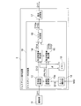
- FIG. 2 is a block diagram showing a configuration of the gesture operating device 1 according to the present embodiment.
- the illustrated gesture operation device 1 includes an imaging unit 11, a gesture determination device 10, and an operation determination unit 17.
- the gesture determination device 10 includes a hand region detection unit 12, a coordinate system setting unit 13, a shape feature amount calculation unit 14, a motion feature amount calculation unit 15, and a gesture determination unit 16.
- the imaging unit 11 images a space including the operation region 4 at a predetermined frame rate, generates a series of frame image data D11 representing a moving image of the space, and uses the generated image data D11 as a hand region detection unit. 12 is output.
- the imaging unit 11 includes, for example, an image sensor or a distance measuring sensor, and outputs images such as a color image, a gray scale image, a binary image, and a distance image.
- the imaging target space is irradiated with near infrared light, the reflected light is acquired by the near infrared image sensor, and the image is output. May be.
- the hand region detection unit 12 detects the operator's hand put in the operation region 4 from the image data D11 given from the imaging unit 11, extracts the hand region Rh on the image, and extracts the extracted hand region Rh.
- Information (hand region information) D12 to be shown is generated.
- the hand region information D12 is image data that is labeled with only the extracted hand region Rh as a high level and the other regions as a low level, for example, a pixel value of a pixel in the hand region Rh is a first value, for example, “1”. And image data in which the pixel values of the pixels in other regions are set to a second value, for example, “0”.
- the hand region detection unit 12 applies a technique such as a pattern recognition method, a background difference method, a skin color extraction method, and an inter-frame difference method to the input image data D11, and the operator's hand in the image. Region Rh is extracted.
- the hand area information D12 generated by the hand area detection unit 12 is supplied to the coordinate system setting unit 13 and the shape feature amount calculation unit 14.
- the coordinate system setting unit 13 determines the origin coordinate of the hand coordinate system in the coordinate system of the captured image (hereinafter simply referred to as “image coordinate system”) and the coordinate system of the image from the hand region information D12 given as an input.
- image coordinate system the coordinate system of the image from the hand region information D12 given as an input.
- the relative angle of the hand coordinate system is determined, and information representing these is output to the shape feature quantity calculator 14 and the motion feature quantity calculator 15 as the hand coordinate system parameter D13.
- the shape feature quantity calculating unit 14 Based on the hand coordinate system parameter D13 given from the coordinate system setting unit 13, the shape feature quantity calculating unit 14 obtains at least one of the fingertip position and the number M of fingers extended from the hand region information D12. It is calculated as a feature amount (shape feature amount) representing the shape of the hand, and information (shape feature amount information) D14 indicating the calculated shape feature amount is output to the motion feature amount calculation unit 15 and the gesture determination unit 16.
- the movement feature quantity calculation unit 15 calculates a feature quantity (hand movement feature quantity) representing the movement of the hand (the entire movement of the hand) based on the hand coordinate system parameter D13 given from the coordinate system setting unit 13.
- the hand movement feature amount information D15h representing the hand movement feature amount is generated, and the hand coordinate system parameter D13 given from the coordinate system setting unit 13 and the shape feature amount information D14 given from the shape feature amount calculation unit 14 Based on this, a feature amount (finger movement feature amount) representing finger movement is calculated, finger movement feature amount information D15f representing finger movement feature amount is generated, and the generated hand movement feature amount information D15h and finger movement feature amount information are generated.
- D15f is output to the gesture determination unit 16.
- the gesture determination unit 16 uses the shape feature value information D14 given from the shape feature value calculation unit 14 and the motion feature value information D15h and D15f given from the motion feature value calculation unit 15 as reference values D14r defined in advance. , D15hr, D15fr, the type of gesture is determined based on the result of the comparison, a parameter related to the gesture is generated, and information D16a indicating the type of gesture and parameter D16b related to the gesture are sent to the operation determination unit 17 Output.
- the operation determination unit 17 generates a command D17 based on the information D16a indicating the type of gesture output from the gesture determination unit 16 and the parameter D16b related to the gesture, and outputs the command D17 to the operation control unit 5.
- the command D17 is an operation instruction for the operated devices 6a, 6b, and 6c, or an instruction for the operation control unit 5 for selection of the operated device performed prior to the operation.
- the operation control unit 5 displays a screen (operation screen) for displaying guidance for selecting an operated device and operating the operated device, and the operator 3 inputs an operation by a gesture in accordance with the guidance on the operation screen. Do.
- the operation input by the gesture is performed by putting the hand in the operation area 4, making the hand a predetermined shape, and moving the entire hand in a predetermined pattern, or moving the finger in a predetermined pattern. Is called.
- the coordinate system setting unit 13 obtains the origin coordinate of the hand coordinate system in the image coordinate system (relative position of the origin of the hand coordinate system with respect to the origin of the image coordinate system) from the hand region information D12 given from the hand region detection unit 12. ) And the relative angle (rotation angle) of the hand coordinate system with respect to the image coordinate system, and information representing them is used as the hand coordinate system parameter D13 to the shape feature value calculation unit 14 and the movement feature value calculation unit 15. Output.
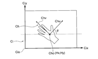
- FIG. 3 shows the relationship between the image coordinate system Ci and the hand coordinate system Ch.
- the image coordinate system Ci is a coordinate system based on an image acquired by the imaging unit 11, and is an orthogonal coordinate system and a right-handed coordinate system.
- the lower left of the image is set as the origin Cio of the image coordinate system Ci
- the horizontal axis Cix is set as the first axis
- the vertical axis Ciy is set as the second axis. be able to.
- the hand coordinate system Ch is a coordinate system based on the hand region Rh in the image, and is an orthogonal coordinate system and a right-handed coordinate system.
- the palm center Po is the origin Cho of the hand coordinate system, and the first axis Chu and the second axis Chv passing through the origin are set.
- FIG. 3 the hand indicated by the hand region Rh is drawn in the same direction as in FIG. This is an image obtained when the hand in the operation area 4 is imaged from above.
- the images obtained by the imaging by the imaging unit 11 are By reversing, the image shown in FIG. 3 is obtained.
- FIG. 3 it demonstrates as what uses the image obtained by performing such right-and-left inversion. This is because by performing such left-right reversal, it is possible to assume an image in which the hand in the operation area 4 is viewed from above, that is, from the same viewpoint as the operator.
- the component of the first axis Cix is represented by x
- the component of the second axis Ciy is represented by y
- the coordinates of each point are represented by (x, y).
- the component of the first axis Chu is u
- the component of the second axis Chv is v
- the coordinates of each point are expressed as (u, v).
- the coordinates of the origin Cho of the hand coordinate system Ch (relative position of the origin of the hand coordinate system with respect to the origin Cio of the image coordinate system) are represented by (Hx, Hy), and the image coordinate system An angle (relative angle) formed by the first axis Chu of the hand coordinate system with respect to the first axis Cix is represented by ⁇ .
- the coordinate system setting unit 13 determines the coordinates (Hx, Hy) of the origin Cho of the hand coordinate system Ch in the image coordinate system Ci, and the direction of the first axis Chu of the hand coordinate system in the image coordinate system Ci. And the direction of the second axis Chv. Specifically, the palm center Po is determined as the origin Cho of the hand coordinate system Ch, and the first axis Chu and the second axis of the hand coordinate system Ch are determined from the vector direction from the wrist center to the palm center. Determine the direction of Chv.
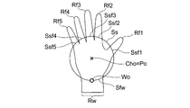
- the coordinate system setting unit 13 calculates a palm feature amount from the hand region information D12. As the feature amount of the palm, as shown in FIG. 4, a palm center Po and a palm radius Pr are calculated.
- the shortest distance to the contour of the hand region Rh is obtained, and the point having the maximum shortest distance is calculated as the coordinates (Hx, Hy) of the palm center Po. Then, the shortest distance from the palm center Po to the contour of the hand region Rh is calculated as the palm radius Pr.
- the method for calculating the center of the palm is not limited to the above-described method.
- the center of the largest square that is within the hand region and that is the largest may be used as the center of the palm.
- the coordinate system setting unit 13 calculates the position of the wrist based on the hand area information D12 and the calculated palm feature (the palm center Po and the radius Pr). Specifically, the coordinate system setting unit 13 first determines the wrist search line Ss for specifying the wrist region from the feature amount of the palm. Next, the wrist region Rw on the search line Ss is specified from the feature value of the wrist thickness, and the center position Wo of the wrist is calculated.
- the coordinate system setting unit 13 searches the area outside the palm based on the hand area information D12, and specifies the wrist area from the difference between the thickness of the finger and the thickness of the wrist. Specifically, in an image including the hand region indicated by the hand region information D12, a circle having a radius ⁇ ⁇ Pr and a radius ⁇ ⁇ Pr is drawn as a search line Ss.
- the search line Ss can be drawn outside the palm by setting the coefficient ⁇ to be multiplied by the palm radius Pr so as to satisfy ⁇ > 1. That is, it is possible to search for a wrist region located outside the palm.
- An image including a hand region is searched along the search line Ss, and an overlap between the search line Ss and the hand region Rh is examined.
- the search line Ss is a set of points having coordinates (x, y) that satisfy the relationship of the following formula (1).
- the search line Ss and the hand area Rh overlap (search line Ss) in the wrist region Rw and the extended finger regions Rf1 to RfM (M is the number of extended fingers), respectively.
- the hand region Rh is crossed).
- the thickness of the wrist is larger than the thickness of the finger
- the length of the portion Ssw that overlaps the wrist region Rw of the search line Ss is larger than the radius Pr of the palm.
- the length of the portion Ssfm that overlaps each finger region Rfm in the search line Ss is smaller than the palm radius Pr.
- the coordinate system setting unit 13 records the length of the search line where the search line Ss and the hand region Rh overlap (the length of the portion of the search line that overlaps the hand region Rh), and for each overlap
- the wrist region is identified by comparing the length of the overlapped search line with the radius of the palm.
- an index i i ⁇ 1,..., N
- the length of the search line of the overlapped portion is set to f [1]. ,..., F [N].
- N indicates the number of portions where the search line Ss and the hand region Rh overlap.
- f [1] F1
- F2 F2
- the “length of the portion of the search line Ss that overlaps the hand region Rh” may be a length along the arc-shaped search line. Instead, the point where the overlap starts and the point where the overlap ends are determined. It is good also as calculating
- a comparison is made with the palm radius, f [i]> ⁇ ⁇ Pr
- a portion that satisfies the condition is identified as a wrist region.
- the coefficient ⁇ multiplied by the palm radius Pr is preferably set to satisfy ⁇ ⁇ 1, and the length of the search line overlapping the hand region Rh is specified to be equal to or larger than the palm radius Pr. be able to.
- the coordinate system setting unit 13 calculates, as coordinates (Wx, Wy) of the wrist center Wo, the midpoint of the search line that overlaps the wrist region specified in this way.
- the circular search line Ss is used.
- the shape of the search line may be any other shape as long as it can search the outside of the palm.
- it may be a polygon, for example, a hexagon or an octagon.
- the coordinate system setting unit 13 sets the palm center coordinates (Hx, Hy) calculated as described above as the origin coordinates of the hand coordinate system in the image coordinate system, and the palm center coordinates (Hx, Hy) and the wrist.
- Directions of the first axis Chu and the second axis Chv of the coordinate system are determined from the center coordinates (Wx, Wy) of the coordinate system.
- the directions of the first axis Chu and the second axis Chv of the hand coordinate system are not limited to the above example, and are determined in an arbitrary direction based on a vector from the wrist center Wo to the palm center Po. good.
- the coordinate system setting unit 13 When the direction of the first axis Chu and the second axis Chv of the hand coordinate system is determined, the coordinate system setting unit 13 outputs information indicating the directions. For example, information indicating the relative angle ⁇ of the hand coordinate system with respect to the image coordinate system is output.
- the relative angle of the hand coordinate system with respect to the image coordinate system for example, an angle formed by the first axis Cix of the image coordinate system and the first axis Chu of the hand coordinate system may be used.
- An angle formed by the second axis Ciy of the coordinate system Ci and the second axis Chv of the hand coordinate system Ch may be used. More generally, an angle formed between one of the first axis Cix and the second axis Ciy of the image coordinate system Ci and one of the first axis Chu and the second axis Chv of the hand coordinate system Ch may be used. .
- the angle formed by the first axis Chu in the hand coordinate system Ch in the counterclockwise direction with respect to the first axis Cix in the image coordinate system Ci is the hand relative to the image coordinate system Ci.
- the information indicating the relative angle ⁇ is output as the hand coordinate system parameter D13 together with the information indicating the origin coordinate (Hx, Hy) of the hand coordinate system in the image coordinate system.
- FIGS. 8A to 8 (c) show examples of hand coordinate systems set at different relative angles to the image coordinate system.
- ⁇ ⁇ 45 °
- ⁇ 0 °
- ⁇ 45 °
- the relative angle ⁇ of the hand coordinate system is determined with reference to the direction of the vector from the wrist center Wo to the palm center Po, so that FIGS. 8A to 8C are different from each other. Is set corresponding to the angle.
- the origin of the hand coordinate system Ch in the image coordinate system Ci is represented by (Hx, Hy), and the relative angle of the first axis Chu of the hand coordinate system Ch to the first axis Cix of the image coordinate system is represented by ⁇ .
- the coordinates (x, y) of each point in the image coordinate system Ci are expressed by the following conversion equations (2A) and ( 2B), the coordinates can be converted to coordinates (u, v) of the hand coordinate system Ch.
- FIG. 9 shows the first axis Chu, the second axis Chv, the finger candidate region Rfc, and fingertip positions Ft1 to FtM of the hand coordinate system Ch.
- the shape feature amount calculation unit 14 obtains at least one of the coordinates representing the position of the fingertip Ftm (m is any one of 1 to M) and the number M of fingers being stretched. It is calculated as a feature value representing the shape (shape feature value).
- the shape feature quantity calculation unit 14 uses an origin coordinate of the hand coordinate system Ch and a parameter D13 indicating the directions of the first axis and the second axis to display an image representing the position of each pixel of the captured image. Convert coordinates in the coordinate system to coordinates in the hand coordinate system. This conversion is performed by the calculations of equations (2A) and (2B).
- the finger that is stretched is identified as follows. First, an area composed of pixels that satisfy a predetermined condition in relation to the coordinate axes Chu and Chv of the hand coordinate system Ch is specified as an area (candidate area) Rfc in which a finger can exist. For example, since the finger is positioned in the positive direction of the second axis Chv of the hand coordinate system Ch from the palm center Po, the coordinate component v in the second axis direction of the hand region Rh satisfies v> 0. A region to be filled is set as a finger candidate region Rfc. In other words, the hand region Rh located in the range of 0 to 180 degrees counterclockwise from the first axis Chu with the origin Cho of the hand coordinate system as the base point is set as the finger candidate region Rfc.
- the shape feature amount calculation unit 14 calculates the coordinates of the fingertip Ftm and the number M of fingers that are stretched for the set finger candidate region Rfc.
- the fingertip Ftm is identified from the contours of the contour of the finger candidate area, and coordinates indicating the position are calculated.
- the distance from the palm center Po is calculated for each contour point of the finger candidate region Rfc.
- each contour point is compared with a distance at a nearby contour point, and a contour point having a larger distance than the contour points on both sides thereof (a contour point having a maximum distance) is specified as a fingertip candidate point Ftcm.
- the distance from the palm center Po to the fingertip Ftm is larger than the palm radius Pr. Therefore, the distance from the palm center Po to the fingertip candidate point Ftmc is defined as Du, Du> ⁇ ⁇ Pr A fingertip candidate point that satisfies the above is specified as the true fingertip Ftm.
- the coordinates of the fingertip candidate point Ftmc are represented by (u, v)
- the distance Du from the palm center Po to the fingertip candidate point Ftmc is obtained by the following equation (3).
- a point where the distance from the palm center Po is larger than the palm radius Pr can be specified as the fingertip Ftm.
- the coordinates of the specified fingertip Ftm in the hand coordinate system Ch are represented by (Fum, Fvm).
- the shape feature quantity calculation unit 14 can also obtain the number of identified fingertips Ftm as the number M of fingers that are stretched.
- the shape feature quantity calculation unit 14 uses at least one of the detected coordinates (Fum, Fvm) of the fingertip Ftm and the number M of fingers extended as a feature quantity (shape feature quantity information) D14 representing the shape of the hand. The result is output to the motion feature amount calculation unit 15 and the gesture determination unit 16.
- the fingertip is identified based on the maximum distance from the center of the palm of each point on the contour line of the hand region Rh, but the present invention is not limited to this.
- the fingertip may be identified using the above method, for example, a pattern matching method, a polygon approximation method, or the like.
- the coordinates of the fingertip may be calculated as coordinates (Fxm, Fym) in the image coordinate system.
- the shape feature quantity calculation unit 14 specifies the finger based on the feature quantity of the hand after limiting the finger candidate area Rfc based on the hand coordinate system. There is a low possibility that the region is mistakenly recognized as a finger.
- the motion feature amount calculator 15 calculates a hand motion feature amount D15h and a finger motion feature amount D15f.
- the hand movement feature amount D15h at least one of the hand speed, the hand acceleration, and the hand movement amount (for example, the movement amount from a certain position (initial position)) is calculated, and the finger movement feature amount is calculated.
- D15f at least one of finger speed, finger acceleration, and finger movement amount (for example, movement amount from a certain position (initial position)) is calculated.
- the speed and amount of movement of these movements are calculated based on the difference in position between at least two different times.
- the acceleration is calculated based on the difference in speed between at least two different times.
- the finger movement characteristic amount D15f may be obtained for each of the extended fingers, or may be obtained only for a representative finger, for example, the third finger.
- the motion feature amount calculation unit 15 obtains the speed, acceleration, and movement amount in the hand coordinate system, and the feature of the finger movement. Calculated as a quantity D15f.
- the change in coordinates is a combination of the component due to finger movement and the component due to hand movement (movement of the entire hand). Is expressed using the coordinates of the hand coordinate system, the change in the coordinates represents only the component due to the movement of the finger. Therefore, by using the coordinates of the fingertip position in the hand coordinate system to calculate the finger speed, finger acceleration, and finger movement, the finger movement with respect to the center of the palm is separated from the overall movement of the hand. Thus, the feature amount D15f of the individual finger movement can be calculated easily and in a short time.
- FIG. 10 shows a change in the coordinate system Ch of the hand when the hand is moved in the operation area 4.
- the coordinate system Ch (t) of the hand at time t has the coordinates of its origin.
- the movement feature amount calculation unit 15 detects, for example, the movement of the center of the palm as the movement of the hand (the movement of the entire hand). Since the hand coordinate system has the palm center as the origin, the movement of the palm center is always zero when expressed in the hand coordinate system. However, the movement of the center of the palm is caused by the component in the direction of the first axis Chu of the hand coordinate system and the component in the direction of the second axis Chv at each time point, that is, the first axis Cix in the image coordinate system Ci. On the other hand, it is advantageous to detect by decomposing into a component in the direction of the relative angle ⁇ and a component in the direction of ⁇ + 90 degrees.
- the components in these directions represent the movement in the direction perpendicular to the straight line connecting the center of the wrist and the center of the palm and the direction of the straight line connecting the center of the wrist and the center of the palm, respectively.
- the position of the center of the palm at a certain point in time is set as the starting point, and
- the movement amount p is calculated by integrating the movement amount per minute time in the direction of the angle ⁇ (movement amount between successive frames) ⁇ p, and the movement amount ⁇ q per minute time in the direction of the relative angle ⁇ + 90 degrees. Is added to calculate the movement amount q.
- the movement amounts p and q obtained in this way are referred to as “movement amounts in the direction of the first axis Chu (t) and the second axis Chv (t) of the hand coordinate system Ch (t) at each time point”.
- the amount of movement per unit time is referred to as speed
- the change in speed per unit time is referred to as acceleration.
- the movement amounts p and q are obtained as follows. As shown in FIG. 10, when the origin and relative angle of the hand coordinates at time t and time t + ⁇ t change as shown in FIG. 10, the movements ⁇ p and ⁇ q during the time ⁇ t are shown in FIG. Therefore, the following formula is given.
- reference numerals 111 and 112 denote line segments that pass through the origins of coordinates Cho (t) and Cho (t + ⁇ t) and are parallel to the axis Cix.
- ⁇ (t) is an angle formed by the direction of the first axis Chu of the hand coordinate system and the direction of movement of the origin, and is given by the following equation (8).
- ⁇ (t) is an angle formed by the direction of movement of the origin of the hand coordinate system and the first axis Cix of the image coordinate system, and is given by Expression (9) below.
- the movement amount p gradually increases with time, while the movement amount q maintains zero. Even if the movement is not a perfect circular movement but a little deviated from it, the movement amount q is close to zero.
- the moving amount q gradually increases with time, while the moving amount p maintains zero. Even if the movement is not a complete linear movement but a little deviated from the movement, the movement amount p is close to zero.
- the angle ⁇ shown in FIG. 10 is kept constant or substantially constant. Even in directions other than the above, the angle ⁇ is kept substantially constant when movement in a direction that forms a constant or substantially constant angle with respect to the straight line connecting the wrist and the palm is continued.
- the value of the movement amount p or the movement amount q is zero or a value close thereto, or the angle ⁇ is substantially constant. It becomes easy to specify the feature amount of the movement.
- the amount of change in the center position of the palm is detected as the feature amount D15h of the hand movement.
- the present invention is not limited to this.
- the amount of change in the center of gravity of the hand region Rh is Alternatively, the amount of change in the position of another part of the hand may be used as the feature amount D15h of the hand movement.
- the movement feature amount calculation unit 15 converts each coordinate component in the image coordinate system into a coordinate component in the hand coordinate system and calculates the finger movement feature amount D15f regarding the finger movement. To the gesture determination unit 16. Further, the motion feature amount calculation unit 15 relates to the movement of the hand, the component of each coordinate in the image coordinate system, the component of the coordinate of the hand coordinate system at each time point, that is, a straight line connecting the center of the wrist and the center of the palm.
- the gesture determination unit 16 determines the type of gesture based on the feature amount of the hand shape input from the shape feature amount calculation unit 14 and the motion feature amounts D15h and D15f input from the motion feature amount calculation unit 15. Then, the information D16a indicating the determination result is output to the operation determining unit 17, the feature amount of the gesture is calculated, and the information indicating the calculated feature amount is output to the operation determining unit 17 as the parameter D16b related to the gesture.
- gestures include hand shapes such as “goo”, “choki”, “par”, hand movements such as hand movements, finger movements such as pinching the dial with fingertips, or A combination of hand shape and hand or finger movement can be mentioned.
- conditions to be satisfied by the shape feature amount and / or the motion feature amount are defined in advance, and are stored in a memory, for example, the gesture determination unit 16.
- the shape feature amount and motion feature calculated by the shape feature amount calculation unit 14 and the motion feature amount calculation unit 15 based on the image data D11 output from the imaging unit 11 during the gesture determination operation are stored in the memory 16m.
- the gesture is recognized based on the determination result.
- the feature amount of the gesture include the coordinates of the fingertip when the shape of the hand is determined, the time during which a specific hand shape is maintained, and the speed of the hand when a hand gesture is determined.
- gesture determination based on hand shape will be described.
- a certain type for certain operation input
- a certain type for certain operation input
- it is defined in advance as a condition that should satisfy “a state where a predetermined number M of fingers are extended for a predetermined time Ts or longer” and is stored in the memory 16m.
- the gesture determination unit 16 determines that the certain kind of gesture has been performed.
- a state in which the number M of fingers extended as the feature amount of the hand shape is two continues for a predetermined time Ts. This is stored in the memory 16m as a condition that should be satisfied.
- the number M of fingers extending as the feature amount of the hand shape calculated by the shape feature amount calculation unit 14 with respect to the image data D11 output from the imaging unit 11 is two.
- the gesture determination unit 16 determines that the “choke” gesture has been performed.
- the time Ts is too short, it becomes sensitive to the shape of the hand indicated by the operator, and therefore there is a high possibility that an operation that is not intended for the operator's operation input is erroneously recognized as a gesture for the operation input. .
- the longer the time Ts the longer it takes to recognize the gesture, and the responsiveness becomes worse.
- the time Ts is determined in consideration of these, and is set to 0.3 seconds, for example.
- gesture determination based on hand or finger movement will be described.
- a direction that forms a certain angle with respect to a straight line connecting the center of the wrist and the center of the palm that is, the coordinate axis of the hand coordinate system at each time point
- the speed of the movement, the time during which the movement is continued, or the movement amount in the direction forming the specific angle is When a predetermined condition is satisfied (for example, when the movement of the hand in a specific direction of the hand coordinate system at each time point is continued at a speed within a predetermined range for a predetermined time or more), It is determined that a gesture (a gesture for inputting an operation) is performed.
- a direction forming a specific angle with respect to a straight line connecting the center of the wrist and the center of the palm that is, relative to the coordinate axes (Chu, Chv) of the hand coordinate system at each time point.
- the motion speed, the time during which the motion is continued, or the amount of movement in the specific angle is defined in advance as a condition to be satisfied, and the memory 16m Remember me.
- a motion of shaking the hand to the right is a kind of gesture
- the center of the wrist in the image coordinate system In a direction within a range of 90 degrees ⁇ ⁇ degrees ( ⁇ is a predetermined allowable width) with respect to a straight line connecting the center of the palm and the palm center (that is, ⁇ about the first axis Chu of the hand coordinate system at each time point)
- a motion at a speed equal to or higher than the threshold Vuth is defined in advance as a condition that should be satisfied for a certain period of time Td or longer, and is stored in the memory 16m.
- the time Td is determined in consideration of these, and is set to 0.2 seconds, for example.
- the gesture type D16a determined by the gesture determination unit 16 and the parameter D16b related to the gesture are output to the operation determination unit 17.
- the operation determining unit 17 operates the operation content (operation type and / or operation) on the operation control unit 5 or the operated devices 6a, 6b, and 6c from the gesture type D16a input from the gesture determination unit 16 and the parameter D16b related to the gesture. Amount).
- the gesture of “Goo” is a switching operation to “Map guidance screen”
- the gesture of “Choki” is a switching operation to “Audio screen”
- the gesture of “Par” is “Adjustment of air conditioner” It is associated with the switching operation to “screen”.
- Map guidance screen means an initial screen for map guidance
- audio screen means an initial screen for operating an audio function
- air conditioner adjustment screen means an initial screen for operating an air conditioner.
- the operation determination unit 17 changes the display content of the display unit 5 a to “ A command for switching to the “map guidance screen” is generated and output to the operation control unit 5. Further, when the determination result that the gesture of “choki” is performed is input to the operation determination unit 17, the operation determination unit 17 generates a command for switching the display content of the display unit 5a to “audio screen”, Output to the operation control unit 5. When the determination result that the “par” gesture is performed is input to the operation determination unit 17, the operation determination unit 17 generates a command for switching the display content of the display unit 5 a to the “air conditioner adjustment screen”. To the operation control unit 5.
- the display contents of the display unit 5a of the operation control unit 5 can be sequentially switched using the hand shape and the feature amount of the gesture.
- the “goo” gesture is associated with the switching of the display content, and whenever the “goo” gesture is maintained for a predetermined time, the display selected when the “goo” gesture is terminated at that time.
- the contents (operation screen) are switched cyclically, for example, in a predetermined order.
- the display content of the display unit 5 a is “map guidance screen”, “audio screen”, “air conditioner adjustment screen”, etc. It is configured to switch at a constant interval Tm seconds. While the “goo” gesture is maintained, the operation screen to be selected when the “goo” gesture is terminated at each time point is displayed at each time point. This display can be performed using part or all of the display screen of the display unit 5a.
- a screen having the same content as the selected operation screen is displayed as a candidate, and if the “Goo” gesture is terminated at that time, the displayed candidate screen is operated. It is good also as confirming as a screen.
- time Tm is determined in consideration of these, and is set to 1.0 seconds, for example.
- the movement of the hand which is the type of gesture, and the feature amount of the movement are previously associated with the direction of scrolling the map, the speed of scrolling, etc., and the correspondence relationship is stored in a memory, for example,
- the data is stored in the memory 17m in the operation determination unit 17.
- the type of gesture an action of shaking the hand to the left corresponds to scrolling leftward
- an action of shaking the hand to the right corresponds to scrolling rightward. That is, the direction of scrolling is associated with the direction of waving.
- the speed of waving is made to correspond to the speed of scrolling.
- the operation determination unit 17 A command for scrolling the map in the left direction at a speed corresponding to the speed of waving is generated and output to the map guidance device 6 a via the operation control unit 5.
- the operation determination unit 17 moves the map to the right.
- a command for scrolling at a speed corresponding to the speed of waving is generated and output to the map guidance device 6a via the operation control unit 5.
- the operation determination unit 17 outputs a command corresponding to the type of gesture and the feature amount of the gesture to the operation control unit 5 or the operated devices 6a, 6b, and 6c based on the output of the gesture determination unit 16.
- the operation determination unit 17 may be configured to output a command for a gesture based on a combination of a hand shape and a hand or finger movement.
- the procedure of the process in the method (gesture operation method) implemented by the gesture operation apparatus 1 of Embodiment 1 is demonstrated using the flowchart of FIG. First, the imaging unit 11 images a space including the operation region 4 and generates an image of the space (ST1).
- the hand region detection unit 12 detects the hand region Rh of the operator put in the operation region 4 from the image given as an input from the imaging unit 11, and generates hand region information D12 (ST2).
- the hand area information D12 generated in step ST2 is sent to the coordinate system setting unit 13 and the shape feature amount calculation unit 14.
- step ST3 the coordinate system setting unit 13 sets the hand coordinate system based on the hand area information D12 generated in step ST2, and calculates the origin coordinate and the relative angle of the hand coordinate system.
- the origin coordinate and the relative angle of the hand coordinate system calculated in step ST3 are sent from the coordinate system setting unit 13 to the shape feature value calculating unit 14 and the motion feature value calculating unit 15 as parameters of the hand coordinate system.
- step ST4 the shape feature quantity calculation unit 14 calculates the shape feature quantity D14 from the hand region information D12 output in step ST2 and the origin coordinate and relative angle of the coordinate system calculated in step ST3.
- Information representing the shape feature amount (shape feature amount information) D ⁇ b> 14 is sent to the motion feature amount calculation unit 15 and the gesture determination unit 16.
- step ST5 the motion feature amount calculation unit 15 calculates the hand motion feature amount and the finger position from the origin coordinates and relative angle of the coordinate system calculated in step ST3 and the shape feature amount information D14 calculated in step ST4.
- the movement feature amount is calculated, and information D15h and D15f representing the movement feature amount is sent to the gesture determination unit 16.
- step ST6 the gesture determination unit 16 determines the type of gesture from the shape feature amount information D14 calculated in step ST4 and the motion feature amounts D15h and D15f calculated in step ST5, and determines the gesture feature amount.
- the calculated information D16a indicating the type of gesture and the parameter D16b related to the gesture are sent to the operation determining unit 17.
- step ST7 the operation determination unit 17 determines the operation content from the type of gesture determined in step ST6 and the feature amount of the gesture, and sends a command indicating the operation content to the operation control unit 5 or the operated devices 6a and 6b. , 6c, and finishes.
- the coordinate system setting unit 13 sets the hand coordinate system, and based on the hand coordinate system, the feature amount of the hand shape and the hand and finger For example, the feature amount of the hand shape in the hand coordinate system and the feature amount of the finger movement are calculated, and the hand in the specific direction of the hand coordinate system at each time point is calculated.
- the feature amount of the movement it is possible to accurately reduce the misrecognition without being affected by the difference in the angle of the hand in the operation area 4 or the difference in the direction of the movement such as the hand movement motion, which is different for each operator. Gesture determination is possible.
- the center of the palm is determined as the origin of the hand coordinate system, and the direction of the axis of the hand coordinate system is determined from the direction vector from the center of the wrist to the center of the palm. Even when a hand is put in the operation area, the hand coordinate system can be set accurately.
- the shape feature amount calculation unit 14 specifies a part satisfying a predetermined condition based on the hand coordinate system in the hand region Rh indicated by the hand region information D12 as the finger candidate region Rfc, and specifies Since the position of the fingertip is detected and the feature amount (shape feature amount) representing the shape of the hand is calculated in the finger candidate region Rfc, the finger candidate region is narrowed down based on the hand coordinate system.
- the shape feature amount can be calculated, the possibility of misrecognizing a region other than a finger as a finger is reduced, and the amount of calculation can be reduced compared to a case where candidate regions are not narrowed down.
- the motion feature quantity calculation unit 15 calculates the feature quantities D15h and D15f of the hand and finger movements based on the hand coordinate system.
- the motion feature quantity D15f is the coordinate in the hand coordinate system.
- the feature quantity D15h of the hand movement is calculated based on the direction of the coordinate axis of the hand coordinate system at each time point or the movement in a specific direction with respect to the coordinate axis. The feature amount can be stably obtained without being influenced by the difference in the direction of movement such as the angle of the hand in the operation region 4 and the hand movement motion.
- the gesture determination unit 16 also includes, for example, a feature amount D14 of the hand shape and a feature amount D15f of the finger movement in the hand coordinate system, and a feature amount of the hand movement in a specific direction of the hand coordinate system at each time point. Based on D15h, by determining the type of gesture and calculating the feature amount of the gesture, it is possible to perform gesture determination with less misrecognition without being affected by the difference in the direction of hand movement in the image coordinate system. is there.
- the gesture operation device 1 Since the gesture operation device 1 according to the present embodiment operates using the determination result obtained by the gesture determination device 10 having the above-described effect, it can perform an accurate operation based on the accurate determination result.
- the motion feature amount calculation unit 15 calculates both the hand motion feature amount information D15h and the finger motion feature amount information D15f, but the motion feature amount calculation unit 15 performs the hand motion feature amount information D15h. Or only one of the finger movement feature amount information D15f may be calculated.
- FIG. FIG. 14 is a block diagram showing a configuration of a gesture operating device according to Embodiment 2 of the present invention.
- the gesture operation device shown in FIG. 14 is generally the same as the gesture operation device shown in FIG. 2, and the same reference numerals as those in FIG. 2 denote the same or corresponding parts, but a mode control unit 18 and a memory 19 are added.
- the difference is that a coordinate system setting unit 13a is provided instead of the coordinate system setting unit 13 shown in FIG.
- the mode control unit 18 is given mode selection information MSI from the outside, and outputs the mode control information D18 to the coordinate system setting unit 13a.
- the coordinate system setting unit 13a is provided with hand region information D12 from the hand region detection unit 12, is provided with mode control information D18 from the mode control unit 18, and includes a hand based on the hand region information D12 and the mode control information D18. Parameters of the hand coordinate system Ch are calculated from the image of the operation area. On the other hand, when the coordinate system setting mode is selected by the mode control information D18, a part of the parameters of the coordinate system, for example, a relative angle is calculated, and the calculated relative angle ⁇ is stored in the memory 19.
- the coordinate system setting unit 13a based on the hand region information D12 from the hand region detecting unit 12, for example, the remaining part of the coordinate system parameters, The origin coordinates (Hx, Hy) are calculated, and the calculated origin coordinates (Hx, Hy) are output to the shape feature quantity calculator 14 and the motion feature quantity calculator 15.
- the memory 19 receives and stores information representing the relative angle of the hand coordinate system with respect to the coordinate system of the image from the coordinate system setting unit 13a.
- the relative angle ⁇ stored in the memory 19 is read and supplied to the shape feature amount calculator 14 and the motion feature amount calculator 15.
- the shape feature amount calculation unit 14 is provided with hand region information D12 from the hand region detection unit 12, and is provided with information indicating the origin coordinates (Hx, Hy) of the hand coordinate system from the coordinate system setting unit 13a. Information indicating the relative angle ⁇ of the hand coordinate system with respect to the image coordinate system is given, and the shape feature amount is calculated based on the information, and is output to the motion feature amount calculation unit 15 and the gesture determination unit 16.
- the motion feature amount calculation unit 15 is provided with hand region information D12 from the hand region detection unit 12, and is provided with information indicating the origin coordinates (Hx, Hy) of the hand coordinate system from the coordinate system setting unit 13a. Information indicating the relative angle ⁇ of the hand coordinate system with respect to the image coordinate system is given, and based on these, motion feature values D15h and D15f are calculated and output to the gesture determination unit 16.
- the mode control unit 18 generates mode control information D18 based on the mode selection information MSI input from the outside, and outputs the mode control information D18 to the coordinate system setting unit 13a.
- the mode selection information MSI is information relating to the selection of the coordinate system setting mode given from the outside, for example, mode designation information indicating whether the coordinate system setting mode should be selected or the feature amount calculation mode should be selected.
- the mode control information D18 is generated based on the mode selection information MSI given from the outside. For example, when the coordinate system setting mode is selected, a first value, for example, “0” is output, When the amount calculation mode is selected, a second value, for example, “1” is output.
- the mode control unit 18 receives the switching information (a) to (c), determines which mode should be operated at each time point, and outputs mode control information D18 based on the determination result.
- the coordinate system setting unit 13a switches the processing content based on the mode control information D18 given from the mode control unit 18.
- the coordinate system setting unit 13a relates to the coordinate system setting unit 13 in the first embodiment.
- the relative angle of the hand coordinate system is calculated from the hand region information D12, and the relative angle of the hand coordinate system with respect to the image coordinate system is output to the memory 19.
- the coordinate system setting unit 13a is the coordinate system setting unit in the first embodiment. 13 the origin coordinate (Hx, Hy) of the hand coordinate system is calculated from the hand region information D12 (while the relative angle ⁇ is not calculated), and the shape feature quantity calculation unit 14 and the motion are calculated.
- the data is output to the feature amount calculation unit 15.
- FIG. 15 is generally the same as the method shown in FIG. 13, except that steps ST11 to ST13 are added and steps ST14, ST4a, and ST5a are included instead of steps ST3 to ST5.
- steps ST11 to ST13 are added and steps ST14, ST4a, and ST5a are included instead of steps ST3 to ST5.
- steps ST14, ST4a, and ST5a are included instead of steps ST3 to ST5.
- steps ST14, ST4a, and ST5a are included instead of steps ST3 to ST5.
- FIG. 15 the same reference numerals as those in FIG. 13 denote the same or corresponding steps.
- the mode control unit 18 determines whether or not the coordinate system setting mode is selected in step ST11. This determination is made based on the mode selection information MSI. When the coordinate system setting mode is selected, the mode control unit 18 notifies the coordinate system setting unit 13a to that effect, and in step ST12, the coordinate system setting unit 13a determines from the hand region information D12 output in step ST12. Sets the relative angle of the hand coordinate system to the image coordinate system. In step ST13, the coordinate system setting unit 13a stores the relative angle of the hand coordinate system output in step ST12 in the memory 19, and ends the process.
- step ST11 If it is determined in step ST11 that the operator has selected the feature amount calculation mode, the mode control unit 18 notifies the coordinate system setting unit 13a to that effect, and in step ST14, the coordinate system setting unit 13a performs step ST2.
- the origin coordinate (Hx, Hy) of the hand coordinate system is calculated and set from the hand region information D12 output in step S12, and is output to the shape feature amount calculator 14 and the motion feature amount calculator 15.
- step ST4a the shape feature quantity calculating unit 14 outputs the hand region information D12 output in step ST2, the relative angle ⁇ of the hand coordinate system with respect to the coordinate system of the image stored in the memory 19, and step ST14.
- the shape feature amount is calculated from the origin coordinates (Hx, Hy) of the hand coordinate system set in step S14, and information (shape feature amount information) D14 indicating the calculated shape feature amount is used as the motion feature amount calculation unit 15 and the gesture determination.
- step ST5a the motion feature amount calculation unit 15 calculates the relative angle ⁇ of the hand coordinate system with respect to the image coordinate system stored in the memory 19, and the origin coordinate (Hx, Hy), a hand motion feature amount D15h and a finger motion feature amount D15f are calculated, and the calculated motion feature amounts D15h and D15f are output to the gesture determination unit 16.
- step ST6 the gesture determination unit 16 determines the type of gesture from the shape feature amount calculated in step ST4a and the motion feature amounts D15h and D15f calculated in step ST5a, and generates a parameter related to the gesture.
- the gesture type may be determined using only one of the hand movement feature amount and the finger movement feature amount as the movement feature amount, as described in the first embodiment.
- the gesture determination device 10 and the gesture operation device 1 have the memory 19, the relative angle ⁇ of the hand coordinate system can be stored.
- the configuration has the mode control unit 18, either the mode for storing the relative angle ⁇ of the hand coordinate system or the mode for calculating the feature amount using the stored relative angle ⁇ is selected. can do.
- the processing is performed on the assumption that the relative angle ⁇ of the hand coordinate system changes with the hand movement operation, whereas in the second embodiment, the coordinate system setting mode is selected. If not, that is, if the feature amount calculation mode is selected, the processing is performed assuming that the relative angle ⁇ is constant.
- the origin coordinate of the hand coordinate system changes each time the operator enters the operation area 4, but the hand relative to the coordinate system of the image changes.
- the relative angle of the coordinate system does not change greatly.
- even in the case of a hand gesture operation if the rotation angle of the hand gesture is small, the relative angle ⁇ does not change greatly. Therefore, even if it is constant, the gesture can be determined with sufficiently high accuracy.
- the coordinate system setting unit 13a calculates the relative angle ⁇ of the hand coordinate system with respect to the coordinate system of the image, and calculates the calculated relative angle ⁇ . It is stored in the memory 19.
- the coordinate system setting unit 13a calculates only the origin coordinate of the hand coordinate system, and information indicating the relative angle ⁇ of the hand coordinate system, that is, the first axis and the first axis. Information indicating the directions of the two axes is read from the memory 19 and used.
- the gesture operation can be realized with such a small amount of calculation, it is possible to speed up the process from the gesture operation by the operator until the gesture operation device performs the gesture determination and generates the command to the device. That is, the responsiveness of the device to the operation of the operator can be improved, and the usability of the operator can be improved.
- gesture determination and gesture operation can be realized with a small amount of calculation, it can be implemented with a low-cost processing device with low processing capability, and the cost of the device can be reduced.
- the mode control unit 18 controls the operation of the coordinate system setting unit 13a based on the mode selection information MSI.
- the relative angle of the hand coordinate system with respect to the image coordinate system can be set at an arbitrary timing and stored in the memory 19.
- the relative angle of the hand coordinate system with respect to the image coordinate system is set only once, and information indicating the relative angle is continuously used. be able to.
- the relative angle of the hand coordinate system with respect to the image coordinate system can be set and stored in the memory 19 for use. it can. That is, even when the operator changes, gesture determination and gesture operation can be performed with a small amount of calculation.
- the mode selection information MSI may be input by the operator using the gesture operation device of the present invention or another operation input device, and is set in the coordinate system when the operator starts to use the gesture operation device. After the mode is automatically selected and information indicating the relative angle of the hand coordinate system to the image coordinate system is stored in the memory 19, the selection of the coordinate system setting mode may be automatically canceled. In addition, it automatically switches between selecting the coordinate system setting mode and selecting the feature amount calculation mode periodically or when some condition is met. Each time the relative angle of the system is calculated, the stored content of the memory 19 (the stored relative angle of the hand coordinate system) may be updated.
- the present invention is not limited to this, and the parameter stored in the memory 19 is not limited thereto.
- the feature amount calculation mode a part of the parameters of the coordinate system is stored, and the stored parameters may be read out and used to calculate the shape feature amount and the motion feature amount.
- the calculation load can be reduced.
- FIG. FIG. 16 is a block diagram showing the configuration of the gesture operating device according to Embodiment 3 of the present invention.
- the gesture operation device shown in FIG. 16 is generally the same as the gesture operation device shown in FIG. 2, and the same reference numerals as those in FIG. 2 denote the same or corresponding parts.
- the gesture operation device shown in FIG. 16 is generally the same as the gesture operation device shown in FIG. 2 except that an operator estimation unit 20 is added and an operation determination unit 17 a is provided instead of the operation determination unit 17. It is different.
- the operator estimation unit 20 estimates the operator based on one or both of the origin coordinate and the relative angle of the hand coordinate system output by the coordinate system setting unit 13, and outputs the operator information D20 to the operation determination unit 17a.
- the estimation of the operator here may be, for example, estimation of which seat the operating person is seated on or estimation of which person is operating. In the former case, for example, an identification number corresponding to the seat is operator information, and in the latter case, for example, person identification information is operator information.
- the operator estimation unit 20 specifies the position of the operator from one or both of the origin coordinate and the relative angle of the hand coordinate system, and generates operator information.
- the position of the operator can be specified from the direction of the axis of the hand coordinate system.
- the coordinate system setting unit 13 sets the second axis Chv of the hand coordinate system in the same direction as the vector from the wrist center to the palm center
- the relative angle ⁇ of the hand coordinate system with respect to the image coordinate system is ⁇ If the angle is between 90 degrees and 0 degrees, the operator is assumed to be located in the lower left direction from the center of the image. If ⁇ is between 0 ° and 90 °, the operator is assumed to be located in the lower right direction from the center of the image. In this case as well, as described in the first embodiment, it is assumed that an image when the hand in the operation area 4 is imaged from above is obtained.
- the operator information can be determined by associating the estimated operator position with the seat position. Also, the operator information can be determined by associating the position of the operator with a specific person.
- the operation determination unit 17a is based on information D16a indicating the type of gesture output from the gesture determination unit 16, a parameter D16b related to the gesture, and operator information D20 output from the operator estimation unit 20. 5 or commands to the operated devices 6a, 6b, 6c are determined and output.
- FIG. 17 is generally the same as the method shown in FIG. 13, but differs in that step ST21 is added and step ST7a is included instead of step ST7.
- step ST21 is added and step ST7a is included instead of step ST7.
- step ST7a is included instead of step ST7.
- FIG. 17 the same reference numerals as those in FIG. 13 denote the same or corresponding steps.
- step ST21 the operator estimation unit 20 estimates the operator based on one or both of the origin coordinate and the relative angle of the hand coordinate system set in step S3, and outputs the estimation result to the operation determination unit 17a.
- step ST7a the operation determination unit 17a obtains the operation content from the information D16a indicating the type of gesture determined in step ST6, the parameter D16b related to the gesture, and the operator information D20 generated by the estimation in step ST21.
- a command to be generated is generated and output to the operation control unit 5 or the operated devices 6a, 6b, and 6c, and the process ends.
- the gesture operation device includes the operator estimation unit 20, even when the same gesture is performed in the operation region 4, the operation content ( The type of operation and / or the operation amount) can be changed.
- “Chioki” means selection of “audio screen”, while in other operators, “gesture with only one finger extended” is “audio screen” It may also mean selection, and the speed of movement or the duration of the same gesture (the time during which the same shape is maintained, the time during which the same movement is continued) can be set differently depending on the operator.
- the image coordinate system and the hand coordinate system are the orthogonal coordinate system and the right hand coordinate system, but the present invention is not limited to a specific type of coordinate system.
- the origin coordinate and the relative angle of the hand coordinate system are used as parameters of the hand coordinate system.
- the present invention is not limited to this, and the origin coordinate of the hand coordinate system and the first coordinate from the coordinate system of the image. Any parameter that can specify the direction of the axis and the second axis may be used.
- the coordinate system setting unit 13 sets the two coordinate axes Chu and Chv.
- the present invention is not limited to this, and the number of set coordinate axes may be one or three or more. But you can. In short, at least one coordinate axis may be set.
- gesture determination is performed based on the feature amount of the shape calculated by the shape feature amount calculation unit 14 and the feature amount of the hand movement or the finger movement calculated by the movement feature amount calculation unit 15. However, the gesture determination may be performed based on only the feature amount of the hand movement without using the shape feature amount and the feature amount of the finger movement. In the following, a configuration in which only one coordinate axis is set in the hand coordinate system and gesture determination is performed based only on the feature amount of the hand movement will be described.
- FIG. 18 is a block diagram showing the configuration of the gesture operating device according to the fourth embodiment of the present invention.
- the gesture operating device shown in FIG. 18 is generally the same as the gesture operating device shown in FIG. 2, and the same reference numerals as those in FIG. 2 denote the same or corresponding parts, but the shape feature quantity calculating unit 14 shown in FIG.
- the coordinate system setting unit 13 b is provided instead of the coordinate system setting unit 13, the motion feature amount calculating unit 15 b is provided instead of the motion feature amount calculating unit 15, and the gesture determining unit 16 Instead, the difference is that a gesture determination unit 16b is provided.
- the coordinate system setting unit 13b determines the origin coordinates of the hand coordinate system in the image coordinate system and the relative angle of the hand coordinate system with respect to the image coordinate system from the hand region information D12 given as an input, and represents them.
- the information is output to the motion feature amount calculation unit 15b as a hand coordinate system parameter D13b.
- the movement feature amount calculation unit 15b calculates a feature amount (hand movement feature amount) of the hand movement (total movement of the hand) based on the hand coordinate system parameter D13b given from the coordinate system setting unit 13b.
- Information (hand movement feature amount information) D15h indicating the calculated hand movement feature amount is generated and output to the gesture determination unit 16b.
- the gesture determination unit 16b collates the hand movement feature amount information D15h given from the movement feature amount calculation unit 15b with a reference value D15hr defined in advance, determines the type of gesture based on the result of the collation, Such parameters are generated, and information D16a indicating the type of gesture and parameter D16b related to the gesture are output to the operation determination unit 17.
- the operations of the hand region detection unit 12 and the operation determination unit 17 are the same as those described in the first embodiment.
- operations of the coordinate system setting unit 13b, the motion feature amount calculation unit 15b, and the gesture determination unit 16b will be described in more detail.
- the coordinate system setting unit 13b calculates the origin coordinate of the hand coordinate system in the image coordinate system (the relative position of the origin of the hand coordinate system with respect to the origin of the image coordinate system) from the hand region information D12 given from the hand region detection unit 12. ) And the relative angle (rotation angle) of the hand coordinate system with respect to the image coordinate system, and information representing them is output to the motion feature amount calculation unit 15b as the hand coordinate system parameter D13b.
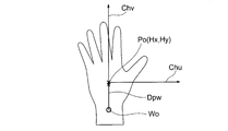
- FIG. 19 shows the relationship between the image coordinate system Ci and the hand coordinate system Ch. As shown in the figure, only one coordinate axis Chu is set in the hand coordinate system.
- the coordinate system setting unit 13b determines the coordinates (Hx, Hy) of the origin Cho of the hand coordinate system Ch in the image coordinate system Ci in the same manner as described in the first embodiment, and also the image coordinate system.
- the direction of the coordinate axis Chu of the hand coordinate system at Ci is determined.
- the direction of the vector perpendicular to the vector Dpw from the wrist center Wo to the palm center Po is determined as the direction of the coordinate axis Chu of the hand coordinate system.
- the direction of the coordinate axis Chu of the hand coordinate system is not limited to the above example, and may be determined in any direction based on a vector from the wrist center Wo to the palm center Po.
- the reference vector is not limited to the vector from the wrist center Wo to the palm center Po, but may be a vector connecting any two points of the hand.
- the coordinate system setting unit 13b When the direction of the coordinate axis Chu of the hand coordinate system is determined, the coordinate system setting unit 13b outputs information indicating the direction. For example, information indicating the relative angle ⁇ of the hand coordinate system with respect to the image coordinate system is output.
- the relative angle of the hand coordinate system with respect to the image coordinate system for example, an angle formed by the first axis Cix of the image coordinate system and the coordinate axis Chu of the hand coordinate system may be used.
- An angle formed between the second axis Ciy of the system Ci and the coordinate axis Chu of the hand coordinate system Ch may be used.
- the angle formed by the hand coordinate system Chu in the counterclockwise direction with respect to the first axis of the image coordinate system is used as the relative angle ⁇ of the hand coordinate system Ch with respect to the image coordinate system Ci.
- the information indicating the relative angle ⁇ is output as the hand coordinate system parameter D13b together with the information indicating the origin coordinates (Hx, Hy) of the hand coordinate system in the image coordinate system.
- the movement feature amount calculation unit 15b calculates a feature amount D15h of hand movement.
- the hand movement feature amount D15h at least one of the hand speed, the hand acceleration, and the hand movement amount (for example, the movement amount from a certain position (initial position)) is calculated.
- the speed and amount of movement of these movements are calculated based on the difference in position between at least two different times.
- the acceleration is calculated based on the difference in speed between at least two different times.
- the movement feature amount calculation unit 15b detects, for example, the movement of the center of the palm as the movement of the hand (the movement of the entire hand).
- the movement of the hand is advantageously detected based on the direction component of the coordinate axis of the hand coordinate system.
- the operator moves the hand based on the above direction of his / her hand rather than using the direction of the image generated by the imaging unit 11 (the direction of the imaging surface of the imaging unit 11) as a reference. This is because the direction is easily recognized and controlled.
- a movement amount r in a direction that forms a specific angle ⁇ with respect to the coordinate axis of the hand coordinate system is calculated, and a hand movement feature amount D15h is calculated based on the movement amount r.
- the amount of movement r is calculated by integrating the amount of movement ⁇ r per minute time (image acquisition period) in a direction that forms a specific angle ⁇ with respect to the coordinate axis Chu.
- the movement amount r thus obtained is referred to as “a movement amount in a direction that forms an angle ⁇ of the hand coordinate system Ch (t) at each time point”.
- the amount of movement per unit time is referred to as speed, and the change in speed per unit time is referred to as acceleration.
- the movement amount r is obtained as follows in the same manner as described for the movement amounts p and q in the first embodiment. As shown in FIG. 20, when the origin and relative angle of the hand coordinates at time t and time t + ⁇ t change as shown in FIG. 20, the movement ⁇ r during the time ⁇ t has the relationship shown in FIG. Is given by the following equation.
- Equation (10) By accumulating ⁇ r shown in Equation (10), the amount of movement r in the direction of ⁇ at each time point can be obtained.
- the amount of change in the center position of the palm is detected as the feature amount D15h of the hand movement.
- the present invention is not limited to this.
- the amount of change in the center of gravity of the hand region Rh is Alternatively, the amount of change in the position of another part of the hand may be used as the feature amount D15h of the hand movement.
- a plurality of angles ⁇ may be prepared.
- At least one of the quantity, the speed, and the acceleration is calculated as the movement feature quantity D15h.
- the movement feature amount calculation unit 15b converts the component of each coordinate in the image coordinate system into a component in a direction that forms a specific angle with respect to the coordinate system of the hand at each time point with respect to the movement of the hand, Using the converted data, a motion feature amount D15h is calculated, and the calculation result is output to the gesture determination unit 16b. As described above, the movement feature amount calculation unit 15b outputs information indicating the specific angle ⁇ or ⁇ k to the gesture determination unit 16b together with the component in the direction that forms the specific angle ⁇ or ⁇ k with respect to the movement of the hand.
- the gesture determination unit 16b determines the type of gesture based on the movement of the hand based on the motion feature amount input from the motion feature amount calculation unit 15b and outputs information D16a indicating the determination result to the operation determination unit 17.
- the feature amount of the gesture is calculated, and information representing the calculated feature amount is output to the operation determining unit 17 as the parameter D16b related to the gesture.
- gesture determination based on hand movement for example, in a coordinate system of an image, a direction forming a certain angle with respect to a straight line connecting the center of the wrist and the center of the palm (that is, the coordinate axis Chu of the hand coordinate system at each time point)
- the speed of the movement, the time during which the movement is continued, or the amount of movement in the above certain angle satisfies the predetermined condition.
- a certain type of gesture for a certain operation input
- a direction that forms a specific angle with respect to a straight line connecting the center of the wrist and the center of the palm that is, a specific direction relative to the coordinate axis Chu of the hand coordinate system at each time point.
- the speed of the movement, the time during which the movement is continued, or the movement amount in the direction forming the specific angle is defined in advance and stored in the memory 16m.
- one coordinate axis is set, but the number of coordinate axes to be set is not limited to one, and may be two or three. That is, two or more coordinate axes may be set, and the movement amount, speed, acceleration, and the like in the direction of each coordinate axis may be calculated.
- a direction that forms a specific angle with respect to the first axis may be determined as the direction of the axis, and the position of the hand part is determined as a reference.
- the direction of each coordinate axis may be determined separately.
- it may be configured to determine a gesture based on a combination of a gesture based on the shape of the hand and a movement of the hand by combining with the shape feature amount calculation unit 14.
- the coordinate system setting unit 13b sets the hand coordinate system, and calculates the motion feature amount D15h based on the hand coordinate system.
- accurate gesture determination with reduced misrecognition can be performed without being affected by a difference in hand angle in the operation region 4 or a difference in movement direction such as a hand movement motion, which differs depending on individual operators.
- the present invention is not limited to this, and is applied to the operation of home appliances, information devices, and industrial devices. Also good.
- the gesture operation method performed by the gesture operation device and the gesture determination method performed by the gesture determination device also form part of the present invention.
- a part of the elements constituting the gesture operation device or the gesture determination device and a part of the gesture operation method and the gesture determination method can be realized by software, that is, by a programmed computer. Accordingly, a program for causing a computer to execute a part of the elements constituting the device and a part of the process of the method, and a computer-readable recording medium storing the program are also part of the present invention. Is made.
Abstract
Description
撮像画像から操作者の手の領域を検出し、検出した手の領域を示す手領域情報を出力する手領域検出部と、
前記手領域情報に基づき前記操作者の手の特定の部位の位置から手の座標系の原点座標と前記手の座標系の少なくとも一つの座標軸を設定する座標系設定部と、
前記手の座標系に基づき、前記操作者の手の動き特徴量を算出する動き特徴量算出部と、
前記手の動き特徴量からジェスチャーの種類を判定し、ジェスチャーの特徴量を算出するジェスチャー判定部と
を有することを特徴とする。
撮像画像から操作者の手の領域を検出し、検出した手の領域を示す手領域情報を出力する手領域検出部と、
前記手領域情報に基づき前記操作者の手の特定の部位から手の座標系の原点座標と前記手の座標系の少なくとも一つの軸を設定する座標系設定部と、
前記手領域情報で示される前記手の領域のうち、前記手の座標系を用いて定められる条件を満たす部分を指の候補領域と特定し、特定された指の候補領域内において、手の形状を検出し、手の形状の特徴量を表す形状特徴量を算出する形状特徴量算出部と、
前記手の座標系に基づく前記操作者の手の動き特徴量の算出と、
前記手の座標系及び前記形状特徴量に基づく、前記操作者の指の動き特徴量の算出の少なくとも一方を行う動き特徴量算出部と、
前記手の動き特徴量及び前記指の動き特徴量の少なくとも一方と、前記形状特徴量とからジェスチャーの種類を判定し、ジェスチャーの特徴量を算出するジェスチャー判定部と
を有することを特徴とする。
図1は、この発明の実施の形態1のジェスチャー操作装置の使用例を示す図である。図示のように、ジェスチャー操作装置1は、車両の運転席、助手席、後部座席等の座席2に着席した操作者3から手が届く範囲に予め定められた操作領域4において、操作者3によりなされるジェスチャーを認識し、操作制御部5を介して、複数の被操作機器としての車両搭載機器6a、6b、6cへ操作指示を与える。
撮像部11は、操作領域4を含む空間を予め定められたフレームレートで撮像し、該空間の動画像を表す一連のフレームの画像データD11を生成し、生成した画像データD11を手領域検出部12へ出力する。
撮像部11は、例えば、イメージセンサー又は測距センサーを含むものであり、カラー画像、グレースケール画像、2値画像、距離画像等の画像を出力する。また、撮像対象の空間の明るさが不十分な場合は、撮像対象の空間に近赤外線を照射して、その反射光を近赤外線用のイメージセンサーで取得し、画像を出力する機能を有していても良い。
手領域情報D12は、抽出した手領域Rhのみをハイレベル、それ以外の領域をローレベルとしてラベリングした画像データ、例えば、手領域Rh内の画素の画素値を第1の値、例えば「1」とし、それ以外の領域内の画素の画素値を第2の値、例えば「0」とした画像データである。
例えば、手領域検出部12は、入力される画像データD11に対して、パターン認識法、背景差分法、肌色抽出法、及びフレーム間差分法等の手法を適用して、画像における操作者の手の領域Rhを抽出する。
手領域検出部12で生成された手領域情報D12は、座標系設定部13及び形状特徴量算出部14へ供給される。
このコマンドD17は、被操作機器6a、6b、6cに対する操作指示、或いはその操作に先立って行われる被操作機器の選択のための操作制御部5に対する指示である。
操作制御部5は、被操作機器の選択及び被操作機器に対する操作のための案内を表示する画面(操作画面)を表示し、操作者3は、操作画面の案内に応じてジェスチャーにより操作入力を行う。ジェスチャーによる操作入力は、操作領域4に手を入れ、手を予め定められた形状にし、手の全体を予め定められたパターンで動かすことにより、或いは指を予め定められたパターンで動かすことによって行われる。
図3は画像の座標系Ciと手の座標系Chの関係を示している。
画像の座標系Ciとは、撮像部11により取得される画像を基準とする座標系であり、直交座標系かつ右手座標系である。例えば、図3に示す矩形状の画像101においては、画像の左下を画像の座標系Ciの原点Cioとし、水平方向の軸Cixを第1軸、垂直方向の軸Ciyを第2軸と設定することができる。
一方、手の座標系Chとは、画像における手の領域Rhを基準とする座標系であり、直交座標系かつ右手座標系である。例えば、図3に示す手の領域Rhにおいては、掌の中心Poを手の座標系の原点Choとし、原点を通る第1軸Chu、及び第2軸Chvが設定される。
手の座標系Chにおける第1軸Chuの成分をu、第2軸Chvの成分をvとし、各点の座標を(u,v)と表記する。
画像の座標系Ciにおける、手の座標系Chの原点Choの座標(画像の座標系の原点Cioに対する手の座標系の原点の相対位置)が(Hx,Hy)で表され、画像の座標系の第1軸Cixに対して手の座標系の第1軸Chuがなす角(相対角度)がθで表されている。
具体的には、座標系設定部13はまず掌の特徴量から、手首領域を特定するための手首探索線Ssを決定する。次に、手首の太さの特徴量から探索線Ss上にある手首領域Rwを特定し、手首の中心の位置Woを算出する。
具体的には、手領域情報D12で示される手領域を含む画像において、図5に示す掌の中心Poを中心とし、半径α×Prの円を探索線Ssとして描く。掌の半径Prに掛ける係数αを、α>1を満たすように設定することで、掌の外側に探索線Ssを描くことができる。つまり、掌よりも外側に位置する、手首領域を探索することができる。この探索線Ssに沿って手領域を含む画像を探索し、探索線Ssと手領域Rhとの重なりを調べる。なお、αは、例えばα=1.2と設定される。
f[i]>β×Pr
を満たす部分を手首領域として特定する。掌の半径Prに掛ける係数βを、β≧1を満たすように設定することが好ましく、手領域Rhと重なる探索線の長さが、掌の半径Prと等しいか、それより大きな部分を特定することができる。なお、βは、例えばβ=1.0と設定する。
座標系設定部13は、このように特定した手首領域と重なる探索線の中点を手首の中心Woの座標(Wx,Wy)として算出する。
次に、手首の中心Woから掌の中心Poへ向かうベクトルDpwの方向に対して、時計回りに90度の方向を、手の座標系の第1軸Chuの方向として決定し、上記ベクトルDpwの方向を、手の座標系の第2軸Chvの方向として決定する。
画像の座標系に対する手の座標系の相対角度としては、例えば、画像の座標系の第1軸Cixと手の座標系の第1軸Chuとの成す角を用いても良く、代わりに、画像の座標系Ciの第2軸Ciyと手の座標系Chの第2軸Chvとの成す角を用いても良い。より一般的には、画像の座標系Ciの第1軸Cix及び第2軸Ciyのいずれかと手の座標系Chの第1軸Chu及び第2軸Chvのいずれかとの成す角を用いても良い。
上記の相対角度θを示す情報は、画像の座標系における手の座標系の原点座標(Hx,Hy)を示す情報とともに、手の座標系のパラメータD13として出力される。

形状特徴量算出部14は、手領域情報D12から、指先Ftm(mは1乃至Mのいずれか)の位置を表す座標と、伸ばしている指の本数Mとの少なくともいずれか1つを手の形状を表す特徴量(形状特徴量)として算出する。
このためには、形状特徴量算出部14は、手の座標系Chの原点座標及び第1軸及び第2軸の方向を示すパラメータD13を用いて、撮像画像の各画素の位置を表す画像の座標系における座標を、手の座標系における座標へ変換する。この変換は式(2A)及び(2B)の演算により行われる。
まず、手の座標系Chの座標軸Chu、Chvとの関係で所定の条件を満たす画素からなる領域を、指の存在し得る領域(候補領域)Rfcとして特定する。
例えば、指は掌の中心Poよりも手の座標系Chの第2軸Chvの正の方向に位置するため、手領域Rhのうちの、第2軸方向の座標成分vが、v>0を満たす領域を、指候補領域Rfcとして設定する。言い換えると、手の座標系の原点Choを基点として、第1軸Chuから反時計回りに0~180度の範囲に位置する手領域Rhを指の候補領域Rfcとして設定する。
そのために、指候補領域Rfcの各輪郭点について、掌の中心Poからの距離を算出する。そして、各輪郭点について、近くの輪郭点における距離と比較し、その両側の輪郭点よりも距離が大きい輪郭点(距離が極大となる輪郭点)を指先候補点Ftcmとして特定する。
Du>γ×Pr
を満たす指先候補点を、真の指先Ftmとして特定する。
指先の候補点Ftmcの座標が(u,v)で表される場合、掌の中心Poから指先の候補点Ftmcまでの距離Duは、下記の式(3)で求められる。
形状特徴量算出部14はまた、特定した指先Ftmの数を、伸ばしている指の本数Mとして求めることができる。
形状特徴量算出部14は、検出した指先Ftmの座標(Fum,Fvm)と、伸ばしている指の本数Mとの少なくとも一方を、手の形状を表す特徴量(形状特徴量情報)D14として、動き特徴量算出部15とジェスチャー判定部16に出力する。
また、指先の座標は画像の座標系における座標(Fxm,Fym)として算出しても良い。
手の動きの特徴量D15hとしては、手の速度と、手の加速度と、手の移動量(例えばある位置(初期位置)からの移動量)の少なくとも一つが算出され、指の動きの特徴量D15fとしては、指の速度と、指の加速度と、指の移動量(例えばある位置(初期位置)からの移動量)の少なくとも一つが算出される。
これらの動きの速度及び移動量は、少なくとも2つの、異なる時刻間での位置の差に基づいて算出される。加速度は、少なくとも2つの、異なる時刻間での速度の差に基づいて算出される。
図10は操作領域4において手を動かしたときの手の座標系Chの変化を示している。
例えば画像があるフレーム周期(画像取得周期)Δtごとに取得される場合、時刻tにおける(例えばある画像フレーム(j番目のフレーム)における)手の座標系Ch(t)は、その原点の座標が、(Hx(t),Hy(t))、画像の座標系に対する相対角度がθ(t)で示され、時刻t+Δtにおける(例えば上記ある画像フレームの次のフレーム((j+1)番目のフレーム)における)手の座標系Ch(t+Δt)は、その原点の座標が(Hx(t+Δt),Hy(t+Δt))、画像の座標系に対する相対角度がθ(t+Δt)で示されている。
手の座標系は、掌の中心を原点とするので、掌の中心の動きは、手の座標系で表すと常にゼロとなる。
しかしながら、掌の中心の動きは、各時点における、手の座標系の第1軸Chuの方向の成分、及び第2軸Chvの方向の成分、即ち画像の座標系Ciにおける、第1軸Cixに対して相対角度θの方向の成分と、θ+90度の方向の成分とに分解して検出するのが有利である。これらの方向の成分は、それぞれ手首の中心と掌の中心を結ぶ直線に対して直交する方向及び手首の中心と掌の中心を結ぶ直線の方向の動きを表し、操作者は、手を動かす際に、撮像部11で生成される画像の方向(撮像部11の撮像面の方向)を基準とするよりも自分の手の上記の2つの方向を基準とする方が動かす方向についての認識及び制御が容易であるためである。
図10に示すように、時刻t及び時刻t+Δtにおける手の座標の原点、相対角度がそれぞれ図10に示されるように変化する場合、これの時間Δt中の動きΔp、Δqは、図10に示される関係から、以下の式で与えられる。なお、図10で111、112はそれぞれ座標の原点Cho(t)、Cho(t+Δt)を通り、軸Cixに平行な線分を示す。


これに対し、掌の中心と手首を結ぶ直線に沿って、掌を移動させた場合、移動量qは時間経過とともに次第に大きくなる一方、移動量pはゼロを維持する。完全な直線運動でなく、それから少しずれた動きであっても、移動量pはゼロに近い値となる。
これらの場合、図10に示す角度φは一定或いは略一定に保たれる。
また、上記の方向以外であっても、手首と掌を結ぶ直線に対して一定或いは略一定の角度を成す方向への運動が続けられた場合には、角度φは略一定に保たれる。
また、動き特徴量算出部15は、手の動きに関し、画像の座標系における各座標の成分を、各時点における手の座標系の座標の成分、即ち、手首の中心と掌の中心を結ぶ直線に対して直交する方向の成分(θ方向の成分)及び上記直線の方向の成分(θ+90度の方向の成分)に変換し、変換後のデータを用いて、手の動きの特徴量D15hを算出し、算出結果を、ジェスチャー判定部16に出力する。
これらのジェスチャーの認識乃至判別のため、ジェスチャー判定動作の実行に先立って、上記の形状の特徴量及び/又は動きの特徴量が満たすべき条件を予め定義し、メモリ、例えばジェスチャー判定部16内のメモリ16mに記憶させておき、ジェスチャー判定動作時に撮像部11から出力される画像データD11に基づいて形状特徴量算出部14及び動き特徴量算出部15で算出された形状の特徴量と動きの特徴量が、メモリ16mに記憶された条件を満たすか否かの判定を行い、判定結果に基づいてジェスチャーの認識を行う。
ジェスチャーの特徴量の例としては、手の形状を判定したときの指先の座標、特定の手の形状を維持した時間、手振りが判定された際の手の速度などがある。
手の形状によるジェスチャーの判定では、例えば、予め定められた本数Mの指が伸ばされている状態が、予め定められた時間Ts以上継続されたときに、ある種類の(ある操作入力のための)ジェスチャーが行われたと判定する。
その判定のため、「予め定められた本数Mの指が伸ばされている状態が、予め定められた時間Ts以上継続されること」を満たすべき条件として予め定義し、メモリ16mに記憶させておく。そして、ジェスチャー判定動作中に、撮像部11から出力される画像データD11に対して形状特徴量算出部14で算出された手の形状の特徴量が、上記の条件を満たす場合に、ジェスチャー判定部16は、上記ある種類のジェスチャーが行われたと判定する。
そして、ジェスチャー判定動作中に、撮像部11から出力される画像データD11に対して形状特徴量算出部14で算出された手の形状の特徴量として伸ばしている指の本数Mが2本であることを示す情報が、時間Ts以上継続したとき(例えば継続してジェスチャー判定部16に入力されたとき)に、ジェスチャー判定部16は、「チョキ」のジェスチャーが行われたと判定する。
手の動きによるジェスチャーの判定では、例えば、画像の座標系において、手首の中心と掌の中心を結ぶ直線に対してある特定の角度を成す方向(即ち、各時点における手の座標系の座標軸(Chu、Chv)に対してある特定の角度を成す方向)の動きが続けられた場合、その動きの速度と、動きが継続される時間、或いは上記の特定の角度を成す方向の移動量が、予め定めた条件を満たすとき(例えば各時点における手の座標系のある特定の方向の手の動きが予め定められた範囲内の速度で、予め定められた時間以上継続されるとき)、ある種類のジェスチャー(ある操作入力のためのジェスチャー)が行われたと判定する。
そして、ジェスチャー判定動作中に、撮像部11から出力される画像データD11に対して動き特徴量算出部15で算出された動きの特徴量が、上記の条件を満たす場合に、上記のある種類のジェスチャーが行われたと判定する。
「地図案内の画面」は、地図案内のための初期画面、「オーディオ画面」はオーディオ機能の操作のための初期画面、「エアコン調節画面」は、エアコン操作のための初期画面をそれぞれ意味する。
また、「チョキ」のジェスチャーが行われたとの判定結果が操作決定部17へ入力された場合は、操作決定部17は、表示部5aの表示内容を「オーディオ画面」に切り替えるコマンドを生成し、操作制御部5へ出力する。
また、「パー」のジェスチャーが行われたとの判定結果が操作決定部17へ入力された場合は、操作決定部17は、表示部5aの表示内容を「エアコン調節画面」に切り替えるコマンドを生成し、操作制御部5へ出力する。
以下では、「地図案内」が選択され、案内地図が表示部5aに表示されている状態で、地図を横にスクロールさせる場合の動作を説明する。
例えば、ジェスチャーの種類として、手を左に振る動作は左方向へのスクロール、手を右に振る動作は右方向へのスクロールと対応させる。即ち、手を振る方向にスクロールの方向に対応付ける。
また、動きの特徴量として、手を振る速度をスクロールする速さに対応させる。そして、これらの対応関係をメモリ17mに記憶させておく。
操作決定部17は、手の形状と手又は指の動きの組み合わせによるジェスチャーについても同様に、コマンドを出力するよう構成されていても良い。
まず、撮像部11が、操作領域4を含む空間を撮像し、該空間の画像を生成する(ST1)。
ステップST2で生成された手領域情報D12は座標系設定部13及び形状特徴量算出部14へ送られる。
ステップST3で算出された手の座標系の原点座標及び相対角度は手の座標系のパラメータとして、座標系設定部13から形状特徴量算出部14及び動き特徴量算出部15へ送られる。
図14は、この発明の実施の形態2に係るジェスチャー操作装置の構成を示すブロック図である。図14に示すジェスチャー操作装置は、図2に示されるジェスチャー操作装置と概して同じであり、図2と同じ符号は同一又は相当部分を示すが、モード制御部18及びメモリ19が付加され、図2に示される座標系設定部13の代わりに座標系設定部13aが設けられている点で異なる。
モード制御部18は、外部からモード選択情報MSIが与えられ、座標系設定部13aへモード制御情報D18を出力する。
一方、モード制御情報D18により座標系設定モードが選択されているときは、座標系のパラメータの一部、例えば、相対角度を算出し、算出した相対角度θをメモリ19に記憶させる。
即ちモード制御情報D18により特徴量算出モードが選択されているときは、座標系設定部13aは、手領域検出部12からの手領域情報D12に基づいて、座標系のパラメータの残りの部分、例えば原点座標(Hx,Hy)を算出し、算出した原点座標(Hx,Hy)を形状特徴量算出部14及び動き特徴量算出部15に出力する。
一方、特徴量算出モードが選択されているときは、メモリ19に記憶された相対角度θが読み出され、形状特徴量算出部14及び動き特徴量算出部15へ供給される。
モード制御部18は、外部から入力されるモード選択情報MSIに基づいて、モード制御情報D18を生成し、座標系設定部13aへ出力する。
ここで、モード選択情報MSIは、外部から与えられる座標系設定モードの選択に関する情報であり、例えば、座標系設定モードを選択すべきか、特徴量算出モードを選択すべきかを示すモード指定情報である。
モード制御情報D18は、外部から与えられるモード選択情報MSIに基づいて生成されるもので、例えば、座標系設定モードが選択されている場合は第1の値、例えば「0」を出力し、特徴量算出モードが選択されている状態は第2の値、例えば「1」を出力する。
切り替わり情報としては、例えば次の3種類の情報がある。
(a) 「特徴量算出モードを選択している状態」から「座標系設定モードを選択している状態」へ切り替わりを指示する情報。
(b) 「座標系設定モードを選択している状態」から「特徴量算出モードを選択している状態」へ切り替わりを指示する情報。
(c) 上記(a)の切り替わり、及び上記(b)の切り替わりのいずれも不要であることを示す情報。
モード制御部18は、上記(a)~(c)の切り替わり情報を受けて、各時点においてどのモードで動作すべきかを判断し、判断結果に基づくモード制御情報D18を出力する。
モード制御部18からモード制御情報D18として「0」が与えられた場合、すなわち座標系設定モードが選択されている場合は、座標系設定部13aは、実施の形態1で座標系設定部13に関して説明したのと同様にして、手領域情報D12から手の座標系の相対角度を算出し、画像の座標系に対する手の座標系の相対角度をメモリ19へ出力する。
一方、モード制御部18からモード制御情報D18として「1」が与えられた場合、すなわち特徴量算出モードが選択されている場合は、座標系設定部13aは、実施の形態1で座標系設定部13に関して説明したのと同様にして、手領域情報D12から手の座標系の原点座標(Hx,Hy)を算出し(一方、相対角度θを算出せず)、形状特徴量算出部14及び動き特徴量算出部15へ出力する。
座標系設定モードが選択されている場合は、モード制御部18がその旨を座標系設定部13aに伝え、ステップST12で、座標系設定部13aはステップST12で出力された手領域情報D12から、画像の座標系に対する手の座標系の相対角度を設定する。
そしてステップST13で、座標系設定部13aは、ステップST12で出力した手の座標系の相対角度をメモリ19に記憶させ、処理を終了する。
また、モード制御部18を有する構成であるため、手の座標系の相対角度θを記憶するモードと、記憶されている相対角度θを利用して特徴量の算出を行うモードのいずれかを選択することができる。
操作者3が座席2に着席している場合、操作者が同一人物であれば、操作領域4に手を入れる度に、手の座標系の原点座標は変化するが、画像の座標系に対する手の座標系の相対角度は大きく変化しない。
また、手振り動作をする場合にも、手振りの回転角が小さい場合には、相対角度θは大きく変化しないので、一定としても十分高精度にジェスチャーの判定を行うことができる。
また、周期的に、或いは何等かの条件が満たされたときに自動的に、座標系設定モードの選択と特徴量算出モードの選択との切り換えを行い、座標系設定モードで新たな手の座標系の相対角度が算出される度に、メモリ19の記憶内容(記憶されている手の座標系の相対角度)を更新しても良い。
図16は、この発明の実施の形態3に係るジェスチャー操作装置の構成を示すブロック図である。図16に示すジェスチャー操作装置は、図2に示されるジェスチャー操作装置と概して同じであり、図2と同じ符号は同一又は相当部分を示す。
図17に示される操作方法は、図13に示される方法と概して同じであるが、ステップST21が付加され、ステップST7の代わりにステップST7aを含む点で異なる。図17で図13と同一の符号は同一又は相当するステップを示す。
実施の形態1乃至3では、座標系設定部13が2本の座標軸Chu、Chvを設定しているが、本発明はこれに限定されず、設定される座標軸の数は1でもよく、3以上でもよい。要するに少なくとも1本の座標軸を設定すればよい。
また、形状特徴量算出部14によって算出される形状の特徴量と、動き特徴量算出部15によって算出される手の動きの特徴量又は指の動きの特徴量に基づいてジェスチャー判定を行うこととしているが、形状特徴量及び指の動きの特徴量を用いず、手の動きの特徴量のみに基づいてジェスチャー判定を行うこととしてよい。
以下では、手の座標系において1本の座標軸のみが設定され、かつ手の動きの特徴量のみに基づいてジェスチャー判定が行われる構成について説明する。
座標系設定部13bは、入力として与えられる手領域情報D12から、画像の座標系における手の座標系の原点座標と、画像の座標系に対する手の座標系の相対角度を決定し、これらを表す情報を手の座標系のパラメータD13bとして動き特徴量算出部15bへ出力する。
以下、座標系設定部13b、動き特徴量算出部15b及びジェスチャー判定部16bの動作をより詳しく説明する。
図19は画像の座標系Ciと手の座標系Chの関係を示している。図示のように、手の座標系において1本の座標軸Chuのみが設定されている。
次に、手首の中心Woから掌の中心Poへ向かうベクトルDpwに垂直なベクトルの方向を、手の座標系の座標軸Chuの方向として決定する。
画像の座標系に対する手の座標系の相対角度としては、例えば、画像の座標系の第1軸Cixと手の座標系の座標軸Chuとの成す角を用いても良く、代わりに、画像の座標系Ciの第2軸Ciyと手の座標系Chの座標軸Chuとの成す角を用いても良い。
上記の相対角度θを示す情報は、画像の座標系における手の座標系の原点座標(Hx,Hy)を示す情報とともに、手の座標系のパラメータD13bとして出力される。
手の動きの特徴量D15hとしては、手の速度と、手の加速度と、手の移動量(例えばある位置(初期位置)からの移動量)の少なくとも一つが算出される。これらの動きの速度及び移動量は、少なくとも2つの、異なる時刻間での位置の差に基づいて算出される。加速度は、少なくとも2つの、異なる時刻間での速度の差に基づいて算出される。
手の動きは、手の座標系の座標軸の方向成分に基づいて検出するのが有利である。操作者は、手を動かす際に、撮像部11で生成される画像の方向(撮像部11の撮像面の方向)を基準とするよりも自分の手の上記の方向を基準とする方が動かす方向についての認識及び制御が容易であるためである。
座標軸Chuに対して特定の角度εを成す方向における微小時間(画像取得周期)当たりの移動量Δrを積算することで移動量rを算出する。以下では、このようにして求めた移動量rを「各時点における手の座標系Ch(t)の角度εを成す方向の移動量」と言う。また、単位時間あたりの上記移動量を速度、単位時間当たりの速度の変化を加速度と言う。
図20に示すように、時刻t及び時刻t+Δtにおける手の座標の原点、相対角度がそれぞれ図20に示されるように変化する場合、これの時間Δt中の動きΔrは、図20に示される関係から、以下の式で与えられる。
動き特徴量算出部15bは、上記のように、手の動きについて特定の角度ε又はεkを成す方向の成分とともに、該特定の角度ε又はεkを示す情報をもジェスチャー判定部16bに出力する。
そして、ジェスチャー判定動作中に、撮像部11から出力される画像データD11に対して動き特徴量算出部15bで算出された動きの特徴量D15hが、上記の条件を満たす場合に、上記のある種類のジェスチャーが行われたと判定する。
2本以上の座標軸を設定する場合には、第1軸以外の座標軸については、第1軸を基準として特定の角度を成す方向を軸の方向と定めてもよく、手の部位の位置を基準にしてそれぞれの座標軸の方向を別個に定めてもよい。
Claims (22)
- 撮像画像から操作者の手の領域を検出し、検出した手の領域を示す手領域情報を出力する手領域検出部と、
前記手領域情報に基づき前記操作者の手の特定の部位の位置から手の座標系の原点座標と前記手の座標系の少なくとも一つの座標軸を設定する座標系設定部と、
前記手の座標系に基づき、前記操作者の手の動き特徴量を算出する動き特徴量算出部と、
前記手の動き特徴量からジェスチャーの種類を判定し、ジェスチャーの特徴量を算出するジェスチャー判定部と
を有するジェスチャー判定装置。 - 前記動き特徴量算出部は、各時点における前記手の座標系の特定の方向における手の動きに基づいて、前記操作者の手の動き特徴量を算出することを特徴とする請求項1に記載のジェスチャー判定装置。
- 前記動き特徴量算出部は、各時点における前記手の座標系の特定の方向の手の動きを積算することで、前記特定の方向の移動量を求めることを特徴とする請求項1又は2に記載のジェスチャー判定装置。
- 前記手領域情報で示される前記手の領域のうち、前記手の座標系を用いて定められる条件を満たす部分を指の候補領域と特定し、特定された指の候補領域内において、手の形状を検出し、手の形状の特徴を表す形状特徴量を算出する形状特徴量算出部をさらに備え、
前記動き特徴量算出部は、前記手の座標系と、前記形状特徴量とに基づいて、前記操作者の指の動き特徴量をも算出し、
前記ジェスチャー判定部は、前記手の動き特徴量のみならず、前記指の動き特徴量及び前記形状特徴量にも基づいて、ジェスチャーの種類を判定し、ジェスチャーの特徴量を算出する
ことを特徴とする請求項1から3のいずれか1項に記載のジェスチャー判定装置。 - 撮像画像から操作者の手の領域を検出し、検出した手の領域を示す手領域情報を出力する手領域検出部と、
前記手領域情報に基づき前記操作者の手の特定の部位から手の座標系の原点座標と前記手の座標系の少なくとも一つの軸を設定する座標系設定部と、
前記手領域情報で示される前記手の領域のうち、前記手の座標系を用いて定められる条件を満たす部分を指の候補領域と特定し、特定された指の候補領域内において、手の形状を検出し、手の形状の特徴量を表す形状特徴量を算出する形状特徴量算出部と、
前記手の座標系に基づく前記操作者の手の動き特徴量の算出と、前記手の座標系及び前記形状特徴量に基づく、前記操作者の指の動き特徴量の算出の少なくとも一方を行う動き特徴量算出部と、
前記手の動き特徴量及び前記指の動き特徴量の少なくとも一方と、前記形状特徴量とからジェスチャーの種類を判定し、ジェスチャーの特徴量を算出するジェスチャー判定部と
を有するジェスチャー判定装置。 - 前記動き特徴量算出部は、
前記手の座標系における座標で表される前記形状特徴量に基づき、前記操作者の指の動き特徴量を算出する
ことを特徴とする請求項4又は5に記載のジェスチャー判定装置。 - 前記動き特徴量算出部は、前記手の座標系における前記指の位置の変化を前記指の動きとして求めることを特徴とする請求項4、5又は6に記載のジェスチャー判定装置。
- 前記ジェスチャー判定部は、予め定義される動き特徴量の基準値と、前記動き特徴量算出部によって出力される動き特徴量とを照合することで、ジェスチャーの種類を判定し、ジェスチャーの特徴量を算出することを特徴とする請求項1から7のいずれか1項に記載のジェスチャー判定装置。
- 前記予め定義されるジェスチャーの動き特徴量は、前記手の座標系に基づいて定義されることを特徴とする請求項8に記載のジェスチャー判定装置。
- 前記手の座標系のパラメータの一部を記憶するメモリと、
座標系設定モードと特徴量算出モードのいずれかを指定するモード制御部とをさらに備え、
前記モード制御部により、前記座標系設定モードが指定されているときに、前記座標系設定部は、前記手の座標系のパラメータの一部を算出して、前記メモリに記憶させ、
前記モード制御部により、前記特徴量算出モードが指定されているときに、前記動き特徴量算出部は、前記メモリに記憶されている前記パラメータの一部を利用して、前記手の動き特徴量又は指の動き特徴量の算出を行うことを特徴とする請求項1から9のいずれか1項に記載のジェスチャー判定装置。 - 前記形状特徴量算出部は、前記手の座標系の原点より前記手の座標系の前記少なくとも一つの座標軸の方向に基づいて定められた領域において前記指の候補領域と特定する
ことを特徴とする請求項4又は5に記載のジェスチャー判定装置。 - 前記ジェスチャー判定部は、予め定義される形状特徴量の基準値と、前記形状特徴量算出部によって出力される前記形状特徴量とを照合することで、ジェスチャーの種類を判定し、ジェスチャーの特徴量を算出することを特徴とする請求項4、5、又は11に記載のジェスチャー判定装置。
- 前記手の座標系のパラメータの一部を記憶するメモリと、
座標系設定モードと特徴量算出モードのいずれかを指定するモード制御部とをさらに備え、
前記モード制御部により、前記座標系設定モードが指定されているときに、前記座標系設定部は、前記手の座標系のパラメータの一部を算出して、前記メモリに記憶させ、
前記モード制御部により、前記特徴量算出モードが指定されているときに、前記形状特徴量算出部は、前記メモリに記憶されている前記パラメータの一部を利用して、前記形状特徴量の算出を行うことを特徴とする請求項4、5、11、又は12に記載のジェスチャー判定装置。 - 前記手の座標系のパラメータの一部が、前記撮像画像の座標系の少なくとも一つの座標軸と前記手の座標系の前記少なくとも一つの座標軸とがなす角度を示す情報であることを特徴とする請求項10又は13に記載のジェスチャー判定装置。
- 前記手の特定の部位が掌の中心と手首の中心を含み、
前記座標系設定部は、前記手領域情報から前記掌の中心と掌の半径を算出し、
前記掌の中心と前記掌の半径から探索線を決定し、前記探索線に基づいて前記操作者の手の手首の中心の位置を特定し、
前記掌の中心を、前記手の座標系の原点として求め、
前記手首の中心の位置から前記掌の中心へ向かう方向ベクトルから予め定められた角度をなす方向を、前記手の座標系の前記少なくとも一つの座標軸の方向として求める
ことを特徴とする請求項1から14のいずれか1項に記載のジェスチャー判定装置。 - 前記座標系設定部は、
前記撮像画像の座標系における前記手の座標系の原点の座標と、前記撮像画像の座標系の一つの座標軸と前記手の座標系の前記少なくとも一つの座標軸とがなす角度とを、前記手の座標系のパラメータとして設定する
ことを特徴とする請求項1から15のいずれか1項に記載のジェスチャー判定装置。 - 請求項1から16のいずれか1項に記載のジェスチャー判定装置と、
前記ジェスチャー判定部により算出されるジェスチャーの種類と、前記ジェスチャーの特徴量とから操作内容を決定し、決定した操作内容を示すコマンドを生成し出力する操作決定部と
を備えるジェスチャー操作装置。 - 前記座標系設定部で設定された前記原点座標ならびに前記少なくとも一つの座標軸の方向に基づいて操作者を推定する操作者推定部をさらに備え、
前記操作決定部は、前記ジェスチャー判定部で判定された前記ジェスチャーの種類と、前記ジェスチャー判定部で算出された前記ジェスチャーの特徴量と、前記操作者推定部で推定された前記操作者とに基づいて前記操作内容を決定する
ことを特徴とする請求項17に記載のジェスチャー操作装置。 - 撮像画像から操作者の手の領域を検出し、検出した手の領域を示す手領域情報を出力する手領域検出ステップと、
前記手領域情報に基づき前記操作者の手の特定の部位の位置から手の座標系の原点座標と前記手の座標系の少なくとも一つの座標軸を設定する座標系設定ステップと、
前記手の座標系に基づき、前記操作者の手の動き特徴量を算出する動き特徴量算出ステップと、
前記手の動き特徴量からジェスチャーの種類を判定し、ジェスチャーの特徴量を算出するジェスチャー判定ステップと
を有するジェスチャー判定方法。 - 撮像画像から操作者の手の領域を検出し、検出した手の領域を示す手領域情報を出力する手領域検出ステップと、
前記手領域情報に基づき前記操作者の手の特定の部位から手の座標系の原点座標と前記手の座標系の少なくとも一つの軸を設定する座標系設定ステップと、
前記手領域情報で示される前記手の領域のうち、前記手の座標系を用いて定められる条件を満たす部分を指の候補領域と特定し、特定された指の候補領域内において、手の形状を検出し、手の形状の特徴量を表す形状特徴量を算出する形状特徴量算出ステップと、
前記手の座標系に基づく前記操作者の手の動き特徴量の算出と、
前記手の座標系及び前記形状特徴量に基づく、前記操作者の指の動き特徴量の算出の少なくとも一方を行う動き特徴量算出ステップと、
前記手の動き特徴量及び前記指の動き特徴量の少なくとも一方と、前記形状特徴量とからジェスチャーの種類を判定し、ジェスチャーの特徴量を算出するジェスチャー判定ステップと
を有するジェスチャー判定方法。 - 請求項19又は20に記載のジェスチャー判定方法における処理をコンピュータに実行させるためのプログラム。
- 請求項21に記載のプログラムを記録した、コンピュータで読み取り可能な記録媒体。
Priority Applications (4)
| Application Number | Priority Date | Filing Date | Title |
|---|---|---|---|
| JP2015529404A JP6121534B2 (ja) | 2013-08-02 | 2014-04-10 | ジェスチャー判定装置及び方法、並びにジェスチャー操作装置、並びにプログラム及び記録媒体 |
| DE112014003563.7T DE112014003563B4 (de) | 2013-08-02 | 2014-04-10 | Vorrichtung und Verfahren zur Gestenbestimmung, Gestenbedienungsvorrichtung, Programm und Aufzeichnungsmedium |
| CN201480040658.3A CN105393281B (zh) | 2013-08-02 | 2014-04-10 | 手势判定装置和方法、手势操作装置 |
| US14/897,595 US20160132124A1 (en) | 2013-08-02 | 2014-04-10 | Gesture determination apparatus and method, gesture operation apparatus, program, and recording medium |
Applications Claiming Priority (2)
| Application Number | Priority Date | Filing Date | Title |
|---|---|---|---|
| JP2013-161419 | 2013-08-02 | ||
| JP2013161419 | 2013-08-02 |
Publications (1)
| Publication Number | Publication Date |
|---|---|
| WO2015015843A1 true WO2015015843A1 (ja) | 2015-02-05 |
Family
ID=52431392
Family Applications (1)
| Application Number | Title | Priority Date | Filing Date |
|---|---|---|---|
| PCT/JP2014/060392 WO2015015843A1 (ja) | 2013-08-02 | 2014-04-10 | ジェスチャー判定装置及び方法、並びにジェスチャー操作装置、並びにプログラム及び記録媒体 |
Country Status (5)
| Country | Link |
|---|---|
| US (1) | US20160132124A1 (ja) |
| JP (1) | JP6121534B2 (ja) |
| CN (1) | CN105393281B (ja) |
| DE (1) | DE112014003563B4 (ja) |
| WO (1) | WO2015015843A1 (ja) |
Cited By (12)
| Publication number | Priority date | Publication date | Assignee | Title |
|---|---|---|---|---|
| JP2016157283A (ja) * | 2015-02-25 | 2016-09-01 | 株式会社メガチップス | 画像認識装置 |
| JP2016184335A (ja) * | 2015-03-26 | 2016-10-20 | 株式会社Jvcケンウッド | 電子機器 |
| JP2017033144A (ja) * | 2015-07-30 | 2017-02-09 | キヤノン株式会社 | 情報処理装置とその制御方法、プログラム、記憶媒体 |
| JP2017102499A (ja) * | 2015-11-30 | 2017-06-08 | 富士通株式会社 | 操作検出方法、操作検出装置、及び操作検出プログラム |
| JP2017224161A (ja) * | 2016-06-15 | 2017-12-21 | 株式会社東海理化電機製作所 | ジェスチャ判定装置 |
| JP2018025973A (ja) * | 2016-08-10 | 2018-02-15 | 株式会社東海理化電機製作所 | 画像処理装置及び画像処理方法 |
| WO2018146922A1 (ja) * | 2017-02-13 | 2018-08-16 | ソニー株式会社 | 情報処理装置、情報処理方法、及びプログラム |
| WO2018198272A1 (ja) * | 2017-04-27 | 2018-11-01 | 株式会社ソニー・インタラクティブエンタテインメント | 制御装置、情報処理システム、制御方法、及びプログラム |
| JP2019514102A (ja) * | 2015-11-30 | 2019-05-30 | コリア インスティチュート オブ インダストリアル テクノロジー | 深度画像を用いた行動パターン分析システム及び方法 |
| US10438078B2 (en) | 2016-03-24 | 2019-10-08 | Fujitsu Limited | Image processing device, image processing method and computer-readable non-transitory medium |
| US10534432B2 (en) | 2016-03-04 | 2020-01-14 | Sony Interactive Entertainment Inc. | Control apparatus |
| US11130050B2 (en) | 2017-10-16 | 2021-09-28 | Sony Interactive Entertainment Inc. | Information processing system, controller device, and information processing apparatus |
Families Citing this family (25)
| Publication number | Priority date | Publication date | Assignee | Title |
|---|---|---|---|---|
| KR102016545B1 (ko) * | 2013-10-25 | 2019-10-21 | 한화테크윈 주식회사 | 검색 시스템 및 그의 동작 방법 |
| US9734391B2 (en) * | 2014-07-11 | 2017-08-15 | Ryan Fink | Systems and methods of gesture recognition |
| CN108369451B (zh) * | 2015-12-18 | 2021-10-29 | 索尼公司 | 信息处理装置、信息处理方法及计算机可读存储介质 |
| CN106598240B (zh) * | 2016-12-06 | 2020-02-18 | 北京邮电大学 | 一种菜单项选择方法及装置 |
| DE102017210317A1 (de) | 2017-06-20 | 2018-12-20 | Volkswagen Aktiengesellschaft | Verfahren und Vorrichtung zum Erfassen einer Nutzereingabe anhand einer Geste |
| CN107341473B (zh) * | 2017-07-04 | 2018-07-06 | 深圳市利众信息科技有限公司 | 手掌特征识别方法、手掌特征识别设备、及存储介质 |
| TWI653550B (zh) * | 2017-07-06 | 2019-03-11 | 鴻海精密工業股份有限公司 | 電子裝置及電子裝置的顯示控制方法 |
| CN107589850A (zh) * | 2017-09-26 | 2018-01-16 | 深圳睛灵科技有限公司 | 一种手势移动方向的识别方法及系统 |
| CN108088032B (zh) * | 2017-10-31 | 2020-04-21 | 珠海格力电器股份有限公司 | 空调的控制方法和装置 |
| WO2019104696A1 (zh) * | 2017-11-30 | 2019-06-06 | 深圳市柔宇科技有限公司 | 角度调整方法、智能座椅及计算机存储介质 |
| CN108052202B (zh) * | 2017-12-11 | 2021-06-11 | 深圳市星野信息技术有限公司 | 一种3d交互方法、装置、计算机设备及存储介质 |
| CN108446657B (zh) * | 2018-03-28 | 2022-02-25 | 京东方科技集团股份有限公司 | 手势抖动识别方法及装置、手势识别方法 |
| CN108710443B (zh) * | 2018-05-21 | 2021-09-07 | 云谷(固安)科技有限公司 | 位移数据的生成方法和控制系统 |
| CN111222379A (zh) * | 2018-11-27 | 2020-06-02 | 株式会社日立制作所 | 一种手部检测方法及装置 |
| JPWO2020166351A1 (ja) * | 2019-02-13 | 2021-12-16 | ソニーグループ株式会社 | 情報処理装置、情報処理方法、および記録媒体 |
| CN111709268B (zh) * | 2020-04-24 | 2022-10-14 | 中国科学院软件研究所 | 一种深度图像中的基于人手结构指导的人手姿态估计方法和装置 |
| CN111639765A (zh) * | 2020-05-15 | 2020-09-08 | 视若飞信息科技(上海)有限公司 | 一种使用点轨迹和检测域的交互方法 |
| CN113032282B (zh) * | 2021-04-29 | 2024-04-09 | 北京字节跳动网络技术有限公司 | 一种手势识别装置的测试方法、装置及设备 |
| CN113189798A (zh) * | 2021-05-11 | 2021-07-30 | Tcl通讯(宁波)有限公司 | 一种智能眼镜设备及智能眼镜设备控制方法 |
| CN113320448B (zh) * | 2021-06-01 | 2022-07-29 | 智己汽车科技有限公司 | 一种座椅调节方法、装置及计算机可读存储介质 |
| KR20230026832A (ko) * | 2021-08-18 | 2023-02-27 | 삼성전자주식회사 | 동작 제스처를 감지하는 전자 장치 및 그 동작 방법 |
| CN114063772A (zh) * | 2021-10-26 | 2022-02-18 | 深圳市鸿合创新信息技术有限责任公司 | 手势识别方法、装置、设备及介质 |
| CN115273282A (zh) * | 2022-07-26 | 2022-11-01 | 宁波芯然科技有限公司 | 一种基于掌静脉识别的车门解锁方法 |
| CN115778333B (zh) * | 2022-11-10 | 2023-07-14 | 北京悬丝医疗科技有限公司 | 一种视觉定位寸、关、尺脉搏穴位的方法和装置 |
| CN115778320B (zh) * | 2022-11-10 | 2023-06-09 | 北京悬丝医疗科技有限公司 | 一种移动关节式诊脉仪 |
Citations (4)
| Publication number | Priority date | Publication date | Assignee | Title |
|---|---|---|---|---|
| JP2001056861A (ja) * | 1999-06-08 | 2001-02-27 | Matsushita Electric Ind Co Ltd | 手の形状と姿勢の認識装置および手の形状と姿勢の認識方法並びに当該方法を実施するプログラムを記録した記録媒体 |
| JP2005047412A (ja) * | 2003-07-30 | 2005-02-24 | Nissan Motor Co Ltd | 非接触式情報入力装置 |
| JP2007189664A (ja) * | 2005-12-14 | 2007-07-26 | Victor Co Of Japan Ltd | 電子機器 |
| JP2011243031A (ja) * | 2010-05-19 | 2011-12-01 | Canon Inc | ジェスチャ認識装置及びジェスチャ認識方法 |
Family Cites Families (5)
| Publication number | Priority date | Publication date | Assignee | Title |
|---|---|---|---|---|
| JP2005063092A (ja) * | 2003-08-11 | 2005-03-10 | Keio Gijuku | ハンドパターンスイッチ装置 |
| CN101394500B (zh) * | 2005-12-14 | 2010-11-17 | 日本胜利株式会社 | 电子设备及其控制方法 |
| JP5569062B2 (ja) | 2010-03-15 | 2014-08-13 | オムロン株式会社 | ジェスチャ認識装置、ジェスチャ認識装置の制御方法、および、制御プログラム |
| WO2011142317A1 (ja) * | 2010-05-11 | 2011-11-17 | 日本システムウエア株式会社 | ジェスチャー認識装置、方法、プログラム、および該プログラムを格納したコンピュータ可読媒体 |
| US8971572B1 (en) * | 2011-08-12 | 2015-03-03 | The Research Foundation For The State University Of New York | Hand pointing estimation for human computer interaction |
-
2014
- 2014-04-10 JP JP2015529404A patent/JP6121534B2/ja active Active
- 2014-04-10 US US14/897,595 patent/US20160132124A1/en not_active Abandoned
- 2014-04-10 CN CN201480040658.3A patent/CN105393281B/zh not_active Expired - Fee Related
- 2014-04-10 DE DE112014003563.7T patent/DE112014003563B4/de active Active
- 2014-04-10 WO PCT/JP2014/060392 patent/WO2015015843A1/ja active Application Filing
Patent Citations (4)
| Publication number | Priority date | Publication date | Assignee | Title |
|---|---|---|---|---|
| JP2001056861A (ja) * | 1999-06-08 | 2001-02-27 | Matsushita Electric Ind Co Ltd | 手の形状と姿勢の認識装置および手の形状と姿勢の認識方法並びに当該方法を実施するプログラムを記録した記録媒体 |
| JP2005047412A (ja) * | 2003-07-30 | 2005-02-24 | Nissan Motor Co Ltd | 非接触式情報入力装置 |
| JP2007189664A (ja) * | 2005-12-14 | 2007-07-26 | Victor Co Of Japan Ltd | 電子機器 |
| JP2011243031A (ja) * | 2010-05-19 | 2011-12-01 | Canon Inc | ジェスチャ認識装置及びジェスチャ認識方法 |
Cited By (14)
| Publication number | Priority date | Publication date | Assignee | Title |
|---|---|---|---|---|
| JP2016157283A (ja) * | 2015-02-25 | 2016-09-01 | 株式会社メガチップス | 画像認識装置 |
| JP2016184335A (ja) * | 2015-03-26 | 2016-10-20 | 株式会社Jvcケンウッド | 電子機器 |
| JP2017033144A (ja) * | 2015-07-30 | 2017-02-09 | キヤノン株式会社 | 情報処理装置とその制御方法、プログラム、記憶媒体 |
| JP2019514102A (ja) * | 2015-11-30 | 2019-05-30 | コリア インスティチュート オブ インダストリアル テクノロジー | 深度画像を用いた行動パターン分析システム及び方法 |
| JP2017102499A (ja) * | 2015-11-30 | 2017-06-08 | 富士通株式会社 | 操作検出方法、操作検出装置、及び操作検出プログラム |
| US10534432B2 (en) | 2016-03-04 | 2020-01-14 | Sony Interactive Entertainment Inc. | Control apparatus |
| US10438078B2 (en) | 2016-03-24 | 2019-10-08 | Fujitsu Limited | Image processing device, image processing method and computer-readable non-transitory medium |
| JP2017224161A (ja) * | 2016-06-15 | 2017-12-21 | 株式会社東海理化電機製作所 | ジェスチャ判定装置 |
| JP2018025973A (ja) * | 2016-08-10 | 2018-02-15 | 株式会社東海理化電機製作所 | 画像処理装置及び画像処理方法 |
| WO2018146922A1 (ja) * | 2017-02-13 | 2018-08-16 | ソニー株式会社 | 情報処理装置、情報処理方法、及びプログラム |
| WO2018198272A1 (ja) * | 2017-04-27 | 2018-11-01 | 株式会社ソニー・インタラクティブエンタテインメント | 制御装置、情報処理システム、制御方法、及びプログラム |
| JPWO2018198272A1 (ja) * | 2017-04-27 | 2019-11-07 | 株式会社ソニー・インタラクティブエンタテインメント | 制御装置、情報処理システム、制御方法、及びプログラム |
| US11501552B2 (en) | 2017-04-27 | 2022-11-15 | Sony Interactive Entertainment Inc. | Control apparatus, information processing system, control method, and program |
| US11130050B2 (en) | 2017-10-16 | 2021-09-28 | Sony Interactive Entertainment Inc. | Information processing system, controller device, and information processing apparatus |
Also Published As
| Publication number | Publication date |
|---|---|
| US20160132124A1 (en) | 2016-05-12 |
| JPWO2015015843A1 (ja) | 2017-03-02 |
| CN105393281B (zh) | 2018-02-13 |
| CN105393281A (zh) | 2016-03-09 |
| DE112014003563B4 (de) | 2023-10-05 |
| JP6121534B2 (ja) | 2017-04-26 |
| DE112014003563T5 (de) | 2016-04-21 |
Similar Documents
| Publication | Publication Date | Title |
|---|---|---|
| JP6121534B2 (ja) | ジェスチャー判定装置及び方法、並びにジェスチャー操作装置、並びにプログラム及び記録媒体 | |
| JP7191714B2 (ja) | デジタルデバイスとの対話のための直接的なポインティング検出のためのシステムおよび方法 | |
| US10761610B2 (en) | Vehicle systems and methods for interaction detection | |
| JP5261554B2 (ja) | 指先ポインティング、ジェスチャに基づく車両用ヒューマンマシンインタフェース | |
| US9547792B2 (en) | Control apparatus, vehicle, and portable terminal | |
| US9239624B2 (en) | Free hand gesture control of automotive user interface | |
| JP2009042796A (ja) | ジェスチャー入力装置および方法 | |
| WO2018061603A1 (ja) | ジェスチャ操作システム、ジェスチャ操作方法およびプログラム | |
| CN105759955B (zh) | 输入装置 | |
| CN104756049B (zh) | 用于运行输入装置的方法和设备 | |
| WO2018116565A1 (ja) | 車両用情報表示装置及び車両用情報表示プログラム | |
| CN103135896A (zh) | 定位方法和电子设备 | |
| KR100939831B1 (ko) | 입력 에러를 감소시키기 위한 조작 입력 장치 및 정보 기기조작 장치 | |
| JP4563723B2 (ja) | 指示動作認識装置及び指示動作認識プログラム | |
| KR101976498B1 (ko) | 차량용 제스처 인식 시스템 및 그 방법 | |
| JP7163649B2 (ja) | ジェスチャ検出装置、ジェスチャ検出方法、およびジェスチャ検出制御プログラム | |
| JP7293620B2 (ja) | ジェスチャ検出装置、およびジェスチャ検出方法 | |
| JP6289655B2 (ja) | 画面操作装置及び画面操作方法 | |
| CN112074801A (zh) | 用于检测通过指向手势的输入的方法和用户界面 | |
| US20230123623A1 (en) | Gesture detecting apparatus and gesture detecting method | |
| WO2017212641A1 (ja) | ユーザインタフェース装置及びユーザインタフェース方法 | |
| JP6588834B2 (ja) | 操作装置 | |
| JP6696357B2 (ja) | ポインタ制御システムおよびポインタ制御プログラム | |
| JP2022126057A (ja) | 表示処理装置、訓練システム及び表示処理方法 | |
| JP2020190941A (ja) | ポインティング入力装置 |
Legal Events
| Date | Code | Title | Description |
|---|---|---|---|
| WWE | Wipo information: entry into national phase |
Ref document number: 201480040658.3 Country of ref document: CN |
|
| 121 | Ep: the epo has been informed by wipo that ep was designated in this application |
Ref document number: 14833037 Country of ref document: EP Kind code of ref document: A1 |
|
| ENP | Entry into the national phase |
Ref document number: 2015529404 Country of ref document: JP Kind code of ref document: A |
|
| WWE | Wipo information: entry into national phase |
Ref document number: 14897595 Country of ref document: US |
|
| WWE | Wipo information: entry into national phase |
Ref document number: 112014003563 Country of ref document: DE |
|
| 122 | Ep: pct application non-entry in european phase |
Ref document number: 14833037 Country of ref document: EP Kind code of ref document: A1 |