WO2015015575A1 - 鉱山機械の管理システム及び管理方法 - Google Patents
鉱山機械の管理システム及び管理方法 Download PDFInfo
- Publication number
- WO2015015575A1 WO2015015575A1 PCT/JP2013/070665 JP2013070665W WO2015015575A1 WO 2015015575 A1 WO2015015575 A1 WO 2015015575A1 JP 2013070665 W JP2013070665 W JP 2013070665W WO 2015015575 A1 WO2015015575 A1 WO 2015015575A1
- Authority
- WO
- WIPO (PCT)
- Prior art keywords
- antenna
- vehicle
- mining machine
- dump truck
- prohibited area
- Prior art date
- Legal status (The legal status is an assumption and is not a legal conclusion. Google has not performed a legal analysis and makes no representation as to the accuracy of the status listed.)
- Ceased
Links
Images





Classifications
-
- G—PHYSICS
- G05—CONTROLLING; REGULATING
- G05D—SYSTEMS FOR CONTROLLING OR REGULATING NON-ELECTRIC VARIABLES
- G05D1/00—Control of position, course, altitude or attitude of land, water, air or space vehicles, e.g. using automatic pilots
- G05D1/02—Control of position or course in two dimensions
- G05D1/021—Control of position or course in two dimensions specially adapted to land vehicles
- G05D1/0287—Control of position or course in two dimensions specially adapted to land vehicles involving a plurality of land vehicles, e.g. fleet or convoy travelling
- G05D1/0291—Fleet control
- G05D1/0297—Fleet control by controlling means in a control room
-
- G—PHYSICS
- G05—CONTROLLING; REGULATING
- G05D—SYSTEMS FOR CONTROLLING OR REGULATING NON-ELECTRIC VARIABLES
- G05D1/00—Control of position, course, altitude or attitude of land, water, air or space vehicles, e.g. using automatic pilots
- G05D1/02—Control of position or course in two dimensions
- G05D1/021—Control of position or course in two dimensions specially adapted to land vehicles
- G05D1/0276—Control of position or course in two dimensions specially adapted to land vehicles using signals provided by a source external to the vehicle
- G05D1/0278—Control of position or course in two dimensions specially adapted to land vehicles using signals provided by a source external to the vehicle using satellite positioning signals, e.g. GPS
-
- G—PHYSICS
- G05—CONTROLLING; REGULATING
- G05D—SYSTEMS FOR CONTROLLING OR REGULATING NON-ELECTRIC VARIABLES
- G05D1/00—Control of position, course, altitude or attitude of land, water, air or space vehicles, e.g. using automatic pilots
- G05D1/02—Control of position or course in two dimensions
- G05D1/021—Control of position or course in two dimensions specially adapted to land vehicles
- G05D1/0212—Control of position or course in two dimensions specially adapted to land vehicles with means for defining a desired trajectory
- G05D1/0214—Control of position or course in two dimensions specially adapted to land vehicles with means for defining a desired trajectory in accordance with safety or protection criteria, e.g. avoiding hazardous areas
-
- G—PHYSICS
- G05—CONTROLLING; REGULATING
- G05D—SYSTEMS FOR CONTROLLING OR REGULATING NON-ELECTRIC VARIABLES
- G05D1/00—Control of position, course, altitude or attitude of land, water, air or space vehicles, e.g. using automatic pilots
- G05D1/02—Control of position or course in two dimensions
- G05D1/021—Control of position or course in two dimensions specially adapted to land vehicles
- G05D1/0276—Control of position or course in two dimensions specially adapted to land vehicles using signals provided by a source external to the vehicle
- G05D1/028—Control of position or course in two dimensions specially adapted to land vehicles using signals provided by a source external to the vehicle using a RF signal
-
- G—PHYSICS
- G05—CONTROLLING; REGULATING
- G05D—SYSTEMS FOR CONTROLLING OR REGULATING NON-ELECTRIC VARIABLES
- G05D1/00—Control of position, course, altitude or attitude of land, water, air or space vehicles, e.g. using automatic pilots
- G05D1/02—Control of position or course in two dimensions
- G05D1/021—Control of position or course in two dimensions specially adapted to land vehicles
- G05D1/0287—Control of position or course in two dimensions specially adapted to land vehicles involving a plurality of land vehicles, e.g. fleet or convoy travelling
Definitions
- the present invention relates to a mining machine management system and management method.
- Patent Document 1 discloses a technique related to an on-site monitoring system for the purpose of ensuring the safety of workers.
- productivity in the mine may be reduced.
- productivity in the mine may be reduced.
- This invention aims at providing the management system and management method of a mining machine which can suppress the productivity fall in a mine.
- a mining machine management system includes a vehicle that can travel in a mine, a first antenna that is disposed in the vehicle and receives radio waves from a GPS satellite, and is releasably mounted on the vehicle.
- a portable second antenna that receives the radio wave, a first detection device that is disposed in the vehicle and detects a position of the first antenna based on a signal from the first antenna, and a second antenna from the second antenna
- a second detection device that detects a position of the second antenna based on a signal; and a detection result of the first detection device and a detection result of the second detection device based on a detection result of the first detection device and the second detection device.
- a processing device for setting a prohibited area for prohibiting entry of a mining machine capable of traveling through the mine so as to include the position of the antenna.
- the second detection device may be disposed in the vehicle, and the second antenna may receive a radio wave from a GPS satellite in a state of being disposed outside the vehicle.
- the second antenna may be carried by an operator who has boarded the vehicle.
- An operation unit arranged in the vehicle and capable of inputting a signal to the processing device, and when the operation unit is operated, at least one of setting and cancellation of the prohibited area including the position of the second antenna is performed. It may be done.
- the mining machine is operated in at least a part of a loading site in the mine, a dumping site, and a conveyance path leading to at least one of the loading site and the dumping site.
- the prohibited area may continue to be set so as to include the position of the first antenna.
- the prohibited area may be one area including both the position of the first antenna and the position of the second antenna.
- the processing apparatus may change the size of the prohibited area based on a relative position between the first antenna and the second antenna.
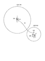
- the prohibited area may include a first prohibited area including the position of the first antenna and a second prohibited area set apart from the first prohibited area and including the position of the second antenna.
- a communication system may be provided that transmits a command signal to the mining machine so that the mining machine does not enter the prohibited area.
- the communication system may include a first communication device mounted on the vehicle and capable of transmitting information based on signals from the first antenna and the second antenna.
- the information based on the signal may include information on the position of the first antenna detected by the first detection device and information on the position of the second antenna detected by the second detection device.
- a control facility having the processing device, wherein the processing device of the control facility sets the prohibited area based on information based on the signal from the first communication device, and the communication system includes the control facility And the third communication device disposed in the mining machine, and the command signal may be transmitted from the second communication device to the third communication device.
- a mining machine management system is a mining machine management system having a central control device arranged in a control facility, which is a vehicle capable of traveling in a mine, and is arranged in the vehicle and receives radio waves from a GPS satellite. And a portable second antenna that is mounted on the vehicle so as to be releasable and that receives radio waves from a GPS satellite while being carried by an operator who has boarded the vehicle outside the vehicle.
- a first detection device that is disposed in the vehicle and detects the position of the first antenna based on a signal from the first antenna; and the first detection device that is disposed in the vehicle and that is based on a signal from the second antenna.
- a method for managing a mining machine includes: a first antenna disposed in a vehicle capable of traveling in a mine; receiving a radio wave from a GPS satellite; and a portable first mounted releasably on the vehicle. Receiving a radio wave from a GPS satellite with two antennas, detecting a position of the first antenna based on a signal from the first antenna, and the second based on a signal from the second antenna. A prohibition area for prohibiting entry of a mining machine capable of traveling in the mine so as to include the position of the first antenna and the position of the second antenna based on the detection result and detecting the position of the antenna Setting.
- a management method for a mining machine is a management method for a mining machine using a central control device arranged in a control facility, and is a first antenna arranged in a vehicle capable of traveling in a mine, from a GPS satellite.
- Receiving radio waves receiving radio waves from GPS satellites with a second antenna mounted releasably on the vehicle and carried by an operator who has boarded the vehicle outside the vehicle; Detecting the position of the first antenna based on a signal from one antenna, detecting the position of the second antenna based on a signal from the second antenna, and based on a result of the detection, Setting a forbidden area for prohibiting entry of a mining machine capable of traveling in the mine so as to include the position of the first antenna and the position of the second antenna; and traveling of the mining machine Setting the traveling condition of the mining machine so as to stop before the prohibited area in the processing device provided in the central control device, and the traveling condition set in the processing device Transmitting information to the mining machine and running the mining machine according to the information on the running
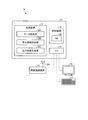
- FIG. 1 is a diagram illustrating an example of a mining machine management system according to the present embodiment.
- FIG. 2 is a diagram illustrating an example of a management apparatus according to the present embodiment.
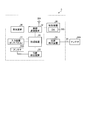
- FIG. 3 is a diagram illustrating an example of the dump truck according to the present embodiment.
- FIG. 4 is a diagram illustrating an example of a dump truck control system according to the present embodiment.
- FIG. 5 is a diagram illustrating an example of a vehicle according to the present embodiment.
- FIG. 6 is a diagram illustrating an example of a vehicle control system according to the present embodiment.
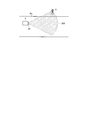
- FIG. 7 is a diagram illustrating an example of a landmark usage method according to the present embodiment.
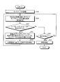
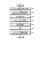
- FIG. 8 is a flowchart showing an example of a dump truck traveling method according to the present embodiment.
- FIG. 1 is a diagram illustrating an example of a mining machine management system according to the present embodiment.
- FIG. 2 is a diagram illustrating an example of a management apparatus according to the present embodiment.
- FIG. 3 is
- FIG. 9 is a schematic diagram illustrating an example of a landmark position detection process and a position registration process according to the present embodiment.
- FIG. 10 is a flowchart illustrating an example of a landmark position detection process and a position registration process according to the present embodiment.
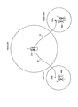
- FIG. 11 is a diagram illustrating an example of the prohibited area according to the present embodiment.
- FIG. 12 is a diagram illustrating an example of the prohibited area according to the present embodiment.
- FIG. 13 is a diagram illustrating an example of the prohibited area according to the present embodiment.
- FIG. 14 is a diagram illustrating an example of the prohibited area according to the present embodiment.
- FIG. 15 is a diagram illustrating an example of the prohibited area according to the present embodiment.
- FIG. 1 is a diagram showing an example of a mining machine management system 1 according to the present embodiment.
- FIG. 1 schematically shows a management system 1 and a site to which the management system 1 is applied.
- the management system 1 includes a management device 10 disposed in the control facility 7, and manages the mining machine.
- Mining machine management includes at least one of mining machine operation management, mining machine productivity evaluation, mining machine operator operation technique evaluation, mining machine maintenance, and mining machine abnormality diagnosis.
- Mining machinery is a general term for machinery used for various operations in mines.
- the mining machine includes at least one of a boring machine, an excavating machine, a loading machine, and a transporting machine.
- the excavating machine can excavate the mine.
- the loading machine can load a load on the transport machine.
- the loading machine includes at least one of a hydraulic excavator, an electric excavator, and a wheel loader.
- the transport machine includes a movable body that can move in the mine, and can transport a load.
- the transport machine includes a dump truck.
- the load includes at least one of sediment and ore generated by mining.
- the management system 1 manages a transport machine that can travel in the mine.
- the dump truck 2 operates in at least a part of the conveyance path HL leading to at least one of the loading site LPA, the earth discharging site DPA, and the loading site LPA and the earth discharging site DPA in the mine.
- the dump truck 2 is a movable body that can move in the mine.
- the dump truck 2 can travel at least a part of the loading site LPA, the earth discharging site DPA, and the transport path HL.
- the dump truck 2 travels on the transport path HL and can move between the loading site LPA and the earth discharging site DPA.
- the dump truck 2 is loaded with a load at the loading site LPA.
- the loading site LPA is an area (place) where loading work is performed in a mine.
- the dump truck 2 is loaded with a load at the loading position LP of the loading site LPA.
- the loading position LP is a position (loading point) where the loading operation of the load is performed in the loading field LPA.
- the loading operation is an operation for loading a load onto the dump truck 2.
- the loading machine 4 loads the load onto the dump truck 2.
- the loading machine 4 loads a load onto the dump truck 2 disposed at the loading position LP.
- the dump truck 2 unloads (discharges) the load at the dump site DPA.
- the earth removal site DPA is an area (place) where cargo discharge work is performed in a mine.
- the dump truck 2 discharges the load at the discharging position DP of the discharging site DPA.
- the discharging operation is an operation of unloading (discharging) the load from the dump truck 2.
- the load is discharged from the dump truck 2 at the dump site DPA.
- the dump truck 2 is disposed at the soil discharge position DP and discharges the load.
- the dump truck 2 is a so-called unmanned dump truck that operates in response to a command signal from the management device 10. An operator (driver) does not board the dump truck 2.
- a management system 1 transmits information to a vehicle 3 capable of traveling in a mine, a management device 10 that is disposed in a control facility 7 and manages a dump truck 2, and a landmark 8 that is installed in the mine. And a possible communication system 9.
- Vehicle 3 is a movable body that can move in the mine.
- the vehicle 3 can travel at least a part of the loading site LPA, the earth discharging site DPA, and the transport path HL.
- An operator gets on the vehicle 3. That is, the vehicle 3 is a so-called manned vehicle.
- the vehicle 3 travels in the mine in order to perform various operations related to the mine including management and maintenance of the mining machine.
- An operator gets on the vehicle 3 and moves to an arbitrary position (place) in the mine.
- the management device 10 is installed in the control facility 7 of the mine.
- the control facility 7 may be referred to as a management facility 7 or a central control room 7.
- the management device 10 may be referred to as a control device (central control device) 10 or a central control system 10.
- the management device 10 does not move.
- the management apparatus 10 may be movable.
- a plurality of landmarks 8 are installed in the mine.
- the landmarks 8 are disposed on the loading site LPA, the earth discharging site DPA, and the transport path HL, respectively.
- the landmark 8 is a stationary object.
- the landmark 8 does not move from the installed position (place).
- the management system 1 corrects the position of the dump truck 2 using the landmark 8.
- the dump truck 2 travels according to the generated travel route.
- the management system 1 corrects the position of the dump truck 2 using the landmark 8 so as to travel according to the travel path when the dump truck 2 deviates from the travel path.
- the communication system 9 transmits information among the vehicle 3, the management device 10, and the dump truck 2.
- the management device 10 and the dump truck 2 can communicate with each other via the communication system 9.
- the management device 10 and the vehicle 3 can communicate via the communication system 9.
- the dump truck 2 and the vehicle 3 can communicate with each other via the communication system 9.
- the communication system 9 includes a wireless communication system.
- the vehicle 3, the management device 10, and the dump truck 2 can communicate wirelessly via the communication system 9.
- the communication system 9 includes a repeater 6 that relays signals (radio waves) among the vehicle 3, the management device 10, and the dump truck 2.
- the position of the dump truck 2, the position of the vehicle 3, and the position of the landmark 8 are detected by using an omnidirectional positioning system (Global Positioning System: GPS).
- GPS Global Positioning System
- the GPS has a GPS satellite 5.
- the GPS detects a position in a coordinate system (GPS coordinate system) that defines latitude, longitude, and altitude.
- the position detected by GPS includes latitude, longitude, and altitude coordinate data.
- the position of the dump truck 2, the position of the vehicle 3, and the position of the landmark 8 in the mine are detected by GPS.
- the position detected by the GPS is an absolute position defined in the GPS coordinate system. In the following description, a position detected by the GPS is appropriately referred to as a GPS position.
- the GPS position is an absolute position.
- the GPS position is latitude, longitude, and altitude coordinate data (coordinate values).
- FIG. 2 is a block diagram illustrating an example of the management apparatus 10 according to the present embodiment.
- the management device 10 includes a computer system 11, a display device 16, an input device 17, and a wireless communication device 18.
- the computer system 11 includes a processing device 12, a storage device 13, and an input / output unit 15.
- the display device 16, the input device 17, and the wireless communication device 18 are connected to the computer system 11 via the input / output unit 15.
- the input / output unit 15 is used for input / output (interface) of information between the processing device 12 and at least one of the display device 16, the input device 17, and the wireless communication device 18.
- the processing device 12 includes a CPU (Central Processing Unit).
- the processing device 12 executes various processes related to the management of the dump truck 2.
- the processing device 12 includes a data processing unit 12A, a prohibited area setting unit 12B, and a travel route generation unit 12C.
- the data processing unit 12 ⁇ / b> A processes information regarding the position of the dump truck 2, information regarding the position of the vehicle 3, and information regarding the position of the landmark 8 acquired via the communication system 9.
- the prohibited area setting unit 12B sets a prohibited area where entry of the dump truck 2 is prohibited in the mine.
- the travel route generation unit 12C generates a travel route on which the dump truck 2 travels.
- the dump truck 2 travels in accordance with the travel route generated by the travel route generation unit 12C in at least a part of the loading site LPA, the earth removal site DPA, and the transport route HL.
- the storage device 13 is connected to the processing device 12.
- the storage device 13 includes at least one of a RAM (Random Access Memory), a ROM (Read Only Memory), a flash memory, and a hard disk drive.
- the storage device 13 stores various types of information related to the management of the dump truck 2.
- the storage device 13 includes a database 13B in which information is registered.
- the storage device 13 stores a computer program for causing the processing device 12 to execute various processes.
- the processing device 12 uses the computer program stored in the storage device 13 to process information about the position, set a prohibited area, and generate a travel route.
- the display device 16 includes, for example, a flat panel display such as a liquid crystal display.
- the display device 16 can display information about the position of the dump truck 2, information about the position of the vehicle 3, and information about the position of the landmark 8.
- the input device 17 includes at least one of a keyboard, a touch panel, and a mouse.
- the input device 17 functions as an operation unit that can input an operation signal to the processing device 12.
- An administrator of the control facility 7 can input an operation signal to the processing device 12 by operating the input device 17.
- the communication system 9 includes a wireless communication device 18.
- the wireless communication device 18 is disposed in the control facility 7.
- the wireless communication device 18 is connected to the processing device 12 via the input / output unit 15.
- the wireless communication device 18 has an antenna 18A.
- the wireless communication device 18 can receive information transmitted from at least one of the dump truck 2 and the vehicle 3.
- Information received by the wireless communication device 18 is output to the processing device 12.
- Information received by the wireless communication device 18 is stored (registered) in the storage device 13.
- the wireless communication device 18 can transmit information to at least one of the dump truck 2 and the vehicle 3.
- FIG. 3 is a diagram schematically showing the appearance of the dump truck 2 according to the present embodiment.
- FIG. 4 is a control block diagram of the dump truck 2 according to the present embodiment.
- the dump truck 2 includes a vehicle body 21, a vessel 22, wheels 23, a non-contact sensor 24 that detects the landmark 8 in a non-contact manner, a processing device 20, and a storage device. 25, a gyro sensor 26, a speed sensor 27, a wireless communication device 28 to which an antenna 28A is connected, and a position detection device 29 to which an antenna 29A is connected.
- a driving device is disposed on the vehicle body 21.
- the drive device includes an internal combustion engine such as a diesel engine, a generator that is operated by the internal combustion engine, and an electric motor that is operated by electric power generated by the generator.
- the wheel 23 is driven by the electric motor.
- the wheel 23 includes a tire and a wheel.
- the wheel 23 is rotated by the power transmitted from the drive device of the vehicle main body 21.
- the power of the internal combustion engine may be transmitted to the wheel 23 via a transmission including a torque converter.
- the vessel 22 includes a loading platform on which a load is loaded.
- the vessel 22 is disposed on the upper portion of the vehicle body 21 so as to be swingable.
- the load is loaded into the vessel 22 by the loading machine 4.
- the vessel 22 is lifted and the load is discharged.
- the non-contact sensor 24 is disposed at the front part of the vehicle main body 21.
- the non-contact sensor 24 detects the landmark 8 installed in the mine without contact.
- the non-contact sensor 24 includes a radar.
- the non-contact sensor 24 emits radio waves and irradiates the landmarks 8 with the radio waves. At least a part of the radio wave irradiated to the landmark 8 is reflected by the landmark 8.
- the non-contact sensor 24 receives the radio wave reflected by the landmark 8. Thereby, the non-contact sensor 24 can detect the direction and distance of the landmark 8 with respect to the non-contact sensor 24.
- the non-contact sensor 24 detects the relative position between the non-contact sensor 24 and the landmark 8.
- the non-contact sensor 24 is fixed to the vehicle main body 21.
- the non-contact sensor 24 is connected to the processing device 20.
- the non-contact sensor 24 outputs a detection signal to the processing device 20.
- the processing device 20 can obtain the relative position between the dump truck 2 and the landmark 8 based on the detection signal of the non-contact sensor 24. That is, the relative position between the dump truck 2 and the landmark 8 is detected by the non-contact sensor 24 detecting the relative position with respect to the landmark 8.
- the non-contact sensor 24 functions as an obstacle detection sensor that detects an obstacle in front of the vehicle main body 21.
- the gyro sensor 26 detects the direction (direction change amount) of the dump truck 2.
- the gyro sensor 26 is connected to the processing device 20.
- the gyro sensor 26 outputs a detection signal to the processing device 20.
- the processing device 20 can determine the direction (direction change amount) of the dump truck 2 based on the detection signal of the gyro sensor 26.
- the speed sensor 27 detects the traveling speed of the dump truck 2.
- the speed sensor 27 detects the rotational speed of the wheels 23 and detects the speed (traveling speed) of the dump truck 2.
- the speed sensor 27 is connected to the processing device 20.
- the speed sensor 27 outputs a detection signal to the processing device 20.
- the processing device 20 can determine the moving distance of the dump truck 2 based on the detection signal of the speed sensor 27 and the time information from the timer built in the processing device 20.
- the processing device 20 is mounted on the dump truck 2.
- the processing device 20 includes a CPU (Central Processing Unit).
- the processing device 20 executes various processes related to the management of the dump truck 2.
- the processing device 20 includes a data processing unit, a prohibited area setting unit, and a travel route generation unit, and can perform processing equivalent to the processing device 12 arranged in the control facility 7. That is, the data processing unit of the processing device 20 can process information regarding the position of the dump truck 2, information regarding the position of the vehicle 3, and information regarding the position of the landmark 8.
- the prohibited area setting unit of the processing device 20 can set a prohibited area where entry of the dump truck 2 is prohibited in the mine.
- the travel route generation unit of the processing device 20 can generate a travel route along which the dump truck 2 travels.
- the processing device 20 includes a travel control unit 20D.
- the traveling control unit 20D controls traveling of the dump truck 2 so that the dump truck 2 travels according to the generated traveling route.
- Control of traveling of the dump truck 2 includes control of operation of the dump truck 2.
- the operation of the dump truck 2 includes at least one operation of a steering, an accelerator, and a brake.
- the data processing unit, the prohibited area setting unit, and the travel route generation unit may be omitted.
- the storage device 25 is mounted on the dump truck 2.
- the storage device 25 is connected to the processing device 20.
- the storage device 25 includes at least one of a RAM (Random Access Memory), a ROM (Read Only Memory), a flash memory, and a hard disk drive.
- the storage device 25 stores various types of information related to the management of the dump truck 2.
- the storage device 25 includes a database 25B in which information is registered.
- the storage device 25 stores a computer program for causing the processing device 20 to execute various processes.
- the storage device 25 is capable of storing (registerable) information equivalent to the storage device 13 arranged in the control facility 7.
- the communication system 9 includes a wireless communication device 28.
- the wireless communication device 28 is disposed on the dump truck 2.
- the wireless communication device 28 is connected to the processing device 20.
- the wireless communication device 28 has an antenna 28A.
- the wireless communication device 28 can receive information (including a command signal) transmitted from at least one of the management device 10 and the vehicle 3.
- Information received by the wireless communication device 28 is output to the processing device 20.
- Information received by the wireless communication device 28 is stored (registered) in the storage device 25.
- the processing device 20 (travel control unit 20D) can control the travel of the dump truck 2 according to the command signal received by the wireless communication device 28.
- the command signal includes information related to the travel route and information related to the travel speed of the dump truck 2.
- the wireless communication device 28 can transmit information to at least one of the management device 10 and the vehicle 3.
- the position detection device 29 is disposed on the dump truck 2.
- the position detection device 29 is connected to the processing device 20.
- the position detection device 29 includes a GPS receiver and detects the position (GPS position) of the dump truck 2.
- the position detection device 29 has a GPS antenna 29A.
- the position detection device 29 detects the position (GPS position) of the antenna 29A.
- the antenna 29A is disposed in the dump truck 2. By detecting the position (GPS position) of the antenna 29A, the position (GPS position) of the dump truck 2 is detected.
- the antenna 29A receives radio waves from the GPS satellite 5.
- the antenna 29A outputs a signal based on the received radio wave to the position detection device 29.
- the position detection device 29 detects the position (GPS position) of the antenna 29A based on the signal from the antenna 29A.
- the position detection device 29 converts the signal based on the radio wave from the GPS satellite 5 received by the antenna 29A into an electric signal, and calculates the position (GPS position) of the antenna 29A.
- the GPS position of the dump truck 2 is obtained by calculating the GPS position of the antenna 29A.
- FIG. 5 is a diagram schematically illustrating the appearance of the vehicle 3 according to the present embodiment.
- FIG. 6 is a control block diagram of the vehicle 3 according to the present embodiment.
- the vehicle 3 is connected to a vehicle body 37, wheels 38, a processing device 30, a storage device 39, a wireless communication device 32 to which an antenna 32 ⁇ / b> A is connected, and an antenna 33 ⁇ / b> A.
- the position detecting device 33, the display device 36, and the input device 31 are provided.
- the vehicle body 37 is provided with an engine.
- the wheel 38 is rotated by power transmitted from the engine of the vehicle main body 37.
- the wheel 38 includes a tire and a wheel.
- the vehicle 3 travels.
- the worker WM gets on the vehicle 3.
- the vehicle 3 travels by the driving operation of the worker WM.
- the processing device 30 includes a CPU (Central Processing Unit).
- the processing device 30 executes various processes related to the management of the dump truck 2.
- the processing device 30 includes a data processing unit, a prohibited area setting unit, and a travel route generation unit, and is equivalent to the processing device 12 disposed in the control facility 7 and the processing device 20 disposed in the dump truck 2. Can be executed. That is, the data processing unit of the processing device 30 can process the information related to the position of the dump truck 2, the information related to the position of the vehicle 3, and the information related to the position of the landmark 8 acquired via the communication system 9.
- the prohibited area setting unit of the processing device 30 can set a prohibited area where entry of the dump truck 2 is prohibited in the mine.
- the travel route generation unit of the processing device 30 can generate a travel route on which the dump truck 2 travels. In the processing device 30, the data processing unit, the prohibited area setting unit, and the travel route generation unit may be omitted.
- the storage device 39 is mounted on the vehicle 3.
- the storage device 39 is connected to the processing device 30.
- the storage device 39 includes at least one of a RAM (Random Access Memory), a ROM (Read Only Memory), a flash memory, and a hard disk drive.
- the storage device 39 stores various types of information related to the management of the dump truck 2.
- the storage device 39 includes a database 39B in which information is registered.
- the storage device 39 stores a computer program for causing the processing device 30 to execute various processes.
- the storage device 39 can store (register) information equivalent to the storage device 13 arranged in the control facility 7 and the storage device 25 arranged in the dump truck 2.
- the display device 36 includes, for example, a flat panel display such as a liquid crystal display.
- the display device 36 can display information about the position of the dump truck 2, information about the position of the vehicle 3, and information about the position of the landmark 8.
- the input device 31 includes at least one of a keyboard, a touch panel, and a mouse.
- the input device 31 functions as an operation unit that can input an operation signal to the processing device 30.
- An operator (driver) WM of the vehicle 3 can input an operation signal to the processing device 30 by operating the input device 31.
- the communication system 9 includes a wireless communication device 32.
- the wireless communication device 32 is disposed in the vehicle 3.
- the wireless communication device 32 is connected to the processing device 30.
- the wireless communication device 32 has an antenna 32A.
- the wireless communication device 32 can receive information (including a command signal) transmitted from at least one of the management device 10 and the dump truck 2.
- Information received by the wireless communication device 32 is output to the processing device 30.
- Information received by the wireless communication device 32 is stored (registered) in the storage device 39.
- the wireless communication device 32 can transmit information to at least one of the management device 10 and the dump truck 2.
- the position detection device 33 is disposed in the vehicle 3.
- the position detection device 33 is connected to the processing device 30.
- the position detection device 33 includes a GPS receiver and detects the position of the vehicle 3 (GPS position).
- the position detection device 33 includes a GPS antenna 33A.
- the position detection device 33 detects the position (GPS position) of the antenna 33A.
- the antenna 33 ⁇ / b> A is disposed on the vehicle 3.
- the position (GPS position) of the vehicle 3 is detected by detecting the position (GPS position) of the antenna 33A.
- the antenna 33 ⁇ / b> A receives radio waves from the GPS satellite 5.
- the antenna 33 ⁇ / b> A outputs a signal based on the received radio wave to the position detection device 33.
- the position detection device 33 detects the position (GPS position) of the antenna 33A based on the signal from the antenna 33A.
- the position detection device 33 converts the signal based on the radio wave from the GPS satellite 5 received by the antenna 33A into an electric signal, and calculates the position (GPS position) of the antenna 33A.
- the GPS position of the vehicle 3 is obtained by calculating the GPS position of the antenna 33A.
- a GPS antenna 34A is mounted on the vehicle 3.
- the antenna 34 ⁇ / b> A receives radio waves from the GPS satellite 5.
- the antenna 34A is releasably mounted on the vehicle 3.
- the antenna 34 ⁇ / b> A released from the vehicle 3 is movable outside the vehicle 3.
- the antenna 34 ⁇ / b> A can move to a position away from the vehicle 3.
- the antenna 34A is portable.
- the worker WM can carry (hold) the antenna 34A.
- the worker WM can move to the outside of the vehicle 3 while holding the antenna 34A.
- the worker WM can move to a position away from the vehicle 3 while holding the antenna 34A.
- the antenna 34 ⁇ / b> A is capable of receiving radio waves from the GPS satellite 5 while being disposed outside the vehicle 3.
- the vehicle 3 is provided with a position detection device 34.
- the position detection device 34 is connected to the processing device 30.
- the position detection device 34 includes a GPS receiver.
- the position detection device 34 and the antenna 34 ⁇ / b> A are connected via a cable 35.
- the position detection device 34 detects the position (GPS position) of the antenna 34A.
- the antenna 34A is carried by the worker WM
- the position (GPS position) of the worker WM is detected by detecting the position (GPS position) of the antenna 34A.
- the antenna 34A is disposed in the vicinity of the object, the position (GPS position) of the object is detected by detecting the position (GPS position) of the antenna 34A.
- the antenna 34 ⁇ / b> A receives radio waves from the GPS satellite 5.
- the antenna 34 ⁇ / b> A outputs a signal based on the received radio wave to the position detection device 34 via the cable 35.
- the position detection device 34 detects the position (GPS position) of the antenna 34A based on the signal from the antenna 34A.
- the position detection device 34 converts a signal based on the radio wave from the GPS satellite 5 received by the antenna 34A into an electric signal, and calculates the position (GPS position) of the antenna 34A. By calculating the GPS position of the antenna 34A, the GPS position of an object (including the worker WM) disposed in the vicinity of the antenna 34A is obtained.
- FIG. 7 is a diagram schematically illustrating an example of a state in which the landmark 8 is detected by the non-contact sensor 24 of the dump truck 2.
- the landmarks 8 are disposed on the loading site LPA, the earth discharging site DPA, and the transport path HL, respectively.
- the landmark 8 is disposed on the outer side (road shoulder) of the transport path HL.
- a plurality of landmarks 8 are arranged at intervals along the transport path HL.
- the landmark 8 may be arranged, for example, every 100 m.
- Landmark 8 is a stationary object.
- the landmark 8 does not move from the installed position (place).
- the landmark 8 is a structure (characteristic) arranged along the travel route.
- the landmark 8 is detected by a non-contact sensor 24 disposed on the dump truck 2.
- the landmark 8 has a reflection part (reflection surface) that can reflect the radio wave emitted from the non-contact sensor 24.
- the reflectance (reflection intensity) of the reflection part of the landmark 8 with respect to the radio wave is higher than the reflectance (reflection intensity) of an object around the landmark 8.
- the objects around the landmark 8 include at least one of a mine rock, a traveling dump truck 2, and a vehicle 3.
- the non-contact sensor 24 includes a radar.
- the non-contact sensor 24 has a launcher that can emit radio waves and a receiver that can receive radio waves.
- the non-contact sensor 24 is disposed at the front portion of the dump truck 2. At least a part of the radio wave emitted from the emitting part of the non-contact sensor 24 and applied to the landmark 8 is reflected by the reflecting part of the landmark 8.
- the non-contact sensor 24 receives the radio wave from the landmark 8 reflected by the reflecting unit at the receiving unit.
- the non-contact sensor 24 receives radio waves from the landmark 8 and detects the relative position between the non-contact sensor 24 and the landmark 8.
- the non-contact sensor 24 is fixed to the dump truck 2. By detecting the relative position between the non-contact sensor 24 and the landmark 8, the relative position between the dump truck 2 and the landmark 8 is detected.
- the relative position of the landmark 8 with respect to the dump truck 2 is detected by a non-contact sensor 24 disposed on the dump truck 2.
- the radio wave from the non-contact sensor 24 propagates so as to spread from the launching part of the non-contact sensor 24. Since the landmark 8 is arranged in the propagation region (propagation space) where the radio wave emitted from the non-contact sensor 24 propagates, the non-contact sensor 24 can detect the landmark 8. Further, the radio wave emitted from the non-contact sensor 24 is attenuated as it travels. That is, the intensity of the radio wave emitted from the non-contact sensor 24 decreases with the progress of the radio wave.
- the non-contact sensor 24 Since the landmark 8 is disposed in a propagation region (propagation space) in which the radio wave emitted from the non-contact sensor 24 is propagated in a state where the intensity is maintained at a predetermined value or more, the non-contact sensor 24 is configured to display the landmark 8. It can be detected.
- a radio wave propagation area (propagation space) in which the non-contact sensor 24 can detect the landmark 8 based on a radio wave emitted from the non-contact sensor 24 is appropriately set as a detection area (detection space) of the non-contact sensor 24. ) 300.
- the non-contact sensor 24 can detect the landmark 8.
- the non-contact sensor 24 may detect the landmark 8 using detection light (laser light). That is, the non-contact sensor 24 may include an emission part that can emit detection light and a light receiving part that can receive at least part of the detection light emitted from the emission part and reflected by the landmark 8. Since the landmark 8 is arranged in the irradiation region (irradiation space) irradiated with the detection light emitted from the non-contact sensor 24, the non-contact sensor 24 can detect the landmark 8. Further, the detection light emitted from the non-contact sensor 24 attenuates as it progresses.
- detection light laser light
- the non-contact sensor 24 8 can be detected.
- the detection region 300 of the non-contact sensor 24 is a detection light that can detect the landmark 8 based on the detection light emitted from the non-contact sensor 24.
- the position (GPS position, absolute position) of the landmark 8 is detected using GPS (omnidirectional positioning system).
- the GPS position of the landmark 8 detected using GPS is registered in the storage device 13 of the management device 10.
- Information regarding the relative position between the dump truck 2 and the landmark 8 detected using the non-contact sensor 24 is transmitted to the management device 10 (processing device 12) via the communication system 9.
- the processing device 12 includes information on the relative position between the dump truck 2 and the landmark 8 detected using the non-contact sensor 24 and the absolute position (GPS position) of the landmark 8 registered (stored) in the storage device 13. ), The absolute position (GPS position) of the dump truck 2 can be obtained.
- GPS position of the landmark 8 detected using GPS may be registered in the storage device 25 of the dump truck 2.
- the processing device 20 of the dump truck 2 uses the non-contact sensor 24 to detect the relative position between the dump truck 2 and the landmark 8, and the landmark 8 registered (stored) in the storage device 25.
- the absolute position (GPS position) of the dump truck 2 may be obtained based on the information regarding the absolute position (GPS position).
- the processing device 12 transmits a command signal to the processing device 20 (travel control unit 20D) of the dump truck 2 via the communication system 9 (wireless communication device 18 and wireless communication device 28).
- the command signal includes information related to the traveling condition of the dump truck 2.
- the information related to the travel condition includes information related to the travel route generated by the processing device 12 and information related to the travel speed of the dump truck 2.
- the processing device 20 operates the dump truck 2 (at least one operation of steering, accelerator, and brake) based on the command signal from the processing device 12 transmitted via the communication system 9. To control the traveling of the dump truck 2.
- the dump truck 2 travels based on dead reckoning navigation.
- the dump truck 2 has a loading field LPA according to a traveling condition including a traveling route generated by the processing device 12 of the management device 10 and a traveling speed (target traveling speed) set by the processing device 12. It travels at least part of the earth removal site DPA and the conveyance path HL.
- the processing device 20 causes the dump truck 2 to travel in at least a part of the mine according to the generated travel route while estimating the current position of the dump truck 2 using dead reckoning navigation.
- Dead reckoning refers to navigation in which the current position of the object (dump truck 2) is estimated based on the azimuth (azimuth change amount) and the moving distance from the starting point with known longitude and latitude.
- the azimuth (azimuth change amount) of the dump truck 2 is detected by using a gyro sensor 26 disposed on the dump truck 2.
- the moving distance of the dump truck 2 is detected using a speed sensor 27 arranged on the dump truck 2.
- the detection signal of the gyro sensor 26 and the detection signal of the speed sensor 27 are output to the processing device 20 of the dump truck 2. Based on the detection signal from the gyro sensor 26, the processing device 20 can determine the direction (direction change amount) of the dump truck 2 from a known starting point.
- the processing device 20 can determine the moving distance of the dump truck 2 from a known starting point based on the detection signal from the speed sensor 27. Based on the detection signal from the gyro sensor 26 and the detection signal from the speed sensor 27, the processing device 20 calculates a control amount related to the traveling of the dump truck 2 so that the dump truck 2 travels according to the travel route generated. .
- the control amount includes a steering amount (steering command) and a travel speed adjustment amount (speed command).
- the processing device 20 controls the travel (operation) of the dump truck 2 based on the calculated control amount so that the dump truck 2 travels according to the travel route.
- the processing device 20 uses the position (estimated position) of the dump truck 2 derived (estimated) by dead reckoning navigation as the information on the position (GPS position) of the dump truck 2 detected by the position detection device 29.
- the dump truck 2 is caused to travel while being corrected using it.
- the processing device 20 Based on the detection signal from the gyro sensor 26, the detection signal from the speed sensor 27, and the information related to the GPS position of the dump truck 2 from the position detection device 29, the processing device 20 causes the dump truck 2 to travel along the travel route. As described above, the control amount relating to the traveling of the dump truck 2 including the correction amount for correcting the position of the dump truck 2 is calculated. The processing device 20 controls the travel (operation) of the dump truck 2 based on the calculated correction amount and control amount so that the dump truck 2 travels according to the travel route.
- the dump truck 2 travels while the estimated position obtained by dead reckoning is corrected using the landmark 8
- the detection accuracy by GPS is high.
- the processing device 20 corrects the estimated position obtained by dead reckoning using the landmark 8 when it is difficult to correct using the GPS.
- the processing device 20 detects the position (estimated position) of the dump truck 2 obtained by dead reckoning using the landmark 8 and the non-contact sensor 24. Correction is performed using information on the position (GPS position, absolute position) of the dump truck 2.
- FIG. 8 is a flowchart showing an example of a traveling method of the dump truck 2 including correction of the estimated position using the landmark 8 and the non-contact sensor 24.
- a plurality of landmarks 8 Prior to the operation of the dump truck 2, a plurality of landmarks 8 are installed in the loading site LPA, the earth discharging site DPA, and the conveyance path HL. Each of the positions (GPS position, absolute position) of the plurality of landmarks 8 is detected using GPS. Information regarding the position (GPS position) of the landmark 8 detected using GPS is registered (stored) in the storage device 13 (step SA1). Information regarding the position of the landmark 8 may be transmitted to the dump truck 2 via the communication system 9 and registered (stored) in the storage device 25. The installation of the landmark 8 and the detection of the position of the landmark 8 using GPS may be performed in parallel with the operation of the dump truck 2.
- the processing device 20 causes the dump truck 2 to travel based on dead reckoning navigation (step SA2). In other words, the processing device 20 determines the dump truck 2 based on the direction (direction change amount) of the dump truck 2 obtained from the detection signal of the gyro sensor 26 and the moving distance of the dump truck 2 obtained from the detection signal of the speed sensor 27. The dump truck 2 is caused to travel while estimating the position of 2.
- the detection signal of the non-contact sensor 24 is output to the processing device 20.
- the processing device 20 determines whether or not the landmark 8 has been detected based on the detection signal from the non-contact sensor 24 (step SA3).
- step SA3 If it is determined in step SA3 that the landmark 8 has been detected, the processing device 20 uses the absolute position (GPS position) of the landmark 8 registered in step SA1 and the dump detected using the non-contact sensor 24. The relative positions of the track 2 and the landmark 8 are compared (step SA4). Based on information on the relative position between the dump truck 2 and the landmark 8 detected using the non-contact sensor 24 and information on the absolute position of the registered landmark 8, the absolute position of the dump truck 2 is determined. A position (GPS position) is derived.
- the processing device Reference numeral 20 denotes information on the position (absolute position) of the landmark 8 corresponding to the landmark 8 detected by the non-contact sensor 24 among the plurality of landmarks 8 registered in the storage device 13 (storage device 25). Extract. Among the plurality of registered landmarks 8, the landmark 8 corresponding to the landmark 8 detected by the non-contact sensor 24 uses the non-contact sensor 24 among the plurality of registered landmarks 8.
- the landmark 8 corresponding to the landmark 8 detected by the non-contact sensor 24 is derived based on dead reckoning navigation among the plurality of registered landmarks 8.
- the landmark 8 is determined to be disposed in the detection region 300 of the non-contact sensor 24 of the dump truck 2 existing at the position (estimated position).
- the processing device 20 for example, the position (estimated position) of the dump truck 2 derived based on dead reckoning navigation when the landmark 8 is detected from the plurality of registered landmarks 8 using the non-contact sensor 24.
- the landmark 8 present at the position closest to (GPS position) is extracted.
- the landmarks 8 are arranged at intervals of 100 m, for example.
- the size of the detection area 300 of the non-contact sensor 24 in the traveling direction of the dump truck 2 is, for example, 50 m. Therefore, the processing device 20 can extract information on the position (absolute position) of the landmark 8 corresponding to the landmark 8 detected by the non-contact sensor 24 from the plurality of registered landmarks 8.
- the processing apparatus 20 corrects the position (estimated position) of the dump truck 2 based on the result of comparison in Step SA4 (Step SA5). For example, when it is determined that the position of the dump truck 2 is deviated from the travel route generated by the processing device 12, the processing device 20 determines the position of the dump truck 2 so that the dump truck 2 travels according to the travel route. Correct.
- the processing device 20 includes a detection signal from the gyro sensor 26, a detection signal from the speed sensor 27, information on the relative position between the dump truck 2 and the landmark 8 detected using the non-contact sensor 24, Based on the information on the absolute position (GPS position) of the landmark 8 stored in the storage device 13 (storage device 25), the position of the dump truck 2 is corrected so that the dump truck 2 travels according to the travel route.
- a control amount relating to the traveling of the dump truck 2 including the correction amount is calculated.
- the processing device 20 controls the travel (operation) of the dump truck 2 based on the calculated correction amount and control amount so that the dump truck 2 travels according to the travel route.
- step SA6 it is determined whether or not the vehicle can travel by dead reckoning alone without using the detection result of the landmark 8 (step SA6). If the traveling distance from the position where the estimated position of the dump truck 2 is corrected (one or both of correction using GPS and correction using the landmark 8) is within a predetermined distance, the processing device 20 performs dead reckoning navigation. It is determined that the error in the estimated position due to only does not cause a problem, and the traveling of the dump truck 2 based on dead reckoning navigation is continued (step SA2).
- the predetermined distance is a distance that can be traveled without significantly deviating from the travel route from the position where the estimated position is corrected, and is a predetermined distance.
- step SA7 it is determined in step SA6 that traveling is not possible only by dead reckoning, the dump truck 2 is stopped (stopped) until position detection by GPS is recovered (step SA7).
- the processing device 20 of the dump truck 2 manages the traveling of the dump truck 2
- the management device 10 travels the dump truck 2 so that the dump truck 2 travels on the generated travel route by dead reckoning navigation. (Operation) may be controlled.
- the processing device 12 may correct the position (estimated position) of the dump truck 2 obtained by dead reckoning based on the detection result of the position detecting device 29.
- the processing device 12 may correct the position (estimated position) of the dump truck 2 obtained by dead reckoning based on the detection result of the non-contact sensor 24.
- the landmark 8 position detection process is a process for detecting the GPS position of the landmark 8.
- the position registration process of the landmark 8 is a process of registering (storing) the GPS position (information on the GPS position) of the detected landmark 8 in the storage device 13 (database 13B).
- the GPS position of the landmark 8 may be registered in the storage device 25 (database 25B) of the dump truck 2.
- FIG. 9 is a diagram illustrating an example of a position detection process and a position registration process for the landmark 8 according to the present embodiment.
- the position (GPS position) of the landmark 8 installed in the mine is detected using GPS.
- the position of the landmark 8 is detected using a GPS antenna 34A.
- the vehicle 3 on which the worker WM has boarded moves to a position near the position detection target and the position registration target landmark 8.
- the antenna 34 ⁇ / b> A mounted on the vehicle 3 the vehicle 3 moves to the position detection target and the position registration target landmark 8.
- the vehicle 3 moves (runs) by the driving operation of the worker WM.
- the antenna 34A carried (held) by the worker WM is moved to the outside of the vehicle 3.
- the worker WM moves to the outside of the vehicle 3 with the antenna 34A being carried (held).
- the antenna 34 ⁇ / b> A is carried (held) by the worker WM and taken out of the vehicle 3.
- the position detection device 34 is disposed inside the vehicle 3.
- the antenna 34 ⁇ / b> A and the position detection device 34 are connected via a cable 35.
- an antenna 34A is installed in the vicinity of the landmark 8 installed in the mine.
- the antenna 34A is installed in the vicinity of the landmark 8 by the worker WM.
- the antenna 34A is held by the worker WM.
- the antenna 34 ⁇ / b> A receives radio waves from the GPS satellite 5 while being disposed outside the vehicle 3.
- a signal based on the radio wave from the GPS satellite 5 received by the antenna 34 ⁇ / b> A is output to the position detection device 34 via the cable 35.
- the position detection device 34 detects the position (GPS position) of the antenna 34A based on the signal from the antenna 34A. As shown in FIG.
- the antenna 34 ⁇ / b> A outputs a signal based on the radio wave from the GPS satellite 5 to the position detection device 34 while being installed in the vicinity of the landmark 8. Therefore, the GPS position of the landmark 8 is obtained by obtaining the GPS position of the antenna 34 ⁇ / b> A by the position detection device 34. As shown in FIG. 9, not only the landmark 8 but also the worker WM exists in the vicinity of the antenna 34A. Therefore, when the GPS position of the antenna 34A is obtained by the position detection device 34, the GPS position of the worker WM is also obtained. That is, in the present embodiment, the position detection device 34 simultaneously detects the GPS position of the antenna 34A, the GPS position of the landmark 8, and the GPS position of the worker WM.
- Information based on the signal from the antenna 34 ⁇ / b> A is transmitted to the wireless communication device 18 of the management device 10 by the wireless communication device 32 mounted on the vehicle 3.
- the information based on the signal from the antenna 34A includes information on the position (GPS position) of the antenna 34A detected by the position detection device 34 based on the signal from the antenna 34A, and the position of the landmark 8 (GPS Information on the position) and information on the position (GPS position) of the worker WM.
- the processing device 30 of the vehicle 3 transmits information related to the position of the antenna 34 ⁇ / b> A, information related to the position of the landmark 8, and information related to the position of the worker WM from the wireless communication device 32.
- the wireless communication device 18 of the management device 10 receives information from the wireless communication device 32 of the vehicle 3.
- the processing device 12 of the management device 10 processes information regarding the position transmitted from the vehicle 3 via the communication system 9 including the wireless communication device 32 and the wireless communication device 18.
- the processing device 12 registers information related to the position (GPS position) of the landmark 8 obtained using the antenna 34A in the storage device 13 (database 13B).
- the worker WM performs work outside the vehicle 3.
- the work of the worker WM may not be performed smoothly.
- the worker WM may have to interrupt the work.
- productivity and workability in the mine may be reduced.
- the work may be hindered from the viewpoint of ensuring the safety of the worker WM.
- the productivity in the mine may be lowered.
- a prohibited area 100 that prohibits the entry of the dump truck 2 is set so as to include the position of the antenna 34A. Thereby, the fall of the productivity in a mine is suppressed.
- FIG. 10 is a flowchart showing an example of the position detection process and the position registration process for the landmark 8 according to the present embodiment.
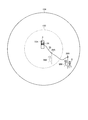
- FIG. 11 is a schematic diagram illustrating an example of the prohibited area 100 according to the present embodiment.
- the vehicle 3 on which the worker WM is boarding moves to the vicinity of the landmark 8 for the position detection process and the position registration process of the landmark 8.
- the antenna 34A and the position detection device 34 are connected via the cable 35 (step SB1).
- the antenna 33A disposed in the vehicle 3 continues to receive radio waves from the GPS satellite 5.
- the position detection device 33 detects the position (GPS position) of the antenna 33A based on the signal from the antenna 33A.
- the antenna 34A mounted on the vehicle 3 continues to receive radio waves from the GPS satellite 5 before the landmark 8 position detection process and before the position registration process.
- the position detection device 34 detects the position (GPS position) of the antenna 34A based on the signal from the antenna 34A.
- Information regarding the position (GPS position) of the antenna 33 ⁇ / b> A detected by the position detection device 33 and information regarding the position (GPS position) of the antenna 34 ⁇ / b> A detected by the position detection device 34 are output to the processing device 30.
- the processing device 30 transmits information on the position (GPS position) of the antenna 33A detected by the position detection device 33 and information on the position (GPS position) of the antenna 34A detected by the position detection device 34 from the wireless communication device 32.
- the wireless communication device 32 mounted on the vehicle 3 relates to information on the position (GPS position) of the antenna 33A detected by the position detection device 33 and information on the position (GPS position) of the antenna 34A detected by the position detection device 34.
- the information is transmitted to the wireless communication device 18 of the management device 10.
- the wireless communication device 18 of the management device 10 receives the information regarding the GPS position of the antenna 33A and the information regarding the GPS position of the antenna 34A from the wireless communication device 32, and outputs them to the processing device 12. Thereby, the processing apparatus 12 acquires the information regarding the GPS position of the antenna 33A and the information regarding the GPS position of the antenna 34A.
- the input device 31 arranged on the vehicle 3 is operated.
- the worker WM operates the input device 31 before performing the position detection process of the landmark 8 outside the vehicle 3.
- the input device 31 functions as an operation unit that can input an operation signal to the processing device 30.
- the worker WM operates the input device 31 to start the position detection process for the landmark 8 (step SB2).
- the input device 31 includes a touch panel.
- the touch panel includes a start button for instructing the processing device 30 to start the landmark 8 position detection process.
- the operation unit includes a start button. The worker WM presses (operates) the start button.
- the operation signal is input to the processing device 30 by operating the operation unit (start button) of the input device 31.
- the processing device 30 transmits an operation signal input from the operation unit of the input device 31 from the wireless communication device 32.
- the wireless communication device 18 of the management device 10 receives the operation signal from the wireless communication device 32 and outputs it to the processing device 12.
- the processing device 12 sets the prohibited area 100 that prohibits the entry of the dump truck 2 so as to include the position of the antenna 34A (step SB3).
- the processing device 12 may simultaneously acquire an operation signal from the input device 31 and set the prohibited area 100.
- the processing device 12 may set the prohibited area 100 after a predetermined time has elapsed (for example, after 1 second) from the acquisition of the operation signal from the input device 31.
- the processing device 12 sets the prohibited region 100 so as to include the position of the antenna 34A based on the detection result of the position detection device 34 acquired via the communication system 9.
- the position detection device 34 detects the GPS position of the antenna 34A.
- the processing device 12 can set the prohibited region 100 so as to include the GPS position of the antenna 34A based on the GPS coordinate system.
- the prohibited area 100 is set before the worker WM goes outside the vehicle 3 (in a state where the worker WM is inside the vehicle 3). In the present embodiment, the prohibited area 100 is set in a state where the antenna 34A is mounted on the vehicle 3 (in a state where the antenna 34A is disposed inside the vehicle 3).
- the prohibition area 100 that prohibits the entry of the dump truck 2 is set so as to include the position of the antenna 33A before the position detection processing of the landmark 8 and before the position registration processing.
- the processing device 12 sets the prohibited region 100 so as to include the position of the antenna 33 ⁇ / b> A based on the detection result of the position detection device 33 acquired via the communication system 9.
- the position detection device 33 detects the GPS position of the antenna 33A.
- the processing device 12 can set the prohibited area 100 so as to include the GPS position of the antenna 33A based on the GPS coordinate system.
- the processing device 12 sets the prohibited area 100 so that the antenna 33 ⁇ / b> A and the vehicle 3 are disposed inside the prohibited area 100.
- the processing device 12 transmits a command signal to the dump truck 2 via the communication system 9 so that the dump truck 2 does not enter the prohibited area 100.
- the command signal is transmitted from the wireless communication device 18 disposed in the control facility 7 to the wireless communication device 28 disposed in the dump truck 2.
- the command signal includes information related to a traveling condition set so that the traveling dump truck 2 stops before the prohibited area 100 (so as not to enter the prohibited area 100).
- the wireless communication device 28 of the dump truck 2 receives the command signal from the wireless communication device 18 of the management device 10 and outputs it to the processing device 20.
- the processing device 20 (travel control unit 20D) controls the travel (operation) of the dump truck 2 so that the dump truck 2 does not enter the prohibited area 100.
- the prohibited area 100 is defined in the GPS coordinate system.
- the processing device 12 (travel route generation unit 12C) generates a travel route in the GPS coordinate system.
- the processing device 20 controls traveling of the dump truck 2 based on the GPS position of the dump truck 2. That is, each of the prohibited area 100, the position of the dump truck 2, and the travel route is defined in the GPS coordinate system. Therefore, the processing device 12 can generate a travel route so that the dump truck 2 does not enter the prohibited area 100, and can determine the travel speed.
- the processing device 12 can transmit a command signal to the dump truck 2 so that the dump truck 2 does not enter the prohibited area 100.
- the processing device 20 can control the dump truck 2 so that the dump truck 2 does not enter the prohibited area 100.
- the prohibited region 100 is set so as to include the position of the antenna 33A fixed to the vehicle 3 regardless of whether or not the input device 31 is operated. At least during the operation of the dump truck 2, the prohibited area 100 is continuously set so as to include the position of the antenna 33A. Regardless of the presence / absence of the position detection process of the landmark 8 and the presence / absence of the position registration process, the prohibited area 100 is set to include the position of the antenna 33A. In the present embodiment, at least when the vehicle 3 travels through the mine, the prohibited area 100 is set so as to include the position of the antenna 33A. The prohibited area 100 set to include the position of the antenna 33 ⁇ / b> A is set to include the vehicle 3. The prohibited area 100 including the position of the antenna 33 ⁇ / b> A and the position of the vehicle 3 continues to be set even while the vehicle 3 is traveling. Thereby, when the vehicle 3 travels in the mine, the dump truck 2 is prohibited from approaching the vehicle 3.
- the prohibited area 100 is set so as to include the position of the antenna 33A (vehicle 3). After the input device 31 is operated, the prohibited area 100 is set so as to include both the position of the antenna 33A (vehicle 3) and the position of the antenna 34A.
- the traveling condition of the dump truck 2 (the traveling condition of the dump truck 2 so that the traveling speed of the dump truck 2 approaching the prohibited area 100 gradually decreases and stops before the prohibited area 100 without changing the traveling route). Travel speed) is set.
- the travel condition is set so that the travel route between the dump truck 2 and the prohibited area 100 is divided into a plurality of sections, and the travel speed in each section gradually decreases from the dump truck 2 toward the prohibited area 100. Is done.
- the dump truck 2 may stop before the prohibited area 100, or may travel while avoiding the prohibited area 100. Since the dump truck 2 travels while avoiding the prohibited area 100, the operation of the dump truck 2 is suppressed from being stopped, and thus a decrease in productivity in the mine is suppressed.
- the position detection process of the landmark 8 is started (step SB4).
- the worker WM carries (holds) the antenna 34 ⁇ / b> A and goes out of the vehicle 3.
- the prohibited area 100 including the position of the antenna 34A is set to include the worker WM. Therefore, the worker WM who has gone outside the vehicle 3 is arranged inside the prohibited area 100.
- the antenna 34 ⁇ / b> A is disposed in the vicinity of the landmark 8, so that the landmark 8 is disposed inside the prohibited area 100.
- the antenna 34A, the landmark 8, and the worker WM are disposed inside the prohibited area 100.
- FIG. 11 is a diagram illustrating an example of the prohibited area 100.
- the prohibited area 100 is set to one area including both the position of the antenna 33A and the position of the antenna 34A.
- the outer shape of the prohibited area 100 is a circle.
- the outer shape of the prohibited area 100 may be a polygon such as a quadrangle.
- the antenna 33A, the vehicle 3, the antenna 34A, the landmark 8, and the worker WM are arranged inside the prohibited area 100.
- the cable 35 is also arranged inside the prohibited area 100.
- the prohibited area 100 is determined based on the GPS coordinate system. Therefore, by setting the prohibited area 100, the processing device 12 can prohibit the dump truck 2 traveling based on the GPS coordinate system from entering the inside of the prohibited area 100.
- a command signal is transmitted from the communication system 9 to the processing device 20 of the dump truck 2 so that the dump truck 2 does not enter the prohibited area 100.
- the processing device 20 controls the travel (operation) of the dump truck 2 so that the dump truck 2 does not enter the prohibited area 100.
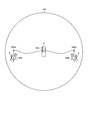
- FIG. 12 is a diagram illustrating an example of the prohibited area 100.
- the processing device 12 changes the size of the prohibited area 100 based on the relative position between the antenna 33A and the antenna 34A.
- the worker WM holding the antenna 34 ⁇ / b> A may move outside the vehicle 3.
- the processing device 12 detects the detection result of the position detection device 33 and the detection result of the position detection device 34 so that both the vehicle 3 and the worker WM moving outside the vehicle 3 are continuously arranged inside the prohibited area 100. Based on the above, the size (dimension) of the prohibited area 100 is changed.
- the processing device 12 updates the prohibited area 100 so that both the vehicle 3 and the worker WM are disposed inside the prohibited area 100.
- the antenna 34 ⁇ / b> A (the worker WM holding the antenna 34 ⁇ / b> A) moves away from the vehicle 3.
- the prohibited area 100 is enlarged.
- the antenna 34A (the worker WM holding the antenna 34A) moves so as to approach the vehicle 3, the prohibited area 100 is reduced.
- the size of the prohibited area 100 may not be changed. Even if the antenna 34A (the worker WM holding the antenna 34A) moves relative to the vehicle 3, if the vehicle 3 and the worker WM are arranged inside the prohibited area 100, the size of the prohibited area 100 is changed. It does not have to be done.
- information on the position (GPS position) of the landmark 8 obtained using the GPS antenna 34A is temporarily stored (held) in the storage device 39 of the vehicle 3.
- the worker WM returns to the inside of the vehicle 3 (boards the vehicle 3) with the antenna 34A being carried.
- the antenna 34 ⁇ / b> A is mounted on the vehicle 3.
- the location registration process for the landmark 8 is performed.
- Information on the position (GPS position) of the landmark 8 obtained using the GPS antenna 34A is registered (stored) in the storage device 13 (database 13B) of the management device 10.
- the input device 31 disposed in the vehicle 3 is operated to register the position of the landmark 8 with respect to the storage device 13.
- the input device 31 functions as an operation unit that can input an operation signal to the processing device 30.
- the worker WM operates the input device 31 to start the location registration process for the landmark 8 (step SB5).
- the input device 31 includes a touch panel.
- the touch panel includes a registration button for instructing the processing device 30 to start the location registration processing of the landmark 8.
- the operation unit includes a registration button.
- the processing device 30 transmits information regarding the position of the landmark 8 temporarily stored in the storage device 39 from the wireless communication device 32.
- the wireless communication device 32 transmits information regarding the position of the landmark 8 to the wireless communication device 18 of the management device 10.
- the wireless communication device 18 outputs the received information regarding the position of the landmark 8 to the processing device 12.
- the processing device 12 registers information on the acquired position (GPS position) of the landmark 8 in the database 13B of the storage device 13 (step SB6).
- the passenger WM may operate the registration button.
- Information regarding the position of the landmark 8 is temporarily stored in the storage device 13 of the management device 10 via the communication system 9, and the storage device 13 is operated by the input device 17 of the management device 10 being operated by the administrator.
- the information regarding the position of the landmark 8 temporarily stored in may be registered in the database 13B.
- the input device 31 disposed on the vehicle 3 is operated.
- the input device 31 functions as an operation unit that can input an operation signal to the processing device 30.
- the worker WM operates the input device 31 in order to end the position detection process for the landmark 8 (step SB7).
- the input device 31 includes a touch panel.
- the touch panel includes an end button for instructing the processing device 30 to end the position detection processing of the landmark 8.
- the operation unit includes an end button. The operator presses (operates) the end button.
- an operation signal is input to the processing device 30.
- the processing device 30 transmits an operation signal input from the operation unit of the input device 31 from the wireless communication device 32.
- the wireless communication device 18 of the management device 10 receives the operation signal from the wireless communication device 32 and outputs it to the processing device 12. After receiving the operation signal from the input device 31, the processing device 12 cancels the setting of the prohibited area 100 including the position of the antenna 34A.
- the worker WM may return to the control facility 7 by operating (driving) the vehicle 3, for example.
- the worker WM may move by operating (driving) the vehicle 3 for position detection processing and position registration processing of another landmark 8.
- the prohibited area 100 including the position of the antenna 33A is continuously set. Therefore, even when the vehicle 3 travels in the mine, the dump truck 2 is prohibited from approaching the vehicle 3.
- the setting of the prohibited area 100 including the position of the antenna 34A may not be canceled after the position detection processing of the landmark 8 is completed.
- the forbidden area 100 is set so as to include the GPS position of the antenna 33A based on the GPS position of the antenna 33A. Is suppressed. Therefore, a decrease in workability of the worker WM boarding the vehicle 3 is suppressed. In addition, the safety of the vehicle 3 (the worker WM boarding the vehicle 3) is ensured. Further, according to the present embodiment, the prohibited area 100 is set so as to include both the GPS position of the antenna 33A and the GPS position of the antenna 34A based on the GPS position of the antenna 33A and the GPS position of the antenna 34A. Therefore, the dump truck 2 is prevented from approaching the antenna 33A (vehicle 3) and the antenna 34A.
- the work using the antenna 34 ⁇ / b> A is performed outside the vehicle 3, it is possible to suppress the workability from being deteriorated. Further, the safety of the worker WM existing inside the prohibited area 100 including the position of the antenna 34A is ensured. Further, since the dump truck 2 does not enter the prohibited area (working area) 100 including the position of the antenna 33A and the prohibited area (working area) 100 including the position of the antenna 34A, for example, as the dump truck 2 approaches. It is suppressed that the work in the prohibited area (work area) 100 is interrupted.
- the position detection device 34 is disposed in the vehicle 3, and the antenna 34 ⁇ / b> A and the position detection device 34 are connected by the cable 35. Both the antenna 34 ⁇ / b> A and the position detection device 34 may be taken out of the vehicle 3.
- the position information may be detected using a portable GPS device in which the antenna 34A and the position detection device 34 are integrated. Since both the antenna 34A and the position detection device 34 can be taken out of the vehicle 3, the cable 35 can be omitted. The same applies to the following embodiments.
- FIG. 13 is a modification of the prohibited area 100.
- the prohibited area 100 includes a prohibited area 100A including the position of the antenna 33A and a prohibited area 100B set apart from the prohibited area 100A and including the position of the antenna 34A.
- the processing device 12 sets the prohibited region 100A so as to include the position of the antenna 33A.
- the processing device 12 sets the prohibited area 100B so as to include the position of the antenna 34A.
- the prohibited area 100A is set so as to include the antenna 33A and the vehicle 3.
- the prohibited area 100B is set to include the antenna 34A, the landmark 8, and the worker WM.
- the processing device 12 transmits a command signal to the dump truck 2 via the communication system 9 so that the dump truck 2 does not enter the prohibited area 100A and the prohibited area 100B.
- the dump truck 2 is prevented from entering the prohibited area 100A and the prohibited area 100B. Therefore, a decrease in workability of work performed inside the prohibited area 100A and a decrease in workability of work performed inside the prohibited area 100B are suppressed. Further, the safety of the worker WM and the vehicle 3 is ensured.
- the processing device 12 may change the position of the prohibited area 100B based on the position of the antenna 34A. For example, when the worker WM moves with the antenna 34A, the prohibited area 100B is moved based on the detection result of the position detection device 34 so that the worker WM and the antenna 34A are continuously arranged inside the prohibited area 100B. Also good. That is, the processing device 12 may move in the prohibited area 100B in synchronization with the antenna 34A (worker WM).
- FIG. 14 shows a modified example of the prohibited area 100.
- the management system 1 includes an antenna 33 ⁇ / b> A disposed in the vehicle 3, an antenna 34 ⁇ / b> Aa that is releasably mounted on the vehicle 3, and an antenna 34 ⁇ / b> Ab that is releasably mounted on the vehicle 3. That is, in the example shown in FIG. 14, an antenna 34Aa and an antenna 34Ab that are portable for the worker WM are provided.
- the processing device 12 determines the position of the antenna 33A (GPS position) and the position of the antenna 34Aa ( The prohibited area 100 may be set so that the GPS position) and the position of the antenna 34Ab (GPS position) are included.
- FIG. 15 shows a modified example of the prohibited area 100.
- the management system 1 includes an antenna 33 ⁇ / b> A disposed in the vehicle 3, an antenna 34 ⁇ / b> Aa that is releasably mounted on the vehicle 3, and an antenna 34 ⁇ / b> Ab that is releasably mounted on the vehicle 3. That is, also in the example shown in FIG. 15, the antenna 34Aa and the antenna 34Ab that can be carried by the worker WM are provided.
- the processing device 12 Based on the position of the antenna 33A (GPS position), the position of the antenna 34a (GPS position), and the position of the antenna 34Ab (GPS position), the processing device 12 includes a prohibited area 100A including the position of the antenna 33A (GPS position)
- the forbidden area 100B is set apart from the forbidden area 100A and includes the position (GPS position) of the antenna 34Aa, and is set apart from each of the forbidden area 100A and the forbidden area 100B and includes the position (GPS position) of the antenna 34Ab.
- Forbidden area 100C may be set.
- the processing device 12 of the control facility 7 acquires the detection result of the position detection device 33 and the position detection result of the position detection device 34 via the communication system 9,
- the example in which the prohibited area 100 is set and the command signal is transmitted to the dump truck 2 has been described.
- the processing device 20 of the dump truck 2 may acquire the detection result of the position detection device 33 and the position detection result of the position detection device 34, and set the prohibited area 100.
- the processing device 20 of the dump truck 2 may control the traveling of the dump truck 2 based on the set prohibited area 100 so that the dump truck 2 does not enter the prohibited area 100.
- the processing device 30 of the vehicle 3 receives the detection result of the position detection device 33 and the position detection result of the position detection device 34 via the communication system 9 (the wireless communication device 28 and the wireless communication device 32). And the prohibited area 100 may be set.
- the processing device 30 of the vehicle 3 may transmit information regarding the set prohibited area 100 to the dump truck 2 via the communication system 9 (the wireless communication device 32 and the wireless communication device 28). That is, the information regarding the prohibited area 100 set by the processing device 30 may be transmitted from the wireless communication device 32 of the vehicle 3 to the wireless communication device 28 of the dump truck 2.
- the processing device 20 of the dump truck 2 may control the traveling of the dump truck 2 so that the dump truck 2 does not enter the prohibited region 100 based on the prohibited region 100 set by the processing device 30 of the vehicle 3. .
- the position detection process of the landmark 8 is performed inside the prohibited area 100.
- the process (work) performed inside the prohibited area 100 is not limited to the position detection process of the landmark 8.
- the maintenance work of the conveyance path HL may be performed inside the prohibited area 100 set based on the antenna 34A, or the repair work of the equipment may be performed. Even in this case, by setting the prohibition area (work area) 100 so as to include the position of the antenna 34A, the safety of the worker WM is ensured and the deterioration of workability is suppressed.
- the workability of work inside the prohibited area (work area) 100 is set by setting the prohibited area (work area) 100 so as to include the position of the antenna 34A. Is suppressed.
- a mining machine for example, a motor grader
- the prohibited area 100 is included so that the mining machine is included so that the work using the mining machine is performed smoothly. May be installed.
- the dump truck 2 it is not necessary to stop the operation of the dump truck 2 by operating the mining machine inside the prohibited area 100. That is, by placing the mining machine inside the prohibited area 100, the dump truck 2 can be operated in parallel with the operation of the mining machine. Therefore, a decrease in workability and a decrease in productivity in the mine are suppressed.
- the dump truck 2 may be a so-called manned dump truck that is operated by an operator (driver) operation.
- the communication system 9 may transmit a command signal so that the dump truck (manned dump truck) 2 does not enter the prohibited area 100.
- the communication system 9 may transmit a command signal including an alarm (warning) to the dump truck 2 approaching the prohibited area 100, for example.
- Management system Dump truck (mining equipment) 3 vehicle 4 loading machine 9 communication system 10 management device 12 processing device 13 storage device 18 wireless communication device 20 processing device 25 storage device 28 wireless communication device 29 position detection device 29A antenna 30 processing device 31 input device 32 wireless communication device 33 position Detection device 33A Antenna 34 Position detection device 34A Antenna 39 Storage device 100 Forbidden area DPA Excavation field HL Transport path LPA Loading field
Landscapes
- Engineering & Computer Science (AREA)
- Radar, Positioning & Navigation (AREA)
- Remote Sensing (AREA)
- Aviation & Aerospace Engineering (AREA)
- Physics & Mathematics (AREA)
- General Physics & Mathematics (AREA)
- Automation & Control Theory (AREA)
- Traffic Control Systems (AREA)
- Fittings On The Vehicle Exterior For Carrying Loads, And Devices For Holding Or Mounting Articles (AREA)
- Control Of Position, Course, Altitude, Or Attitude Of Moving Bodies (AREA)
Abstract
Description
図1は、本実施形態に係る鉱山機械の管理システム1の一例を示す図である。図1は、管理システム1及び管理システム1が適用される現場を模式的に示す。
次に、管制施設7に配置される管理装置10について説明する。図2は、本実施形態に係る管理装置10の一例を示すブロック図である。図1及び図2に示すように、管理装置10は、コンピュータシステム11と、表示装置16と、入力装置17と、無線通信装置18と、を備えている。
次に、ダンプトラック2について説明する。図3は、本実施形態に係るダンプトラック2の外観を模式的に示す図である。図4は、本実施形態に係るダンプトラック2の制御ブロック図である。
次に、車両3について説明する。図5は、本実施形態に係る車両3の外観を模式的に示す図である。図6は、本実施形態に係る車両3の制御ブロック図である。
次に、ランドマーク8の使用方法について説明する。図7は、ダンプトラック2の非接触センサ24によりランドマーク8が検出されている状態の一例を模式的に示す図である。ランドマーク8は、積込場LPA、排土場DPA、及び搬送路HLのそれぞれに配置される。搬送路HLにおいては、ランドマーク8は、搬送路HLの外側(路肩)に配置される。ランドマーク8は、搬送路HLに沿って間隔をあけて複数配置される。ランドマーク8は、例えば100m毎に配置されてもよい。
次に、本実施形態に係るダンプトラック2の走行方法の一例について説明する。処理装置12は、通信システム9(無線通信装置18及び無線通信装置28)を介して、ダンプトラック2の処理装置20(走行制御部20D)に指令信号を送信する。指令信号は、ダンプトラック2の走行条件に関する情報を含む。走行条件に関する情報は、処理装置12で生成された走行経路に関する情報、及びダンプトラック2の走行速度に関する情報を含む。処理装置20(走行制御部20D)は、通信システム9を介して送信された処理装置12からの指令信号に基づいて、ダンプトラック2の操作(ステアリング、アクセル、及びブレーキの少なくとも一つの操作)を制御して、ダンプトラック2の走行を制御する。
次に、ランドマーク8の位置検出処理及び位置登録処理(図8のステップSA1の処理)の一例について説明する。ランドマーク8の位置検出処理は、ランドマーク8のGPS位置を検出する処理である。ランドマーク8の位置登録処理は、検出されたランドマーク8のGPS位置(GPS位置に関する情報)を記憶装置13(データベース13B)に登録(記憶)する処理である。なお、ランドマーク8のGPS位置が、ダンプトラック2の記憶装置25(データベース25B)に登録されてもよい。
次に、図9を参照して説明したランドマーク8の位置検出処理及び位置登録処理において、アンテナ34Aの位置を含むようにダンプトラック2の進入を禁止する禁止領域100が設定される例について説明する。
図13は、禁止領域100の変形例である。図13において、禁止領域100は、アンテナ33Aの位置を含む禁止領域100Aと、禁止領域100Aから離れて設定され、アンテナ34Aの位置を含む禁止領域100Bとを含む。処理装置12は、位置検出装置33の検出結果に基づいて、アンテナ33Aの位置を含むように、禁止領域100Aを設定する。処理装置12は、位置検出装置34の検出結果に基づいて、アンテナ34Aの位置を含むように、禁止領域100Bを設定する。禁止領域100Aは、アンテナ33A及び車両3を含むように設定される。禁止領域100Bは、アンテナ34A、ランドマーク8、及び作業者WMを含むように設定される。処理装置12は、通信システム9を介して、禁止領域100A及び禁止領域100Bにダンプトラック2が進入しないように、ダンプトラック2に指令信号を送信する。これにより、ダンプトラック2が禁止領域100A及び禁止領域100Bの内側に進入することが抑制される。したがって、禁止領域100Aの内側で行われる作業の作業性の低下、及び禁止領域100Bの内側で行われる作業の作業性の低下が抑制される。また、作業者WM及び車両3の安全が確保される。
図14は、禁止領域100の変形例である。図14において、管理システム1は、車両3に配置されたアンテナ33Aと、車両3にリリース可能に搭載されたアンテナ34Aaと、車両3にリリース可能に搭載されたアンテナ34Abとを備えている。すなわち、図14に示す例においては、作業者WMが携帯可能なアンテナ34Aa及びアンテナ34Abが設けられる。処理装置12は、アンテナ33Aの位置(GPS位置)、アンテナ34aの位置(GPS位置)、及びアンテナ34Abの位置(GPS位置)に基づいて、アンテナ33Aの位置(GPS位置)、アンテナ34Aaの位置(GPS位置)、及びアンテナ34Abの位置(GPS位置)が含まれるように、禁止領域100を設定してもよい。
2 ダンプトラック(鉱山機械)
3 車両
4 積込機械
9 通信システム
10 管理装置
12 処理装置
13 記憶装置
18 無線通信装置
20 処理装置
25 記憶装置
28 無線通信装置
29 位置検出装置
29A アンテナ
30 処理装置
31 入力装置
32 無線通信装置
33 位置検出装置
33A アンテナ
34 位置検出装置
34A アンテナ
39 記憶装置
100 禁止領域
DPA 排土場
HL 搬送路
LPA 積込場
Claims (15)
- 鉱山を走行可能な車両と、
前記車両に配置され、GPS衛星からの電波を受信する第1アンテナと、
前記車両にリリース可能に搭載され、GPS衛星からの電波を受信する携帯可能な第2アンテナと、
前記車両に配置され、前記第1アンテナからの信号に基づいて前記第1アンテナの位置を検出する第1検出装置と、
前記第2アンテナからの信号に基づいて前記第2アンテナの位置を検出する第2検出装置と、
前記第1検出装置の検出結果及び前記第2検出装置の検出結果に基づいて、前記第1アンテナの位置及び前記第2アンテナの位置を含むように、前記鉱山を走行可能な鉱山機械の進入を禁止する禁止領域を設定する処理装置と、を備える鉱山機械の管理システム。 - 前記第2検出装置は、前記車両に配置され、
前記第2アンテナは、前記車両の外側に配置された状態で、GPS衛星からの電波を受信する請求項1に記載の鉱山機械の管理システム。 - 前記第2アンテナは、前記車両に搭乗した作業者に携帯されたものである請求項1又は請求項2に記載の鉱山機械の管理システム。
- 前記車両に配置され、前記処理装置に信号を入力可能な操作部を備え、
前記操作部が操作されることにより、前記第2アンテナの位置を含む前記禁止領域の設定及び設定解除の少なくとも一方が行われる請求項1から請求項3のいずれか一項に記載の鉱山機械の管理システム。 - 前記鉱山機械は、前記鉱山における積込場と、排土場と、前記積込場及び前記排土場の少なくとも一方に通じる搬送路の少なくとも一部において稼動され、
前記鉱山機械の稼動中において、前記第1アンテナの位置を含むように前記禁止領域が設定され続ける請求項1から請求項4のいずれか一項に記載の鉱山機械の管理システム。 - 前記禁止領域は、前記第1アンテナの位置及び前記第2アンテナの位置の両方を含む1つの領域である請求項1から請求項5のいずれか一項に記載の鉱山機械の管理システム。
- 前記処理装置は、前記第1アンテナと前記第2アンテナとの相対位置に基づいて、前記禁止領域の大きさを変える請求項6に記載の鉱山機械の管理システム。
- 前記禁止領域は、前記第1アンテナの位置を含む第1禁止領域と、前記第1禁止領域から離れて設定され、前記第2アンテナの位置を含む第2禁止領域と、を含む請求項1から請求項5のいずれか一項に記載の鉱山機械の管理システム。
- 前記禁止領域に前記鉱山機械が進入しないように前記鉱山機械に指令信号を送信する通信システムを備える請求項1から請求項8のいずれか一項に記載の鉱山機械の管理システム。
- 前記通信システムは、前記車両に搭載され、前記第1アンテナ及び前記第2アンテナそれぞれからの信号に基づく情報を送信可能な第1通信装置を含む請求項9に記載の鉱山機械の管理システム。
- 前記信号に基づく情報は、前記第1検出装置により検出された前記第1アンテナの位置に関する情報、及び前記第2検出装置により検出された前記第2アンテナの位置に関する情報を含む請求項10に記載の鉱山機械の管理システム。
- 前記処理装置を有する管制施設を備え、
前記管制施設の前記処理装置が、前記第1通信装置からの前記信号に基づく情報に基づいて、前記禁止領域を設定し、
前記通信システムは、前記管制施設に配置された第2通信装置と、前記鉱山機械に配置された第3通信装置と、を含み、
前記第2通信装置から前記第3通信装置に前記指令信号が送信される請求項11に記載の鉱山機械の管理システム。 - 管制施設に配置された中央管制装置を有する鉱山機械の管理システムであって、
鉱山を走行可能な車両と、
前記車両に配置され、GPS衛星からの電波を受信する第1アンテナと、
前記車両にリリース可能に搭載され、前記車両の外側において前記車両に搭乗した作業者に携帯された状態で、GPS衛星からの電波を受信する携帯可能な第2アンテナと、
前記車両に配置され、前記第1アンテナからの信号に基づいて前記第1アンテナの位置を検出する第1検出装置と、
前記車両に配置され、前記第2アンテナからの信号に基づいて前記第2アンテナの位置を検出する第2検出装置と、
前記中央管制装置に設けられ、前記第1検出装置の検出結果及び前記第2検出装置の検出結果に基づいて、前記第1アンテナの位置及び前記第2アンテナの位置を含むように、前記鉱山を走行可能な鉱山機械の進入を禁止する禁止領域を設定するとともに、前記鉱山機械の走行において前記禁止領域の手前で停止するように前記鉱山機械の走行条件を設定する処理装置と、
前記処理装置で設定された前記走行条件に関する情報を前記鉱山機械に送信する通信システムと、を備え、
前記鉱山機械は、前記中央管制装置から前記通信システムによって送信された前記走行条件に関する情報に従って、前記鉱山を走行する鉱山機械の管理システム。 - 鉱山を走行可能な車両に配置された第1アンテナで、GPS衛星からの電波を受信することと、
前記車両にリリース可能に搭載された携帯可能な第2アンテナで、GPS衛星からの電波を受信することと、
前記第1アンテナからの信号に基づいて前記第1アンテナの位置を検出することと、
前記第2アンテナからの信号に基づいて前記第2アンテナの位置を検出することと、
前記検出の結果に基づいて、前記第1アンテナの位置及び前記第2アンテナの位置を含むように、前記鉱山を走行可能な鉱山機械の進入を禁止する禁止領域を設定することと、を含む鉱山機械の管理方法。 - 管制施設に配置された中央管制装置を用いる鉱山機械の管理方法であって、
鉱山を走行可能な車両に配置された第1アンテナで、GPS衛星からの電波を受信することと、
前記車両にリリース可能に搭載され、前記車両の外側において前記車両に搭乗した作業者に携帯された第2アンテナで、GPS衛星からの電波を受信することと、
前記第1アンテナからの信号に基づいて前記第1アンテナの位置を検出することと、
前記第2アンテナからの信号に基づいて前記第2アンテナの位置を検出することと、
前記検出の結果に基づいて、前記第1アンテナの位置及び前記第2アンテナの位置を含むように、前記鉱山を走行可能な鉱山機械の進入を禁止する禁止領域を設定すること、及び前記鉱山機械の走行において前記禁止領域の手前で停止するように前記鉱山機械の走行条件を設定することを、前記中央管制装置に設けられた処理装置で行うことと、
前記処理装置で設定された前記走行条件に関する情報を前記鉱山機械に送信することと、
前記中央管制装置から送信された前記走行条件に関する情報に従って、前記鉱山機械を走行させることと、を含む鉱山機械の管理方法。
Priority Applications (6)
| Application Number | Priority Date | Filing Date | Title |
|---|---|---|---|
| CA2849465A CA2849465C (en) | 2013-07-30 | 2013-07-30 | Management system and management method of mining machine |
| US14/355,000 US10671089B2 (en) | 2013-07-30 | 2013-07-30 | Management system and management method of mining machine |
| AU2013337237A AU2013337237B2 (en) | 2013-07-30 | 2013-07-30 | Management system and management method of mining machine |
| JP2013549456A JP5607841B1 (ja) | 2013-07-30 | 2013-07-30 | 鉱山機械の管理システム及び管理方法 |
| CN201380003654.3A CN104487996A (zh) | 2013-07-30 | 2013-07-30 | 矿山机械的管理系统以及管理方法 |
| PCT/JP2013/070665 WO2015015575A1 (ja) | 2013-07-30 | 2013-07-30 | 鉱山機械の管理システム及び管理方法 |
Applications Claiming Priority (1)
| Application Number | Priority Date | Filing Date | Title |
|---|---|---|---|
| PCT/JP2013/070665 WO2015015575A1 (ja) | 2013-07-30 | 2013-07-30 | 鉱山機械の管理システム及び管理方法 |
Publications (1)
| Publication Number | Publication Date |
|---|---|
| WO2015015575A1 true WO2015015575A1 (ja) | 2015-02-05 |
Family
ID=51840533
Family Applications (1)
| Application Number | Title | Priority Date | Filing Date |
|---|---|---|---|
| PCT/JP2013/070665 Ceased WO2015015575A1 (ja) | 2013-07-30 | 2013-07-30 | 鉱山機械の管理システム及び管理方法 |
Country Status (6)
| Country | Link |
|---|---|
| US (1) | US10671089B2 (ja) |
| JP (1) | JP5607841B1 (ja) |
| CN (1) | CN104487996A (ja) |
| AU (1) | AU2013337237B2 (ja) |
| CA (1) | CA2849465C (ja) |
| WO (1) | WO2015015575A1 (ja) |
Cited By (5)
| Publication number | Priority date | Publication date | Assignee | Title |
|---|---|---|---|---|
| WO2016039489A1 (ja) * | 2015-10-30 | 2016-03-17 | 株式会社小松製作所 | 鉱山の管理システム及び鉱山の管理方法 |
| WO2016056677A1 (ja) * | 2015-10-30 | 2016-04-14 | 株式会社小松製作所 | 鉱山の管理システム及び鉱山の管理方法 |
| AU2016204168B2 (en) * | 2016-02-01 | 2017-11-09 | Komatsu Ltd. | Work machine control system, work machine, and work machine management system |
| CN109801486A (zh) * | 2019-01-31 | 2019-05-24 | 北京永安信通科技股份有限公司 | 矿井车辆交通系统、车辆信息监控装置和车载信息定位装置 |
| WO2022080422A1 (ja) * | 2020-10-14 | 2022-04-21 | 株式会社小松製作所 | 無人車両の制御システム、無人車両、及び無人車両の制御方法 |
Families Citing this family (15)
| Publication number | Priority date | Publication date | Assignee | Title |
|---|---|---|---|---|
| JP6575066B2 (ja) * | 2015-01-16 | 2019-09-18 | 富士通株式会社 | 道路工事計画プログラム、道路工事計画方法および情報処理装置 |
| CA2945926C (en) * | 2016-02-29 | 2018-09-25 | Komatsu Ltd. | Control system for work machine, work machine, and management system for work machine |
| AU2016205662A1 (en) | 2016-03-31 | 2017-10-19 | Komatsu Ltd. | Work vehicle control system |
| CA3106117A1 (en) * | 2018-07-23 | 2020-01-30 | Newtrax Holdings Inc. | Method and system for acknowledging presence in a context-aware environment |
| CN109398304A (zh) * | 2018-12-07 | 2019-03-01 | 安徽华菱汽车有限公司 | 一种纯电动自卸车及其监控方法、系统及装置 |
| CN109763824A (zh) * | 2019-01-24 | 2019-05-17 | 本钢板材股份有限公司 | 一种卫星定位动态配矿方法 |
| CN110053573A (zh) * | 2019-05-09 | 2019-07-26 | 贵州理工学院 | 一种露天矿山卡车智能无人驾驶和调度系统 |
| US11703859B2 (en) | 2019-07-05 | 2023-07-18 | Liebherr Mining Equipment Newport News Co. | Method for autonomously controlling a vehicle |
| US11214944B2 (en) | 2019-09-12 | 2022-01-04 | Jim D. Wiethorn | Heavy equipment hazard warning apparatus and system and method for use of same |
| US11892836B2 (en) | 2020-01-27 | 2024-02-06 | Liebherr Mining Equipment Newport News Co. | System for controlling a plurality of autonomous vehicles on a mine site |
| US11288897B2 (en) | 2020-08-20 | 2022-03-29 | Jim D. Wiethorn | Crane risk logic apparatus and system and method for use of same |
| EP3964911B1 (en) * | 2020-09-03 | 2023-08-02 | Volvo Autonomous Solutions AB | A method of controlling the working scheme of an autonomous working machine at a worksite |
| JP7580423B2 (ja) * | 2022-04-22 | 2024-11-11 | 株式会社小松製作所 | 作業現場の管理システム及び作業現場の管理方法 |
| US11521138B1 (en) | 2022-06-27 | 2022-12-06 | Freeport Minerals Corporation | System and method for adjusting leaching operations based on leach analytic data |
| CN116864968A (zh) * | 2023-05-26 | 2023-10-10 | 华能伊敏煤电有限责任公司 | 一种无人驾驶宽体矿车卫星天线调节控制方法及系统 |
Citations (4)
| Publication number | Priority date | Publication date | Assignee | Title |
|---|---|---|---|---|
| JPH11160068A (ja) * | 1997-11-27 | 1999-06-18 | Kajima Corp | Gps利用の移動体安全管理システム |
| JP2001262627A (ja) * | 2000-03-17 | 2001-09-26 | Komatsu Ltd | 移動体の始動ロック装置 |
| JP2003105807A (ja) * | 2001-09-27 | 2003-04-09 | Komatsu Ltd | 作業車両の侵入禁止領域での停止制御方法及びその制御装置 |
| JP2005182667A (ja) * | 2003-12-22 | 2005-07-07 | Chugoku Electric Power Co Inc:The | Gps利用無線式接近警報装置 |
Family Cites Families (24)
| Publication number | Priority date | Publication date | Assignee | Title |
|---|---|---|---|---|
| ZA952853B (en) * | 1994-04-18 | 1995-12-21 | Caterpillar Inc | Method and apparatus for real time monitoring and co-ordination of multiple geography altering machines on a work site |
| US6292725B1 (en) * | 1997-04-04 | 2001-09-18 | Komatsu Ltd. | Interference preventing device for vehicle |
| US5987379A (en) * | 1997-10-30 | 1999-11-16 | Trimble Navigation Limited | Creation and monitoring of variable buffer zones |
| JP2000339028A (ja) * | 1999-05-31 | 2000-12-08 | Komatsu Ltd | 移動局のデータ共有装置 |
| US6393362B1 (en) * | 2000-03-07 | 2002-05-21 | Modular Mining Systems, Inc. | Dynamic safety envelope for autonomous-vehicle collision avoidance system |
| CA2571326A1 (en) * | 2004-06-21 | 2006-01-26 | Fuller Bros, Inc. | Vehicle safety zone system |
| US7062381B1 (en) * | 2005-08-30 | 2006-06-13 | Deere & Company | Method and system for determining relative position of mobile vehicles |
| JP2007272487A (ja) * | 2006-03-31 | 2007-10-18 | Tcm Corp | 作業エリアにおける相対位置認識システム |
| US20090043462A1 (en) * | 2007-06-29 | 2009-02-12 | Kenneth Lee Stratton | Worksite zone mapping and collision avoidance system |
| US7468695B1 (en) * | 2007-07-19 | 2008-12-23 | Raytheon Company | GPS attitude determination system and method using baseline extension |
| US8095248B2 (en) * | 2007-09-04 | 2012-01-10 | Modular Mining Systems, Inc. | Method and system for GPS based navigation and hazard avoidance in a mining environment |
| US8280621B2 (en) * | 2008-04-15 | 2012-10-02 | Caterpillar Inc. | Vehicle collision avoidance system |
| US8639408B2 (en) * | 2008-10-15 | 2014-01-28 | Deere & Company | High integrity coordination system for multiple off-road vehicles |
| JP5061084B2 (ja) | 2008-11-13 | 2012-10-31 | 日立建機株式会社 | 現場内監視システム |
| DE112009004342B4 (de) * | 2009-02-19 | 2012-12-13 | Toyota Jidosha K.K. | Mobilobjektpositionserfassungsvorrichtung |
| JP5369057B2 (ja) * | 2010-06-18 | 2013-12-18 | 日立建機株式会社 | 作業機械の周囲監視装置 |
| WO2011158955A1 (ja) * | 2010-06-18 | 2011-12-22 | 日立建機株式会社 | 作業機械の周囲監視装置 |
| US8477021B2 (en) * | 2010-10-25 | 2013-07-02 | John Slack | Worksite proximity warning and collision avoidance system |
| CN103890282A (zh) * | 2011-10-18 | 2014-06-25 | 日立建机株式会社 | 作业机械的周围监视装置 |
| JP5535176B2 (ja) | 2011-11-04 | 2014-07-02 | 株式会社小松製作所 | 鉱山機械の動態管理システム |
| JP5596661B2 (ja) | 2011-11-11 | 2014-09-24 | 株式会社小松製作所 | 鉱山機械の管理システム及び鉱山機械の管理システムの管理方法 |
| EP2955914B1 (en) * | 2013-02-08 | 2018-10-17 | Hitachi Construction Machinery Co., Ltd. | Surroundings monitoring device for slewing-type work machine |
| US9110454B2 (en) * | 2013-02-14 | 2015-08-18 | Caterpillar Inc. | Machine detection system |
| AU2014297425A1 (en) * | 2013-07-29 | 2015-09-24 | Hitachi Construction Machinery Co., Ltd. | Relative position computation system for working machine |
-
2013
- 2013-07-30 CA CA2849465A patent/CA2849465C/en active Active
- 2013-07-30 CN CN201380003654.3A patent/CN104487996A/zh active Pending
- 2013-07-30 JP JP2013549456A patent/JP5607841B1/ja active Active
- 2013-07-30 WO PCT/JP2013/070665 patent/WO2015015575A1/ja not_active Ceased
- 2013-07-30 US US14/355,000 patent/US10671089B2/en active Active
- 2013-07-30 AU AU2013337237A patent/AU2013337237B2/en not_active Ceased
Patent Citations (4)
| Publication number | Priority date | Publication date | Assignee | Title |
|---|---|---|---|---|
| JPH11160068A (ja) * | 1997-11-27 | 1999-06-18 | Kajima Corp | Gps利用の移動体安全管理システム |
| JP2001262627A (ja) * | 2000-03-17 | 2001-09-26 | Komatsu Ltd | 移動体の始動ロック装置 |
| JP2003105807A (ja) * | 2001-09-27 | 2003-04-09 | Komatsu Ltd | 作業車両の侵入禁止領域での停止制御方法及びその制御装置 |
| JP2005182667A (ja) * | 2003-12-22 | 2005-07-07 | Chugoku Electric Power Co Inc:The | Gps利用無線式接近警報装置 |
Cited By (15)
| Publication number | Priority date | Publication date | Assignee | Title |
|---|---|---|---|---|
| AU2015319797C1 (en) * | 2015-10-30 | 2018-08-16 | Komatsu Ltd. | Mine management system and mine management method |
| WO2016056677A1 (ja) * | 2015-10-30 | 2016-04-14 | 株式会社小松製作所 | 鉱山の管理システム及び鉱山の管理方法 |
| JP6030778B2 (ja) * | 2015-10-30 | 2016-11-24 | 株式会社小松製作所 | 鉱山の管理システム及び鉱山の管理方法 |
| US9595196B1 (en) | 2015-10-30 | 2017-03-14 | Komatsu Ltd. | Mine management system and mine managing method |
| US9593463B1 (en) | 2015-10-30 | 2017-03-14 | Komatsu Ltd. | Mine management system and mine managing method |
| JPWO2016039489A1 (ja) * | 2015-10-30 | 2017-04-27 | 株式会社小松製作所 | 鉱山の管理システム及び鉱山の管理方法 |
| WO2016039489A1 (ja) * | 2015-10-30 | 2016-03-17 | 株式会社小松製作所 | 鉱山の管理システム及び鉱山の管理方法 |
| US9828748B2 (en) | 2015-10-30 | 2017-11-28 | Komatsu Ltd. | Mine management system and mine managing method |
| AU2015319797B2 (en) * | 2015-10-30 | 2018-03-01 | Komatsu Ltd. | Mine management system and mine management method |
| AU2016204168B2 (en) * | 2016-02-01 | 2017-11-09 | Komatsu Ltd. | Work machine control system, work machine, and work machine management system |
| US10031528B2 (en) | 2016-02-01 | 2018-07-24 | Komatsu Ltd. | Work machine control system, work machine, and work machine management system |
| CN109801486A (zh) * | 2019-01-31 | 2019-05-24 | 北京永安信通科技股份有限公司 | 矿井车辆交通系统、车辆信息监控装置和车载信息定位装置 |
| WO2022080422A1 (ja) * | 2020-10-14 | 2022-04-21 | 株式会社小松製作所 | 無人車両の制御システム、無人車両、及び無人車両の制御方法 |
| JP2022064545A (ja) * | 2020-10-14 | 2022-04-26 | 株式会社小松製作所 | 無人車両の制御システム、無人車両、及び無人車両の制御方法 |
| JP7668629B2 (ja) | 2020-10-14 | 2025-04-25 | 株式会社小松製作所 | 無人車両の制御システム、無人車両、及び無人車両の制御方法 |
Also Published As
| Publication number | Publication date |
|---|---|
| CA2849465C (en) | 2016-12-20 |
| US20160224029A1 (en) | 2016-08-04 |
| AU2013337237A1 (en) | 2015-02-19 |
| CA2849465A1 (en) | 2015-01-30 |
| AU2013337237B2 (en) | 2015-11-05 |
| JP5607841B1 (ja) | 2014-10-15 |
| CN104487996A (zh) | 2015-04-01 |
| US10671089B2 (en) | 2020-06-02 |
| JPWO2015015575A1 (ja) | 2017-03-02 |
Similar Documents
| Publication | Publication Date | Title |
|---|---|---|
| JP5607841B1 (ja) | 鉱山機械の管理システム及び管理方法 | |
| JP5714129B1 (ja) | 鉱山機械の管理システム及び管理方法 | |
| JP6475169B2 (ja) | 鉱山機械の管理システム、鉱山機械及び管理方法 | |
| US10599158B2 (en) | Mining machine management system and management method | |
| JP6412884B2 (ja) | 鉱山機械の管理システム及び管理方法 | |
| JP6271023B2 (ja) | 作業機械の制御システム、作業機械及び作業機械の制御方法 | |
| CA3010702A1 (en) | Work machine management system and work machine |
Legal Events
| Date | Code | Title | Description |
|---|---|---|---|
| ENP | Entry into the national phase |
Ref document number: 2013549456 Country of ref document: JP Kind code of ref document: A |
|
| WWE | Wipo information: entry into national phase |
Ref document number: 2849465 Country of ref document: CA |
|
| WWE | Wipo information: entry into national phase |
Ref document number: 14355000 Country of ref document: US |
|
| WWE | Wipo information: entry into national phase |
Ref document number: 2013337237 Country of ref document: AU |
|
| 121 | Ep: the epo has been informed by wipo that ep was designated in this application |
Ref document number: 13890312 Country of ref document: EP Kind code of ref document: A1 |
|
| NENP | Non-entry into the national phase |
Ref country code: DE |
|
| 122 | Ep: pct application non-entry in european phase |
Ref document number: 13890312 Country of ref document: EP Kind code of ref document: A1 |