WO2015012349A1 - 炭素化方法及び炭素繊維の製造方法 - Google Patents
炭素化方法及び炭素繊維の製造方法 Download PDFInfo
- Publication number
- WO2015012349A1 WO2015012349A1 PCT/JP2014/069552 JP2014069552W WO2015012349A1 WO 2015012349 A1 WO2015012349 A1 WO 2015012349A1 JP 2014069552 W JP2014069552 W JP 2014069552W WO 2015012349 A1 WO2015012349 A1 WO 2015012349A1
- Authority
- WO
- WIPO (PCT)
- Prior art keywords
- carbonization
- fiber
- furnace
- plasma
- carbonization furnace
- Prior art date
- Legal status (The legal status is an assumption and is not a legal conclusion. Google has not performed a legal analysis and makes no representation as to the accuracy of the status listed.)
- Ceased
Links
Images


Classifications
-
- D—TEXTILES; PAPER
- D01—NATURAL OR MAN-MADE THREADS OR FIBRES; SPINNING
- D01F—CHEMICAL FEATURES IN THE MANUFACTURE OF ARTIFICIAL FILAMENTS, THREADS, FIBRES, BRISTLES OR RIBBONS; APPARATUS SPECIALLY ADAPTED FOR THE MANUFACTURE OF CARBON FILAMENTS
- D01F9/00—Artificial filaments or the like of other substances; Manufacture thereof; Apparatus specially adapted for the manufacture of carbon filaments
- D01F9/08—Artificial filaments or the like of other substances; Manufacture thereof; Apparatus specially adapted for the manufacture of carbon filaments of inorganic material
- D01F9/12—Carbon filaments; Apparatus specially adapted for the manufacture thereof
- D01F9/14—Carbon filaments; Apparatus specially adapted for the manufacture thereof by decomposition of organic filaments
- D01F9/20—Carbon filaments; Apparatus specially adapted for the manufacture thereof by decomposition of organic filaments from polyaddition, polycondensation or polymerisation products
- D01F9/21—Carbon filaments; Apparatus specially adapted for the manufacture thereof by decomposition of organic filaments from polyaddition, polycondensation or polymerisation products from macromolecular compounds obtained by reactions only involving carbon-to-carbon unsaturated bonds
- D01F9/22—Carbon filaments; Apparatus specially adapted for the manufacture thereof by decomposition of organic filaments from polyaddition, polycondensation or polymerisation products from macromolecular compounds obtained by reactions only involving carbon-to-carbon unsaturated bonds from polyacrylonitriles
-
- D—TEXTILES; PAPER
- D01—NATURAL OR MAN-MADE THREADS OR FIBRES; SPINNING
- D01F—CHEMICAL FEATURES IN THE MANUFACTURE OF ARTIFICIAL FILAMENTS, THREADS, FIBRES, BRISTLES OR RIBBONS; APPARATUS SPECIALLY ADAPTED FOR THE MANUFACTURE OF CARBON FILAMENTS
- D01F9/00—Artificial filaments or the like of other substances; Manufacture thereof; Apparatus specially adapted for the manufacture of carbon filaments
- D01F9/08—Artificial filaments or the like of other substances; Manufacture thereof; Apparatus specially adapted for the manufacture of carbon filaments of inorganic material
- D01F9/12—Carbon filaments; Apparatus specially adapted for the manufacture thereof
- D01F9/14—Carbon filaments; Apparatus specially adapted for the manufacture thereof by decomposition of organic filaments
-
- C—CHEMISTRY; METALLURGY
- C01—INORGANIC CHEMISTRY
- C01B—NON-METALLIC ELEMENTS; COMPOUNDS THEREOF; METALLOIDS OR COMPOUNDS THEREOF NOT COVERED BY SUBCLASS C01C
- C01B32/00—Carbon; Compounds thereof
- C01B32/05—Preparation or purification of carbon not covered by groups C01B32/15, C01B32/20, C01B32/25, C01B32/30
-
- C—CHEMISTRY; METALLURGY
- C01—INORGANIC CHEMISTRY
- C01B—NON-METALLIC ELEMENTS; COMPOUNDS THEREOF; METALLOIDS OR COMPOUNDS THEREOF NOT COVERED BY SUBCLASS C01C
- C01B32/00—Carbon; Compounds thereof
- C01B32/25—Diamond
- C01B32/26—Preparation
-
- D—TEXTILES; PAPER
- D01—NATURAL OR MAN-MADE THREADS OR FIBRES; SPINNING
- D01F—CHEMICAL FEATURES IN THE MANUFACTURE OF ARTIFICIAL FILAMENTS, THREADS, FIBRES, BRISTLES OR RIBBONS; APPARATUS SPECIALLY ADAPTED FOR THE MANUFACTURE OF CARBON FILAMENTS
- D01F9/00—Artificial filaments or the like of other substances; Manufacture thereof; Apparatus specially adapted for the manufacture of carbon filaments
- D01F9/08—Artificial filaments or the like of other substances; Manufacture thereof; Apparatus specially adapted for the manufacture of carbon filaments of inorganic material
- D01F9/12—Carbon filaments; Apparatus specially adapted for the manufacture thereof
- D01F9/14—Carbon filaments; Apparatus specially adapted for the manufacture thereof by decomposition of organic filaments
- D01F9/32—Apparatus therefor
-
- D—TEXTILES; PAPER
- D10—INDEXING SCHEME ASSOCIATED WITH SUBLASSES OF SECTION D, RELATING TO TEXTILES
- D10B—INDEXING SCHEME ASSOCIATED WITH SUBLASSES OF SECTION D, RELATING TO TEXTILES
- D10B2101/00—Inorganic fibres
- D10B2101/10—Inorganic fibres based on non-oxides other than metals
- D10B2101/12—Carbon; Pitch
Definitions
- the present invention relates to a method for carbonizing precursor fibers and a method for producing carbon fibers.
- Carbon fiber is produced by firing a precursor fiber produced from polyacrylonitrile fiber, rayon fiber, cellulose fiber, pitch fiber or the like.
- firing of a precursor fiber manufactured from polyacrylonitrile fiber is referred to as a flame-proofing step in which the precursor fiber is heated in an oxygen-containing atmosphere (in a flameproofing furnace) and a fiber that has undergone a flameproofing step (hereinafter referred to as “flameproof fiber”).
- flameproof fiber a flame-proofing step in which the precursor fiber is heated in an oxygen-containing atmosphere (in a flameproofing furnace) and a fiber that has undergone a flameproofing step (hereinafter referred to as “flameproof fiber”).
- flameproof fiber a fiber that has undergone a flameproofing step
- carbonization furnace Through a carbonization step of heating in an inert atmosphere (carbonization furnace).
- the said baking is performed because a fiber passes (runs) through a flame-proofing furnace and a carbonization furnace.
- the heating in the carbonization process uses an electric heater or the like. That is, the flame resistant fiber is indirectly heated by heating the furnace atmosphere with an electric heater or the like and passing the flame resistant fiber through the heated furnace. In this case, it is necessary to heat the entire inside of the furnace, so that the heating efficiency to the flame resistant fiber is low (low heating efficiency), and the heat in the furnace is gradually transmitted from the outside to the inside of the flame resistant fiber bundle. It takes time (longer time).
- a direct heating method for example, a method using microwaves (for example, Patent Documents 2 and 3), a method using plasma (for example, Patent Document 4), a method using both microwaves and plasma (for example, Patent Document 5), a method using high-frequency electromagnetic waves (for example, Patent Document 6), and the like.
- Patent Documents 2 to 4 heat the flame resistant fiber having a predetermined length in a container or the like, and cannot be applied to the flame resistant fiber traveling in the furnace.
- the present invention provides a carbonization method and a carbon fiber production method capable of applying a tension suitable for the state of the fiber during the carbon process while shortening the carbonization time with high heating efficiency.
- the purpose is to provide.
- a carbonization method includes a carbonization method for carbonizing a precursor fiber that is running, wherein a plurality of carbonization furnaces for heating the fiber exist in the running direction.
- a plurality of carbonization furnaces for heating the fiber exist in the running direction.
- at least one carbonization furnace is characterized in that the fiber passing through the furnace is heated using plasma.
- the manufacturing method of the carbon fiber which concerns on 1 aspect of this invention is a carbon fiber manufacturing method including the carbonization process of carbonizing the precursor fiber in driving
- the said carbonization process Is characterized by being performed by the carbonization method described above.
- the fiber passing through at least one carbonization furnace is heated using plasma. For this reason, a fiber can be heated with high heating efficiency.
- a tension suitable for the fibers in each carbonization furnace can be applied.
- FIG. 1 shows a conceptual diagram which shows the heating state in a 1st carbonization process
- (a) shows a 1st carbonization furnace
- (b) is a micro irradiated to the flame resistant fiber which passes the inside of a 1st carbonization furnace.
- the intensity distribution of a wave is shown
- (c) shows the outline of the electric field intensity adjustment mechanism in a 1st carbonization furnace
- (d) shows the opening area ratio by the slit of an electric field intensity adjustment mechanism.
- FIG. 2nd carbonization furnace which concerns on Embodiment 2.
- the carbonization step according to an aspect of the present invention includes a carbonization method for carbonizing a precursor fiber that is running, wherein there are a plurality of carbonization furnaces for heating the fibers in the running direction, Of these, in at least one carbonization furnace, the fiber passing through the furnace is heated using plasma.
- the “plurality of carbonization furnaces” referred to here are those independent of other carbonization furnaces.
- the “independent form” refers to a form in which tension adjustment can be performed on the fiber between the carbonization furnaces adjacent in the fiber running direction. Therefore, even if it is one carbonization furnace, if the inside is divided into a plurality of regions along the traveling direction of the fibers and the tension can be adjusted with respect to the fibers between adjacent regions, the inner regions Corresponds to a carbonization furnace.
- Precursor fibers include fibers that are flame-resistant and fibers that are not flame-resistant. In view of productivity, it is preferable to have flame resistance.
- Fiber includes precursor fiber and fiber that has passed through one or more carbonization furnaces. That is, in the carbonization step of carbonizing the precursor fiber, there are a plurality of carbonization furnaces through which the precursor fiber (including fibers after passing through the carbonization furnace) should pass, and the upstream side in the running direction of the precursor fiber
- the fiber that enters the first carbonization furnace is a precursor fiber.
- the fiber that enters the second carbonization furnace from the upstream side is the fiber that has passed through the first carbonization furnace, and the fiber that enters the third carbonization furnace from the upstream side is the second carbon. It is a fiber that has passed through the inside of the furnace.
- the at least one carbonization furnace plasma is generated and heated by passing fibers through the generated plasma.
- the at least one carbonization furnace is heated by generating plasma and irradiating the fiber with the generated plasma. Thereby, a fiber can be heated efficiently.
- the at least one carbonization furnace is a carbonization furnace that is present second or later from the upstream side in the fiber traveling direction.
- the carbonization furnace present first from the upstream side in the fiber traveling direction heats the fiber using at least one of microwave and plasma. Thereby, the fiber passing through the first existing carbonization furnace can be efficiently heated.
- the first stage of heating the fiber to receive energy that is converted into constant or increasing heat and after the first stage, the fiber is at the end of the first stage.
- energy that is converted into heat necessary for the fiber to undergo a thermal decomposition reaction is supplied to the fiber that passes through the first existing carbonization furnace.
- the energy converted into the heat received by the fiber is gradually weakened and heated so that the reaction of the fiber proceeds slowly.
- “gradually weaken” includes a case where the line is weakened linearly, a case where the line is weakened in a curved line, and a case where it is weakened stepwise.
- the degree of weakening should just be more than the way of weakening when a fiber cuts by own heat storage. In other words, it may be weakened so that the amount of stored heat that causes cutting is not reached. Thereby, it is possible to prevent the fiber passing through the first existing carbonization furnace from being cut by the heat stored in the fiber itself.
- the density of the fiber which finished the said 1st step is 1.60 g / cm ⁇ 3 > or less. Thereby, carbonization can be performed stably.
- the density of the fiber which passed the said 1st carbonization furnace is 1.50 g / cm ⁇ 3 > or more.
- the above carbonization method focuses on the carbonization furnace, but focusing on the carbonization of the fibers in the furnace, the carbonization method is as follows.
- the carbonization method has a plurality of carbonization steps for heating the fibers passing through the carbonization furnace, and the fibers are heated using plasma in at least one carbonization step.
- plasma is generated and heated by passing fibers through the generated plasma.
- plasma is generated and heated by irradiating the generated plasma to the fiber.
- the at least one carbonization step is a carbonization step that is performed second or later from the upstream side in the fiber traveling direction. At this time, the carbonization process performed on the upstream side of at least one carbonization process heats the fiber using at least one of microwave and plasma.
- the first carbonization process (the first carbonization process) performed from the upstream side of the running direction of the fibers so that the fibers passing through the carbonization furnace receive energy that is converted into constant or increasing heat.
- the energy converted to the heat received by the fiber is gradually weakened and heated so that the reaction of the fiber proceeds slowly.
- “gradually weakening” is as described above.
- the density of the fiber which finished the said 1st step is 1.60 g / cm ⁇ 3 > or less.
- the density of the fiber that has passed through the first carbonization step is 1.50 g / cm 3 or more.
- a carbon fiber manufacturing method is a carbon fiber manufacturing method including a carbonization step of carbonizing a running precursor fiber, wherein the carbonization step is performed by the carbonization method described above. Is called. For this reason, carbon fiber can be manufactured efficiently.
- Embodiment A carbonization method and a carbon fiber production method using the carbonization method will be described below by taking as an example the case where the precursor fiber is an acrylonitrile fiber.
- the carbonization method and the carbon fiber manufacturing method according to one aspect of the present invention use a plurality of carbonization furnaces when carbonizing the precursor fiber, and at least one of the plurality of carbonization furnaces is used.
- Plasma may be used in a carbonization furnace, and there are the following first to eleventh embodiments.
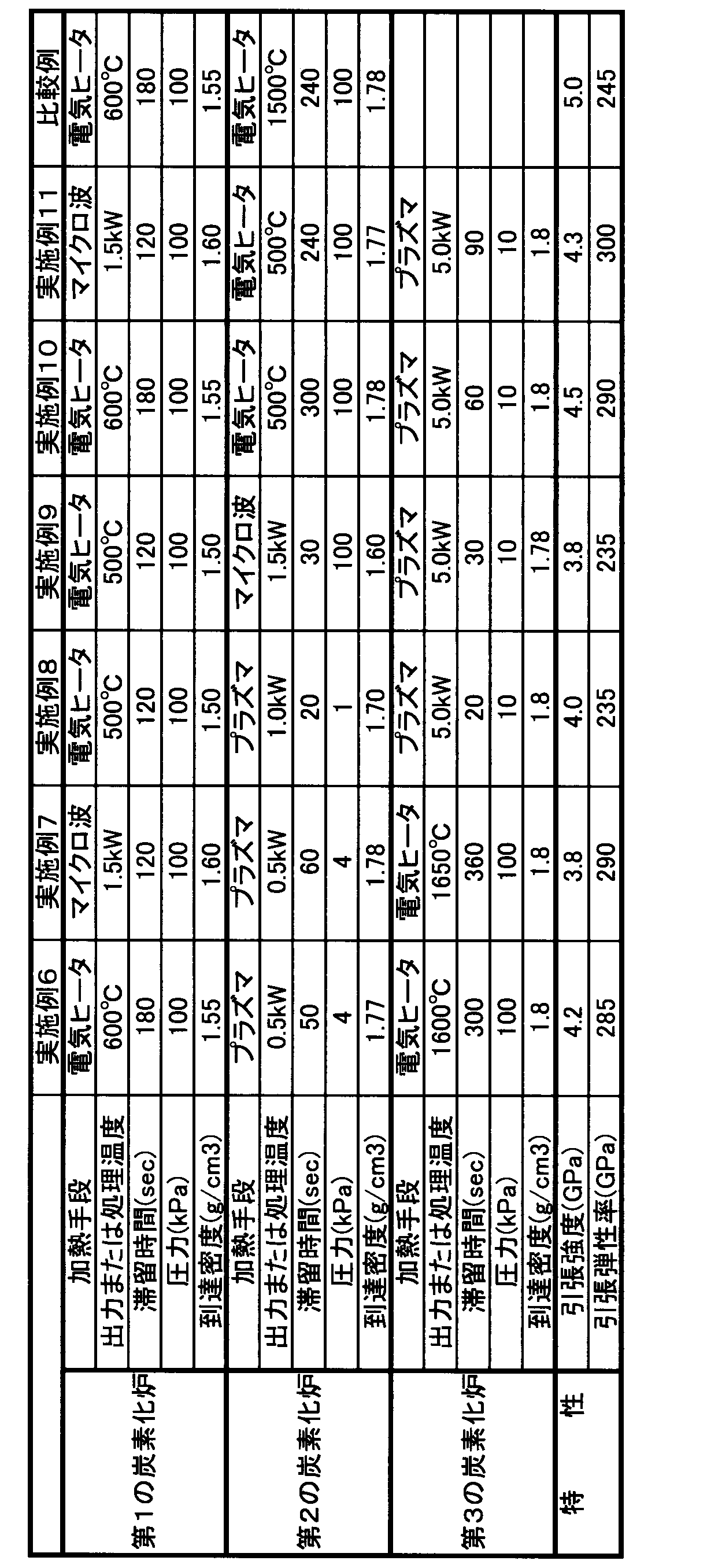
- Examples of carbonization methods and carbon fiber production methods according to Embodiments 1 to 11 are shown in Tables 1 and 2.
- the carbonization method and the carbon fiber production method in each embodiment are not limited to the numbers shown in each example in the table.
- corresponds to the number which shows embodiment. That is, “Example 1” in the table is an example of the first embodiment.
- examples using a conventional electric heater are listed in Tables 1 and 2 as comparative examples. In all Examples 1 to 11, the residence time in the furnace is shorter than that of the comparative example.
- nth carbonization furnace The carbonization furnace existing nth from the upstream side in the fiber running direction is referred to as “nth carbonization furnace”, and the carbonization process by the nth carbonization furnace is referred to as “nth carbonization process”.
- N is a natural number of 2 or more.
- first carbonization furnace there are two carbonization furnaces for heating the fiber, and the first carbonization furnace existing from the upstream side in the fiber traveling direction is referred to as a “first carbonization furnace”, and the second carbon is present.
- the conversion furnace is referred to as a “second carbonization furnace”. Heating using plasma is performed in the second carbonization furnace.
- the heating means of the first carbonization furnace is not particularly limited, but here microwaves are used.
- the precursor fiber that enters the first carbonization furnace is a flame-resistant fiber that has been flame-resistant.
- the flame resistant fiber here is, for example, a fiber having a density of 1.3 [g / cm 3 ] to [1.45 g / cm 3 ].
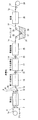
- FIG. 1 is a schematic view showing a production process of carbon fiber.
- Carbon fiber is manufactured using a precursor which is a precursor fiber.
- One precursor is a bundle of a plurality of, for example, 12,000 filaments. In some cases, it may be a precursor fiber bundle or a carbon fiber bundle.
- the precursor 1a is obtained by spinning a spinning solution obtained by polymerizing a monomer containing 90% by mass or more of acrylonitrile in a wet spinning method or a dry wet spinning method, and then washing, drying, and stretching.
- a monomer to be copolymerized alkyl acrylate, alkyl methacrylate, acrylic acid, acrylamide, itaconic acid, maleic acid, or the like is used.
- the speed for producing the precursor 1a is different from the speed for producing carbon fiber by carbonizing the precursor 1a. For this reason, the manufactured precursor 1a is once accommodated in a carton or wound around a bobbin.
- the precursor 1a is pulled out from, for example, a bobbin and travels downstream. On the way, various treatments are performed and the carbon fiber is wound around the bobbin 39.
- the carbon fiber has a flameproofing step for making the precursor 1 a flameproof, a carbonization step for carbonizing the stretched fiber (hereinafter referred to as “flameproof fiber”) 1 b, and A carbonized fiber (hereinafter also referred to as “fiber after carbonization”) 1d surface treatment step, a sizing step of attaching resin to the fiber 1e with improved surface, and a resin attached It is manufactured through a drying process for drying the fibers 1f.
- 1 g of the dried fiber is wound around the bobbin 39 as 1 g of carbon fiber.
- the fiber which finished each process is distinguished like the flame resistant fiber 1b, for example, "1" is used for the code
- the treatment for making the precursor 1a flame resistant is the flameproofing treatment
- the treatment for carbonizing the flame resistant fiber 1b is carbonized
- the treatment for improving the surface of the fiber 1d after carbonization is the surface treatment
- the fiber whose surface is improved The process of attaching the resin to 1e is referred to as a sizing process
- the process of drying the fiber 1f to which the resin is attached is referred to as a drying process.
- the flameproofing step is performed using the flameproofing furnace 3 in which the inside of the furnace is set to an oxidizing atmosphere of 200 [° C.] to 350 [° C.]. Specifically, the flame resistance is performed by passing the precursor 1a once or a plurality of times through the flame resistance furnace 3 in an air atmosphere.
- the oxidizing atmosphere may contain oxygen, nitrogen dioxide, or the like.
- the precursor 1a in the flameproofing process is stretched with a predetermined tension in accordance with the carbon fiber to be manufactured.
- the draw ratio in the flameproofing step is, for example, in the range of 0.7 to 1.3.
- the stretching of the precursor 1a is performed by a plurality of rollers. For example, the stretching is performed by the two rollers 5 and 7 at the entrance of the flameproofing furnace 3 and the three rollers 9, 11 and 13 at the exit.
- Carbonization process is a process of producing a thermal decomposition reaction by heating the flame resistant fiber 1b and performing carbonization. Carbonization is performed by the flame resistant fiber 1 b passing through the first carbonization furnace 15 and the fiber 1 c passing through the first carbonization furnace 15 passing through the second carbonization furnace 17. That is, carbonization is performed by passing through at least two carbonization furnaces 15 and 17.
- first carbonization the carbonization performed in the first carbonization furnace 15
- first carbonization treatment the first carbonization treatment is finished
- fiber 1c fiber after the first carbonization treatment
- the carbonization performed in the second carbonization furnace 17 is referred to as “second carbonization” or “second carbonization treatment”, and the second carbonization treatment is finished (second carbonization furnace).
- the fiber 1d (from 17) is referred to as “fiber after the second carbonization treatment” or “fiber after carbonization”.
- a plurality of carbonization furnaces are provided in an independent form.
- the first carbonization furnace 15 and the second carbonization furnace 17 are provided independently of each other, and an adjusting means for adjusting the tension of the fibers may be provided between the carbonization furnaces 15 and 17. it can.
- a roller 19 is provided outside the first carbonization furnace 15 at the inlet side, and a roller 21 is provided between the first carbonization furnace 15 and the second carbonization furnace 17, and the second carbonization furnace.
- a roller 23 is provided on the exit side outside 17. The carbonization step will be described in detail later.
- the surface treatment step is performed by passing the carbonized fiber 1d through the surface treatment apparatus 25.
- a roller 25 is provided outside the surface treatment apparatus 25 and on the outlet side.
- surface treatment when it is set as a composite material using 1g of carbon fibers, the affinity and adhesiveness of 1g of carbon fibers and matrix resin improve.
- the surface treatment is generally performed by oxidizing the surface of the carbon fiber 1d.
- As the surface treatment for example, there is a treatment in a liquid phase or a gas phase.
- the treatment in the liquid phase chemical oxidation by immersing the carbon fiber 1d in an oxidizing agent, anodic electrolytic oxidation by energizing in an electrolytic solution in which the carbon fiber 1d is immersed, and the like are industrially used.
- the treatment in the gas phase can be performed by passing the carbon fiber 1d through an oxidizing gas or spraying active species generated by discharge or the like.
- the sizing process is performed when the fiber 1 e passes through the resin liquid 29.
- the resin liquid 29 is stored in the resin bath 27.
- the convergence property of the surface-treated fiber 1e increases by a sizing process.
- the fiber 1e in the sizing process passes through the resin liquid 29 while changing the traveling direction by the plurality of rollers 31 and 33 disposed in the resin bath 27 and the periphery of the resin bath 27.
- the resin liquid 29 for example, a liquid or emulsion liquid in which an epoxy resin, a urethane resin, a phenol resin, a vinyl ester resin, an unsaturated polyester resin, or the like is dissolved in a solvent is used.
- Drying process The drying process is performed by passing the fiber 1 f through the drying furnace 35.
- the dried fiber 1g is wound around a bobbin 39 outside the drying furnace 35 and via a roller 37 on the downstream side (winding step).
- Carbonization in the carbon process is performed by a first carbonization process in which the flame resistant fiber 1b is rapidly and uniformly heated using a microwave in the first carbonization furnace 15 to undergo a thermal decomposition reaction, and heated by the microwave. And a second carbonization step in which carbonization is advanced by rapid and uniform heating using plasma while drawing the fibers 1c in the second carbonization furnace 17.
- rapid and uniform heating refers to heating such that the temperature rising rate is 500 [° C./min] or more and the temperature difference between the surface layer and the center of the fiber is 25 [° C.].
- a 1st carbonization process is thermally decomposed by heating, extends the flame resistant fiber 1b, forms the structure which arranges orientation and is easy to carbonize.
- energy that is converted into heat is applied to the flame resistant fiber 1b that travels in the first carbonization furnace 15 in an inert gas atmosphere so that heating is weakened on the way.
- an inert gas atmosphere For example, nitrogen or argon is used as the inert gas.
- the first carbonization furnace 15 has a heating means using microwaves, and has a configuration capable of changing the intensity of the microwaves received by the flame resistant fiber 1b.
- the first carbonization furnace 15 applies the first furnace body, the magnetron that is an oscillator that generates microwaves in the first furnace body, and the traveling region of the flame resistant fiber 1b in the first furnace body.
- An adjustment mechanism for adjusting the electric field strength of the microwave is an adjustment mechanism for adjusting the electric field strength of the microwave.
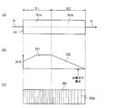
- FIG. 2 is a conceptual diagram showing the first carbonization furnace.
- FIG. 2A shows the first carbonization furnace
- FIG. 2B shows the intensity distribution of the microwaves irradiated to the flame resistant fiber passing through the first carbonization furnace
- FIG. 2C shows the first carbonization furnace. It is the schematic of the electric field strength adjustment mechanism in the carbonization furnace of (d), (d) shows the opening area by the slit of an electric field strength adjustment mechanism.
- the first carbonization furnace 15 has a first region 15a on the inlet side and a second region 15b on the outlet side along the traveling region of the flame resistant fiber 1b. is doing.
- the length in the traveling direction of the flame resistant fiber 1b in the first region 15a is “L1”
- the length in the traveling direction of the flame resistant fiber 1b in the second region 15b is “L2”.
- the region corresponding to the first region 15a in the electric field intensity adjusting mechanism 51 is also a “first region”, and the second region 15b of the first carbonization furnace 15 is The region corresponding to the second region 15b in the electric field intensity adjusting mechanism 51 is also referred to as a “second region”.
- the electric field intensity adjusting mechanism 51 is made of a material that blocks the transmission of microwaves, and has slits 51a that allow the passage of microwaves on its peripheral wall, as shown in FIG.
- the electric field strength of the microwave applied to the flame resistant fiber 1b is adjusted by the density (amount) of the slit 51a.
- the plurality of slits 51a in the first region 15a are provided at equal intervals in the traveling direction.
- the plurality of slits 51a in the second region 15b are provided in a state in which the interval becomes wider along the traveling direction toward the exit side, and the energy converted into heat increases or decreases by the strength of the electric field strength.
- the interval between the slits 51a in the second region 15b is wider than the interval between the slits 51a in the first region 15a.
- the amount of microwave irradiation to the flame resistant fiber 1b is larger in the first region 15a than in the second region 15b.
- the opening area by the slit 51a of the electric field intensity adjusting mechanism 51 is constant regardless of the traveling direction of the flame resistant fiber 1b in the first region 15a, and approaches the outlet in the second region 15b. It is decreasing according to.
- the microwave having the intensity distribution as shown in FIG. 2B is applied to the flame resistant fiber 1 b traveling in the first carbonization furnace 15 with the above configuration. Irradiate. That is, in the first carbonization step, the microwave S1 is applied at a constant intensity in the first region 15a located on the inlet side, and then the intensity gradually decreases in the second region 15b as it approaches the outlet. A microwave S2 is applied.
- the first region 15a is heated to receive energy that is converted into a constant heat in the first region 15a, and the flame resistant in the second region 15b.
- the boundary between the first region 15a and the second region 15b is defined by the degree of thermal decomposition of the flame resistant fiber 1b heated by the microwave.
- the first stage ends before the amount of cracked gas generated from the flame resistant fiber 1b due to thermal decomposition reaches a peak.
- Before peak here may be 10% or more and less than 100% with respect to the peak, and the closer to 100%, the higher the efficiency.
- the intensity of the microwave is gradually reduced in the second stage is to prevent the flame resistant fiber 1b from accumulating heat by heating the flame resistant fiber 1b and preventing the flame resistant fiber 1b from being cut by the accumulated heat.
- the first stage gives energy to be converted into heat necessary for the flame resistant fiber 1b to undergo a thermal decomposition reaction
- the second stage heats necessary for carbonization within a range in which the flame resistant fiber 1b is not cut by heat storage. Giving energy to be converted into.
- the cracked gas is, for example, an organic compound, ammonia (NH 3 ), or hydrogen cyanide (HCN) generated by the decomposition of polyacrylonitrile.
- the temperature of the flame resistant fiber 1b is 350 [° C.] to 500 [° C.], and the generated amount is the largest. Become more.
- the density of the flame resistant fiber 1b at the temperature at which the gas amount reaches a peak is approximately 1.5 [g / cm 3 ].
- the first stage can be said to be a process of irradiating the flame resistant fiber 1b with microwave until the density of the flame resistant fiber 1b becomes 1.40 [g / cm 3 ] to 1.50 [g / cm 3 ]. .
- the total amount of energy converted into heat given in the first carbonization step is an amount that does not cause rapid carbonization due to heating and heat generation.
- the amount of energy converted into heat is such an amount that carbonization proceeds slowly without generating heat after a large amount of cracked gas is generated by pyrolysis (this amount is expressed in multiple stages). Divided into two stages, for example).
- the amount of heat energy in the first carbonization process is such that the density of the flame resistant fiber 1b is 1.50 [g / cm 3 ] to 1.60 [g / cm 3]. ] In such a range. For this reason, the 1st carbonization process of the flame resistant fiber 1b can be performed stably.
- the microwave irradiation time in the first stage is such that the energy converted into the necessary heat is obtained by conducting experiments in advance on the peak of the generation amount of cracked gas, the density and temperature of the flame resistant fiber 1b, and the intensity of the microwave. It is obtained in relation to.
- the tension of the flame resistant fiber 1b in the first carbonization step is set in a range where the heated flame resistant fiber 1b is not cut.
- the flame-resistant fiber 1b in a heated state is easily cut because it has undergone a structural change, and a range of tension that does not cut can be obtained by conducting experiments in advance.
- the tension of the flame resistant fiber 1b varies depending on the rate of thermal decomposition, the range in which thermal decomposition occurs, etc., but the draw ratio is preferably in the range of 0.9 to 1.1.
- the second carbonization step is performed in the second carbonization furnace 17 with respect to the fiber 1c after the first carbonization treatment that has passed through the first carbonization furnace 15.
- rapid and uniform heating is performed under a tension different from the tension in the first carbonization furnace 15.
- nitrogen or argon is used as the inert gas.
- the tension different from the tension in the first carbonization furnace 17 is, for example, a tension higher than the tension in the first carbonization furnace 17.
- the tension in the second carbonization step is 1.0 to 5.0 times the tension in the first carbonization step.
- the second carbonization step carbonization of the fiber 1c after the first carbonization treatment is further advanced. Therefore, the second carbonization step is performed on the fibers 1c after the first carbonization treatment until the density of the fibers becomes 1.70 [g / cm 3 ] to 1.90 [g / cm 3 ]. It can also be said to be a process of rapid and uniform heating.
- Plasma is used as an example of heating means.
- the heating means repeatedly generates arc discharge between a pair of electrodes arranged in a state where the traveling region of the fiber 1c after the first carbonization treatment is sandwiched from, for example, the vertical direction. Plasma is generated in the second carbonization furnace 17 and heated.
- the fiber 1c after the first carbonization treatment is heated by passing through the plasma.
- the concentration of the plasma generated so that the structure of the fiber 1d after the second carbonization treatment is equivalent to the physical properties of the fiber treated by existing atmospheric heating (for example, heating by an electric heater).
- existing atmospheric heating for example, heating by an electric heater.
- the existing atmosphere heating is heating in a temperature range corresponding to 900 [° C.] to 2500 [° C.].
- the flame resistant fiber 1b is stretched with a tension suitable for the state of the flame resistant fiber 1b (including the fiber 1c after the first carbonization treatment) in the carbonization step in order to adjust the orientation of the condensed aromatic ring.
- the first carbonization furnace 15 and the second carbonization furnace 17 exist separately and independently, so that the fibers 1b in the carbonization furnaces 15 and 17 are present.
- 1c can be applied to the fibers 1b, 1c.
- a nip roller 21 is disposed between the first carbonization furnace 15 and the second carbonization furnace 17 so as to sandwich the fiber 1c after the first carbonization treatment with a pair of upper and lower rollers.
- the microwave used in the first carbonization furnace 15 has a wavelength in the range of 0.705 [m] to 0.00737 [m] and a frequency of 425 [MHz] to Each is within a range of 40680 [MHz], and for example, a magnetron type oscillation device is used.
- the length L1 shown in FIG. 2B is in the range of 0.1 [m] to 10 [m]
- the length L2 is in the range of 0.2 [m] to 10 [m].
- the output of the microwave is in the range of 0.1 [kW] to 1000 [kW].
- the running speed of the flame resistant fiber 1b is in the range of 0.1 [m / min] to 50 [m / min].
- the tension acting on the flame resistant fiber 1b is in the range of 0.1 [mN / dtex] to 5 [mN / dtex].
- the inside of the first carbonization furnace 15 is maintained at 91000 [Pa] to 122000 [Pa] in a nitrogen atmosphere.
- the flame resistant fiber 1b is carbonized until the density becomes, for example, 1.50 [g / cm 3 ] to 1.60 [g / cm 3 ].
- the plasma used in the second carbonization furnace 17 is, for example, microwave plasma.
- a microwave is generated in the second carbonization furnace 17 by a magnetron type oscillation device to excite nitrogen in the furnace, thereby filling the furnace with plasma.
- the inside of the second carbonization furnace 17 is maintained at 100 [Pa] to 122000 [Pa] in a nitrogen atmosphere.
- the speed of the fiber 1c after the first carbonization treatment is in the range of 0.08 [m / min] to 55 [m / min].
- the tension acting on the fiber 1c after the first carbonization treatment is in the range of 0.2 [mN / dtex] to 5 [mN / dtex].
- the output of the microwave when generating plasma is in the range of 0.1 [kW] to 1000 [kW].
- Embodiment 2 demonstrates the example which irradiates plasma to the fiber 1c after a 1st carbonization process in a 2nd carbonization process.
- the carbon fiber manufacturing method according to Embodiment 2 includes a flameproofing process, a carbonization process, a surface treatment process, a sizing process, and a drying process.
- the flameproofing process, the first carbonization process of the carbonization process, the surface treatment process, the sizing process, and the drying process in the second embodiment are the same as those described in the first embodiment. For this reason, the 2nd carbonization process of the carbonization process which concerns on Embodiment 2 is demonstrated here.
- the carbonization process according to Embodiment 2 includes a twisting process in which the first and second carbonized fibers 1c that have passed through the first carbonization furnace 15 are twisted so that the front and back are mutually reversed. That is, the carbonization process includes a twisting process between the first carbonization process and the second carbonization process.
- the reason for performing a twisting process is mentioned later, it is for reducing the dispersion
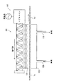
- FIG. 3 is a schematic diagram of a second carbonization furnace according to the second embodiment.
- the second carbonization furnace 101 includes a furnace main body 103 through which the fiber 1c after the first carbonization treatment passes, a plasma irradiation apparatus 107 that irradiates plasma 105 from the upper part of the furnace main body 103, and a furnace main body 103.
- a furnace main body 103 through which the fiber 1c after the first carbonization treatment passes, a plasma irradiation apparatus 107 that irradiates plasma 105 from the upper part of the furnace main body 103, and a furnace main body 103.
- an introduction pipe 109 and an exhaust pipe 111 for making the inside of the atmosphere an inert atmosphere.
- nitrogen is used as the inert gas.
- the plasma irradiation device 107 generates surface wave plasma using a slot antenna system. For this reason, plasma is irradiated only on the upper surface of the fiber 1c after the first carbonization treatment passing through the second carbonization furnace 101.
- the inventor considers a double-sided irradiation technique in which plasma irradiation devices 107 are provided above and below the furnace body 103, and the first carbonized fiber 1c in the second carbonization furnace is irradiated with plasma from the front and back. is doing.
- the plasma irradiation device 107 is arranged on one of the upper and lower sides of the furnace body 103, in the example here, on the upper side, and after the first carbonization treatment in the second carbonization furnace 101.
- a single-sided irradiation technique for irradiating the upper surface of the fiber 1c with plasma is also being studied.
- the filament is a fiber bundle in which a plurality of filaments are bundled.
- the variation in the filament length is caused by the temperature of the filament running in the position near the upper surface of the fiber bundle in the fiber (bundle) 1c after the first carbonization treatment running in the second carbonization furnace 101.
- the temperature is higher than the temperature of the filament running near the lower surface of the fiber bundle, and it is assumed that the carbonization degree differs between the upper part and the lower part of the fiber (bundle) 1c after the first carbonization treatment. ing.
- the carbonization process according to Embodiment 2 includes a twisting process as described above. Therefore, the fiber 1c after the first carbonization treatment running in the second carbonization furnace 101 is turned upside down. Thereby, the temperature difference between the upper surface and the lower surface of the fiber 1c after the first carbonization treatment in the second carbonization furnace 101 can be reduced, and the thermal shrinkage variation between the filaments can be reduced.
- the number of twists may be the same as long as the number of times of plasma irradiation is reversed between the front and back while the fiber 1c after the first carbonization treatment passes through the second carbonization furnace 101. That is, the number of times (time) that the upper surface is irradiated with plasma may be the same as the number of times (time) that the lower surface is irradiated with plasma.
- the number of inversions is 10 [times / m] or more, that is, the number of twists Is preferably 5 [times / m] or more.
- the number of twists referred to here is the number of rotations of the fiber bundle per 1 [m].
- twisting device for example, a false twisting machine can be used.
- Embodiment 3 is a mode in which there are two carbonization furnaces and the fibers are heated by using plasma in the two carbonization furnaces.
- the fiber may travel in the plasma atmosphere as in the first embodiment, or the traveling fiber may be irradiated with plasma as in the second embodiment. Also good.
- the inside of the first carbonization furnace is kept at 1 [kPa] in a nitrogen atmosphere.
- the output when generating plasma is 1.0 [kW].
- the residence time in the furnace is 15 [sec], and the flame resistant fiber can be carbonized until the density reaches 1.55 [g / cm 3 ].
- plasma in the first carbonization furnace when using plasma in the first carbonization furnace, for example, it can be implemented by adjusting the energy converted into the heat of plasma in the second carbonization furnace 17 of the first embodiment. More specifically, it can be used by adjusting (thinning) the concentration of plasma generated in the second carbonization furnace 17.
- the inside of the second carbonization furnace is kept at 8 [kPa] in a nitrogen atmosphere.
- the output when generating plasma is 3.0 [kW].
- the residence time in the furnace is 30 [sec], and carbonization is possible until the density reaches 1.80 [g / cm 3 ].
- the obtained carbon fiber had a tensile strength of 3.5 [GPa] and a tensile elastic modulus of 235 [GPa].
- the fourth embodiment there are two carbonization furnaces, the first carbonization furnace uses plasma, and the second carbonization furnace uses an electric heater to heat the fibers.
- the inside of the first carbonization furnace is kept at 1 [kPa] in a nitrogen atmosphere.
- the output when generating plasma is 1.5 [kW].
- the residence time in the furnace is 30 [sec], and the flame resistant fiber can be carbonized until the density reaches 1.76 [g / cm 3 ].
- the inside of the second carbonization furnace is maintained at 100 [kPa] in a nitrogen atmosphere.
- the temperature in the furnace is set to 1400 [° C.] by an electric heater. Carbonization is possible until the residence time in the furnace is 240 [sec] and the density is 1.79 [g / cm 3 ].
- the obtained carbon fiber had a tensile strength of 5.0 [GPa] and a tensile modulus of 240 [GPa].
- Embodiment 5 is a form in which there are two carbonization furnaces, the first carbonization furnace uses an electric heater, and the second carbonization furnace uses plasma to heat the fibers.
- the inside of the first carbonization furnace is maintained at 100 [kPa] in a nitrogen atmosphere.
- the temperature in the furnace is set to 600 [° C.] by an electric heater. Carbonization is possible until the residence time in the furnace is 180 [sec] and the density is 1.55 [g / cm 3 ].
- the inside of the second carbonization furnace is kept at 4 [kPa] in a nitrogen atmosphere.
- the output when generating plasma is 0.5 [kW]. Carbonization is possible until the residence time in the furnace is 50 [sec] and the density is 1.77 [g / cm 3 ].
- the obtained carbon fiber had a tensile strength of 4.0 [GPa] and a tensile modulus of 240 [GPa].
- Embodiment 6 there are three carbonization furnaces, the first carbonization furnace uses an electric heater, the second carbonization furnace uses plasma, and the third carbonization furnace uses an electric heater. Thus, the fiber is heated.
- the inside of the first carbonization furnace is maintained at 100 [kPa] in a nitrogen atmosphere.
- the temperature in the furnace is set to 600 [° C.] by an electric heater. Carbonization is possible until the residence time in the furnace is 180 [sec] and the density is 1.55 [g / cm 3 ].
- the inside of the second carbonization furnace is kept at 4 [kPa] in a nitrogen atmosphere.
- the output when generating plasma is 0.5 [kW]. Carbonization is possible until the residence time in the furnace is 50 [sec] and the density is 1.77 [g / cm 3 ].
- the inside of the third carbonization furnace is kept at 100 [kPa] in a nitrogen atmosphere.
- the temperature in the furnace is set to 1600 [° C.] by an electric heater. Carbonization is possible until the residence time in the furnace is 300 [sec] and the density is 1.80 [g / cm 3 ].
- the obtained carbon fiber had a tensile strength of 4.2 [GPa] and a tensile elastic modulus of 285 [GPa].
- the first carbonization furnace uses microwaves
- the second carbonization furnace uses plasma
- the third carbonization furnace uses an electric heater.
- the fiber is heated.
- the inside of the first carbonization furnace is maintained at 100 [kPa] in a nitrogen atmosphere.
- the output of the microwave is 1.5 [kW]. Carbonization is possible until the residence time in the furnace is 120 [sec] and the density is 1.60 [g / cm 3 ].
- the inside of the second carbonization furnace is kept at 4 [kPa] in a nitrogen atmosphere.
- the output when generating plasma is 0.5 [kW]. Carbonization is possible until the residence time in the furnace is 60 [sec] and the density is 1.78 [g / cm 3 ].
- the inside of the third carbonization furnace is maintained at 100 [kPa] in a nitrogen atmosphere.
- the temperature in the furnace is set to 1650 [° C.] by an electric heater. Carbonization is possible until the residence time in the furnace is 360 [sec] and the density is 1.80 [g / cm 3 ].
- the obtained carbon fiber had a tensile strength of 3.8 [GPa] and a tensile elastic modulus of 290 [GPa].
- the first carbonization furnace uses an electric heater
- the second carbonization furnace uses plasma
- the third carbonization furnace uses plasma. It is a form which heats a fiber.
- the inside of the first carbonization furnace is maintained at 100 [kPa] in a nitrogen atmosphere.
- the temperature in the furnace is set to 500 [° C.] by an electric heater. Carbonization is possible until the residence time in the furnace is 120 [sec] and the density is 1.50 [g / cm 3 ].
- the inside of the second carbonization furnace is kept at 1 [kPa] in a nitrogen atmosphere.
- the output when generating plasma is 1.0 [kW]. Carbonization is possible until the residence time in the furnace is 20 [sec] and the density is 1.70 [g / cm 3 ].
- the inside of the third carbonization furnace is kept at 10 [kPa] in a nitrogen atmosphere.
- the output when generating plasma is 5.0 [kW]. Carbonization is possible until the residence time in the furnace is 20 [sec] and the density is 1.80 [g / cm 3 ].
- the obtained carbon fiber had a tensile strength of 4.0 [GPa] and a tensile modulus of 235 [GPa].
- the first carbonization furnace uses an electric heater
- the second carbonization furnace uses microwaves
- the third carbonization furnace uses plasma.
- the fiber is heated.
- the inside of the first carbonization furnace is maintained at 100 [kPa] in a nitrogen atmosphere.
- the temperature in the furnace is set to 500 [° C.] by an electric heater. Carbonization is possible until the residence time in the furnace is 120 [sec] and the density is 1.50 [g / cm 3 ].
- the inside of the second carbonization furnace is maintained at 100 [kPa] in a nitrogen atmosphere.
- the output when generating the microwave is 1.5 [kW]. Carbonization is possible until the residence time in the furnace is 30 [sec] and the density is 1.60 [g / cm 3 ].
- the inside of the third carbonization furnace is kept at 10 [kPa] in a nitrogen atmosphere.
- the output when generating plasma is 5.0 [kW]. Carbonization is possible until the residence time in the furnace is 30 [sec] and the density is 1.78 [g / cm 3 ].
- the obtained carbon fiber had a tensile strength of 3.8 [GPa] and a tensile modulus of 235 [GPa].
- the first carbonization furnace uses an electric heater
- the second carbonization furnace uses an electric heater
- the third carbonization furnace uses plasma.
- the fiber is heated.
- the inside of the first carbonization furnace is maintained at 100 [kPa] in a nitrogen atmosphere.
- the temperature in the furnace is set to 600 [° C.] by an electric heater. Carbonization is possible until the residence time in the furnace is 180 [sec] and the density is 1.55 [g / cm 3 ].
- the inside of the second carbonization furnace is maintained at 100 [kPa] in a nitrogen atmosphere.
- the temperature in the furnace is set to 500 [° C.] by an electric heater. Carbonization is possible until the residence time in the furnace is 300 [sec] and the density is 1.78 [g / cm 3 ].
- the inside of the third carbonization furnace is kept at 10 [kPa] in a nitrogen atmosphere.
- the output when generating plasma is 5.0 [kW]. Carbonization is possible until the residence time in the furnace is 60 [sec] and the density is 1.80 [g / cm 3 ].
- the obtained carbon fiber had a tensile strength of 4.5 [GPa] and a tensile modulus of 290 [GPa].
- the first carbonization furnace uses microwaves
- the second carbonization furnace uses electric heaters
- the third carbonization furnace uses plasma.
- the fiber is heated.
- the inside of the first carbonization furnace is maintained at 100 [kPa] in a nitrogen atmosphere.
- the output of the microwave is 1.5 [kW]. Carbonization is possible until the residence time in the furnace is 120 [sec] and the density is 1.60 [g / cm 3 ].
- the inside of the second carbonization furnace is maintained at 100 [kPa] in a nitrogen atmosphere.
- the temperature in the furnace is set to 500 [° C.] by an electric heater. Carbonization is possible until the residence time in the furnace is 240 [sec] and the density is 1.77 [g / cm 3 ].
- the inside of the third carbonization furnace is kept at 10 [kPa] in a nitrogen atmosphere.
- the output when generating plasma is 5.0 [kW]. Carbonization is possible until the residence time in the furnace is 90 [sec] and the density is 1.80 [g / cm 3 ].
- the obtained carbon fiber had a tensile strength of 4.3 [GPa] and a tensile modulus of 300 [GPa].
- Carbon Fiber In the embodiment, a method for producing a carbon fiber having 12,000 filaments has been described. However, other numbers of precursor fibers, such as 3,000, 6,000, and 24,000 filaments, have been described. It can also be applied to carbonization of carbon and a method for producing carbon fiber.
- the carbon fiber manufacturing method including the carbonization step has been described.
- the graphitization treatment may be performed before the surface treatment step. That is, in the embodiment, the method for producing carbon fiber having a general-purpose product (elastic modulus 240 [GPa]) has been mainly described. It can also be used for carbonization of precursor fibers for use in production, and of course, it can also be used for the production of high-performance carbon fibers.
- GPa elastic modulus 240
- a metal electric field strength adjusting mechanism 51 is disposed in a region through which the flame resistant fiber 1b passes in the first carbonization furnace 15, and the electric field strength adjusting mechanism.
- the slit 51a which can pass a microwave is provided in 51, and the intensity
- the microwave intensity may be adjusted by other methods.
- an example in which the inside of the first carbonization furnace is divided into a plurality of regions along the traveling direction of the flame resistant fibers and the intensity of the microwave is changed in each region will be described as a first modification.
- FIG. 4 is a view for explaining a first carbonization furnace according to the first modification.
- the first carbonization furnace 201 has a first region 201a existing between an entrance and a position moved from the entrance to the exit side by a distance 1L1, and a position moved from the entrance by a distance 1L1. And the second region 201b existing between the position and the exit moved by the distance 1L2.
- a magnetron that is a microwave oscillator is provided in the first region 201a.
- the output of the microwave 1S1 in the first region 201a is kept constant.
- the second area 201b is further divided into a plurality of small areas. Here, it is divided into three small areas.
- the three small regions are a first small region 201ba, a second small region 201bb, and a third small region 201bc in this order from the first region 201a side along the traveling direction of the flame resistant fiber 1b.
- the distance (length) in the traveling direction of each of the small areas 201ba, 201bb, and 201bc is 1L21, 1L22, and 1L23 as shown in FIG.
- 1L21, 1L22, 1L23 have the same length.
- Each of the small areas 201ba, 201bb, and 201bc is provided with a magnetron, which is a microwave oscillator, so that each small area 201ba, 201bb, and 201bc can output a microwave independent of the other small areas. It is like that.
- the output of the microwave 1S2 of each small region 201ba, 201bb, 201bc is gradually reduced as it approaches the exit, as shown in FIG. 4 (b). Note that the output of the microwave 1S2 in each of the small areas 201ba, 201bb, and 201bc is smaller than the output of the microwave 1S1 in the first area 201a.
- the intensity of the microwave S1 applied to the flame resistant fiber 1b in the first carbonization step in the carbonization step is set to the first. It is constant in the region 15a.
- the intensity of the microwave applied in the first region of the first carbonization process may not be constant, and an example in which the intensity of the microwave is changed will be described below as a second modification.
- FIG. 5 is a conceptual diagram showing a heating state in the first carbonization step according to Modification 2.
- FIG. 5A shows the first carbonization furnace
- FIG. 5B shows the intensity distribution of microwaves irradiated to the flame resistant fiber passing through the first carbonization furnace
- FIG. 5C shows the first carbonization furnace. It is the schematic of the electric field strength adjustment mechanism in the carbonization furnace.
- the strength of the microwave irradiated to the flame resistant fiber 1b is increased as the distance from the entrance of the first carbonization furnace in the traveling direction of the flame resistant fiber 1b is increased.
- the microwave is irradiated with an intensity distribution that decreases the intensity as it approaches the outlet of the first carbonization furnace.
- an intensity distribution that decreases the intensity as it approaches the outlet of the first carbonization furnace.
- the basic structure of the first carbonization furnace 251 is the same as that of the first carbonization furnace 15 according to the first embodiment. That is, the first carbonization furnace 251 includes a first furnace main body, a magnetron, and an electric field intensity adjustment mechanism 253 in which a plurality of slits 253a are formed. Note that the first carbonization furnace 251 that adjusts the intensity of the microwave applied to the flame resistant fiber 1b by the density of the slit 253a includes the first region 251a and the first region 251a as shown in FIG. 2 regions 251b.
- the length in the running direction of the flame resistant fiber 1b in the first region 251a is “2L1”
- the length in the running direction of the flame resistant fiber 1b in the second region 251b is “2L2”.
- the plurality of slits 253a corresponding to the first region 251a are in a region from approximately half to the boundary of the second region 251b in a state where the interval decreases in the region from the entrance to approximately half of the traveling direction as the distance from the entrance increases. Each is provided in a state of being equally spaced.
- the plurality of slits 253a corresponding to the second region 251b are provided in a state in which the interval becomes wider as approaching the outlet side along the traveling direction of the flame resistant fiber 1b.
- the flame resistant fiber 1b running inside the first carbonization furnace 251 has a strength distribution in which the strength changes in the first region 251a as shown in FIG. 5B.
- Microwave 2S1 can be irradiated.
- Heating by plasma (1) Heating means In the first embodiment, plasma is generated using arc discharge, and in the second embodiment, plasma is generated using surface waves. However, plasma may be generated using other methods. As another method, there is a method of inductively heating a gas using a high frequency electromagnetic field. (2) Types of Plasma In Embodiments 1 to 11, plasma is generated in a nitrogen atmosphere, but plasma may be generated using another inert gas.
Landscapes
- Chemical & Material Sciences (AREA)
- Engineering & Computer Science (AREA)
- Organic Chemistry (AREA)
- Chemical Kinetics & Catalysis (AREA)
- General Chemical & Material Sciences (AREA)
- Textile Engineering (AREA)
- Inorganic Chemistry (AREA)
- Manufacturing & Machinery (AREA)
- Life Sciences & Earth Sciences (AREA)
- General Life Sciences & Earth Sciences (AREA)
- Geology (AREA)
- Inorganic Fibers (AREA)
Abstract
Description
本発明の一態様に係る炭素化工程は、走行中の前駆体繊維を炭素化する炭素化方法において、繊維を加熱する炭素化炉が走行方向に複数個存在し、複数個の炭素化炉のうち、少なくとも1個の炭素化炉において、プラズマを利用して炉内を通過する繊維を加熱する。
炭素化方法及び当該炭素化方法を利用した炭素繊維の製造方法について、前駆体繊維がアクリロニトリル系繊維である場合を例にとって以下説明する。
実施形態1では、繊維を加熱する炭素化炉が2個あり、繊維の走行方向の上流側から1番目に存在する炭素化炉を「第1の炭素化炉」とし、2番目に存在する炭素化炉を「第2の炭素化炉」としている。プラズマを利用した加熱は、第2の炭素化炉で行われる。
図1は、炭素繊維の製造工程を示す概略図である。
耐炎化工程は、炉内が200[℃]~350[℃]の酸化性雰囲気に設定された耐炎化炉3を利用して行う。具体的には、耐炎化は、空気雰囲気中の耐炎化炉3内をプリカーサ1aが1回又は複数回通過することで行われる。なお、酸化性雰囲気は、酸素、二酸化窒素等を含んでいてもよい。
炭素化工程は、耐炎繊維1bを加熱することで熱分解反応を生じさせて炭素化を行う工程である。炭素化は、耐炎繊維1bが第1の炭素化炉15を通過し、さらに、第1の炭素化炉15を通過した繊維1cが第2の炭素化炉17を通過することで行われる。つまり、炭素化は、少なくとも2個の炭素化炉15,17を通過することで行われる。
表面処理工程は、炭素化後の繊維1dが表面処理装置25内を通過することで行われる。表面処理装置25の外であって出口側にはローラ25が設けられている。なお、表面処理することで、炭素繊維1gを利用して複合材料とした場合、炭素繊維1gとマトリックス樹脂との親和性や接着性が向上する。
サイジング工程は、繊維1eが樹脂液29内を通過することで行われる。樹脂液29は、樹脂浴27に貯留されている。なお、サイジング工程により、表面処理された繊維1eの収束性が高まる。
乾燥工程は、繊維1fが乾燥炉35内を通過することで行われる。なお、乾燥した繊維1gは、乾燥炉35の外であって下流側のローラ37を介してボビン39に巻き取られる(巻取工程である。)。
炭素工程における炭素化は、耐炎繊維1bを第1の炭素化炉15内でマイクロ波を利用して急速均一加熱して熱分解反応させる第1の炭素化工程と、マイクロ波で加熱した繊維1cを第2の炭素化炉17内で延伸しながらプラズマを利用して急速均一加熱して炭素化を進行させる第2の炭素化工程とを含んでいる。
第1の炭素化工程は、加熱することで熱分解し、耐炎繊維1bを延伸させて、配向を整えて炭素化し易い構造を形成する。
第2の炭素化工程は、第1の炭素化炉15を通過した第1の炭素化処理後の繊維1cに対して、第2の炭素化炉17内において、不活性ガス雰囲気中で、第1の炭素化炉15内での張力とは異なる張力下で、急速均一加熱する。なお、不活性ガスは、例えば、窒素、アルゴン等が利用される。また、第1の炭素化炉17内での張力とは異なる張力は、例えば、第1の炭素化炉17内の張力よりも高い張力である。具体的には、第2の炭素化工程での張力は、第1の炭素化工程の張力の1.0倍~5.0倍である。
第1の炭素化炉15で利用するマイクロ波は、波長が0.705[m]~0.00737[m]の範囲内に、周波数が425[MHz]~40680[MHz]の範囲内にそれぞれあり、例えば、マグネトロンタイプの発振装置を利用している。
第2の炭素化炉17で利用するプラズマは、例えば、マイクロ波プラズマである。マグネトロンタイプの発振装置によって第2の炭素化炉17内でマイクロ波を発生させ、炉内の窒素を励起させることで、炉内にプラズマを充満させている。
以下、実施形態2の一実施例について説明する。
実施形態1では、第2の炭素化工程において第1の炭素化処理後の繊維1cをプラズマ雰囲気中を通過させている。実施形態2では、第2の炭素化工程において第1の炭素化処理後の繊維1cにプラズマを照射する例を説明する。
以下、実施形態3の一実施例について説明する。
以下、実施形態4の一実施例について説明する。
実施形態4は、炭素化炉が2個あり、第1の炭素化炉はプラズマを利用し、第2の炭素化炉は電気ヒータを利用して、繊維を加熱する形態である。
以下、実施形態5の一実施例について説明する。
以下、実施形態6の一実施例について説明する。
以下、実施形態7の一実施例について説明する。
以下、実施形態8の一実施例について説明する。
以下、実施形態9の一実施例について説明する。
以下、実施形態10の一実施例について説明する。
以下、実施形態11の一実施例について説明する。

以上、実施形態1~11に基づいて説明したが、本発明は実施形態1~11に限られない。例えば、以下で説明する変形例と実施形態1~11のいずれかを適宜組み合わせてもよいし、複数の変形例を適宜組み合わせてもよい。
実施形態では、フィラメント数が12,000本の炭素繊維の製造方法について説明したが、フィラメント数が3,000本、6,000本、24,000本等の他の本数の前駆体繊維の炭素化及び炭素繊維の製造方法にも適用できる。
(1)マイクロ波の強度
実施形態1では、第1の炭素化炉15内における耐炎繊維1bが通過する領域に金属製の電界強度調整機構51を配置し、当該電界強度調整機構51にマイクロ波が通過できるスリット51aを設け、スリット51aの数(密度)で、マイクロ波の強度を調整している。
実施形態1では、図2の(b)に示すように、炭素化工程中の第1の炭素化工程において耐炎繊維1bに印加するマイクロ波S1の強度を第1領域15aで一定としている。
第1の炭素化炉251は、図5の(a)に示すように、第1領域251aと第2領域251bとを有している。第1領域251aの耐炎繊維の1bの走行方向の長さは「2L1」であり、第2領域251bの耐炎繊維1bの走行方向の長さは「2L2」である。
(1)加熱手段
実施形態1ではアーク放電を利用してプラズマを発生させ、実施形態2では表面波を利用してプラズマを発生させている。しかしながら、他の方法を利用してプラズマを発生してもよい。他の方法としては、高周波電磁場を利用して誘導的に気体を加熱する方法等がある。
(2)プラズマの種類
実施形態1~11では、窒素雰囲気中で、プラズマを発生させているが、他の不活性ガスを利用してプラズマを発生させてもよい。
1a プリカーサ
1b 耐炎繊維
1c 第1の炭素化処理後の繊維
15 第1の炭素化炉
15a 第1領域
15b 第2領域
17 第2の炭素化炉
21 ローラ
23 ローラ
51 電界強度調整機構
51a スペーサ
Claims (10)
- 走行中の前駆体繊維を炭素化する炭素化方法において、
繊維を加熱する炭素化炉が走行方向に複数個存在し、
複数個の炭素化炉のうち、少なくとも1個の炭素化炉において、プラズマを利用して炉内を通過する繊維を加熱する
ことを特徴とする炭素化方法。
- 前記少なくとも1個の炭素化炉では、プラズマを発生させて、発生したプラズマ中に繊維を通すことで、加熱する
請求項1に記載の炭素化方法。
- 前記少なくとも1個の炭素化炉では、プラズマを発生させて、発生したプラズマを繊維に照射することで、加熱する
請求項1に記載の炭素化方法。
- 前記少なくとも1個の炭素化炉は、繊維の走行方向の上流側から2番目以降に存在する炭素化炉である
請求項1~3の何れか1項に記載の炭素化方法。
- 繊維の走行方向の上流側から1番目に存在する炭素化炉は、マイクロ波及びプラズマの少なくとも一方を利用して、繊維を加熱する
請求項4に記載の炭素化方法。
- 前記1番目に存在する炭素化炉では、繊維が一定又は増加する熱に転換されるエネルギを受けるように加熱する第1段階と、前記第1段階の後に繊維が前記第1段階終了時に受けていた熱に転換されるエネルギよりも弱い熱に転換されるエネルギを受けるように加熱する第2段階とがあり、
前記第1段階は、加熱により繊維から発生するガス量がピークとなる前に、終了する
請求項5に記載の炭素化方法。
- 前記第2段階では、前記繊維の反応が緩やかに進行するように、前記繊維の受ける熱に転換されるエネルギを徐々に弱めて加熱する
請求項6に記載の炭素化方法。
- 前記第1段階を終了した繊維の密度が1.60g/cm3以下である
請求項6又は7に記載の炭素化方法。
- 前記1番目の炭素化炉を通過した繊維の密度が1.50g/cm3以上である
請求項5~8の何れか1項に記載の炭素化方法。
- 走行中の前駆体繊維を炭素化する炭素化工程を含む炭素繊維の製造方法において、
前記炭素化工程は、請求項1~9の何れか1項に記載の炭素化方法により行われる
ことを特徴とする炭素繊維の製造方法。
Priority Applications (4)
| Application Number | Priority Date | Filing Date | Title |
|---|---|---|---|
| US14/897,924 US9745671B2 (en) | 2013-07-26 | 2014-07-24 | Carbonization method and carbon fiber production method |
| JP2015528329A JP6063045B2 (ja) | 2013-07-26 | 2014-07-24 | 炭素化方法及び炭素繊維の製造方法 |
| CN201480031536.8A CN105264129B (zh) | 2013-07-26 | 2014-07-24 | 碳化方法及碳纤维的制造方法 |
| EP14829940.7A EP3026150B1 (en) | 2013-07-26 | 2014-07-24 | Carbonization method and carbon fiber production method |
Applications Claiming Priority (2)
| Application Number | Priority Date | Filing Date | Title |
|---|---|---|---|
| JP2013155364 | 2013-07-26 | ||
| JP2013-155364 | 2013-07-26 |
Publications (1)
| Publication Number | Publication Date |
|---|---|
| WO2015012349A1 true WO2015012349A1 (ja) | 2015-01-29 |
Family
ID=52393383
Family Applications (1)
| Application Number | Title | Priority Date | Filing Date |
|---|---|---|---|
| PCT/JP2014/069552 Ceased WO2015012349A1 (ja) | 2013-07-26 | 2014-07-24 | 炭素化方法及び炭素繊維の製造方法 |
Country Status (6)
| Country | Link |
|---|---|
| US (1) | US9745671B2 (ja) |
| EP (1) | EP3026150B1 (ja) |
| JP (1) | JP6063045B2 (ja) |
| CN (1) | CN105264129B (ja) |
| HU (1) | HUE041716T2 (ja) |
| WO (1) | WO2015012349A1 (ja) |
Cited By (6)
| Publication number | Priority date | Publication date | Assignee | Title |
|---|---|---|---|---|
| CN105696113A (zh) * | 2015-12-04 | 2016-06-22 | 江西大有科技有限公司 | 一种利用非平衡等离子体制造碳纤维的装置及其方法 |
| WO2016158955A1 (ja) * | 2015-03-31 | 2016-10-06 | 東邦テナックス株式会社 | 炭素繊維及び炭素繊維の製造方法 |
| WO2017076964A1 (de) * | 2015-11-05 | 2017-05-11 | Fraunhofer-Gesellschaft zur Förderung der angewandten Forschung e.V. | Anlage zur herstellung von kohlenstofffasern |
| KR20180071184A (ko) * | 2016-12-19 | 2018-06-27 | 주식회사 엘지화학 | 마이크로웨이브파를 이용한 탄소 섬유 제조 장치 |
| JP2018174081A (ja) * | 2017-03-31 | 2018-11-08 | 帝人株式会社 | 加熱方法及び炭素繊維の製造方法並びに炭素化装置及び炭素繊維の製造装置 |
| JP2023073417A (ja) * | 2018-03-30 | 2023-05-25 | 帝人株式会社 | 炭素化方法及び炭素繊維の製造方法 |
Families Citing this family (8)
| Publication number | Priority date | Publication date | Assignee | Title |
|---|---|---|---|---|
| US20180179696A1 (en) * | 2016-12-23 | 2018-06-28 | Uht Unitech Co., Ltd | Carbon fiber manufacturing method |
| CN107761193B (zh) * | 2017-09-21 | 2023-06-27 | 北京化工大学 | 一种可渐变激光碳化炉高效制备装置及方法 |
| CN108103615B (zh) * | 2018-01-05 | 2023-03-31 | 广州赛奥碳纤维技术股份有限公司 | 一种高效碳纤维预碳化工艺及装备 |
| KR102405323B1 (ko) | 2018-07-23 | 2022-06-07 | 주식회사 엘지화학 | 마이크로웨이브를 이용한 탄소 섬유 탄화 장치 |
| FR3089524B1 (fr) | 2018-12-10 | 2022-07-15 | Inst De Rech Tech Jules Verne | Procédé de carbonisation par plasma d’une fibre précurseur de fibre de carbone et dispositif pour sa mise en œuvre |
| WO2021194585A2 (en) * | 2019-12-20 | 2021-09-30 | Cytec Industries Inc. | Process for pre-treating carbon fiber with plasma containing carbon dioxide, and composite materials made therefrom |
| JP7368283B2 (ja) * | 2020-03-13 | 2023-10-24 | 帝人株式会社 | 炭素繊維電極基材の製造方法及び製造装置 |
| WO2022168830A1 (ja) | 2021-02-02 | 2022-08-11 | 帝人株式会社 | マイクロ波加熱ユニット、及びこれを用いる炭素繊維製造方法 |
Citations (8)
| Publication number | Priority date | Publication date | Assignee | Title |
|---|---|---|---|---|
| JPS627288B2 (ja) | 1982-02-10 | 1987-02-17 | Hirochiku Kk | |
| JPS6332886B2 (ja) | 1986-08-15 | 1988-07-01 | Hirochiku Kk | |
| US6372192B1 (en) | 2000-01-28 | 2002-04-16 | Ut-Battelle, Inc. | Carbon fiber manufacturing via plasma technology |
| CN1442519A (zh) * | 2002-03-05 | 2003-09-17 | 陈新谋 | 聚炳烯腈纤维预氧化及碳化新工艺及装置 |
| JP2007023457A (ja) * | 2005-07-21 | 2007-02-01 | Toho Tenax Co Ltd | 熱処理炉 |
| US20110079505A1 (en) * | 2005-11-09 | 2011-04-07 | Ut-Battelle,Llc | System to continuously produce carbon fiber via microwave assisted plasma processing |
| JP4838595B2 (ja) | 2006-02-08 | 2011-12-14 | 三菱レイヨン株式会社 | 炭素繊維束の製造方法 |
| JP5191004B2 (ja) | 2006-04-15 | 2013-04-24 | 東邦テナックス株式会社 | 炭素繊維の連続製造法 |
Family Cites Families (9)
| Publication number | Priority date | Publication date | Assignee | Title |
|---|---|---|---|---|
| DE19749475A1 (de) * | 1997-11-08 | 1999-05-20 | Fraunhofer Ges Forschung | Verfahren zur Carbonisierung von Fasern, Faser und Faserverbundwerkstoff |
| JP2000154430A (ja) * | 1998-11-18 | 2000-06-06 | Mitsubishi Rayon Co Ltd | 耐炎化繊維の製造方法 |
| JP2002302828A (ja) * | 2001-04-04 | 2002-10-18 | Mitsubishi Rayon Co Ltd | 炭素繊維用アクリロニトリル系前駆体繊維束およびその製造方法 |
| CN1170019C (zh) * | 2002-08-06 | 2004-10-06 | 中国科学院山西煤炭化学研究所 | 一种高强度碳纤维的制造方法及专用装置 |
| CN1329567C (zh) * | 2005-10-12 | 2007-08-01 | 中国科学院山西煤炭化学研究所 | 一种碳纤维连续石墨化的方法及其装置 |
| JP2008095257A (ja) * | 2006-10-16 | 2008-04-24 | Toray Ind Inc | 炭素繊維の製造方法 |
| RU2343235C1 (ru) * | 2007-08-14 | 2009-01-10 | Андрей Алексеевич Харитонов | Способ получения высокопрочного и высокомодульного углеродного волокна |
| KR101219721B1 (ko) * | 2010-12-21 | 2013-01-08 | 한국에너지기술연구원 | 연속식 하이브리드 탄소섬유 제조방법 |
| JP5899949B2 (ja) * | 2012-01-18 | 2016-04-06 | 三菱レイヨン株式会社 | 炭素繊維の製造方法 |
-
2014
- 2014-07-24 JP JP2015528329A patent/JP6063045B2/ja active Active
- 2014-07-24 HU HUE14829940A patent/HUE041716T2/hu unknown
- 2014-07-24 EP EP14829940.7A patent/EP3026150B1/en active Active
- 2014-07-24 US US14/897,924 patent/US9745671B2/en active Active
- 2014-07-24 CN CN201480031536.8A patent/CN105264129B/zh active Active
- 2014-07-24 WO PCT/JP2014/069552 patent/WO2015012349A1/ja not_active Ceased
Patent Citations (9)
| Publication number | Priority date | Publication date | Assignee | Title |
|---|---|---|---|---|
| JPS627288B2 (ja) | 1982-02-10 | 1987-02-17 | Hirochiku Kk | |
| JPS6332886B2 (ja) | 1986-08-15 | 1988-07-01 | Hirochiku Kk | |
| US6372192B1 (en) | 2000-01-28 | 2002-04-16 | Ut-Battelle, Inc. | Carbon fiber manufacturing via plasma technology |
| CN1442519A (zh) * | 2002-03-05 | 2003-09-17 | 陈新谋 | 聚炳烯腈纤维预氧化及碳化新工艺及装置 |
| JP2007023457A (ja) * | 2005-07-21 | 2007-02-01 | Toho Tenax Co Ltd | 熱処理炉 |
| US20110079505A1 (en) * | 2005-11-09 | 2011-04-07 | Ut-Battelle,Llc | System to continuously produce carbon fiber via microwave assisted plasma processing |
| US8679592B2 (en) | 2005-11-09 | 2014-03-25 | Ut-Battelle, Llc | System to continuously produce carbon fiber via microwave assisted plasma processing |
| JP4838595B2 (ja) | 2006-02-08 | 2011-12-14 | 三菱レイヨン株式会社 | 炭素繊維束の製造方法 |
| JP5191004B2 (ja) | 2006-04-15 | 2013-04-24 | 東邦テナックス株式会社 | 炭素繊維の連続製造法 |
Non-Patent Citations (1)
| Title |
|---|
| See also references of EP3026150A4 |
Cited By (14)
| Publication number | Priority date | Publication date | Assignee | Title |
|---|---|---|---|---|
| CN113818103A (zh) * | 2015-03-31 | 2021-12-21 | 帝人株式会社 | 碳纤维及碳纤维的制造方法 |
| WO2016158955A1 (ja) * | 2015-03-31 | 2016-10-06 | 東邦テナックス株式会社 | 炭素繊維及び炭素繊維の製造方法 |
| JPWO2016158955A1 (ja) * | 2015-03-31 | 2017-12-28 | 東邦テナックス株式会社 | 炭素繊維及び炭素繊維の製造方法 |
| CN107532341A (zh) * | 2015-03-31 | 2018-01-02 | 东邦泰纳克丝株式会社 | 碳纤维及碳纤维的制造方法 |
| CN113818103B (zh) * | 2015-03-31 | 2024-02-13 | 帝人株式会社 | 碳纤维及碳纤维的制造方法 |
| US10316433B2 (en) | 2015-03-31 | 2019-06-11 | Toho Tenax Co., Ltd. | Carbon fiber and method for producing carbon fiber |
| WO2017076964A1 (de) * | 2015-11-05 | 2017-05-11 | Fraunhofer-Gesellschaft zur Förderung der angewandten Forschung e.V. | Anlage zur herstellung von kohlenstofffasern |
| CN105696113B (zh) * | 2015-12-04 | 2018-06-26 | 江西大有科技有限公司 | 一种利用非平衡等离子体制造碳纤维的装置及其方法 |
| CN105696113A (zh) * | 2015-12-04 | 2016-06-22 | 江西大有科技有限公司 | 一种利用非平衡等离子体制造碳纤维的装置及其方法 |
| KR20180071184A (ko) * | 2016-12-19 | 2018-06-27 | 주식회사 엘지화학 | 마이크로웨이브파를 이용한 탄소 섬유 제조 장치 |
| JP2020513486A (ja) * | 2016-12-19 | 2020-05-14 | エルジー・ケム・リミテッド | マイクロウェーブを用いた炭素繊維製造装置 |
| KR102037843B1 (ko) * | 2016-12-19 | 2019-10-30 | 주식회사 엘지화학 | 마이크로웨이브파를 이용한 탄소 섬유 제조 장치 |
| JP2018174081A (ja) * | 2017-03-31 | 2018-11-08 | 帝人株式会社 | 加熱方法及び炭素繊維の製造方法並びに炭素化装置及び炭素繊維の製造装置 |
| JP2023073417A (ja) * | 2018-03-30 | 2023-05-25 | 帝人株式会社 | 炭素化方法及び炭素繊維の製造方法 |
Also Published As
| Publication number | Publication date |
|---|---|
| JPWO2015012349A1 (ja) | 2017-03-02 |
| HUE041716T2 (hu) | 2019-05-28 |
| JP6063045B2 (ja) | 2017-01-18 |
| EP3026150B1 (en) | 2018-08-29 |
| CN105264129A (zh) | 2016-01-20 |
| US20160130732A1 (en) | 2016-05-12 |
| EP3026150A1 (en) | 2016-06-01 |
| CN105264129B (zh) | 2018-03-30 |
| EP3026150A4 (en) | 2017-03-15 |
| US9745671B2 (en) | 2017-08-29 |
Similar Documents
| Publication | Publication Date | Title |
|---|---|---|
| JP6063045B2 (ja) | 炭素化方法及び炭素繊維の製造方法 | |
| JP6469212B2 (ja) | 炭素繊維及び炭素繊維の製造方法 | |
| EP2460915B1 (en) | Method for stabilizing a carbon-containing fibre and method for producing a carbon fibre | |
| US7534854B1 (en) | Apparatus and method for oxidation and stabilization of polymeric materials | |
| JP3216682U (ja) | 繊維予備酸化設備 | |
| TWI480443B (zh) | 聚丙烯腈前驅物紗線之安定化 | |
| RU2343235C1 (ru) | Способ получения высокопрочного и высокомодульного углеродного волокна | |
| JP6667568B2 (ja) | 酸化繊維の製造方法及び酸化繊維 | |
| JP7261061B2 (ja) | 加熱装置及び炭素繊維の製造装置 | |
| JP6667567B2 (ja) | 繊維予備酸化設備 | |
| JP6878095B2 (ja) | 加熱方法及び炭素繊維の製造方法並びに炭素化装置及び炭素繊維の製造装置 | |
| JP3216683U (ja) | 酸化繊維の構造 | |
| CN116949605A (zh) | 一种基于电子束辐照的碳纤维制备方法 | |
| JP2016195021A (ja) | 加熱方法、炭素繊維の製造方法及び炭素繊維並びに加熱装置 |
Legal Events
| Date | Code | Title | Description |
|---|---|---|---|
| WWE | Wipo information: entry into national phase |
Ref document number: 201480031536.8 Country of ref document: CN |
|
| 121 | Ep: the epo has been informed by wipo that ep was designated in this application |
Ref document number: 14829940 Country of ref document: EP Kind code of ref document: A1 |
|
| WWE | Wipo information: entry into national phase |
Ref document number: 14897924 Country of ref document: US |
|
| ENP | Entry into the national phase |
Ref document number: 2015528329 Country of ref document: JP Kind code of ref document: A |
|
| WWE | Wipo information: entry into national phase |
Ref document number: 2014829940 Country of ref document: EP |
|
| NENP | Non-entry into the national phase |
Ref country code: DE |