WO2015012325A1 - 鞍乗り型車両 - Google Patents
鞍乗り型車両 Download PDFInfo
- Publication number
- WO2015012325A1 WO2015012325A1 PCT/JP2014/069487 JP2014069487W WO2015012325A1 WO 2015012325 A1 WO2015012325 A1 WO 2015012325A1 JP 2014069487 W JP2014069487 W JP 2014069487W WO 2015012325 A1 WO2015012325 A1 WO 2015012325A1
- Authority
- WO
- WIPO (PCT)
- Prior art keywords
- engine
- driver
- control
- state
- vehicle
- Prior art date
- Legal status (The legal status is an assumption and is not a legal conclusion. Google has not performed a legal analysis and makes no representation as to the accuracy of the status listed.)
- Ceased
Links
Images







Classifications
-
- B—PERFORMING OPERATIONS; TRANSPORTING
- B62—LAND VEHICLES FOR TRAVELLING OTHERWISE THAN ON RAILS
- B62M—RIDER PROPULSION OF WHEELED VEHICLES OR SLEDGES; POWERED PROPULSION OF SLEDGES OR SINGLE-TRACK CYCLES; TRANSMISSIONS SPECIALLY ADAPTED FOR SUCH VEHICLES
- B62M25/00—Actuators for gearing speed-change mechanisms specially adapted for cycles
- B62M25/08—Actuators for gearing speed-change mechanisms specially adapted for cycles with electrical or fluid transmitting systems
-
- B—PERFORMING OPERATIONS; TRANSPORTING
- B62—LAND VEHICLES FOR TRAVELLING OTHERWISE THAN ON RAILS
- B62K—CYCLES; CYCLE FRAMES; CYCLE STEERING DEVICES; RIDER-OPERATED TERMINAL CONTROLS SPECIALLY ADAPTED FOR CYCLES; CYCLE AXLE SUSPENSIONS; CYCLE SIDECARS, FORECARS, OR THE LIKE
- B62K11/00—Motorcycles, engine-assisted cycles or motor scooters with one or two wheels
- B62K11/14—Handlebar constructions, or arrangements of controls thereon, specially adapted thereto
-
- B—PERFORMING OPERATIONS; TRANSPORTING
- B62—LAND VEHICLES FOR TRAVELLING OTHERWISE THAN ON RAILS
- B62K—CYCLES; CYCLE FRAMES; CYCLE STEERING DEVICES; RIDER-OPERATED TERMINAL CONTROLS SPECIALLY ADAPTED FOR CYCLES; CYCLE AXLE SUSPENSIONS; CYCLE SIDECARS, FORECARS, OR THE LIKE
- B62K23/00—Rider-operated controls specially adapted for cycles, i.e. means for initiating control operations, e.g. levers, grips
- B62K23/02—Rider-operated controls specially adapted for cycles, i.e. means for initiating control operations, e.g. levers, grips hand actuated
-
- B—PERFORMING OPERATIONS; TRANSPORTING
- B62—LAND VEHICLES FOR TRAVELLING OTHERWISE THAN ON RAILS
- B62K—CYCLES; CYCLE FRAMES; CYCLE STEERING DEVICES; RIDER-OPERATED TERMINAL CONTROLS SPECIALLY ADAPTED FOR CYCLES; CYCLE AXLE SUSPENSIONS; CYCLE SIDECARS, FORECARS, OR THE LIKE
- B62K23/00—Rider-operated controls specially adapted for cycles, i.e. means for initiating control operations, e.g. levers, grips
- B62K23/02—Rider-operated controls specially adapted for cycles, i.e. means for initiating control operations, e.g. levers, grips hand actuated
- B62K23/06—Levers
-
- F—MECHANICAL ENGINEERING; LIGHTING; HEATING; WEAPONS; BLASTING
- F02—COMBUSTION ENGINES; HOT-GAS OR COMBUSTION-PRODUCT ENGINE PLANTS
- F02D—CONTROLLING COMBUSTION ENGINES
- F02D11/00—Arrangements for, or adaptations to, non-automatic engine control initiation means, e.g. operator initiated
- F02D11/02—Arrangements for, or adaptations to, non-automatic engine control initiation means, e.g. operator initiated characterised by hand, foot, or like operator controlled initiation means
-
- F—MECHANICAL ENGINEERING; LIGHTING; HEATING; WEAPONS; BLASTING
- F02—COMBUSTION ENGINES; HOT-GAS OR COMBUSTION-PRODUCT ENGINE PLANTS
- F02D—CONTROLLING COMBUSTION ENGINES
- F02D17/00—Controlling engines by cutting out individual cylinders; Rendering engines inoperative or idling
-
- F—MECHANICAL ENGINEERING; LIGHTING; HEATING; WEAPONS; BLASTING
- F02—COMBUSTION ENGINES; HOT-GAS OR COMBUSTION-PRODUCT ENGINE PLANTS
- F02D—CONTROLLING COMBUSTION ENGINES
- F02D29/00—Controlling engines, such controlling being peculiar to the devices driven thereby, the devices being other than parts or accessories essential to engine operation, e.g. controlling of engines by signals external thereto
- F02D29/02—Controlling engines, such controlling being peculiar to the devices driven thereby, the devices being other than parts or accessories essential to engine operation, e.g. controlling of engines by signals external thereto peculiar to engines driving vehicles; peculiar to engines driving variable pitch propellers
-
- F—MECHANICAL ENGINEERING; LIGHTING; HEATING; WEAPONS; BLASTING
- F02—COMBUSTION ENGINES; HOT-GAS OR COMBUSTION-PRODUCT ENGINE PLANTS
- F02N—STARTING OF COMBUSTION ENGINES; STARTING AIDS FOR SUCH ENGINES, NOT OTHERWISE PROVIDED FOR
- F02N11/00—Starting of engines by means of electric motors
- F02N11/08—Circuits specially adapted for starting of engines
- F02N11/0814—Circuits specially adapted for starting of engines comprising means for controlling automatic idle-start-stop
- F02N11/0818—Conditions for starting or stopping the engine or for deactivating the idle-start-stop mode
- F02N11/0822—Conditions for starting or stopping the engine or for deactivating the idle-start-stop mode related to action of the driver
-
- B—PERFORMING OPERATIONS; TRANSPORTING
- B60—VEHICLES IN GENERAL
- B60W—CONJOINT CONTROL OF VEHICLE SUB-UNITS OF DIFFERENT TYPE OR DIFFERENT FUNCTION; CONTROL SYSTEMS SPECIALLY ADAPTED FOR HYBRID VEHICLES; ROAD VEHICLE DRIVE CONTROL SYSTEMS FOR PURPOSES NOT RELATED TO THE CONTROL OF A PARTICULAR SUB-UNIT
- B60W10/00—Conjoint control of vehicle sub-units of different type or different function
- B60W10/02—Conjoint control of vehicle sub-units of different type or different function including control of driveline clutches
-
- B—PERFORMING OPERATIONS; TRANSPORTING
- B60—VEHICLES IN GENERAL
- B60W—CONJOINT CONTROL OF VEHICLE SUB-UNITS OF DIFFERENT TYPE OR DIFFERENT FUNCTION; CONTROL SYSTEMS SPECIALLY ADAPTED FOR HYBRID VEHICLES; ROAD VEHICLE DRIVE CONTROL SYSTEMS FOR PURPOSES NOT RELATED TO THE CONTROL OF A PARTICULAR SUB-UNIT
- B60W10/00—Conjoint control of vehicle sub-units of different type or different function
- B60W10/04—Conjoint control of vehicle sub-units of different type or different function including control of propulsion units
- B60W10/06—Conjoint control of vehicle sub-units of different type or different function including control of propulsion units including control of combustion engines
-
- B—PERFORMING OPERATIONS; TRANSPORTING
- B60—VEHICLES IN GENERAL
- B60W—CONJOINT CONTROL OF VEHICLE SUB-UNITS OF DIFFERENT TYPE OR DIFFERENT FUNCTION; CONTROL SYSTEMS SPECIALLY ADAPTED FOR HYBRID VEHICLES; ROAD VEHICLE DRIVE CONTROL SYSTEMS FOR PURPOSES NOT RELATED TO THE CONTROL OF A PARTICULAR SUB-UNIT
- B60W10/00—Conjoint control of vehicle sub-units of different type or different function
- B60W10/10—Conjoint control of vehicle sub-units of different type or different function including control of change-speed gearings
- B60W10/101—Infinitely variable gearings
-
- B—PERFORMING OPERATIONS; TRANSPORTING
- B60—VEHICLES IN GENERAL
- B60W—CONJOINT CONTROL OF VEHICLE SUB-UNITS OF DIFFERENT TYPE OR DIFFERENT FUNCTION; CONTROL SYSTEMS SPECIALLY ADAPTED FOR HYBRID VEHICLES; ROAD VEHICLE DRIVE CONTROL SYSTEMS FOR PURPOSES NOT RELATED TO THE CONTROL OF A PARTICULAR SUB-UNIT
- B60W10/00—Conjoint control of vehicle sub-units of different type or different function
- B60W10/10—Conjoint control of vehicle sub-units of different type or different function including control of change-speed gearings
- B60W10/11—Stepped gearings
-
- B—PERFORMING OPERATIONS; TRANSPORTING
- B60—VEHICLES IN GENERAL
- B60W—CONJOINT CONTROL OF VEHICLE SUB-UNITS OF DIFFERENT TYPE OR DIFFERENT FUNCTION; CONTROL SYSTEMS SPECIALLY ADAPTED FOR HYBRID VEHICLES; ROAD VEHICLE DRIVE CONTROL SYSTEMS FOR PURPOSES NOT RELATED TO THE CONTROL OF A PARTICULAR SUB-UNIT
- B60W2300/00—Indexing codes relating to the type of vehicle
- B60W2300/36—Cycles; Motorcycles; Scooters
-
- B—PERFORMING OPERATIONS; TRANSPORTING
- B60—VEHICLES IN GENERAL
- B60W—CONJOINT CONTROL OF VEHICLE SUB-UNITS OF DIFFERENT TYPE OR DIFFERENT FUNCTION; CONTROL SYSTEMS SPECIALLY ADAPTED FOR HYBRID VEHICLES; ROAD VEHICLE DRIVE CONTROL SYSTEMS FOR PURPOSES NOT RELATED TO THE CONTROL OF A PARTICULAR SUB-UNIT
- B60W2540/00—Input parameters relating to occupants
- B60W2540/10—Accelerator pedal position
-
- B—PERFORMING OPERATIONS; TRANSPORTING
- B60—VEHICLES IN GENERAL
- B60W—CONJOINT CONTROL OF VEHICLE SUB-UNITS OF DIFFERENT TYPE OR DIFFERENT FUNCTION; CONTROL SYSTEMS SPECIALLY ADAPTED FOR HYBRID VEHICLES; ROAD VEHICLE DRIVE CONTROL SYSTEMS FOR PURPOSES NOT RELATED TO THE CONTROL OF A PARTICULAR SUB-UNIT
- B60W2540/00—Input parameters relating to occupants
- B60W2540/12—Brake pedal position
-
- B—PERFORMING OPERATIONS; TRANSPORTING
- B60—VEHICLES IN GENERAL
- B60W—CONJOINT CONTROL OF VEHICLE SUB-UNITS OF DIFFERENT TYPE OR DIFFERENT FUNCTION; CONTROL SYSTEMS SPECIALLY ADAPTED FOR HYBRID VEHICLES; ROAD VEHICLE DRIVE CONTROL SYSTEMS FOR PURPOSES NOT RELATED TO THE CONTROL OF A PARTICULAR SUB-UNIT
- B60W2540/00—Input parameters relating to occupants
- B60W2540/16—Ratio selector position
-
- B—PERFORMING OPERATIONS; TRANSPORTING
- B62—LAND VEHICLES FOR TRAVELLING OTHERWISE THAN ON RAILS
- B62M—RIDER PROPULSION OF WHEELED VEHICLES OR SLEDGES; POWERED PROPULSION OF SLEDGES OR SINGLE-TRACK CYCLES; TRANSMISSIONS SPECIALLY ADAPTED FOR SUCH VEHICLES
- B62M25/00—Actuators for gearing speed-change mechanisms specially adapted for cycles
- B62M2025/006—Actuators for gearing speed-change mechanisms specially adapted for cycles with auxiliary shift assisting means
-
- F—MECHANICAL ENGINEERING; LIGHTING; HEATING; WEAPONS; BLASTING
- F02—COMBUSTION ENGINES; HOT-GAS OR COMBUSTION-PRODUCT ENGINE PLANTS
- F02B—INTERNAL-COMBUSTION PISTON ENGINES; COMBUSTION ENGINES IN GENERAL
- F02B61/00—Adaptations of engines for driving vehicles or for driving propellers; Combinations of engines with gearing
- F02B61/02—Adaptations of engines for driving vehicles or for driving propellers; Combinations of engines with gearing for driving cycles
-
- F—MECHANICAL ENGINEERING; LIGHTING; HEATING; WEAPONS; BLASTING
- F02—COMBUSTION ENGINES; HOT-GAS OR COMBUSTION-PRODUCT ENGINE PLANTS
- F02N—STARTING OF COMBUSTION ENGINES; STARTING AIDS FOR SUCH ENGINES, NOT OTHERWISE PROVIDED FOR
- F02N2200/00—Parameters used for control of starting apparatus
- F02N2200/10—Parameters used for control of starting apparatus said parameters being related to driver demands or status
- F02N2200/103—Clutch pedal position
-
- Y—GENERAL TAGGING OF NEW TECHNOLOGICAL DEVELOPMENTS; GENERAL TAGGING OF CROSS-SECTIONAL TECHNOLOGIES SPANNING OVER SEVERAL SECTIONS OF THE IPC; TECHNICAL SUBJECTS COVERED BY FORMER USPC CROSS-REFERENCE ART COLLECTIONS [XRACs] AND DIGESTS
- Y02—TECHNOLOGIES OR APPLICATIONS FOR MITIGATION OR ADAPTATION AGAINST CLIMATE CHANGE
- Y02T—CLIMATE CHANGE MITIGATION TECHNOLOGIES RELATED TO TRANSPORTATION
- Y02T10/00—Road transport of goods or passengers
- Y02T10/10—Internal combustion engine [ICE] based vehicles
- Y02T10/40—Engine management systems
Definitions
- the present invention relates to a saddle-ride type vehicle in which a driver can travel by steering with a handlebar while sitting over a seating seat.
- Patent Documents 1 and 2 as a conventional two-wheeled vehicle having an idle stop function, when the vehicle is stopped, a specific operation is performed on the brake means to perform an idle stop and an accelerator operation. Thus, the engine can be started to release the idle stop. Thereby, execution and cancellation
- the accelerator operation is required when starting the engine from the idle stop state. Therefore, in order to prevent unnecessary start of the vehicle, when starting the engine from the idling stop state, a separate operation such as operating the clutch to cut off the power transmission by the driver is necessary. . For this reason, there was a problem that the driver could not start the vehicle quickly. Further, since the engine is started from the idle stop state by the accelerator operation, the vehicle can run, so that there is a problem that a delicate accelerator operation is required when low speed traveling is required.
- the present invention has been made in view of such circumstances, and when starting the engine from the idle stop state, the driver's request is determined by determining the driver's request based on the operation state of the driver with respect to the vehicle. It is an object of the present invention to provide a saddle-ride type vehicle capable of performing finer control corresponding to the above.
- the invention according to claim 1 includes a handlebar that can be gripped by a driver and a throttle grip that is gripped and can be operated by an accelerator, and an engine that automatically stops the engine to idle stop.
- a control means and a clutch capable of transmitting or interrupting the driving force of the engine to the driving wheel at an arbitrary timing, and allowing the driver to travel by steering with the handlebar while sitting over the seating seat
- a determination unit when starting the engine from an idle stop state, a determination unit that can determine a driver's request based on an operation state of the driver with respect to the vehicle, and a response to the driver's request determined by the determination unit
- a driving state in which the driving force of the engine is transmitted to the driving wheels by controlling the clutch, and the engine A driving force to the drive wheels and a stop state stopped without substantially transmitted can be maintained, characterized in that a freely selectable clutch control means.
- the saddle-ride type vehicle in the saddle-ride type vehicle according to the first aspect of the present invention, there are provided two operation means for performing a braking operation, at least one of which is formed at a tip end portion of the handlebar.
- the engine is provided with a brake means and a second brake means, and the engine can be started from an idle stop condition on condition that both the first brake means and the second brake means are not operated. .
- a steady traveling control having a start control or a shift control when an accelerator operation is performed, and an accelerator operation And creep control that allows the engine to run in an idling state is selectively performed according to the driver's request determined by the determination means.
- the vehicle in the saddle-ride type vehicle according to any one of the first to third aspects, includes a shift control means for controlling a transmission of the vehicle, and the transmission is in the stopped state.
- the neutral control for neutralizing the vehicle and the idle neutral control for maintaining the stopped state of the vehicle in the idling state are selectively performed according to the driver's request determined by the determination means.
- the driving state is such that the engine is controlled by controlling the clutch while the engine is being started. It is characterized by making it the state which is made to transmit to.
- the state of the main stand or the side stand, the presence / absence of seating on the seat, or the grip grip or the throttle grip A detection sensor for detecting the presence or absence of gripping is provided, and the determination unit can be in the stopped state based on detection of at least one of the detection sensors.
- the idle neutral control is performed when the engine is started from an idle stop state regardless of a driver's operation. It is made to perform.
- the transmission is a stepped transmission.
- the transmission is a continuously variable transmission.
- the determination means when the engine is started from the idle stop state, the determination means that can determine the driver's request based on the operation status of the driver with respect to the vehicle, and the driver's determination determined by the determination means A driving state in which the driving force of the engine is transmitted to the driving wheel by controlling the clutch as required, and a stopping state in which the stopping can be maintained without substantially transmitting the driving force of the engine to the driving wheel. And a clutch control means that can be selected arbitrarily.
- starting when starting the engine from the idle stop state, for example, when the driver's request is driving (starting), the driving state is selected and the accelerator operation is performed.
- the vehicle can be started quickly in response, and when the driver's request is a stop, the stop state can be selected and the vehicle can be surely stopped. Therefore, when the engine is started from the idling stop state, it is possible to perform finer control corresponding to the driver's request by determining the driver's request based on the operation state of the driver with respect to the vehicle.
- the idle stop can be maintained in accordance with the driver's request. Release can be performed more smoothly and reliably.
- the running state there is a steady running control having a start control or a shift control when an accelerator operation is performed, and a creep control in which the engine can run in an idling state without an accelerator operation. Since it is selectively performed according to the driver's request determined by the determination means, when starting the engine from the idle stop state, the vehicle can be started quickly according to the accelerator operation, and the driver If the request is creep control, the vehicle can be started at a low speed, and a delicate accelerator operation can be dispensed with.
- the shift control means for controlling the transmission of the vehicle is provided, and when the vehicle is stopped, the neutral control for setting the transmission to neutral and the vehicle stopped state in the idling state are maintained. Since the idle neutral control is selectively performed according to the driver's request determined by the determining means, it is possible to perform more detailed control corresponding to the driver's request.
- the running state is a state in which the clutch is controlled and the driving force of the engine is transmitted to the driving wheels while the engine is started, the vehicle starts or creeps more quickly and smoothly. Can be done.
- the detection device includes a detection sensor that detects the state of the main stand or the side stand, the presence / absence of the seating on the seating seat, or the presence / absence of the grip grip or the throttle grip. Since the vehicle can be stopped based on detection of at least one of the detection sensors, it is possible to reliably determine the driver's request and hold the vehicle stopped.
- the idle neutral control is performed, so that the start of the vehicle when the driver does not request is surely prevented. Can improve safety.
- the transmission is composed of a stepped transmission, it is possible to accurately select the gear position according to the vehicle speed or the like.
- the transmission is composed of a continuously variable transmission, it is possible to more smoothly switch the gear position.
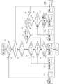
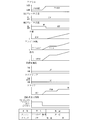
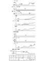
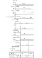
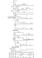
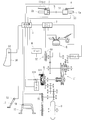
- the schematic diagram which shows the concept of the saddle riding type vehicle which concerns on the 1st Embodiment of this invention Schematic diagram showing the overall configuration of the saddle-ride type vehicle Table showing the starting conditions and control details when starting the engine from the idle stop state in the saddle-ride type vehicle
- the saddle-ride type vehicle includes a two-wheeled vehicle that can be driven by steering with a handlebar while a driver sits on a seating seat, and as shown in FIGS. Handlebar H, first brake means 8 and second brake means 9 comprising two operating means for performing a braking operation, transmission 1 comprising a stepped transmission, clutch K, and engine control means
- the engine ECU 2, the transmission ECU 3, and the shift operation means 7 are configured.
- symbol ST in the figure has shown the starter for starting the engine E.
- the handlebar H is a steering grip with a grip grip Gb that can be gripped by the driver with a left hand and a throttle grip Ga that can be operated by an accelerator by rotating while gripping with the right hand.
- a shift operation means 7 for setting the transmission 1 (stepped transmission) to a desired mode is attached to the distal end portion (the position on the proximal end side of the gripping grip Gb) on which Gb is attached.
- the mode of the transmission 1 (N range, D range, and L range) can be arbitrarily switched and operated by the driver arbitrarily operating the shift operation means 7 with the hand holding the grip grip Gb. .
- the slot grip Ga can be operated by an accelerator by being rotated by a predetermined angle while being gripped by a driver, and a desired fuel is supplied to the engine E by opening / closing a throttle (fuel injection valve) of the vehicle according to the rotation angle.
- the engine E can be driven at a desired rotational speed.
- a switch case capable of operating various electrical components of the two-wheeled vehicle is attached to the base end side of the throttle grip Ga in the handlebar H.
- the first brake means 8 is attached to the distal end of the handle bar H on the side where the throttle grip Ga is attached (extending from the base end side position of the throttle grip Ga).
- the first brake means 8 is composed of an operation lever that can be swung by the driver arbitrarily holding the throttle grip Ga, and when the swing operation is detected by the brake operation detection sensor S1, For example, a two-wheeled vehicle can be braked by operating a brake for a front wheel (not shown).
- the two-wheeled vehicle according to the present embodiment is provided with second brake means 9 composed of operating means that can be operated by the driver's feet.
- the second brake means 9 is composed of a foot brake that can be operated with the foot of a driver who sits straddling the seat 10, and when the operation is detected by the brake operation detection sensor S2, for example, for a rear wheel (not shown)
- the two-wheeled vehicle can be braked by operating the brake.
- the driver straddles the detection sensors S6 and S5 that detect the state (operating state or non-operating state) of the main stand 12 and the side stand 11 that hold the vehicle in an inverted state. It has a detection sensor S4 that detects the presence or absence of seating on the seat 10 that can be seated, and a detection sensor S3 that detects the presence or absence of gripping of the throttle grip Ga (non-contact with the throttle grip Ga).
- the detection sensor S3 may be configured to detect whether or not the grip grip Gb is gripped (non-contact with the grip grip Gb).
- These detection sensors (S3 to S6) are electrically connected to the transmission ECU 3, and can transmit detection signals to the transmission ECU.
- the clutch K and the transmission 1 are disposed in the middle of the power transmission system for the drive wheels D of the engine E.
- the transmission 1 according to the present embodiment can be automatically set to a predetermined shift stage according to the mode set by the shift operation means 7, and is composed of a stepped transmission having a dog clutch.
- the transmission 1 is controlled by the shift control means 4, and in the D range (in this embodiment, 1st speed ⁇ ⁇ 2nd speed ⁇ ⁇ 3rd speed ⁇ 4th speed automatic shift) and L range (2nd speed ⁇ 3rd speed However, normally it is fixed at 2nd speed, and when it is set to 3rd speed only in the high speed D ⁇ L range), the driving force of the engine E is transmitted to the driving wheel D and N In the range (neutral), the driving force of the engine E is not transmitted to the driving wheels D.
- D range in this embodiment, 1st speed ⁇ ⁇ 2nd speed ⁇ ⁇ 3rd speed ⁇ 4th speed automatic shift
- L range 2nd speed ⁇ 3rd speed
- the clutch K is disposed between the engine E and the transmission 1 in the power transmission system and is controlled by the clutch control means 5 to transmit or cut off the driving force of the engine E to the drive wheels D at an arbitrary timing.
- it is configured by a multi-plate clutch. Then, the clutch control means 5 transmits the driving force of the engine E to the driving wheel D (the clutch plate is pressed by the pressure), and the transmission of the driving force of the engine E is cut off and transmitted to the driving wheel D.
- the switching operation can be performed in an off state in which the clutch plate is not pressed by the pressure.
- the clutch K includes a clutch position angle sensor S10 and a clutch rotation sensor S11, and detection signals from the clutch position angle sensor S10 and the clutch rotation sensor S11 are transmitted to the transmission ECU 3. It has become. With this detection signal, the pressure contact state of the clutch plate can be grasped, and the clutch capacity (TC) of the clutch K can be detected.
- the engine ECU 2 (engine control means) is composed of a microcomputer or the like that can control the engine E, and is connected to a battery B mounted on the vehicle and supplied with power, and is also electrically connected to the transmission ECU 3. Therefore, it is possible to send and receive electrical signals. Further, the engine ECU 2 according to the present embodiment is configured to automatically stop the engine and idle stop when a predetermined condition is satisfied. This idle stop refers to control that can stop idling (low rotation) of the engine E and suppress fuel consumption when a predetermined condition is satisfied.
- the transmission ECU 3 is composed of, for example, a microcomputer like the engine ECU 2 and is electrically connected to the engine ECU 2 so as to be able to transmit and receive a predetermined electric signal, and also to the transmission 1 and the actuator of the clutch K, respectively.
- the transmission control means 4 for controlling the transmission 1 the clutch control means 5 for controlling the clutch K, and the judging means 6, as shown in FIG. It is comprised.
- the transmission ECU 3 can detect the vehicle speed sensor S7 that can detect the vehicle speed and the shift clutch angle that can detect the state of the dog clutch of the transmission 1 (power transmission state or power transmission is interrupted). It is electrically connected to the sensor S8 so that the vehicle speed and the state of the dog clutch can be grasped.
- symbol S9 in the figure has shown the engine rotation sensor electrically connected with engine ECU2.
- the determination unit 6 when the engine E is started from the idling stop state, the determination unit 6 according to the present embodiment can determine the driver's request based on the operation state of the driver with respect to the vehicle.
- the clutch control unit 5 Controls the clutch K or the transmission 1 according to the driver's request determined by the determination means 6 to transmit the driving force of the engine E to the drive wheels, and the engine E can travel. It is possible to arbitrarily select a stop state in which the stop can be maintained without substantially transmitting the drive force to the drive wheels (that is, without transmitting power that substantially contributes to traveling).
- steady traveling control having start control or shift control when the accelerator operation is performed, and creep control (power transmission system) that allows the engine E to travel in the idling state without the accelerator operation. Is controlled according to the driver's request determined by the determination means 6, and the transmission is in a stopped state.
- the neutral control for setting 1 to neutral and the idle neutral control for setting, for example, the D range and maintaining the stop state of the vehicle in the idling state are selectively performed according to the driver's request determined by the determination means 6. To be done.
- the idle stop is canceled by satisfying a predetermined condition (for example, when both the first brake means 8 and the second brake means 9 are not operated).
- a predetermined condition for example, when both the first brake means 8 and the second brake means 9 are not operated.
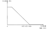
- the invalid stroke filling control of the clutch K (control to move the clutch position angle to ⁇ C0 so that the clutch capacity (TC) in FIG. 7 immediately before rising) is performed. It has become. Thereby, in idle neutral control, when accelerator operation is performed, the start time lag of a vehicle can be suppressed.
- the start control and the creep control in the running state are such that the driving force of the engine E is transmitted to the drive wheels D by controlling the clutch K or the transmission 1 during engine startup. It has become.
- the determination means 6 according to the present embodiment can be brought into a stopped state based on detection by the detection sensors (S3 to S6). That is, the detection sensor S3 detects that the driver is not gripping the throttle grip Ga (or the grip grip Gb), and the detection sensor S4 detects that the driver has left the seating seat 10, or the detection sensor S5. When it is detected by S6 that the vehicle has been turned upside down at the side stand 11 or the main stand 12, the determination means 6 determines that the driver's request is a stop, so that the stop state is based on the determination. It is.
- the idle stop is performed on the condition that the accelerator operation is performed or that both the first brake means 8 and the second brake means 9 are not operated.
- the engine can be started from this state.
- start control is performed, and when both the first brake means 8 and the second brake means 9 are in a non-operating state, creep control or idle Neutral control will be performed.
- both the first brake means 8 and the second brake means 9 are brought into the non-operating state, and then the detection switch (for example, the detection switch S5 of the side stand 11) is turned on.
- the detection switch for example, the detection switch S5 of the side stand 11
- idle neutral control is performed until both the first brake means 8 and the second brake means 9 are in the non-operating state until the detection switch is turned off.
- the creep control is performed from when the detection switch is turned off until the accelerator operation is performed, and the start control is performed after the accelerator operation.
- the two-wheeled vehicle as the saddle-ride type vehicle according to the present embodiment has the following configuration in addition to the above configuration. That is, the determination means 6 according to the present embodiment can determine whether or not the simultaneous operation of the first brake means and the second brake means has been performed. The determination means 6 uses the first brake means 8 and the second brake means. On the condition that it is determined that the simultaneous operation of the brake means 9 (the state where both the first brake means 8 and the second brake means 9 are operated by the driver) has been performed, the engine ECU 2 (engine control) The idle stop by means) is performed.
- the determination means 6 is formed at the tip of the handlebar H on the side where the second brake means 9 is operated and the first brake means 8 (the throttle grip Ga is attached). When the operation means) is operated continuously for a predetermined time, it is determined that the simultaneous operation of the first brake means 8 and the second brake means 9 has been performed. The determination means 6 performs the simultaneous operation of the first brake means 8 and the second brake means 9 when the second brake means 9 is operated and when the first brake means 8 is operated. You may make it judge that it was broken.
- the determination means 6 can determine that the vehicle is below a predetermined vehicle speed by an electrical signal from the vehicle speed sensor S7, and the first brake means 8 and the second brake means 9
- the engine ECU 2 engine control means performs idle stop (during deceleration and when the vehicle is stopped) on condition that it is determined to be equal to or less than the predetermined vehicle speed (also referred to as “idle stop reception vehicle speed”). (Idle stop) is performed.
- the clutch control means 5 is capable of performing creep control that allows the vehicle to travel by controlling the clutch K when the engine E is idling without the accelerator operation. Creep by the clutch control means 5 on condition that the accelerator means of the throttle grip Ga is not operated and the determination means 6 determines that the first brake means 8 and the second brake means 9 are not simultaneously operated when the vehicle speed is lower than the vehicle speed. It is comprised so that control may be performed.
- the determination means 6 determines that the dog clutch of the transmission 1 (stepped transmission) is in the power transmission state and that the first brake means 8 and the second brake means 9 are operated simultaneously. On the condition that this is done, the engine ECU 2 (engine control means) is configured to perform idle stop. This makes it possible to accurately select the gear position according to the vehicle speed, etc., and to start the vehicle more quickly and smoothly when starting the engine E from the idle stop state. it can.
- the determination means 6 determines that the driver's request is the creep control After the determination, when the operation by the first brake means 8 is performed, creep control (idle speed) is performed only during the operation of the second brake means 9, and the first brake means 8 and the second brake means. After 9 simultaneous operations, idle stop (fuel cut) is performed.
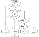
- step S12 idle stop maintenance control is performed. If no detection switch (S3 to S6) is detected in S6, it is determined that the driver's request is low speed travel (travel due to a creep phenomenon) that does not depend on the accelerator operation, and creep control is performed in S14. Let it be done.
- the driver's request is a low speed that does not depend on the accelerator operation. It is determined that the vehicle is traveling (traveling by a creep phenomenon), and creep control is performed in S14. If the vehicle speed is not equal to or lower than the predetermined vehicle speed (idle stop acceptance vehicle speed) in S8, the process proceeds to S16, where steady travel control (in this case, control for normal travel) is performed.
- S3 If it is determined in S3 that the driver's request is an idle stop, whether there is an increase in vehicle speed (S4), whether the idle stop has elapsed for a predetermined time (S5), It is sequentially determined whether or not the amount is less than the predetermined amount (S6). If any one of them is satisfied, the engine is started in S12. Further, if it is determined in S2 that the engine is not idling, the process proceeds to S7, where it is determined whether or not the engine is being started. If the engine is being started, the process proceeds to S8 and whether or not the engine has been started. To be judged.
- the routine proceeds to S9 where it is determined whether or not the driver's request is an idle stop, and the driver's request is an idle stop. If it is determined that it is not, normal operation is maintained in S13. If it is determined in S9 that the driver's request is an idle stop, whether or not the dog clutch of the transmission 1 is in the first speed or the second speed (S10), and the condition for the idle stop is established. Whether or not (S11) is sequentially judged and if both are satisfied, the engine is idle-stopped in S14, and if either is not satisfied, the process proceeds to S13 and normal operation is performed.
- S2 If it is determined in S2 that the driver's request is an idle stop, the process proceeds to S3, where it is determined whether the engine is in an idle stop. Off (state where engine driving force is not transmitted to the drive wheels) and when idling stop is not being performed (for example, the driver's request is idling stop, but idling cannot be stopped due to various conditions such as remaining battery level) ), Idle neutral control is performed in S6.
- the process proceeds to S4 to determine whether or not the driver's request is neutral. If the driver's request is neutral, the process proceeds to S7 and the clutch K is turned off ( The engine drive force is not transmitted to the drive wheels). If the driver's request is not neutral in S4, it is determined in S5 whether or not the driver's request is creep control. If the driver's request is creep control, creep control is performed in S8. In addition, if the driver's request is not creep control, the clutch control during normal travel (start control at start) is performed in S9.
- idle neutral control by the clutch control means 5 will be described based on the graph of FIG. 7 and the flowchart of FIG.
- the actuator is operated based on detection signals from the clutch position angle sensor S10 and the clutch rotation sensor S11 of the clutch K, and invalid stroke filling control is performed.
- the invalid stroke filling control is a control performed by setting the clutch position angle to ⁇ C0 so that the clutch capacity (TC) is in a state immediately before rising from 0.
- the creep control is a control for moving the vehicle while the engine E is idling without an accelerator operation, and enables low-speed traveling that does not depend on the accelerator operation.
- the creep control is performed by setting the clutch position angle to ⁇ C1 so that the clutch capacity (TC) becomes a predetermined value.
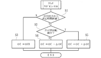
- the feedback control for maintaining the idle speed is as follows. That is, in determination (S2) whether the idle speed of the engine E is equal to or greater than the predetermined value (1) and determination (S3) whether the idle speed of the engine E is equal to or less than the predetermined value (2). If the engine idling speed is greater than or equal to the predetermined value (1) in S2, the process proceeds to S5 to reduce the amount of air supplied to the engine E to reduce the idling speed, and in S3 the engine idling When the rotational speed is equal to or less than the predetermined value (2), the process proceeds to S6, the amount of air supplied to the engine E is increased, and the idle rotational speed is increased.
- feedback control for maintaining the clutch capacity is as follows. That is, in S4, it is determined whether or not the fuel (injected fuel) supplied to the engine E is equal to or greater than a predetermined value. If the injected fuel is not equal to or greater than the predetermined value, a small angle ( ⁇ C) The clutch position angle is set to a value obtained by subtracting ( ⁇ C) ( ⁇ C ⁇ C), the clutch capacity is increased, and if the injected fuel is greater than or equal to a predetermined value, the clutch position angle ( ⁇ C) is set to a small angle ( ⁇ C) in S7. ) Is added to the value ( ⁇ C + ⁇ C) to reduce the clutch capacity.
- clutch control start control in the case of start
- the clutch control during traveling is control for traveling or starting the vehicle based on an accelerator operation or the like.
- shifting operation means 7 S1
- shifting control for shifting is performed in S9. It is then determined whether or not the clutch differential rotation is within a predetermined value.
- the feedback control during driving is as follows. That is, it is determined whether or not the rotational speed of the engine E is equal to or greater than a predetermined value (S4). If the rotational speed is equal to or greater than the predetermined value, a value obtained by subtracting a minute angle ( ⁇ C) from the clutch position angle ( ⁇ C) in S6. A value obtained by adding a minute angle ( ⁇ C) to the clutch position angle ( ⁇ C) in S7 when the clutch position angle is set to ( ⁇ C ⁇ C), the clutch capacity is increased, and the rotational speed is not greater than or equal to a predetermined value (S7).
- the clutch position angle is set to ⁇ C + ⁇ C) to reduce the clutch capacity.
- the saddle-ride type vehicle according to the present embodiment is a two-wheeled vehicle that can be driven by a driver while steering over a seating seat and is driven by a handlebar.
- first brake means 8 and second brake means 13 comprising two operation means for performing a braking operation, transmission 1 ′ comprising a continuously variable transmission, clutch K, and engine as engine control means
- the ECU 2, the transmission ECU 3, and the shift operation means 7 are configured. Note that the same components as those in the first embodiment are denoted by the same reference numerals, and detailed description thereof is omitted.
- the second brake means 13 is attached to the distal end of the handle bar H on the side where the grip grip Gb is attached (extending from the base end side position of the grip grip Gb). Similar to the first brake means 8, the second brake means 13 is composed of an operation lever that can be freely swung by a driver holding the grip grip Gb, and the swing operation is detected by a brake operation detection sensor. When detected in S12, for example, a brake for a rear wheel (not shown) is operated to brake the two-wheeled vehicle.
- the transmission 1 ′ is a continuously variable transmission (CVT) that can be automatically set to a predetermined shift ratio according to the mode set by the shift operation means 7.
- the transmission 1 ′ is controlled by the shift control means 4, and when the D range and the L range are set, the driving force of the engine E is transmitted to the drive wheels D and the N range.
- the clutch is turned off by the clutch control and the shift control (pulley control), the belt side pressure is not applied, and the driving force is not transmitted to the driving wheel D by interrupting the transmission of the driving force at two locations. It is in a state.
- the transmission ratio of the transmission 1 ′ (continuously variable transmission) is equal to or greater than a predetermined value and that the first brake means 8 and the second brake means 13 are operated simultaneously.
- the engine ECU 2 engine control means
- the engine ECU 2 is configured to perform an idle stop on condition that the means 6 has determined. Thereby, the shift stage can be switched more smoothly, and more quickly and smoothly when starting the engine E from the idle stop state and starting the vehicle.
- the determination unit 6 that can determine the request of the driver based on the operation state of the driver with respect to the vehicle; By controlling the clutch K according to the driver's request determined by the determination means 6, the driving state of the engine E is transmitted to the driving wheel D and the traveling state in which the vehicle can travel and the driving force of the engine E is driven to the driving wheel.
- the clutch control means 5 that can arbitrarily select a stop state in which the stop can be maintained without being substantially transmitted to D is provided, when the engine E is started from the idle stop state, for example, a driver's request is When driving (starting), it is possible to start the vehicle quickly according to the accelerator operation by selecting the driving state, and when the driver's request is stopping, select the stopping state. It is possible to surely perform the stop of the vehicle. Therefore, when the engine E is started from the idling stop state, the driver's request is determined based on the operation state of the driver with respect to the vehicle, so that finer control corresponding to the driver's request can be performed. .
- the first brake is composed of two operation means for performing a braking operation, at least one of which is formed at the tip of the handlebar H.
- a state of idling stop provided that the first brake means 8 and the second brake means (9, 13) are both in the non-operating state, including the means 8 and the second brake means (9, 13). Therefore, the engine stop can be started and released more smoothly and reliably in response to the driver's request.
- the start control when the accelerator operation is performed in response to the driver's request, which is determined by the judging means 6 is the start control when the accelerator operation is performed and the creep control that allows the engine E to run in the idling state without the accelerator operation. Since it is selectively performed, when starting the engine E from the idling stop state, the vehicle can be started quickly according to the accelerator operation, and when the driver's request is creep control, the vehicle is driven at a low speed. Can be started, and a delicate accelerator operation can be dispensed with.
- the vehicle is provided with a shift control means 4 for controlling the transmission of the vehicle, and in the stop state, the neutral control for making the transmission (1, 1 ′) neutral, and the stop state of the vehicle in the idling state are maintained. Since the idle neutral control is selectively performed according to the driver's request determined by the determination means 6, it is possible to perform more fine control corresponding to the driver's request.
- the start control and creep control control control the clutch K to transmit the driving force of the engine E to the drive wheels during engine startup, so that the vehicle starts or creeps more quickly and smoothly.
- a detection sensor (S3 to S6) for detecting the state of the main stand 12 or the side stand 11, the presence / absence of sitting on the seating seat 10, or the presence / absence of gripping of the grip grip Gb or the throttle grip Ga is provided, and determination means 6 Since the vehicle can be stopped based on detection of at least one of the detection sensors (S3 to S6), it is possible to reliably determine the driver's request and hold the vehicle stopped.
- the idle neutral control is performed, so that the driver's request is not required. In this case, it is possible to reliably prevent the vehicle from starting, and improve safety.
- the determination means that can determine whether or not the simultaneous operation of the first brake means 8 and the second brake means (9, 13) has been performed. 6 and the engine ECU 2 (during the vehicle decelerating travel) on the condition that the determination means 6 determines that the first brake means 6 and the second brake means (9, 13) are operated simultaneously. Since the engine control means) performs the idle stop, the idle stop during the deceleration traveling corresponding to the driver's request can be performed.
- the first brake means 8 is composed of operation means formed at the front end of the handle bar H on the side where the throttle grip Ga is attached, the first brake means 8 is added to the second brake means (9, 13).
- the means 8 When the means 8 is operated, it can be determined that the accelerator operation by the throttle grip Ga is not performed, and it can be determined that the driver's request is to cause an idle stop. Therefore, it is possible to reliably perform idling stop during deceleration traveling corresponding to the driver's request.
- the determination means 6 is configured to operate the first brake means 8 and the second brake when the second brake means (9, 13) is operated and the first brake means 8 is continuously operated for a predetermined time. Since it is determined that the simultaneous operation of the means (9, 13) has been performed, it can be determined that the accelerator operation by the throttle grip Ga is not performed for a predetermined time, and the driver's request is to cause an idle stop. I can judge. Therefore, it is possible to more reliably cause idle stop during deceleration traveling corresponding to the driver's request.
- the determination means 6 can determine that the vehicle is below a predetermined vehicle speed (idle stop acceptance vehicle speed) and simultaneously operate the first brake means 8 and the second brake means (9, 13).
- the engine ECU 2 engine control means
- the timing for the idle stop can be arbitrarily set by the designer. The degree of freedom can be improved.
- clutch control means 5 that can perform creep control that can run by controlling the clutch while the engine is idling without an accelerator operation, and when the vehicle speed is below a predetermined vehicle speed, there is no accelerator operation of the throttle grip Ga.
- the creep control by the clutch control means 5 is performed on the condition that the determination means 6 determines that there is no simultaneous operation of the first brake means 8 and the second brake means (9, 13). It is possible to selectively perform idle stop and creep control corresponding to the above.
- the present invention is not limited to these.
- the first brake unit 8 and the second brake unit (9) are determined by the determination unit 6 as a condition for performing an idle stop. , 13) is not limited to the determination that the simultaneous operation has been performed, and other various conditions can be applied.
- the first brake means 8 is not limited to the operation means formed at the distal end portion of the handle bar H on the side where the throttle grip Ga is attached, and is composed of the operation means formed at other positions. It may be.
- the present invention may be applied to other forms of vehicles instead of two-wheeled vehicles, as long as they are saddle riding type vehicles that can be driven by steering with the handlebars while sitting over a seating seat.
- a determination unit that can determine a driver's request based on a driver's operation state with respect to the vehicle, and a clutch that is controlled according to the driver's request determined by the determination unit
- a clutch capable of arbitrarily selecting a traveling state in which the driving force of the engine can be transmitted to the driving wheels and a stopping state in which the stopping can be maintained without substantially transmitting the driving force of the engine to the driving wheels.
- the present invention can be applied to a vehicle having a different external shape or a vehicle to which other functions are added.
Landscapes
- Engineering & Computer Science (AREA)
- Mechanical Engineering (AREA)
- Chemical & Material Sciences (AREA)
- Combustion & Propulsion (AREA)
- General Engineering & Computer Science (AREA)
- Transportation (AREA)
- Control Of Vehicle Engines Or Engines For Specific Uses (AREA)
- Control Of Transmission Device (AREA)
- Control Of Driving Devices And Active Controlling Of Vehicle (AREA)
Abstract
Description
第1の実施形態に係る鞍乗り型車両は、運転者が着座シートに跨って着座しつつハンドルバーで操舵して走行可能な二輪車から成り、図1、2に示すように、エンジンEと、ハンドルバーHと、制動操作を行うための2つの操作手段から成る第1ブレーキ手段8及び第2ブレーキ手段9と、有段変速機から成る変速機1と、クラッチKと、エンジン制御手段としてのエンジンECU2と、変速機ECU3と、変速操作手段7とを有して構成されている。なお、図中符号STは、エンジンEを始動させるためのスタータを示している。
すなわち、本実施形態に係る判断手段6は、第1ブレーキ手段及び第2ブレーキ手段の同時操作が行われたか否かを判断し得るもので、当該判断手段6で第1ブレーキ手段8及び第2ブレーキ手段9の同時操作(運転者による第1ブレーキ手段8と第2ブレーキ手段9とを共に操作した状態)が行われたと判断されたことを条件として、車両の減速中にエンジンECU2(エンジン制御手段)によるアイドルストップを行わせるよう構成されている。
先ず、変速操作手段7によって変速レンジがDレンジ又はLレンジに設定されているか否かを判断し(S1)、Dレンジ又はLレンジに設定されていない場合(すなわち、Nレンジに設定されている場合)は、S11に進んでニュートラル制御が行われるとともに、Dレンジ又はLレンジに設定されている場合、S2に進み、アクセル操作がなされたか否かが判断される。
先ず、イグニッションスイッチがオンしているか否かが判断され(S1)、イグニッションスイッチがオンしている場合、アイドルストップ中であるか否か判断される(S2)。S2にてアイドルストップ中であると判断されると、S3に進んで運転者の要求がアイドルストップである(判断手段6が「アイドルストップ維持制御」を判断)か否か判断され、運転者の要求がアイドルストップでないと判断されると、S12にてエンジンを始動させる。
先ず、運転者の要求がアイドルニュートラル制御か否か判断され(S1)、アイドルニュートラル制御の場合、S6にてアイドルニュートラル制御を行わせるとともに、当該運転者の要求がアイドルニュートラル制御でない場合、S2に進んで運転者の要求がアイドルストップであるか否か判断する。
アイドルニュートラル制御においては、クラッチKのクラッチ位置角度センサS10及びクラッチ回転センサS11による検知信号に基づいてアクチュエータを作動させ、無効ストローク詰め制御が行われる。かかる無効ストローク詰め制御は、図7に示すように、クラッチ容量(TC)が0から立ち上がる直前の状態とすべくクラッチ位置角度をΘC0に設定して行われる制御である。
クリープ制御は、既述のように、アクセル操作がなくエンジンEがアイドリングの状態で車両を動かす制御であり、アクセル操作によらない低速走行を可能とするものである。かかるクリープ制御は、図7に示すように、クラッチ容量(TC)が所定値となるようにクラッチ位置角度をΘC1に設定して行われる制御である。
走行時のクラッチ制御は、既述のように、アクセル操作等に基づいて車両を走行又は発進させるための制御である。先ず、変速操作手段7の操作による変速中であるか否かが判断され(S1)、変速中であれば、S9にて変速のための変速制御が行われるとともに、変速中でない場合、S2に進んでクラッチ差回転が所定値以内か否かが判断される。
本実施形態に係る鞍乗り型車両は、運転者が着座シートに跨って着座しつつハンドルバーで操舵して走行可能な二輪車から成り、図16、17に示すように、エンジンEと、ハンドルバーHと、制動操作を行うための2つの操作手段から成る第1ブレーキ手段8及び第2ブレーキ手段13と、無段変速機から成る変速機1’と、クラッチKと、エンジン制御手段としてのエンジンECU2と、変速機ECU3と、変速操作手段7とを有して構成されている。なお、第1の実施形態と同様の構成要素には同一の符号を付すこととし、それらの詳細な説明を省略する。
1’ 変速機(無段変速機)
2 エンジンECU(エンジン制御手段)
3 変速機ECU
4 変速制御手段
5 クラッチ制御手段
6 判断手段
7 変速操作手段
8 第1ブレーキ手段
9 第2ブレーキ手段
10 着座シート
11 サイドスタンド
12 メインスタンド
13 第2ブレーキ手段
H ハンドルバー
E エンジン
Claims (9)
- 運転者が把持し得る把持グリップ及び把持しつつアクセル操作可能なスロットルグリップがそれぞれ先端部に取り付けられたハンドルバーと、
エンジンを自動的に停止させてアイドルストップさせるエンジン制御手段と、
エンジンの駆動力を駆動輪に対して任意タイミングで伝達又は遮断可能なクラッチと、
を具備し、運転者が着座シートに跨って着座しつつ前記ハンドルバーで操舵して走行可能な鞍乗り型車両において、
アイドルストップの状態からエンジンを始動させる際、運転者の車両に対する操作状況に基づき運転者の要求を判断し得る判断手段と、
該判断手段で判断された運転者の要求に応じて前記クラッチを制御することにより、エンジンの駆動力を駆動輪に伝達させて走行可能な走行状態と、エンジンの駆動力を駆動輪に実質的に伝達させず停車が維持され得る停車状態とを任意に選択可能なクラッチ制御手段と、
を備えたことを特徴とする鞍乗り型車両。 - 制動操作を行うための2つの操作手段から成り、そのうち少なくとも何れか一方が前記ハンドルバーの先端部に形成された第1ブレーキ手段及び第2ブレーキ手段を具備するとともに、当該第1ブレーキ手段及び第2ブレーキ手段が共に非操作状態とされたことを条件として、アイドルストップの状態からエンジンを始動させ得ることを特徴とする請求項1記載の鞍乗り型車両。
- 前記走行状態においては、アクセル操作がなされた際の発進制御又は変速制御を有する定常走行制御と、アクセル操作がなくエンジンがアイドリングの状態で走行可能なクリープ制御とが前記判断手段で判断された運転者の要求に応じて選択的に行われることを特徴とする請求項1又は請求項2記載の鞍乗り型車両。
- 車両の変速機を制御する変速制御手段を具備するとともに、前記停車状態においては、変速機をニュートラルにするニュートラル制御と、アイドリングの状態で車両の停止状態を維持させるアイドルニュートラル制御とが前記判断手段で判断された運転者の要求に応じて選択的に行われることを特徴とする請求項1~3の何れか1つに記載の鞍乗り型車両。
- 前記走行状態は、エンジン始動中に、前記クラッチを制御してエンジンの駆動力を駆動輪に伝達させる状態とすることを特徴とする請求項1~4の何れか1つに記載の鞍乗り型車両。
- メインスタンド若しくはサイドスタンドの状態、着座シートへの着座の有無、又は前記把持グリップ若しくはスロットルグリップの把持の有無を検知する検知センサを具備するとともに、前記判断手段は、当該検知センサの少なくとも何れか1つの検知に基づいて前記停車状態とし得ることを特徴とする請求項1~5の何れか1つに記載の鞍乗り型車両。
- 運転者の操作によらずアイドルストップの状態からエンジンを始動させる際、前記アイドルニュートラル制御を行わせることを特徴とする請求項4~6の何れか1つに記載の鞍乗り型車両。
- 前記変速機は、有段変速機から成ることを特徴とする請求項1~7の何れか1つに記載の鞍乗り型車両。
- 前記変速機は、無段変速機から成ることを特徴とする請求項1~7の何れか1つに記載の鞍乗り型車両。
Priority Applications (3)
| Application Number | Priority Date | Filing Date | Title |
|---|---|---|---|
| DE112014003417.7T DE112014003417B9 (de) | 2013-07-25 | 2014-07-23 | Fahrzeug vom Satteltyp |
| CN201480041975.7A CN105408603B (zh) | 2013-07-25 | 2014-07-23 | 鞍乘型车辆 |
| US15/005,786 US10099748B2 (en) | 2013-07-25 | 2016-01-25 | Saddle-type vehicle |
Applications Claiming Priority (2)
| Application Number | Priority Date | Filing Date | Title |
|---|---|---|---|
| JP2013154796A JP6147127B2 (ja) | 2013-07-25 | 2013-07-25 | 鞍乗り型車両 |
| JP2013-154796 | 2013-07-25 |
Related Child Applications (1)
| Application Number | Title | Priority Date | Filing Date |
|---|---|---|---|
| US15/005,786 Continuation US10099748B2 (en) | 2013-07-25 | 2016-01-25 | Saddle-type vehicle |
Publications (1)
| Publication Number | Publication Date |
|---|---|
| WO2015012325A1 true WO2015012325A1 (ja) | 2015-01-29 |
Family
ID=52393358
Family Applications (1)
| Application Number | Title | Priority Date | Filing Date |
|---|---|---|---|
| PCT/JP2014/069487 Ceased WO2015012325A1 (ja) | 2013-07-25 | 2014-07-23 | 鞍乗り型車両 |
Country Status (5)
| Country | Link |
|---|---|
| US (1) | US10099748B2 (ja) |
| JP (1) | JP6147127B2 (ja) |
| CN (1) | CN105408603B (ja) |
| DE (1) | DE112014003417B9 (ja) |
| WO (1) | WO2015012325A1 (ja) |
Families Citing this family (4)
| Publication number | Priority date | Publication date | Assignee | Title |
|---|---|---|---|---|
| US9216789B2 (en) * | 2012-11-12 | 2015-12-22 | Indian Motorcycle International, LLC | Two-wheeled vehicle |
| US9394859B2 (en) | 2012-11-12 | 2016-07-19 | Indian Motorcycle International, LLC | Two-wheeled vehicle |
| JP6622633B2 (ja) * | 2016-03-17 | 2019-12-18 | 本田技研工業株式会社 | 鞍乗型車両 |
| CN112455594B (zh) * | 2020-11-30 | 2022-04-15 | 广东高标电子科技有限公司 | 一种小型电动交通工具怠速控制方法和小型电动交通工具 |
Citations (8)
| Publication number | Priority date | Publication date | Assignee | Title |
|---|---|---|---|---|
| JP2008213699A (ja) * | 2007-03-06 | 2008-09-18 | Toyota Motor Corp | 車両の運転制御装置および運転制御方法 |
| JP2009012520A (ja) * | 2007-07-02 | 2009-01-22 | Nissan Motor Co Ltd | アイドルストップ車の駆動装置 |
| JP2010058769A (ja) * | 2008-09-08 | 2010-03-18 | Honda Motor Co Ltd | 電動車両における制御装置 |
| JP2010223263A (ja) * | 2009-03-19 | 2010-10-07 | Mitsubishi Motors Corp | 車両の制御装置 |
| JP2012122497A (ja) * | 2010-12-06 | 2012-06-28 | Toyota Motor Corp | 車両制御装置 |
| WO2012128021A1 (ja) * | 2011-03-18 | 2012-09-27 | 本田技研工業株式会社 | エンジン制御装置及びエンジン制御方法 |
| WO2012164677A1 (ja) * | 2011-05-31 | 2012-12-06 | 本田技研工業株式会社 | エンジン制御装置 |
| JP2012255384A (ja) * | 2011-06-09 | 2012-12-27 | Mitsubishi Motors Corp | 車両の制御装置 |
Family Cites Families (24)
| Publication number | Priority date | Publication date | Assignee | Title |
|---|---|---|---|---|
| US4315659A (en) * | 1979-03-30 | 1982-02-16 | Honda Giken Kogyo Kabushiki Kaisha | Vehicular anti-skid brake device |
| JPS57211918A (en) * | 1981-06-23 | 1982-12-25 | Tokyo Shibaura Electric Co | Method and device for treating terminal of wire cable |
| US4991679A (en) * | 1985-06-21 | 1991-02-12 | Honda Giken Kogyo Kabushiki Kaisha | Four wheel-drive anti-locking braking |
| US4739236A (en) * | 1985-12-05 | 1988-04-19 | Russel H. Keyes | Portable helm |
| US5321407A (en) * | 1991-12-27 | 1994-06-14 | Honda Giken Kogyo Kabushiki Kaisha | Method for estimating relative speed between vehicle and objective obstacle |
| JP3571409B2 (ja) * | 1995-04-03 | 2004-09-29 | 本田技研工業株式会社 | 自動変速機の変速制御装置 |
| JP4111365B2 (ja) * | 1999-06-07 | 2008-07-02 | 本田技研工業株式会社 | エンジン自動停止始動制御装置 |
| JP3832196B2 (ja) * | 2000-06-02 | 2006-10-11 | 三菱自動車工業株式会社 | 自動変速機の変速制御装置 |
| EP1258658A3 (en) * | 2001-05-14 | 2009-07-15 | Nissan Motor Company, Limited | Auxiliary Transmission |
| JP4392788B2 (ja) | 2004-02-12 | 2010-01-06 | 本田技研工業株式会社 | 自動アイドル停止車両 |
| TWI341362B (en) * | 2004-02-18 | 2011-05-01 | Yamaha Motor Co Ltd | Saddle type vehicle, and engine controlling apparatus and idle stop canceling method for the saddle type vehicle |
| JP4859042B2 (ja) | 2006-08-31 | 2012-01-18 | 本田技研工業株式会社 | アイドルストップ制御装置 |
| JP2008232368A (ja) * | 2007-03-23 | 2008-10-02 | Univance Corp | 駆動力配分装置 |
| JP2010163879A (ja) | 2009-01-13 | 2010-07-29 | Honda Motor Co Ltd | アイドルストップ制御装置 |
| JP5361590B2 (ja) * | 2009-07-21 | 2013-12-04 | 本田技研工業株式会社 | エンジン始動制御装置 |
| WO2011024928A1 (ja) * | 2009-08-24 | 2011-03-03 | Kawanishi Eiji | 圧力負荷装置を有する天秤使用の重力発電装置と連結するハイブリッド発電装置。 |
| JP5177162B2 (ja) * | 2010-03-30 | 2013-04-03 | アイシン・エィ・ダブリュ株式会社 | 自動変速機の制御装置 |
| JP5621479B2 (ja) | 2010-09-29 | 2014-11-12 | 株式会社アドヴィックス | 車両の制御装置及び制御方法 |
| JP5720383B2 (ja) | 2011-04-06 | 2015-05-20 | スズキ株式会社 | 自動二輪車用アイドリングストップ制御装置およびこれを備える自動二輪車 |
| JP5711604B2 (ja) | 2011-05-10 | 2015-05-07 | 本田技研工業株式会社 | 車両の駆動制御装置 |
| JP5660733B2 (ja) | 2012-02-27 | 2015-01-28 | 株式会社エフ・シー・シー | 動力伝達装置 |
| US9840306B2 (en) * | 2012-10-03 | 2017-12-12 | Kawasaki Jukogyo Kabushiki Kaisha | Electric vehicle, and battery pack |
| JP6147128B2 (ja) * | 2013-07-25 | 2017-06-14 | 株式会社エフ・シー・シー | 鞍乗り型車両 |
| JP6376662B2 (ja) * | 2015-05-12 | 2018-08-22 | 株式会社エフ・シー・シー | 車両用動力伝達システム |
-
2013
- 2013-07-25 JP JP2013154796A patent/JP6147127B2/ja not_active Expired - Fee Related
-
2014
- 2014-07-23 CN CN201480041975.7A patent/CN105408603B/zh not_active Expired - Fee Related
- 2014-07-23 DE DE112014003417.7T patent/DE112014003417B9/de not_active Expired - Fee Related
- 2014-07-23 WO PCT/JP2014/069487 patent/WO2015012325A1/ja not_active Ceased
-
2016
- 2016-01-25 US US15/005,786 patent/US10099748B2/en active Active
Patent Citations (8)
| Publication number | Priority date | Publication date | Assignee | Title |
|---|---|---|---|---|
| JP2008213699A (ja) * | 2007-03-06 | 2008-09-18 | Toyota Motor Corp | 車両の運転制御装置および運転制御方法 |
| JP2009012520A (ja) * | 2007-07-02 | 2009-01-22 | Nissan Motor Co Ltd | アイドルストップ車の駆動装置 |
| JP2010058769A (ja) * | 2008-09-08 | 2010-03-18 | Honda Motor Co Ltd | 電動車両における制御装置 |
| JP2010223263A (ja) * | 2009-03-19 | 2010-10-07 | Mitsubishi Motors Corp | 車両の制御装置 |
| JP2012122497A (ja) * | 2010-12-06 | 2012-06-28 | Toyota Motor Corp | 車両制御装置 |
| WO2012128021A1 (ja) * | 2011-03-18 | 2012-09-27 | 本田技研工業株式会社 | エンジン制御装置及びエンジン制御方法 |
| WO2012164677A1 (ja) * | 2011-05-31 | 2012-12-06 | 本田技研工業株式会社 | エンジン制御装置 |
| JP2012255384A (ja) * | 2011-06-09 | 2012-12-27 | Mitsubishi Motors Corp | 車両の制御装置 |
Also Published As
| Publication number | Publication date |
|---|---|
| DE112014003417B9 (de) | 2024-05-23 |
| CN105408603A (zh) | 2016-03-16 |
| CN105408603B (zh) | 2019-05-07 |
| DE112014003417T5 (de) | 2016-04-14 |
| DE112014003417B4 (de) | 2024-03-07 |
| JP2015025401A (ja) | 2015-02-05 |
| US10099748B2 (en) | 2018-10-16 |
| US20160137262A1 (en) | 2016-05-19 |
| JP6147127B2 (ja) | 2017-06-14 |
Similar Documents
| Publication | Publication Date | Title |
|---|---|---|
| JP6147128B2 (ja) | 鞍乗り型車両 | |
| JP6273000B2 (ja) | 鞍乗り型車両 | |
| JP6185606B2 (ja) | 鞍乗り型車両 | |
| CN103781656B (zh) | 电动车辆 | |
| CN103781655B (zh) | 电动车辆 | |
| JP6014159B2 (ja) | 電動車両の回生ブレーキ制御システム | |
| JP4582812B2 (ja) | 鞍乗型車両および無段変速機の変速制御装置 | |
| JP6147127B2 (ja) | 鞍乗り型車両 | |
| JP5386273B2 (ja) | 鞍乗型乗物用エンジン制御装置 | |
| JP6185360B2 (ja) | 鞍乗り型車両 | |
| JP2007132316A (ja) | 車両用制御装置 | |
| JP5922453B2 (ja) | 自動二輪車の制御装置 | |
| JP2024132247A (ja) | 制御方法、制御装置、および鞍乗型車両 |
Legal Events
| Date | Code | Title | Description |
|---|---|---|---|
| WWE | Wipo information: entry into national phase |
Ref document number: 201480041975.7 Country of ref document: CN |
|
| 121 | Ep: the epo has been informed by wipo that ep was designated in this application |
Ref document number: 14829467 Country of ref document: EP Kind code of ref document: A1 |
|
| WWE | Wipo information: entry into national phase |
Ref document number: 112014003417 Country of ref document: DE |
|
| WWE | Wipo information: entry into national phase |
Ref document number: IDP00201601188 Country of ref document: ID |
|
| 122 | Ep: pct application non-entry in european phase |
Ref document number: 14829467 Country of ref document: EP Kind code of ref document: A1 |