WO2015012286A1 - 車両用空調ユニット - Google Patents
車両用空調ユニット Download PDFInfo
- Publication number
- WO2015012286A1 WO2015012286A1 PCT/JP2014/069378 JP2014069378W WO2015012286A1 WO 2015012286 A1 WO2015012286 A1 WO 2015012286A1 JP 2014069378 W JP2014069378 W JP 2014069378W WO 2015012286 A1 WO2015012286 A1 WO 2015012286A1
- Authority
- WO
- WIPO (PCT)
- Prior art keywords
- air
- warm
- warm air
- opening
- cold
- Prior art date
- Legal status (The legal status is an assumption and is not a legal conclusion. Google has not performed a legal analysis and makes no representation as to the accuracy of the status listed.)
- Ceased
Links
Images



Classifications
-
- B—PERFORMING OPERATIONS; TRANSPORTING
- B60—VEHICLES IN GENERAL
- B60H—ARRANGEMENTS OF HEATING, COOLING, VENTILATING OR OTHER AIR-TREATING DEVICES SPECIALLY ADAPTED FOR PASSENGER OR GOODS SPACES OF VEHICLES
- B60H1/00—Heating, cooling or ventilating devices
- B60H1/00642—Control systems or circuits; Control members or indication devices for heating, cooling or ventilating devices
- B60H1/00664—Construction or arrangement of damper doors
- B60H1/00671—Damper doors moved by rotation; Grilles
- B60H1/00685—Damper doors moved by rotation; Grilles the door being a rotating disc or cylinder or part thereof
-
- B—PERFORMING OPERATIONS; TRANSPORTING
- B60—VEHICLES IN GENERAL
- B60H—ARRANGEMENTS OF HEATING, COOLING, VENTILATING OR OTHER AIR-TREATING DEVICES SPECIALLY ADAPTED FOR PASSENGER OR GOODS SPACES OF VEHICLES
- B60H1/00—Heating, cooling or ventilating devices
- B60H1/00642—Control systems or circuits; Control members or indication devices for heating, cooling or ventilating devices
- B60H1/00664—Construction or arrangement of damper doors
- B60H2001/00721—Air deflecting or air directing means
Definitions
- the present invention relates to a vehicle air conditioning unit for performing cooling and heating in a vehicle.
- the vehicle air conditioning unit mixes the cool air cooled by the evaporator and the warm air heated by the heater core into air conditioning air, and blows out this air conditioning air to the passenger compartment, thereby providing comfortable air conditioning to the passengers.
- dehumidification to prevent fogging such as windshields.
- cooling is performed by increasing the cool air mixing ratio in the air for air conditioning
- heating is performed by increasing the warm air mixing ratio.
- the dehumidification is performed by air for air conditioning in which the cold air cooled by the evaporator is heated by the heater core to reduce the humidity.
- the air blown from the air conditioning unit for vehicles through the center vent outlet to the passenger compartment mainly warms the upper body and head of the passenger, and passes through the foot outlet.
- Air blown into the passenger compartment (downward blowing air) warms feet mainly for passengers. Therefore, in order to realize a so-called cold head heat condition, which is comfortable heating for passengers, temperature tuning that appropriately sets the temperature difference between the upper blown air and the lower blown air, and the calorific difference between the two blown airs are appropriate. In order to achieve this, it is necessary to perform air distribution tuning that appropriately sets the blown air volume of both blown airs.
- the anti-fogging of the windshield is performed by the air (upward blowing air) blown into the passenger compartment through the defrost outlet.
- a rotary damper wind distribution adjusting damper that mixes warm air and cold air and distributes the air to the upper air outlet or the lower air outlet.
- This guide passage can reduce the temperature difference between the upper blown air and the lower blown air by flowing a part of the warm air that flows to the lower blower outlet toward the upper blower outlet if there is no guide passage. It is possible (that is, temperature tuning is no longer an essential element (or a decisive element)), and a comfortable head cold foot condition is supposed to be realized.
- an automotive heating / air conditioning device vehicle air conditioning unit
- a recess is provided in a part of the peripheral surface of a mixing flap that adjusts the mixing ratio of warm air and cold air
- Patent Document 2 it is possible to appropriately reduce the temperature of the conditioned air (downward blowing air) in which a part of the cold air from the evaporator passes through the concave portion of the mixing flap and goes to the foot outlet (that is, the leg is too warm). It is said that a comfortable head cold foot condition can be realized.
- At least one region of the peripheral surface of the drum-type mixing door that mixes the warm air and the cool air is disposed coaxially with the rotating shaft of the mixing door (the peripheral surface shape of the drum) and curved toward the rotating shaft.
- an automotive air conditioner vehicle air conditioning unit having at least one region (in other words, reversely warped with respect to the peripheral shape) (Patent Document 3).
- the peripheral surface shape region warm air is distributed upward on the inner surface (region between the peripheral surface and the rotating shaft), and cold air is distributed upward on the outer surface, Warm air and cold air are mixed to form upward blowing air.
- the reverse warp region the cool air is distributed upward and downward, and the cool air distributed downward by the outer surface of the reverse warp region is mixed with the warm air to become the lower blown air.
- the peripheral surface shape region and the reverse warp region are necessarily present in different regions in the width direction of the mixing door (the axial direction of the rotation axis of the door).
- the vertical air distribution is different.
- the degree of mixing between the upper blown air and the lower blown air is different, and it cannot be said that an appropriate head cold foot heat situation can be realized in both sides of the vehicle width.
- the airflow distribution of warm air and cold air is set so as to realize a comfortable head cold foot condition in the center area of the vehicle width, the temperature of both the upper and lower outlet air in the driver and passenger seats is higher than that in the center area of the vehicle width. It becomes high and it becomes difficult to realize comfortable head cold foot heat.
- the temperature tuning changes in the vehicle width direction.
- this invention can make temperature tuning and air distribution tuning easy, and makes it a subject to implement
- It is another object of the present invention to make the mixing degree of the upper blowing air and the lower blowing air in the vehicle width direction appropriate.
- It is another object of the present invention to provide an air conditioning unit for a vehicle that can warm up the upper blown air in the blowout mode of blowing from both the upper blower outlet and the lower blower outlet.
- the vehicle air conditioning unit can be provided with cooling means for cooling the air in the cold air flow path, and heating means for heating the air in the warm air flow path. Cool air is allowed to flow into the mixing chamber disposed downstream of the cool air flow path and the warm air flow path from the cool air opening, and warm air is allowed to flow from the warm air opening so that the cool air and the warm air are mixed in the mixing chamber. Are mixed by the mixing means, and then supplied to the first blowout flow path and the second blowout flow path disposed downstream of the mixing chamber.
- the mixing means includes a cold air minimizing position where the cold air opening is blocked by the movable wall to minimize the inflow of cold air, and a warm air minimizing position where the warm air opening is blocked by the movable wall and minimizes the inflow of warm air. It can be displaced between. Therefore, the temperature of the air supplied to the first blowing channel and the second blowing channel can be adjusted by changing the flow rates of the cool air and the warm air flowing into the mixing chamber by displacing the mixing means. it can.
- the mixing means includes a movable wall portion for adjusting the opening area of the cold air opening portion and the warm air opening portion, and warm air for guiding a part of the warm air flowing in from the warm air flow channel toward the first outlet flow channel. It has a guide channel and a wall channel provided in the movable wall in order to maintain ventilation between the cold air opening and the warm air opening.
- the warm air guided to the first outlet channel by the warm air guide channel is not easily affected by the displacement of the mixing means. That is, the change in the flow rate of the warm air flowing into the first blow-off channel with respect to the displacement of the mixing means is alleviated. Since the warm air that has not flowed into the first blowing channel flows into the second blowing channel, the change in the flow rate of the warm air flowing into the second blowing channel with respect to the displacement of the mixing means is similarly mitigated. Further, since the warm air guide channel introduces warm air to the cold air side toward the first air flow channel in the mixing chamber, the upper air blown from the vehicle air conditioning unit is warmed.
- the wall channel flows cold air from the cold air opening side to the warm air opening side, appropriately reduces the temperature of the warm air flowing from the warm air opening to the mixing chamber, and flows into the first blow-off channel It is possible to prevent the temperature difference between the air that flows and the air that flows into the second blow-out flow path from becoming too large (to make the cold head heat more comfortable and make temperature tuning easier).
- temperature tuning is separate from air distribution tuning, it does not interfere with air distribution tuning. That is, in the vehicle air conditioning unit, appropriate temperature tuning and appropriate air distribution tuning are realized.
- the warm air guide channel and the wall channel are in the width direction of the mixing door (the axial direction of the rotation axis of the door) and do not necessarily exist in different regions. Therefore, the upper blowing air and the lower blowing air in the vehicle width direction.
- the degree of mixing with can be set appropriately.
- the vehicle air conditioning unit realizes appropriate temperature tuning and air distribution tuning, and air (upward blowing air) blown out by the first blowing passage and air blown out by the second blowing passage ( It is possible to realize comfortable head cold foot heat with an appropriate temperature difference as the temperature difference between the lower blown air and the upper blown air, and the degree of mixing of the upper blown air and the lower blown air in the vehicle width direction. Can be set appropriately (Claim 1).
- the mixing means disposed in the mixing chamber has a rotation shaft portion, and the movable wall portion of the mixing means rotates around the rotation shaft portion, and the rotation shaft portion is disposed downstream of the movable wall portion.
- the movable wall portion provides ventilation for preventing air flow between the cold air opening side and the warm air opening side. It has a blocking part (claim 3).
- the movable wall portion of the mixing means is rotated around a rotating shaft portion disposed downstream of the cold air opening and the warm air opening, thereby adjusting the opening area of the cold air opening and the warm air opening,
- the ventilation between the opening side and the warm air opening side can be ensured by the wall channel, and the cool air can flow from the cold air opening side to the warm air opening side.
- the flow rate of the cold air flowing through the wall channel is defined by the shape of the wall channel and the like, and is also defined by the ventilation block.
- the ventilation block is a curved surface with an arc-shaped cross section centered on the rotation shaft, it is possible to block ventilation between the cool air opening and the warm air opening even if the position of the mixing means is displaced (rotated).
- the wall channel is any one of a curved surface, a flat surface, and a curved surface that is convex toward the rotation shaft portion, the cold air can be cooled even if the position of the mixing means is displaced (rotated). The air flow between the opening and the warm air opening can be maintained (claim 4).
- the warm air guide channel has a warm air guide upstream end and a warm air guide downstream end, the warm air guide upstream end is disposed on the warm air opening side of the movable wall portion, and the warm air guide downstream end is on the cold air opening portion side of the movable wall portion If it is arrange
- the warm air guide channel has, for example, a substantially U-shaped cross section, and the bottom of the substantially U shape is disposed on the movable wall of the mixing means (Claim 6). For example, it is arranged closer to the rotating shaft part than the ventilation blocking part (Claim 7).
- the vehicle air conditioning unit further includes distribution adjusting means for adjusting distribution between the amount of air flowing from the mixing chamber into the first outlet passage and the amount of air flowing into the second outlet passage. (Claim 8). Then, it is possible to smoothly distribute the amount of air flowing into the first blowing flow path and the amount of air flowing into the second blowing flow path (makes air distribution tuning easier). be able to.).
- the air flowing through the first outlet channel is supplied to at least one of the defrost outlet, the center vent outlet, and the side vent outlet. 10) And by supplying the air flowing through the second outlet channel toward the foot outlet (claim 11), the interior of the vehicle can be comfortably cooled and heated, and appropriate dehumidification can be realized. Can do.
- the vehicle air-conditioning unit provides a temperature difference between the upper blown air and the lower blown air in order to realize appropriate temperature tuning and air distribution tuning, and to realize comfortable heating of the cold head.
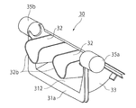
- FIG. 4 is a diagram illustrating a front schematic structure (FIG. 4A) and a rear schematic structure (FIG. 4B) of the mix door in order to describe a warm air guide channel 32 included in the mix door illustrated in FIG. 2.
- FIG. 7 (a) shows the side surface schematic structure (FIG. 7 (a)) and bottom surface schematic structure (FIG.7 (b)) of the mix door in the modification of the mix door with which the vehicle air conditioning unit shown in FIG. 1 is provided.
- the vehicle air conditioning unit 10 includes a cold air flow path 11 through which air supplied from the blower B flows, a warm air flow path 12 connected to the cold air flow path 11, a mixing chamber 13, and a cold air flow path. 11, a cold air opening 111 interposed between the mixing chamber 13, a warm air opening 121 interposed between the warm air flow path 12 and the mixing chamber 13, and a mix door (mixing means) 30 disposed in the mixing chamber 13.
- the upper outlet channel (first outlet channel) 14 disposed downstream of the mixing chamber 13 and on the cold air opening 111 side, and also disposed downstream of the mixing chamber 13 and on the warm air opening 121 side.
- An evaporator N1 is disposed in the cold air flow path 11, and a heater core N2 is disposed in the warm air flow path 12.
- the upper blow-out flow path 14 is disposed above the cold air opening 111 so that cold air from the cold air opening 111 (cold air blown upward from the cold air opening 111) is warmer than the warm air from the warm air opening 121. It is easy to flow.
- the lower outlet flow path 15 is disposed closer to the warm air opening 121 than the cold air opening 111, so that warm air from the warm air opening 121 is more easily flown than cool air from the cold air opening 111. Yes.
- the mix door 30 is for adjusting the mixing ratio of warm air and cold air (for temperature tuning).
- the air distribution door 40 is for distributing the air-conditioning air mixed in the mixing chamber 13 to the upper outlet flow path 14 and the lower outlet flow path 15.
- the air distribution door 40 is for rectifying the air-conditioning air blown from the mixing chamber 13 and tuning the air distribution of the blown air amount of the upper blown air and the lower blown air.
- the differential vent door 50 rectifies the ventilation of the upper outlet flow passage 14 and adjusts the ratio of the respective blowout air amounts from the vent duct 21 and the defrost duct 22 disposed downstream of the upper outlet passage 14. is there.
- the mix door 30, the air distribution door 40, and the differential vent door 50 are all rotatable to rectify the air flow.
- the air supplied from the blower B to the cool air passage 11 is cooled by the evaporator N1 to become cool air, and a part of this cool air is introduced into the warm air passage 12, and the heater core It is heated by N2 and becomes warm.
- the upstream end of the warm air flow path 12 is connected to the cold air flow path 11 between the downstream of the evaporator N ⁇ b> 1 and the cold air opening 111.
- the air flowing through the warm air passage 12 rises in temperature and is dried.
- the cool air flowing into the mixing chamber 13 through the cool air opening 111 and the warm air flowing into the mixing chamber 13 through the warm air opening 121 are mixed at a predetermined ratio in the mixing chamber 13 to form air conditioning air.
- the air is rectified by the wind door 40 and flows into the upper blowout flow path 14 or the lower blowout flow path 15 and blown out from the upper blowout flow path 14 or blown out from the lower blowout flow path 15.
- the upper blown air blown from the upper blowout flow path 14 is blown through the upper duct 21 for cooling and heating, for example, from the center vent and the side vent, or blown through the defrost duct 22 for preventing fogging of the vehicle window.
- the lower blowing air blown out from the lower blowing passage 15 into the passenger compartment is blown out from, for example, a foot side duct, and is mainly used for heating the lower limbs.
- the evaporator N1 has a purpose of cooling air, and may be a cooling device that allows, for example, cold water to flow instead of the evaporator.
- the heater core N2 only needs to have a function of heating air. For example, a heater using hot water or a heater using Joule heat can be used.
- the mix door 30 includes a rotary shaft portion 35 a, 35 b, a movable wall portion 31 that rotates around the rotary shaft portions 35 a, 35 b, and a movable door portion.
- the warm air guide channel 32 disposed on the rotating shaft portions 35a and 35b side of the wall portion 31 and the two side walls disposed so as to intersect the rotating shaft portions 35a and 35b and having a substantially fan-shaped side view. Part 33.
- the rotating shaft portions 35a and 35b of the mix door 30 are supported by a rotating bearing portion (not shown) and are disposed downstream of the movable wall portion 31.
- the movable wall portion 31 includes the cold air opening portion 111 and the warm air opening portion 121. (Fig. 1).
- the mix door 30 When the mix door 30 is displaced so that the cold air opening 111 is substantially blocked by the movable wall 31, the mix door 30 is positioned at a cold air minimizing position that minimizes the opening area of the cold air opening 111.
- the opening area of the cold air opening 111 is a cross-sectional area of a communication path that connects the cold air flow path 11 and the mixing chamber 13.
- the opening area of the warm air opening portion 121 is the largest.
- the mix door 30 when the mix door 30 is displaced so as to substantially close the warm air opening 121 with the movable wall 31, the mix door 30 is positioned at the warm air minimizing position that minimizes the opening area of the warm air opening 121. At this time, the opening area of the cold air opening 111 is the largest.
- the mix door 30 by displacing the mix door 30 to the cool air minimizing position, the temperature of the air-conditioning air mixed and flowing down in the mixing chamber 13 can be maximized, and the mix door 30 is displaced to the warm air minimizing position. Thereby, the temperature of the air for an air conditioning which flows down from the mixing chamber 13 can be made the lowest.
- the movable wall part 31 has a wall part flow path 311a and a ventilation blocking part 311b on the upstream side wall surface 311 (FIG. 3B).
- the wall portion flow path 311 a is formed at the center portion in the width direction of the upstream side wall surface 311, and the ventilation blocking portions 311 b are formed on both side portions in the width direction of the upstream side wall surface 311.
- the width of the wall portion flow path 311a is, for example, substantially equal to the width of one ventilation blocking portion 311b, and thus is approximately one third of the width of the movable wall portion 31.
- the ventilation blocking portion 311b is a curved surface (convex surface) having an arc cross section centering on the rotation shaft portions 35a and 35b, and is in contact with, for example, an edge region between the cold air opening portion 111 and the warm air opening portion 121 to mix. Regardless of the displacement position of the door 30, ventilation between the cool air opening 111 and the warm air opening 121 is prevented.
- the wall channel 311a is for maintaining ventilation between the cool air opening 111 and the warm air opening 121 regardless of the displacement position of the mix door 30.
- the wall portion flow path 311a has, for example, a circular shape (convex curved surface), a straight line having a cross-sectional shape centered on the rotation shaft portions 35a and 35b and a convex surface similar to the air flow preventing portion 311b and having a smaller curvature than the air flow preventing portion 311b.
- the shape of the wall channel 311a is not limited to the above shape as long as the ventilation between the cool air opening 111 and the warm air opening 121 is maintained.
- downstream side wall surface 312 of the movable wall portion 31 forms a curved surface or a flat surface with few steps between the side wall portions 33.
- the mix door 30 includes a cold air side door end portion 31 a at the cold air opening 111 side end portion of the movable wall portion 31, and a warm air opening portion of the movable wall portion 31.
- the warm side door end 31b may be provided at the 121 side end. Further, the cold air side door end portion 31 a and the warm air side door end portion 31 b may further be formed continuously with the side wall portion 33.
- the mix door 30 can more reliably close the cool air opening 111 at the cool air minimizing position and the warm air opening 121 at the cool air minimizing position by the cold air door end 31a and the warm air door end 31b. Can be closed more reliably.
- the warm air guide channel 32 has a substantially U-shaped cross section as shown in FIGS. 2 and 4B, and is disposed on the downstream side wall surface 312 side of the movable wall portion 31.
- the warm air guide channel 32 has a substantially U-shaped bottom 32c disposed on the movable wall 31 side and is open on the downstream side.
- the warm air guide upstream end 32 a of the warm air guide channel 32 is disposed on the warm air opening 121 side of the movable wall 31, and the warm air guide downstream end 32 b is disposed on the cold air opening 111 side of the movable wall portion 31.
- the downstream end 32b is farther from the movable wall portion 31 than the warm air guide upstream end 32a. Further, the warm air guide downstream end 32b is disposed downstream of the warm air guide upstream end 32a.
- the warm air guide channel 32 guides the warm air flowing from the warm air channel 12 to the mixing chamber 13 and reaching the warm air guide upstream end 32a to the warm air guide downstream end 32b, and from the cool air channel 11 to the mixing chamber. 13 can be mixed with the cold air flowing into the air.
- the shape or the like of the warm air guide channel 32 is not limited to the above shape as long as the warm air that has reached the warm air guide upstream end 32a is mixed with the cold air that has flowed into the mixing chamber 13.
- the mix door 30 has an opening ratio of the cold air opening 111 (the opening area of the cold air opening 111 at the cold air maximizing position (warm air minimizing position) of the opening area of the cold air opening 111 at the position of FIG. 5).
- the ratio of the area is 50% or less, while the opening ratio of the warm air opening 121 is approximately 50% or more (warm air flows into the mixing chamber 13 more than cool air).
- the cold air flow 112 (solid arrow in FIG. 6) flowing through the cold air flow path 11 passes through the cold air opening 111 and flows into the mixing chamber 13 as shown in FIG. Then, the flow is divided into a bypass cold airflow 112b that passes through the wall channel 311a of the movable wall 31 and flows to the warm air opening 121 side.
- the main cold air flow 112a expands in the vicinity of the mix door 30, so that the main mixed cold air flow 112c flows in the vicinity of the mix door 30 toward the upper outlet flow passage 14. And the sub-mixed cold airflow 112d that flows along the downstream side wall surface 312 (see FIGS. 2 and 4A) of the movable wall portion 31.
- the warm air flow 113 (broken arrow in FIG. 6) flowing through the warm air flow path 12 expands in the vicinity of the mix door 30 immediately after passing through the warm air opening 121.
- the main mixed warm airflow 113a that flows toward the flow path 15 and the sub-mixed warm airflow 113b that is guided to the warm air guide flow path 32 and flows toward the main mixed cold airflow 112c are divided.
- the main mixed cold airflow 112 c and the main mixed warm airflow 113 a can be mixed downstream of the mix door 30. Further, the sub-mixed cold airflow 112d flows along the downstream side wall surface 312 of the movable wall portion 31 and then mixes with the main mixed warm airflow 113a, whereby the main mixed warm airflow 113a can be cooled.
- the submixed cold airflow 112d and the submixed warm airflow 113b flow in the crossing / collision direction.
- the submixed warm air flow 113b is guided to the warm air guide channel 32 and flows therethrough, collision with the submixed cool airflow 112d is substantially avoided. That is, the submixed cold airflow 112d and the submixed warm airflow 113b can intersect without colliding with each other.
- the submixed warm airflow 113b can be mixed with the main mixed cold airflow 112c flowing toward the upper outlet flow passage 14, and the submixed cold airflow can be mixed with the main mixed warm airflow 113a flowing toward the lower outlet flow passage 15.
- the air flow 112d can be mixed.
- the temperature difference between the two can be set to an appropriate temperature difference.
- the bypass cold air flow 112b is mixed with the warm air flow 113, and the temperature difference between the cold air flow 112 and the warm air flow 113 is alleviated.
- the temperature difference of the air-conditioning air blown from 15 can be set to a more appropriate temperature difference.
- the mixing of the cool air and the warm air in the mixing chamber 13 and the vicinity thereof is performed by the mixing of the main mixed cold air flow 112c and the main mixed warm air flow 113a (mixing 1), which is generally performed in a rotary type mix door.
- mixing (mixing 3) for guiding the bypass cold airflow 112b to the warm airflow 113 by the wall channel 311a, and the warm air guiding flow
- mixing (mixing 4) that guides the sub-mixed warm air flow 113b to the main mixed cold air flow 112c through the path 32. Since the mixing 3 and the mixing 4 are bidirectional, the temperature difference between the upper blowing air and the lower blowing air should be rationally adjusted as compared with the unidirectional mixing in which the cold air is mixed to the warm air side. Can do.
- the opening ratio of the cold air opening 111 is increased, that is, if the opening ratio of the warm air opening 121 is decreased, the air-conditioning air flowing toward the upper blowing flow path 14 and the lower blowing flow path 15 is reduced. The temperature drops.
- the opening ratio of the cold air opening 111 is reduced, that is, if the opening ratio of the warm air opening 121 is increased, the temperature of the air-conditioning air flowing toward the upper blowing flow path 14 and the lower blowing flow path 15 is increased. rises.
- temperature tuning can be performed, and the temperature difference between the air-conditioning air blown from both the blow-out flow paths can be set to an appropriate temperature difference.
- the temperature change of the air-conditioning air with respect to the change in the opening ratio of 111 is not an essential requirement (or a decisive requirement). That is, appropriate temperature tuning can be easily performed.
- the air distribution door 40 disposed downstream of the mix door 30 rectifies the air-conditioning air mixed in the mixing chamber 13, thereby increasing or decreasing the flow rate of the air-conditioning air toward the upper outlet flow path 14. At the same time, the flow rate of the air-conditioning air toward the lower outlet passage 15 can be reduced or increased. In other words, the air distribution tuning can be performed by the air distribution door 40.
- the upper outlet flow path 14 is disposed above the cold air opening 111 so that the cold air from the cold air opening 111 flows more easily than the warm air from the warm air opening 121.
- the lower blow-off flow path 15 is disposed closer to the warm air opening 121 than the cold air opening 111, so that the warm air from the warm air opening 121 can flow more easily than the cold air from the cold air opening 111. Yes.
- the temperature tuning is performed by the displacement of the mix door 30, and the air distribution tuning is performed by the air distribution door 40. Therefore, mutual interference between the temperature tuning and the air distribution tuning can be prevented, and thus the temperature is adjusted. Tuning and air distribution tuning are both easy, and a comfortable head cold foot heat situation can be realized.
- the flow width of the bypass cold airflow 112b is defined by the width of the wall portion flow passage 311a.
- the ventilation resistance to the bypass cold airflow 112b flowing to the warm air opening 121 side along the wall channel 311a depends on the width of the wall channel 311a, the shape of the curved surface, etc.
- the ventilation resistance can be determined by appropriately setting the shape.
- the air for air conditioning is rectified by the air distribution door 40 and flows into the upper blowout flow path 14 and the lower blowout flow path 15.
- the temperature difference between the upper blown air blown from the center vent and the side vent or blown from the defrost to prevent fogging of the vehicle window and the lower blown air blown from the foot side duct is minimal or substantially zero. It becomes.
- the temperatures of the upper and lower blowing airs are the highest, and only the air distribution tuning of the upper and lower blowing air is performed.
- the mixing of the cool air and the warm air when the mix door 30 is in the warm air minimizing position will be described.
- the warm air flow 113 flowing through the warm air flow path 12 is blocked by the movable wall portion 31, and only the cold air flow 112 flows into the mixing chamber 13. Therefore, at this time, the temperature of the air-conditioning air is the lowest.
- the air for air conditioning is rectified by the air distribution door 40 and flows into the upper blowout flow path 14 and the lower blowout flow path 15.
- the temperature difference between the upper blown air blown from the center vent and the side vent, or blown from the defrost to prevent fogging of the vehicle window, and the lower blown air blown from the foot duct is also minimal or substantially zero in this case. It becomes.
- the temperatures of the upper and lower blowing airs are the lowest, and only the air distribution tuning of the substantially upper blowing air and the lower blowing air is performed.
- the side wall 33 has a wall channel 331a (not shown) on its outer wall surface 331, and the outer wall surface 331 itself has a rotation shaft 35a, It can be inclined with respect to the axis 35b, and the space between the cold air door end 31a and the warm air door end 31b can be recessed (FIGS. 7A and 7B). .
- the warm air guide passage 32 is disposed between the ventilation block 311b and the rotary shafts 35a and 35b. As described above, the warm air guide passage 32 guides the warm air flowing from the warm air flow path 12 to the mixing chamber 13 and reaching the warm air guide upstream end 32a to the warm air guide downstream end 32b.
- the warm air guide upstream end 32a is located on the rotation shafts 35a, 35b side of the ventilation block 311b, the warm air reaching the warm air guide upstream end 32a is not changed even if the position of the mix door 30 is displaced. It is difficult to be influenced by the bypass cold airflow 112b passing through the path 311a, and therefore high temperature air can be stably guided to the warm air guide passage 32.
- the vehicle air-conditioning unit 10 has an appropriate temperature difference between the upper blowing air and the lower blowing air in order to realize appropriate temperature tuning and air distribution tuning and to realize a comfortable head cold foot heat situation.
- the degree of mixing of the upper blown air and the lower blown air in the vehicle width direction can be set appropriately, and further, the upper blown air can be warmed to achieve appropriate heating.
- vehicle air conditioning unit according to the present invention is not limited to those described in the above embodiments, and can be appropriately modified and implemented without changing the gist thereof.
- the vehicle air conditioning unit according to the present invention can be industrially manufactured and used, and can be sold commercially, the present invention has industrial value and is used industrially. It is an invention that can.
Landscapes
- Physics & Mathematics (AREA)
- Thermal Sciences (AREA)
- Engineering & Computer Science (AREA)
- Mechanical Engineering (AREA)
- Air-Conditioning For Vehicles (AREA)
Abstract
容易な温度および配風チューニングと快適な頭寒足熱が可能な車両用空調ユニットを実現する。冷気流路11、暖気流路12、冷気と暖気とを混合する混合室13、混合室13に配設された混合手段30、混合室13の下流に配設された第1および第2の吹出流路14、15を備え、冷気流路11と混合室13が冷気開口部111で連通し、暖気流路12と混合室13が暖気開口部121で連通し、混合手段30は、冷気開口部111と暖気開口部121の開口面積を調整する可動壁部31、暖気の一部を第1の吹出流路14に導く暖気案内流路32、可動壁部31に形成されて冷気開口部111と暖気開口部121との間を通気する壁部流路311aを有し、冷気最小化位置と暖気最小化位置との間を変位可能とする。
Description
本発明は、車両における冷暖房などを行うための車両用空調ユニットに関するものである。
車両用空調ユニットは、エバポレータによって冷却された冷気と、ヒータコアによって加熱された暖気とを混合して空調用空気とし、この空調用空気を車室に吹出すことで、搭乗者に快適な冷暖房を提供し、またフロントガラスなどの曇り止めのための除湿を行う。ここで、冷房は空調用空気における冷気混合比率を高めることで行われ、暖房は同暖気混合比率を高めることで行われる。また除湿は、エバポレータによって冷却された冷気をヒータコアによって加熱して湿度を低くした空調用空気によって行われる。
冷暖房のために、車両用空調ユニットからセンタベント吹出口を経て車室に吹き出された空気(上方吹出空気)は、搭乗者の、主に上半身や頭部を暖めるなどし、フット吹出口を経て車室に吹き出された空気(下方吹出空気)は、搭乗者の主に足を暖めるなどする。したがって、搭乗者に快適な暖房である、いわゆる頭寒足熱状況を実現するためには、上方吹出空気と下方吹出空気との温度差を適切に設定する温度チューニングと、両吹出空気の熱量差などを適切なものとするために、両吹出空気の吹出風量を適切に設定する配風チューニングが必要となる。因みに、フロントガラスの曇り止めは、デフロスト吹出口を経て車室に吹き出された空気(上方吹出空気)によって行われる。
しかし、車両の小型化、快適な居住性を確保するための車室スペースの拡張、および車両の高機能化にともなう搭載機器の増加などのために、車両用空調ユニットの小型化が求められた結果、温度チューニングおよび配風チューニングを実現するための、冷気と暖気との混合室のスペースなどに制約が生じた。こうした制約は、温度チューニングを必須的要素(もしくは決定的要素)にしやすいことを否めない。
そこで、車両用空気調和装置(車両用空調ユニット)において、暖気と冷気とを混合して、上方の吹出口に送るか下方の吹出口に送るかの配風を行うロータリダンパ(配風調整ダンパ)に、暖気を上方の吹出口に向けて流すための案内通路を設けるとする技術思想がある(特許文献1)。この案内通路は、案内通路がないと下方の吹出口に流れてしまう暖気の一部を上方の吹出口に向けて流すことで、上方吹出空気と下方吹出空気との温度差を少なくすることができ(すなわち、温度チューニングが必須的要素(もしくは決定的要素)でなくなり)、快適な頭寒足熱状況が実現されるとされている。
また、暖気と冷気との混合比率を調整する混合フラップの周面の一部に凹部を設けた自動車用の暖房/空調装置(車両用空調ユニット)に係る技術思想がある(特許文献2)。当該技術思想によれば、エバポレータからの冷気の一部が混合フラップの凹部を通ってフット吹出口へ行く空調空気(下方吹出空気)の温度を適切に下げることができ(すなわち、下肢の温まり過ぎを防ぐことができ)、快適な頭寒足熱状況を実現できるとされている。
また、暖気と冷気とを混合するドラム型の混合ドアの周面の少なくとも1つの領域が、混合ドアの回転軸と同軸(ドラムの周面形状)に配置されるとともに、回転軸に向かって湾曲した(換言すれば、周面形状に対し逆反りした)少なくとも1つの領域を有する自動車用空調装置(車両用空調ユニット)に係る技術思想がある(特許文献3)。
当該技術思想によれば、周面形状領域では、その内面(周面と回転軸との間の領域)で暖気が上方に配風され、またその外面で冷気が上方に配風される結果、暖気と冷気とが混合されて上方吹出空気となる。一方、逆反り領域では、上方および下方への冷気の配風が行われ、逆反り領域の外面によって下方に配風された冷気が暖気と混合して下方吹出空気となる。その結果、上方吹出空気と下方吹出空気とを適切に混合することができ、頭寒足熱状況を実現できるとされている。
しかし、特許文献1が開示する技術思想では、案内通路を持ったロータリダンパの角度調整という、1つの調整項目によって、温度および配風の2項目のチューニングを行わねばならず、上方吹出空気および下方吹出空気の温度差のチューニングが必須的要件(もしくは決定的要件)となることが否めない。
また、特許文献2が開示する技術思想では、エバポレータからの冷気を暖気側に混合する一方、ヒータコアからの暖気を冷気側に混合しないため、改善の余地がある。
また、特許文献3が開示する技術思想では、周面形状領域と逆反り領域とが混合ドアの幅方向(ドアの回転軸の軸方向)で必然的に異なる領域に存在するため、混合ドアの幅方向で、上下方向の配風が異なってしまう。そのため、車幅方向において、上方吹出空気と下方吹出空気との混合度合が異なって、車幅両側部領域において、適切な頭寒足熱状況を実現できるとはいえない。たとえば、車幅中央領域で快適な頭寒足熱状況を実現するように暖気及び冷気の配風量を設定した場合、運転席および助手席においては車幅中央領域よりも上方吹出空気、下方吹出空気ともに温度が高くなり、快適な頭寒足熱の実現が困難となる。換言すれば、車幅方向で温度チューニングが変わってしまう。
そこで本発明は、温度チューニングおよび配風チューニングを容易にすることができ、上方吹出空気および下方吹出空気の温度差を適切なものとすることで、快適な頭寒足熱状況を実現することを課題とする。また車幅方向における上方吹出空気と下方吹出空気との混合度合を適切なものとすることも課題とする。さらに上方の吹出口及び下方の吹出口の両方から吹き出す吹出しモードのときに上方吹出空気を暖めることができる車両用空調ユニットの実現を課題とする。
上記課題を解決するため本発明にかかる車両用空調ユニットは、空気を冷却するための冷却手段を冷気流路に配設することができるとともに、空気を加熱するための加熱手段を暖気流路に配設することができ、冷気流路および暖気流路の下流に配設された混合室に、冷気開口部から冷気を流入させ、また暖気開口部から暖気を流入させ、混合室において冷気と暖気とを混合手段によって混合したうえで、混合室の下流に配設された第1の吹出流路および第2の吹出流路へと供給する。
混合手段は、冷気開口部を可動壁部で遮って冷気の流入量を最小化する冷気最小化位置と、暖気開口部を可動壁部で遮って暖気の流入量を最小化する暖気最小化位置との間を変位することができる。したがって、混合手段を変位させることで、混合室に流入する冷気および暖気の流量を変えて、第1の吹出流路および第2の吹出流路へと供給される空気の温度を調整することができる。
ここで混合手段は、冷気開口部および暖気開口部の開口面積を調整するための可動壁部と、暖気流路から流入した暖気の一部を第1の吹出流路に向けて導くための暖気案内流路と、冷気開口部と暖気開口部との間の通気を維持するために可動壁部に設けられた壁部流路とを有している。
暖気案内流路によって第1の吹出流路へと導かれる暖気は、混合手段の変位による影響を受けにくい。すなわち、混合手段の変位に対する第1の吹出流路に流入する暖気の流量変化が緩和される。第1の吹出流路へ流入しなかった暖気は第2の吹出流路に流入するから、混合手段の変位に対する第2の吹出流路に流入する暖気の流量変化も同様に緩和される。また暖気案内流路は、混合室において第1の吹出流路へと向かう冷気側に暖気を導入するから、該車両用空調ユニットから吹き出される上方吹出空気が暖められる。
したがって、第1の吹出流路に流入する暖気と第2の吹出流路に流入する暖気との流量差が大きくなりすぎること(温度差が大きくなりすぎること)を防いで、快適な頭寒足熱の暖房、およびクリティカルではない温度チューニング(適切な温度チューニング)が可能となり、加えて暖房能力が向上する。
壁部流路は、冷気開口部側から暖気開口部側へと冷気を流入させて、暖気開口部から混合室へと流入する暖気の温度を適切に低下させ、第1の吹出流路に流入する空気と第2の吹出流路に流入する空気との間の温度差が大きくなりすぎることを防ぐことができる(頭寒足熱をさらに快適にし、温度チューニングをさらに容易にする。)。
こうした温度チューニングは、配風チューニングとは別個のものであるから、配風チューニングと干渉しない。すなわち該車両用空調ユニットでは、適切な温度チューニングおよび適切な配風チューニングが実現される。
また暖気案内流路と壁部流路とは混合ドアの幅方向(ドアの回転軸の軸方向)で、必ずしも異なる領域に存在するものではないので、車幅方向における上方吹出空気と下方吹出空気との混合度合を適切に設定することができる。
このように該車両用空調ユニットは、適切な温度チューニングおよび配風チューニングを実現するとともに、第1の吹出流路が吹出す空気(上方吹出空気)と第2の吹出流路が吹出す空気(下方吹出空気)との間の温度差を適切な温度差として快適な頭寒足熱を実現することができ、上方吹出空気を暖めることができ、車幅方向における上方吹出空気と下方吹出空気との混合度合を適切に設定することができる(請求項1)。
混合室に配設された混合手段は回転軸部を有しており、混合手段の可動壁部は回転軸部を中心として回転し、回転軸部は可動壁部よりも下流に配設される(請求項2)。可動壁部は、冷気開口部側と暖気開口部側との間の通気のための壁部流路に加えて、冷気開口部側と暖気開口部側との間の通気を阻止するための通気阻止部を有している(請求項3)。
すなわち混合手段の可動壁部は、冷気開口部および暖気開口部の下流に配設された回転軸部を中心として回転することで、冷気開口部および暖気開口部の開口面積を調整するとともに、冷気開口部側と暖気開口部側との間の通気を、壁部流路によって確保して、冷気開口部側から暖気開口部側へと冷気を通流させることができる。ここで、壁部流路を通流する冷気の流量は、壁部流路の形状などで規定され、また通気阻止部によっても規定される。
通気阻止部が回転軸部を中心とした断面円弧形状の曲面であれば、混合手段の位置が変位(回転)しても、冷気開口部および暖気開口部の間の通気を阻止することができる。また壁部流路が、通気阻止部よりも曲率の小さな曲面、平面、回転軸部に向かって凸な曲面のうちの何れかであれば、混合手段の位置が変位(回転)しても冷気開口部および暖気開口部の間の通気を維持することができる(請求項4)。
暖気案内流路が暖気案内上流端と暖気案内下流端とを有し、暖気案内上流端が可動壁部の暖気開口部側に配設され、暖気案内下流端が可動壁部の冷気開口部側に配設されていれば、暖気案内流路は、暖気開口部から混合室に流入した暖気の一部を冷気開口部から混合室に流入した冷気に混合することができる(請求項5)。
暖気案内流路は、たとえば略U字形状の断面形状を有し、略U字形状の底部は混合手段の可動壁部に配設されるものであり(請求項6)、暖気案内流路は、たとえば通気阻止部よりも回転軸部の側に配設されるものである(請求項7)。
該車両用空調ユニットは、混合室から第1の吹出流路へ流入する空気の量と、第2の吹出流路へ流入する空気の量との配分を調整する配分調整手段を、さらに有するものであってもよい(請求項8)。そうすれば第1の吹出流路へ流入する空気の量と、第2の吹出流路へ流入する空気の量との配分を円滑にすることができる(配風チューニングをより容易なものとすることができる。)。
該車両用空調ユニットは、第1の吹出流路を通流する空気の温度が、第2の吹出流路を通流する空気の温度より低くするものであれば、搭乗者にとって快適な空調(頭寒足熱)を実現することができる(請求項9)。
また、該車両用空調ユニットでは、第1の吹出流路を通流した空気をデフロスト吹出口、センタベント吹出口およびサイドベント吹出口の少なくとも何れか1つの吹出口に供給することで(請求項10)、そして第2の吹出流路を通流した空気をフット吹出口に向けて供給することで(請求項11)、車内を快適に冷暖房することができ、また適切な除湿を実現することができる。
以上説明したように本発明にかかる車両用空調ユニットは、適切な温度チューニングおよび配風チューニングを実現し、また快適な頭寒足熱の暖房を実現するために、上方吹出空気および下方吹出空気の温度差を適切なものとするとともに、車幅方向における上方吹出空気と下方吹出空気との混合度合を適切に設定することができ、さらに上方吹出空気を暖めて適切な暖房を実現することができる。
以下、図面を参照して、本発明にかかる車両用空調ユニットについて説明する。
<車両用空調ユニット>
図1に示すように車両用空調ユニット10は、送風器Bから供給された空気が通流する冷気流路11、冷気流路11に接続された暖気流路12、混合室13、冷気流路11と混合室13との間に介在する冷気開口部111、暖気流路12と混合室13との間に介在する暖気開口部121、混合室13に配設されたミックスドア(混合手段)30、混合室13の下流でかつ冷気開口部111側に配設された上部吹出流路(第1の吹出流路)14、同じく混合室13の下流でかつ暖気開口部121側に配設された下部吹出流路(第2の吹出流路)15、ミックスドア30の下流に配設された配風ドア(配分調整手段)40、および上部吹出流路14の下流に配設されたデフベントドア50を有している。そして、冷気流路11にはエバポレータN1が配設されており、暖気流路12にはヒータコアN2が配設されている。
図1に示すように車両用空調ユニット10は、送風器Bから供給された空気が通流する冷気流路11、冷気流路11に接続された暖気流路12、混合室13、冷気流路11と混合室13との間に介在する冷気開口部111、暖気流路12と混合室13との間に介在する暖気開口部121、混合室13に配設されたミックスドア(混合手段)30、混合室13の下流でかつ冷気開口部111側に配設された上部吹出流路(第1の吹出流路)14、同じく混合室13の下流でかつ暖気開口部121側に配設された下部吹出流路(第2の吹出流路)15、ミックスドア30の下流に配設された配風ドア(配分調整手段)40、および上部吹出流路14の下流に配設されたデフベントドア50を有している。そして、冷気流路11にはエバポレータN1が配設されており、暖気流路12にはヒータコアN2が配設されている。
上部吹出流路14は、冷気開口部111の上方に配設されて、暖気開口部121からの暖気よりも冷気開口部111からの冷気(冷気開口部111から上方に向けて吹出す冷気)が通流しやすくなっている。一方、下部吹出流路15は、冷気開口部111よりも暖気開口部121に近いところに配設されて、冷気開口部111からの冷気よりも暖気開口部121からの暖気が通流しやすくなっている。
ここでミックスドア30は、暖気と冷気との混合比率を調整するため(温度チューニングをするため)のものである。また配風ドア40は、混合室13で混合された空調用空気を、上部吹出流路14と下部吹出流路15とに分配するためのものである。換言すれば、配風ドア40は、混合室13から吹出される空調用空気を整流して、上方吹出空気および下方吹出空気の吹出風量の配風チューニングをするためのものである。またデフベントドア50は、上部吹出流路14の通気を整流して、上部吹出流路14の下流に配設されたベントダクト21およびデフロストダクト22からの、それぞれの吹出風量の比率を調整するものである。ミックスドア30、配風ドア40およびデフベントドア50は何れも空気流を整流するために、回転可能になっている。
以上の構成を有する車両用空調ユニット10では、送風機Bから冷気流路11に供給された空気は、エバポレータN1によって冷却されて冷気となり、この冷気の一部が暖気流路12に導入され、ヒータコアN2によって加熱されて暖気となる。ここで、図1に示すように、暖気流路12の上流端は、エバポレータN1の下流と冷気開口部111との間において、冷気流路11に接続されている。暖気流路12を通流した空気は、温度が上昇して乾燥する。
冷気開口部111を経て混合室13に流入した冷気と、暖気開口部121を経て混合室13に流入した暖気とは、混合室13で所定の比率で混合されて空調用空気となって、配風ドア40で整流されて、上部吹出流路14、または下部吹出流路15へと流入し、上部吹出流路14から吹出され、あるいは下部吹出流路15から吹出される。ここで、上部吹出流路14から吹出される上方吹出空気は、冷暖房のため上部ダクト21を経て、たとえばセンタベントおよびサイドベントから吹出され、あるいは車窓の曇り止めのためデフロストダクト22を経て吹出される。一方、下部吹出流路15から車室に吹出される下方吹出空気は、たとえばフット側ダクトから吹出されて、搭乗者の主に下肢の暖房に供される。
なおエバポレータN1は、空気を冷却する目的を有するものであり、エバポレータに替えて、たとえば冷水などを通流させる冷却装置であってもよい。またヒータコアN2は、空気を加熱できる機能を有するものであればよく、たとえば温水によるヒータ、またはジュール熱を利用するヒータなどを用いることができる。
<ミックスドア(混合手段)>
図2、図3(a)および図3(b)に示すようにミックスドア30は、回転軸部35a、35bと、これら回転軸部35a、35bを中心として回転する可動壁部31と、可動壁部31よりも回転軸部35a、35b側に配設された暖気案内流路32と、回転軸部35a、35bと交わるように配設されて側面視形状が略扇形状をなす2つの側壁部33とを有している。
図2、図3(a)および図3(b)に示すようにミックスドア30は、回転軸部35a、35bと、これら回転軸部35a、35bを中心として回転する可動壁部31と、可動壁部31よりも回転軸部35a、35b側に配設された暖気案内流路32と、回転軸部35a、35bと交わるように配設されて側面視形状が略扇形状をなす2つの側壁部33とを有している。
ミックスドア30の回転軸部35a、35bは、図示しない回転軸受部に支持されて可動壁部31よりも下流に配設されており、可動壁部31は、冷気開口部111と暖気開口部121との間で回転可能となっている(図1)。
可動壁部31で冷気開口部111を略塞ぐようにミックスドア30を変位させると、ミックスドア30は、冷気開口部111の開口面積を最小化する冷気最小化位置に位置づけられる。ここで冷気開口部111の開口面積とは冷気流路11と混合室13とを連通する連通路の断面積である。可動壁部31が冷気最小化位置にあるときには、暖気開口部121の開口面積が最も広くなる。
同様に、可動壁部31で暖気開口部121を略塞ぐようにミックスドア30を変位させると、ミックスドア30は、暖気開口部121の開口面積を最小化する暖気最小化位置に位置づけられる。このときには、冷気開口部111の開口面積が最も広くなる。
したがって、ミックスドア30を冷気最小化位置に変位させることで、混合室13で混合されて流下する空調用空気の温度を最も高くすることができ、またミックスドア30を暖気最小化位置に変位させることで、混合室13から流下する空調用空気の温度を最も低くすることができる。
<可動壁部>
可動壁部31は、その上流側壁面311に壁部流路311aおよび通気阻止部311bを有している(図3(b))。壁部流路311aは、上流側壁面311の幅方向の中央部に形成されており、また通気阻止部311bは、上流側壁面311の幅方向の両側部側にそれぞれ形成されている。壁部流路311aの幅は、たとえば1つの通気阻止部311bの幅に略等しく、したがって可動壁部31の幅の略三分の一となっている。
可動壁部31は、その上流側壁面311に壁部流路311aおよび通気阻止部311bを有している(図3(b))。壁部流路311aは、上流側壁面311の幅方向の中央部に形成されており、また通気阻止部311bは、上流側壁面311の幅方向の両側部側にそれぞれ形成されている。壁部流路311aの幅は、たとえば1つの通気阻止部311bの幅に略等しく、したがって可動壁部31の幅の略三分の一となっている。
通気阻止部311bは、回転軸部35a、35bを中心とする断面円弧形状の曲面(凸面)であって、たとえば冷気開口部111と暖気開口部121との間の縁部領域に接して、ミックスドア30の変位位置にかかわらず、冷気開口部111と暖気開口部121との間の通気を阻止する。
一方、壁部流路311aは、ミックスドア30の変位位置にかかわらず、冷気開口部111と暖気開口部121との間の通気を維持するためのものである。壁部流路311aは、たとえば回転軸部35a、35bを中心とする断面形状が、通気阻止部311bと同様の凸面で通気阻止部311bよりも曲率が小さい円弧形状(凸の曲面)、直線をなす面(平面)、または通気阻止部311bと逆の曲率を有する面(凹の曲面)、あるいはこれらを組み合わせた形状で構成される。
したがって壁部流路311aと通気阻止部311bとの間には段差が生じる。もちろん壁部流路311aの形状は、冷気開口部111と暖気開口部121との間の通気を維持するものであれば上記の形状に限定されない。
一方、可動壁部31の下流側壁面312は、両側壁部33の間において、段差の少ない曲面または平面をなしている。
ミックスドア30は、図3(a)および図3(b)に示すように、可動壁部31の冷気開口部111側端部に冷気側ドア端部31aを、可動壁部31の暖気開口部121側端部に暖気側ドア端部31bを有していてもよい。また、これら冷気側ドア端部31aおよび暖気側ドア端部31bは、さらに側壁部33に連続して形成されていてもよい。
これら冷気側ドア端部31aおよび暖気側ドア端部31bによって、ミックスドア30は、冷気最小化位置において冷気開口部111をより確実に閉塞することができ、また暖気最小化位置において暖気開口部121をより確実に閉塞することができる。
<暖気案内流路>
暖気案内流路32は、図2および図4(b)に示すように略U字形状の断面形状を有し、可動壁部31の下流側壁面312側に配設されている。暖気案内流路32は、略U字形状の底部32cが可動壁部31側に配設され、下流側が開口している。
暖気案内流路32は、図2および図4(b)に示すように略U字形状の断面形状を有し、可動壁部31の下流側壁面312側に配設されている。暖気案内流路32は、略U字形状の底部32cが可動壁部31側に配設され、下流側が開口している。
暖気案内流路32の暖気案内上流端32aは可動壁部31の暖気開口部121側に配設され、暖気案内下流端32bは可動壁部31の冷気開口部111側に配設され、暖気案内下流端32bは、暖気案内上流端32aよりも可動壁部31から離間している。また、暖気案内下流端32bは暖気案内上流端32aよりも下流に配設されている。
したがって、暖気案内流路32は、暖気流路12から混合室13へと流入し暖気案内上流端32aへと到達した暖気を、暖気案内下流端32bへと導いて、冷気流路11から混合室13へと流入した冷気に混合することができる。暖気案内流路32の形状等は、暖気案内上流端32aに到達した暖気を混合室13へと流入した冷気に混合するものであれば上記の形状等に限定されない。
<混合室における冷気と暖気との混合>
次に、混合室13における冷気と暖気との混合などについて説明する。先ず、ミックスドア30が冷気最小化位置と暖気最小化位置との間にある場合における冷気と暖気との混合などについて説明する。
次に、混合室13における冷気と暖気との混合などについて説明する。先ず、ミックスドア30が冷気最小化位置と暖気最小化位置との間にある場合における冷気と暖気との混合などについて説明する。
図5では、ミックスドア30は、冷気開口部111の開口率(図5の位置にある冷気開口部111の開口面積の、冷気最大化位置(暖気最小化位置)にある冷気開口部111の開口面積に対する比率)が50パーセント以下である一方、暖気開口部121の開口率が概ね50パーセント若しくはそれ以上となっている(暖気が冷気よりも多く混合室13に流入する。)。
このとき、冷気流路11を通流する冷気流112(図6の実線矢印)は、図6に示すように、冷気開口部111を通過して混合室13へと流入する主冷気流112aと、可動壁部31の壁部流路311aを通過して暖気開口部121側へと通流するバイパス冷気流112bとに分流される。
主冷気流112aは、冷気開口部111を通過直後、ミックスドア30の近傍において流路が拡がるために、ミックスドア30の近傍を上部吹出流路14の方向に向け通流する主混合冷気流112cと、可動壁部31の下流側壁面312(図2および図4(a)参照)に沿うようにして通流する副混合冷気流112dとに分流される。
一方、暖気流路12を通流する暖気流113(図6の破線矢印)は、暖気開口部121を通過直後、ミックスドア30の近傍において流路が拡がるため、ミックスドア30の近傍を下部吹出流路15に向け通流する主混合暖気流113aと、暖気案内流路32に導かれて主混合冷気流112cに向け通流する副混合暖気流113bとに分流される。
主混合冷気流112cと主混合暖気流113aとは、ミックスドア30の下流で混合することができる。また副混合冷気流112dは、可動壁部31の下流側壁面312に沿うようにして通流したのち主混合暖気流113aと混合することで、主混合暖気流113aを冷やすことができる。
さて、ミックスドア30の可動壁部31の下流側において、副混合冷気流112dおよび副混合暖気流113bは、交差・衝突する方向に通流する。しかし、副混合暖気流113bは、暖気案内流路32に導かれて通流するため、副混合冷気流112dとの衝突が略回避される。すなわち、副混合冷気流112dおよび副混合暖気流113bは、互いに衝突せず交差することができる。こうして、上部吹出流路14に向け通流する主混合冷気流112cに副混合暖気流113bを混合することができ、また下部吹出流路15に向け通流する主混合暖気流113aに副混合冷気流112dを混合することができる。
したがって、上部吹出流路14および下部吹出流路15から吹出される空調用空気の温度差が大きくなることを防ぐことができる。換言すれば、両者の温度差を適切な温度差とすることができる。また暖気開口部121近傍において、バイパス冷気流112bが暖気流113と混合して、冷気流112と暖気流113との間の温度差が緩和されるから、上部吹出流路14および下部吹出流路15から吹出される空調用空気の温度差を、より適切な温度差とすることができる。
このように、混合室13およびその近傍における冷気と暖気との混合は、ロータリー式ミックスドアで一般的に行われている主混合冷気流112cと主混合暖気流113aとの混合(混合1)と、主混合暖気流113aへの副混合冷気流112dの混合(混合2)との他に、壁部流路311aによってバイパス冷気流112bを暖気流113へ導く混合(混合3)と、暖気案内流路32によって副混合暖気流113bを主混合冷気流112cへ導く混合(混合4)とがある。そして、混合3と混合4とは双方向性のものだから、冷気を暖気側に混合するといった一方向性の混合とくらべ、上方吹出空気と下方吹出空気との温度差を合理的に調整することができる。
ここで、冷気開口部111の開口率を大きくすれば、すなわち、暖気開口部121の開口率を小さくすれば、上部吹出流路14および下部吹出流路15へ向けて通流する空調用空気の温度が低下する。一方、冷気開口部111の開口率を小さくすれば、すなわち、暖気開口部121の開口率を大きくすれば、上部吹出流路14および下部吹出流路15へ向けて通流する空調用空気の温度が上昇する。
このように、ミックスドア30を変位させることで、温度チューニングを行うことができ、両吹出流路から吹出される空調用空気の温度差を適切な温度差とすることができるため、冷気開口部111の開口率の変化(暖気開口部121の開口率の変化)に対する空調用空気の温度変化は必須的要件(もしくは決定的要件)ではない。すなわち適切な温度チューニングを容易に行うことができる。
ミックスドア30の下流に配設された配風ドア40は、混合室13で混合された空調用空気を整流することで、上部吹出流路14へと向かう空調用空気の流量を増加あるいは減少させるとともに、下部吹出流路15へと向かう空調用空気の流量を減少あるいは増加させることができる。すなわち、配風ドア40によって、配風チューニングを行うことができる。
ここで、上部吹出流路14は、冷気開口部111の上方に配設されて、暖気開口部121からの暖気よりも冷気開口部111からの冷気が通流しやすくなっている。また、下部吹出流路15は、冷気開口部111よりも暖気開口部121に近いところに配設されて、冷気開口部111からの冷気よりも暖気開口部121からの暖気が通流しやすくなっている。
上部吹出流路14への空調用空気の流量を増加させるときには、すなわち、下部吹出流路15への空調用空気の流量を減少させるときには、混合室13と上部吹出流路14との間の流路が拡大するように配風ドア40の位置を変位させる。一方、下部吹出流路15への空調用空気の流量を増加させるときには、混合室13と上部吹出流路14との間の流路を狭めるように配風ドア40の位置を変位させる。
このように、温度チューニングはミックスドア30の変位によって行われ、そして配風チューニングは配風ドア40によって行われるから、温度チューニングと配風チューニングとの相互干渉を防ぐことができ、これによって、温度チューニングおよび配風チューニングが双方とも容易となり、しかも快適な頭寒足熱状況を実現することができる。
なお、バイパス冷気流112bは、可動壁部31の通気阻止部311bを通流できないから、バイパス冷気流112bの流路幅は、壁部流路311aの幅によって規定される。壁部流路311aに沿って暖気開口部121側へと通流するバイパス冷気流112bに対する通気抵抗は、壁部流路311aの幅、曲面の形状等に依存するから、壁部流路311aの形状を適宜設定することで通気抵抗を定めることができる。
次に、ミックスドア30が冷気最小化位置にある場合における冷気と暖気との混合などについて説明する。この場合には、冷気流路11を流れる冷気流112は可動壁部31で阻止され、バイパス冷気流112bは暖気側ドア端部31bにより阻止されるので、混合室13に流入するのは、暖気流113のみとなる。したがってこのときには、空調用空気の温度は最も高くなる。
空調用空気は、配風ドア40で整流されて、上部吹出流路14および下部吹出流路15へと流入する。センタベントおよびサイドベントから吹出され、あるいは車窓の曇り止めのためデフロストから吹出される上方吹出空気と、フット側ダクトから吹出される下方吹出空気との温度差は、この場合には最小または略ゼロとなる。
すなわち、上方吹出空気および下方吹出空気の温度が何れも最も高くなり、上方吹出空気と下方吹出空気との配風チューニングのみを行うこととなる。
さらに、ミックスドア30が暖気最小化位置にある場合における冷気と暖気との混合などについて説明する。この場合には、暖気流路12を流れる暖気流113は可動壁部31で阻止され、混合室13に流入するのは、冷気流112のみとなる。したがってこのときには、空調用空気の温度は最も低くなる。
空調用空気は、配風ドア40で整流されて、上部吹出流路14および下部吹出流路15へと流入する。センタベントおよびサイドベントから吹出され、あるいは車窓の曇り止めのためデフロストから吹出される上方吹出空気と、フット側ダクトから吹出される下方吹出空気との温度差は、この場合にも最小または略ゼロとなる。
すなわち、上方吹出空気および下方吹出空気の温度が何れも最も低くなり、略上方吹出空気と下方吹出空気との配風チューニングのみを行うこととなる。
ミックスドア30の構成は上述したものに限定されない。例えば、別の実施形態においては、側壁部33は、その外側壁面331に(図示しない)壁部流路331aを有しており、壁部流路331aは、外側壁面331自体が回転軸35a、35bの軸線に対して傾斜しており、冷気用ドア端部31aと暖気用ドア端部31bとの間が窪んでいるものとすることができる(図7(a)、図7(b))。このような形状としたので、ミックスドア30が冷気最小化位置と暖気最小化位置との間にある場合には、冷気流路11を通流して混合室13へと流入する主冷気流112aと、側壁部33の壁部流路331aを通過して暖気開口部121側へと通流するバイパス冷気流112e(図示しない)とに分流される。そして、暖気流113へ導かれ、下方吹出空気を冷やすことができる。一般に、車両用空調ユニットのフット吹出口は、ユニットの左右端部に備えられることが多く、ミックスドア30の左右の側壁部33、33に壁部流路331a、331aを設けて暖気流113を冷やす機能を付加することは、下方吹出空気を冷やすうえで合理的である。
また、暖気案内通路32は、通気阻止部311bと回転軸35a、35bとの間に配置されていることが望ましい。前記したように、暖気案内通路32は暖気流路12から混合室13へと流入し暖気案内上流端32aへ到達した暖気を、暖気案内下流端32bへと導くものである。ここで、暖気案内上流端32aは通気阻止部311bの回転軸35a、35b側に位置するので、暖気案内上流端32aに到達する暖気流は、ミックスドア30の位置が変位しても壁部流路311aを通過するバイパス冷気流112bの影響を受けにくく、従って暖気案内通路32に温度の高い空気を安定的に導くことができる。
以上説明したとおり、車両用空調ユニット10は、適切な温度チューニングおよび配風チューニングを実現し、また快適な頭寒足熱の状況を実現するために、上方吹出空気および下方吹出空気の温度差を適切なものとするとともに、車幅方向における上方吹出空気と下方吹出空気との混合度合を適切に設定することができ、さらに上方吹出空気を暖めて適切な暖房を実現することができる。
なお本発明にかかる車両用空調ユニットは、上記各実施形態に記載されたものに限定されるものではなく、それらの趣旨を変更することなく、適宜変形して実施することができる。
本発明にかかる車両用空調ユニットは、工業的に製造および使用などすることができるから、また商業的に販売などすることができるから、本発明は経済的価値を有して産業上利用することができる発明である。
10 車両用空調ユニット
11 冷気流路
111 冷気開口部
12 暖気流路
121 暖気開口部
13 混合室
14 第1の吹出流路(上部吹出流路)
15 第2の吹出流路(下部吹出流路)
30 混合手段(ミックスドア)
31 可動壁部
311 可動壁部の上流側面
311a 可動壁部の壁部流路
311b 可動壁部の通気阻止部
312 可動壁部の下流側面
32 暖気案内流路
32a 暖気案内上流端
32b 暖気案内下流端
32c 暖気案内流路の底部
33 側壁部
331 側壁部の外側壁面
331a 側壁部の壁部流路
35a、35b 回転軸部
40 配分調整手段(配風ドア)
B 送風機
N1 冷却手段(エバポレータ)
N2 加熱手段(ヒータコア)
11 冷気流路
111 冷気開口部
12 暖気流路
121 暖気開口部
13 混合室
14 第1の吹出流路(上部吹出流路)
15 第2の吹出流路(下部吹出流路)
30 混合手段(ミックスドア)
31 可動壁部
311 可動壁部の上流側面
311a 可動壁部の壁部流路
311b 可動壁部の通気阻止部
312 可動壁部の下流側面
32 暖気案内流路
32a 暖気案内上流端
32b 暖気案内下流端
32c 暖気案内流路の底部
33 側壁部
331 側壁部の外側壁面
331a 側壁部の壁部流路
35a、35b 回転軸部
40 配分調整手段(配風ドア)
B 送風機
N1 冷却手段(エバポレータ)
N2 加熱手段(ヒータコア)
Claims (11)
- 冷気流路と、
暖気流路と、
前記冷気流路および前記暖気流路の下流に配設されて冷気と暖気とを混合する混合室と、
前記冷気流路と前記混合室とを連通する冷気開口部と、
前記暖気流路と前記混合室とを連通する暖気開口部と、
前記混合室の下流に配設された第1の吹出流路、第2の吹出流路と、
前記混合室に配設され、前記冷気開口部及び/もしくは前記暖気開口部の開口面積を調整する可動壁部、前記暖気流路からの暖気の一部を前記第1の吹出流路へと導くための暖気案内流路、前記可動壁部に設けられ前記冷気開口部と前記暖気開口部との間の通気を維持するための壁部流路、を有する混合手段であって、前記冷気開口部を前記可動壁部で遮って冷気流入を最小化する冷気最小化位置と、前記暖気開口部を前記可動壁部で遮って暖気流入を最小化する暖気最小化位置と、の間を変位することを可能とし、前記第1の吹出流路を通流する空気と前記第2の吹出流路を通流する空気との温度差を調整することを可能とする、混合手段と
を備える車両用空調ユニット。 - 前記混合手段は、回転軸部を有し、
前記可動壁部は、回転軸部を中心として回転し、
前記回転軸部が前記可動壁部よりも下流に配設された、
請求項1記載の車両用空調ユニット。 - 前記可動壁部は、その上流側面に、前記冷気開口部側と前記暖気開口部側との間の通気を阻止するための通気阻止部を、さらに有する、
請求項1記載の車両用空調ユニット。 - 前記通気阻止部は、前記回転軸部を中心とした断面円弧形状の曲面であり、
前記壁部流路は、前記通気阻止部よりも曲率の小さな曲面、平面、前記回転軸部に向かって凸な曲面、のうちいずれかである、請求項3記載の車両用空調ユニット。 - 前記暖気案内流路は、暖気案内上流端と暖気案内下流端とを有し、
前記暖気案内上流端は、前記可動壁部の前記暖気開口部側に配設され、
前記暖気案内下流端は、前記可動壁部の前記冷気開口部側に配設される、
請求項1乃至4のいずれかに記載の車両用空調ユニット。 - 前記暖気案内流路は、略U字形状の断面形状を有し、前記暖気案内流路の底部は前記混合手段の前記可動壁部に配設されている、請求項1乃至5のいずれかに記載の車両用空調ユニット。
- 前記暖気案内流路は、前記通気阻止部の前記回転軸部の側に配設されている、請求項1乃至6のいずれかに記載の車両用空調ユニット。
- 前記混合室から前記第1の吹出流路へ流入する空気の量と、前記第2の吹出流路へ流入する空気の量との配分を調整する配分調整手段をさらに有する、請求項1乃至7のいずれかに記載の車両用空調ユニット。
- 前記第1の吹出流路を通流する空気の温度が、前記第2の吹出流路を通流する空気の温度より低い、請求項1乃至8のいずれかに記載の車両用空調ユニット。
- 前記第1の吹出流路を通流した空気は、デフロスト吹出口、センタベント吹出口およびサイドベント吹出口の少なくとも何れか1つの吹出口に向け流れる、請求項1乃至9のいずれかに記載の車両用空調ユニット。
- 前記第2の吹出流路を通流した空気は、前記フット吹出口に向けて流れる、請求項1乃至10のいずれかに記載の車両用空調ユニット。
Applications Claiming Priority (2)
| Application Number | Priority Date | Filing Date | Title |
|---|---|---|---|
| JP2013-152359 | 2013-07-23 | ||
| JP2013152359A JP2016182835A (ja) | 2013-07-23 | 2013-07-23 | 車両用空調ユニット |
Publications (1)
| Publication Number | Publication Date |
|---|---|
| WO2015012286A1 true WO2015012286A1 (ja) | 2015-01-29 |
Family
ID=52393319
Family Applications (1)
| Application Number | Title | Priority Date | Filing Date |
|---|---|---|---|
| PCT/JP2014/069378 Ceased WO2015012286A1 (ja) | 2013-07-23 | 2014-07-23 | 車両用空調ユニット |
Country Status (2)
| Country | Link |
|---|---|
| JP (1) | JP2016182835A (ja) |
| WO (1) | WO2015012286A1 (ja) |
Cited By (5)
| Publication number | Priority date | Publication date | Assignee | Title |
|---|---|---|---|---|
| WO2016142115A1 (fr) * | 2015-03-10 | 2016-09-15 | Valeo Systemes Thermiques | Circuits de climatisation pour vehicule automobile |
| FR3091671A1 (fr) * | 2019-01-15 | 2020-07-17 | Valeo Systemes Thermiques | Dispositif de chauffage, ventilation et/ou climatisation |
| WO2021099523A1 (en) * | 2019-11-21 | 2021-05-27 | Valeo Klimasysteme Gmbh | Heating, ventilation and/or air conditioning unit for a car |
| CN113226810A (zh) * | 2018-12-21 | 2021-08-06 | 株式会社电装 | 车辆用空调装置 |
| WO2025233106A1 (de) | 2024-05-08 | 2025-11-13 | Klueber Lubrication München Gmbh & Co. Kg | Polyolester als basisöl für schmierstoffzusammensetzungen |
Families Citing this family (1)
| Publication number | Priority date | Publication date | Assignee | Title |
|---|---|---|---|---|
| US12479266B2 (en) | 2020-01-17 | 2025-11-25 | Hanon Systems | Air conditioner for vehicle |
Citations (7)
| Publication number | Priority date | Publication date | Assignee | Title |
|---|---|---|---|---|
| JP2000203238A (ja) * | 1998-12-22 | 2000-07-25 | Valeo Climatisation | 自動車用の暖房/空調装置 |
| JP2005231511A (ja) * | 2004-02-19 | 2005-09-02 | Denso Corp | 車両用空調装置 |
| JP2006137295A (ja) * | 2004-11-12 | 2006-06-01 | Mitsubishi Heavy Ind Ltd | 車両用空気調和機 |
| JP2007506600A (ja) * | 2003-06-30 | 2007-03-22 | ベール ゲーエムベーハー ウント コー カーゲー | 自動車空調装置の空気案内ハウジング用ドア |
| JP2007519570A (ja) * | 2004-01-30 | 2007-07-19 | ベール アメリカ インコーポレイテッド | 換気装置用空気混合器 |
| JP2008094187A (ja) * | 2006-10-10 | 2008-04-24 | Denso Corp | 車両用空調装置 |
| JP2012183865A (ja) * | 2011-03-03 | 2012-09-27 | Japan Climate Systems Corp | 車両用空調装置 |
-
2013
- 2013-07-23 JP JP2013152359A patent/JP2016182835A/ja active Pending
-
2014
- 2014-07-23 WO PCT/JP2014/069378 patent/WO2015012286A1/ja not_active Ceased
Patent Citations (7)
| Publication number | Priority date | Publication date | Assignee | Title |
|---|---|---|---|---|
| JP2000203238A (ja) * | 1998-12-22 | 2000-07-25 | Valeo Climatisation | 自動車用の暖房/空調装置 |
| JP2007506600A (ja) * | 2003-06-30 | 2007-03-22 | ベール ゲーエムベーハー ウント コー カーゲー | 自動車空調装置の空気案内ハウジング用ドア |
| JP2007519570A (ja) * | 2004-01-30 | 2007-07-19 | ベール アメリカ インコーポレイテッド | 換気装置用空気混合器 |
| JP2005231511A (ja) * | 2004-02-19 | 2005-09-02 | Denso Corp | 車両用空調装置 |
| JP2006137295A (ja) * | 2004-11-12 | 2006-06-01 | Mitsubishi Heavy Ind Ltd | 車両用空気調和機 |
| JP2008094187A (ja) * | 2006-10-10 | 2008-04-24 | Denso Corp | 車両用空調装置 |
| JP2012183865A (ja) * | 2011-03-03 | 2012-09-27 | Japan Climate Systems Corp | 車両用空調装置 |
Cited By (9)
| Publication number | Priority date | Publication date | Assignee | Title |
|---|---|---|---|---|
| WO2016142115A1 (fr) * | 2015-03-10 | 2016-09-15 | Valeo Systemes Thermiques | Circuits de climatisation pour vehicule automobile |
| FR3033527A1 (fr) * | 2015-03-10 | 2016-09-16 | Valeo Systemes Thermiques | Circuits de climatisation pour vehicule automobile |
| CN113226810A (zh) * | 2018-12-21 | 2021-08-06 | 株式会社电装 | 车辆用空调装置 |
| CN113226810B (zh) * | 2018-12-21 | 2024-02-20 | 株式会社电装 | 车辆用空调装置 |
| FR3091671A1 (fr) * | 2019-01-15 | 2020-07-17 | Valeo Systemes Thermiques | Dispositif de chauffage, ventilation et/ou climatisation |
| EP3683075A1 (fr) * | 2019-01-15 | 2020-07-22 | Valeo Systemes Thermiques | Dispositif de chauffage, ventilation et/ou climatisation |
| WO2021099523A1 (en) * | 2019-11-21 | 2021-05-27 | Valeo Klimasysteme Gmbh | Heating, ventilation and/or air conditioning unit for a car |
| US12350995B2 (en) | 2019-11-21 | 2025-07-08 | Valeo Klimasysteme Gmbh | Heating, ventilation and/or air conditioning unit for a car |
| WO2025233106A1 (de) | 2024-05-08 | 2025-11-13 | Klueber Lubrication München Gmbh & Co. Kg | Polyolester als basisöl für schmierstoffzusammensetzungen |
Also Published As
| Publication number | Publication date |
|---|---|
| JP2016182835A (ja) | 2016-10-20 |
Similar Documents
| Publication | Publication Date | Title |
|---|---|---|
| JP5972736B2 (ja) | 車両用空気調和装置 | |
| JP5703002B2 (ja) | 車両用空気調和装置 | |
| WO2015012286A1 (ja) | 車両用空調ユニット | |
| JP6632505B2 (ja) | 車両用空調ユニット | |
| JP2017094753A (ja) | 車両用空調ユニット | |
| JP2007099188A (ja) | 車両用空調装置 | |
| CN104002636B (zh) | 车辆用空调装置 | |
| CN110678338A (zh) | 车用空调 | |
| EP3363665B1 (en) | Air conditioning device for vehicle | |
| US10232679B2 (en) | Air deflector device of an air conditioning system for an automobile | |
| WO2014058009A1 (ja) | 車両用空調装置 | |
| KR101648124B1 (ko) | 차량용 공조장치 | |
| JP2016055758A (ja) | 車両用空調装置 | |
| JP6269432B2 (ja) | 車両用空調装置 | |
| WO2006074125A1 (en) | Air control door with integrated stratification feature | |
| JP2018118523A (ja) | 車両用空調装置 | |
| JP2019209869A (ja) | 車両用空調装置 | |
| JP2006001378A (ja) | 車両用空調装置 | |
| JP6795896B2 (ja) | 車両用空調装置 | |
| JP6235271B2 (ja) | 車両用空調ユニット | |
| JP4111143B2 (ja) | 車両用空調装置 | |
| KR101238229B1 (ko) | 차량용 후석 공조장치 | |
| JP2005219574A (ja) | 車両用空調装置 | |
| JP6510916B2 (ja) | 車両用空調装置 | |
| CN114161895B (zh) | 一种汽车用空调装置 |
Legal Events
| Date | Code | Title | Description |
|---|---|---|---|
| 121 | Ep: the epo has been informed by wipo that ep was designated in this application |
Ref document number: 14830073 Country of ref document: EP Kind code of ref document: A1 |
|
| NENP | Non-entry into the national phase |
Ref country code: DE |
|
| 122 | Ep: pct application non-entry in european phase |
Ref document number: 14830073 Country of ref document: EP Kind code of ref document: A1 |
|
| NENP | Non-entry into the national phase |
Ref country code: JP |