WO2014208672A1 - 円筒型タンクの構築方法 - Google Patents
円筒型タンクの構築方法 Download PDFInfo
- Publication number
- WO2014208672A1 WO2014208672A1 PCT/JP2014/067010 JP2014067010W WO2014208672A1 WO 2014208672 A1 WO2014208672 A1 WO 2014208672A1 JP 2014067010 W JP2014067010 W JP 2014067010W WO 2014208672 A1 WO2014208672 A1 WO 2014208672A1
- Authority
- WO
- WIPO (PCT)
- Prior art keywords
- knuckle
- inner tank
- side wall
- jack
- scaffold
- Prior art date
- Legal status (The legal status is an assumption and is not a legal conclusion. Google has not performed a legal analysis and makes no representation as to the accuracy of the status listed.)
- Ceased
Links
Images






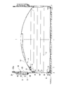


Classifications
-
- E—FIXED CONSTRUCTIONS
- E04—BUILDING
- E04H—BUILDINGS OR LIKE STRUCTURES FOR PARTICULAR PURPOSES; SWIMMING OR SPLASH BATHS OR POOLS; MASTS; FENCING; TENTS OR CANOPIES, IN GENERAL
- E04H7/00—Construction or assembling of bulk storage containers employing civil engineering techniques in situ or off the site
- E04H7/02—Containers for fluids or gases; Supports therefor
- E04H7/04—Containers for fluids or gases; Supports therefor mainly of metal
- E04H7/06—Containers for fluids or gases; Supports therefor mainly of metal with vertical axis
-
- E—FIXED CONSTRUCTIONS
- E04—BUILDING
- E04H—BUILDINGS OR LIKE STRUCTURES FOR PARTICULAR PURPOSES; SWIMMING OR SPLASH BATHS OR POOLS; MASTS; FENCING; TENTS OR CANOPIES, IN GENERAL
- E04H5/00—Buildings or groups of buildings for industrial or agricultural purposes
- E04H5/10—Buildings forming part of cooling plants
-
- E—FIXED CONSTRUCTIONS
- E04—BUILDING
- E04H—BUILDINGS OR LIKE STRUCTURES FOR PARTICULAR PURPOSES; SWIMMING OR SPLASH BATHS OR POOLS; MASTS; FENCING; TENTS OR CANOPIES, IN GENERAL
- E04H7/00—Construction or assembling of bulk storage containers employing civil engineering techniques in situ or off the site
- E04H7/02—Containers for fluids or gases; Supports therefor
- E04H7/04—Containers for fluids or gases; Supports therefor mainly of metal
- E04H7/06—Containers for fluids or gases; Supports therefor mainly of metal with vertical axis
- E04H7/065—Containers for fluids or gases; Supports therefor mainly of metal with vertical axis roof constructions
Definitions
- the present invention relates to a method for constructing a cylindrical tank. This application claims priority based on Japanese Patent Application No. 2013-135164 for which it applied to Japan on June 27, 2013, and uses the content here.
- a cylindrical shell with a double shell structure having an inner tank and an outer tank is used for storing low-temperature liquids such as LNG (liquefied natural gas) and LPG (liquefied petroleum gas).
- Patent Document 1 discloses a construction method for a cylindrical tank having a metal inner tank and a concrete outer tank.
- Patent Document 1 discloses a technique of simultaneously constructing a metal inner tank and a concrete outer tank in order to shorten the construction period of the cylindrical tank. Specifically, a jack stand is erected at the bottom of the outer tub, and the jack-up device is supported at a predetermined height (see FIG. 4B of Patent Document 1). And when carrying out the side wall construction of the outer tub, the inner tub roof and the outer tub roof are assembled on the bottom of the outer tub, and then the inner tub roof and the outer tub roof are raised by the jack-up device. A plurality of stages of inner tank side plates are attached in order from the top to the bottom. Thereby, the simultaneous construction with the metal inner tank and the concrete outer tank is realized.
- a metal inner tank and a concrete outer tank are constructed simultaneously.
- a part of the outer tank side wall is first constructed, and then the remaining part of the outer tank side wall and the inner tank are constructed in parallel.
- a suspended scaffold is formed on a part of the outer tank side wall previously constructed, and the scaffold is removed from the lower side. For this reason, it is difficult to assemble a jack-up device necessary for the construction of the inner tub and to construct a stand for holding the jack-up device.
- the present invention has been made in view of the above circumstances, and when a part of the outer tank side wall is first constructed and then the remaining part of the outer tank side wall and the inner tank are constructed in parallel, jack-up is performed. It is an object of the present invention to provide a method for constructing a cylindrical tank capable of easily performing assembly of the apparatus and construction of a mount for holding the jack-up apparatus.
- a first aspect of the present invention is a method for constructing a cylindrical tank having a metal inner tub and a concrete outer tub, wherein the side wall of the outer tub is constructed from the lower side to the middle of the finished height.
- the second aspect of the present invention is a method for constructing the cylindrical tank according to the first aspect, wherein in the step of assembling the inner tank, a process of attaching one inner tank side plate to the lower side of the knuckle part; A plurality of second suspension parts are provided above the plurality of suspension parts of the side wall of the outer tank between the process of attaching another inner tank side plate under the one inner tank side plate, The plurality of jack-up devices are replaced between the second suspension portion and the plurality of suspended members, and the knuckle portion is further lifted upward by the plurality of jack-up devices.
- a third aspect of the present invention is the method for constructing a cylindrical tank according to the first or second aspect, wherein the jackup device includes a jack body and a jackup rod connected to the jack body so as to be movable up and down.
- the jackup rod is formed by detachably connecting a plurality of rods in the length direction, and in the step of assembling the inner tub, the knuckle portion is attached to the roof by the plurality of jackup devices. When it is lifted together with the upper scaffolding, it has a process of removing the upper end rod from the lower end rod among the plurality of rods of the jackup rod.
- a pivotable davit is provided on the roof scaffold.
- At least a part of the roof top scaffold is connected to the plurality of suspended members, It is supported by the suspended member.
- the annular inner tank side plate assembled in advance is used in the cylindrical tank construction method according to the first to fifth aspects.
- the roof top scaffold that does not interfere with the side wall of the outer tub and the suspended scaffold is assembled at the knuckle portion. Therefore, after that, in the process of providing a plurality of suspension parts to be a rack for hanging the jackup device on the side wall of the outer tub, the process of attaching the jackup device between the suspension part and the suspended member, etc.
- the assembly of the jack-up device and the construction of the hanging portion can be easily and efficiently performed.
- a substantially disk-shaped foundation plate (bottom of the outer tub) 1 is constructed to form a bottom liner (not shown) on the top surface of the foundation plate 1.
- the inner tank anchor strap 2 is installed along the circumferential direction of the base plate 1 inside the outer peripheral edge of the base plate 1.
- the outer tank side wall (PC wall) 3 is placed from the lower stage side to the middle of the completed height (complete height).
- the intermediate height is not limited to the fifth stage, and can be set to an arbitrary height (stage).
- the construction port 4 is formed on the lower side of a part of the side wall (PC wall) 3 of the outer tank formed here, for example, from the second stage to the third stage. Further, since the remaining side walls 3 are stacked on a part of the side wall 3 to finally form the side wall 3 having nine levels, it is necessary to assemble a formwork for the remaining levels. For this reason, the suspension scaffold 5 is installed in the upper part of a part of the side wall 3, for example, at the fourth or higher stage.
- a plurality of leg mounts 6 for assembling the inner tub side plate are installed on the inner peripheral surface side of the side wall 3 along the circumferential direction.
- the gantry 6 with a leg is a portal gantry for supporting an inner tank side plate 7 to be described later.
- the leg-mounted base 6 is installed on the base plate 1 so as to straddle the annular region X, which is a region where a cylindrical inner tank formed by combining a plurality of inner tank side plates 7 is finally lowered. .
- each inner tank side plate 7 is assembled in an annular shape.
- the inner tank side plate 7 assembled here becomes the inner tank side plate 7 of the uppermost stage (9th step [# 9] in the present embodiment) of the inner tank.
- the inner tank side plate 7 is formed of a Ni steel material having excellent toughness and strength.
- the roof mount 8 is assembled at the center portion of the foundation plate 1.
- a plurality of knuckle plates 9 are attached to the upper end portion of the uppermost inner tank side plate 7, thereby assembling the knuckle plates 9.
- the knuckle plate 9 is connected to the outer peripheral edge portion of the inner tub roof 14 described later, and is curved downward. As described above, the upper end of the uppermost inner tank side plate 7 is connected to the lower end of the knuckle plate 9.
- a knuckle support 10 and a space keeper 11 are attached to the outer peripheral surface of the knuckle plate 9, respectively.
- a plurality (for example, 30) of knuckle supports 10 are provided at equal intervals along the circumferential direction of the knuckle plate 9, and one space keeper 11 is provided between each of them. It is done.
- reference numeral 12 denotes a roof bone of an outer tub roof described later
- reference numeral 13 denotes a gondola rail.
- the knuckle support 10 is made of a steel plate and forms a suspended member that is connected to a jack-up device described later. As shown in FIGS. 4 and 5, the knuckle support 10 has a pair of support plates 10a and 10a formed in a substantially triangular shape in a side view and a substantially square shape in a plan view sandwiched between the support plates 10a and 10a.
- the suspension plate 10b and the reinforcement plate 10c sandwiched between the support plates 10a and 10a and connected to the upper surface of the suspension plate 10b to reinforce the space between the support plates 10a and 10a and the suspension plate 10b. Has been.
- one side of the support plates 10a and 10a is curved corresponding to the curved shape of the knuckle plate 9, and is attached and fixed to the curved surface of the knuckle plate 9 by welding or the like.
- the suspended plate 10b and the reinforcing plate 10c are connected and fixed between the support plates 10a and 10a by welding, bolting, or the like as shown in FIG.
- the suspended plate 10b is fixed between the support plates 10a and 10a in a state where the outer end (end on the side wall 3 side) of the suspended plate 10b coincides with the outer ends of the support plates 10a and 10a.
- the suspended plate 10b is formed with a notch 10d that opens toward the side opposite to the knuckle plate 9, that is, toward the side wall 3 of the outer tub.
- the notch 10d serves as a suspended point connected to a jack-up device described later.
- the space keeper 11 is provided so as to protrude outward from the outer peripheral surface of the knuckle plate 9 as shown in FIGS. As shown in FIG. 6, the space keeper 11 is disposed between the knuckle supports 10 provided at equal intervals along the circumferential direction of the knuckle plate 9. The space keeper 11 is disposed at a substantially central portion between the adjacent knuckle supports 10 and 10, whereby the space keeper 11 is also provided at equal intervals along the circumferential direction of the knuckle plate 9. Accordingly, the space keeper 11 and the knuckle support 10 are alternately arranged at equal intervals along the circumferential direction of the knuckle plate 9.
- the space keeper 11 includes a pair of steel plates (not shown) attached to the knuckle plate 9 in the same manner as the support plate 10a, and H steel 11a sandwiched between these steel plates, It is formed with the steel plate 11b stuck on the outer end surface of the H steel 11a.
- the space keeper 11 is formed and arranged so that the outer end of the space keeper 11 is positioned outside the outer end of the suspended plate 10b (on the side wall 3 side of the outer tub).
- the space keeper 11 is formed and arranged so that the distance from the center of the knuckle plate 9 to the outer end of the space keeper 11 is longer than the distance from the center of the knuckle plate 9 to the outer end of the suspended plate 10b.
- the space keeper 11 can reduce the substantial clearance between the side wall 3 of the outer tub and the knuckle plate 9. Therefore, when the knuckle plate 9 is lifted by a jack-up device described later, even if the knuckle plate 9 is displaced in the horizontal direction due to the influence of an earthquake or the like, the amount of displacement is reduced and the space keeper 11 collides with the side wall 3 of the outer tub. Can reduce the impact.
- the inner tank roof block is mounted on the roof mount 8, and the inner tank roof (tank roof portion) 14 is assembled.
- an aerial work vehicle (not shown) is placed on the basic version 1.
- a part of the legged base 6 is constructed.
- the side walls 3 of the outer tub are sequentially stacked on the upper side using the suspension scaffold 5, and the side walls 3 of the outer tub are constructed up to the ninth stage (# 9) as the final stage as shown in FIG.
- the suspension scaffold 5 for forming the side wall 3 remains in a state of being assembled, for example, from the sixth stage to the seventh stage or more.
- the jack is placed on the knuckle plate 9 so as not to interfere with the side wall 3 while being separated from the inner peripheral surface of the side wall 3 of the outer tub and at a height that does not interfere with the suspension scaffold 5.
- the jack-up device scaffold 17 is formed in an annular shape along the circumferential direction of the annular knuckle plate 9, thereby preventing the knuckle plate 9 from falling down in the radial direction. Further, when assembling the scaffold 17 for the jack-up device, as shown in FIG. 8 and FIG. 9 showing the inner surface side of the main part of the side wall 3 of the outer tub in the process shown in FIG.
- the jackup device scaffold 17 is assembled at a position corresponding to the fourth step (# 4) to the fifth step (# 5) of the side wall 3 of the outer tub.
- suspension bases 18 (suspension parts) are provided at predetermined positions on the side wall 3, in the fifth embodiment (# 5) in this embodiment, using a scaffold 17 for a jack-up device. ) At equal intervals in the circumferential direction of the side wall 3.
- the suspension base 18 is provided so as to protrude substantially horizontally from the side wall 3 inwardly by being fastened and fixed firmly and detachably to an anchor plate embedded in the side wall 3 in advance.
- the jackup device 19 is attached between the suspension base 18 and the suspended plate 10b of the knuckle support 10 using the scaffold 17 for the jackup device.
- the jack-up device 19 is a center hole jack as shown in FIG. 10.
- the jack body 20 a is engaged with and supported by the suspension base 18, the upper end portion is attached to the jack body 20 a, and the lower end portion is the knuckle support 10.
- the description of the jack-up device scaffold 17 is omitted for easy viewing.
- the jackup rod 20 When attaching the jackup device 19, first, the jackup rod 20 is suspended with the jack body 20 a engaged and fixed on the suspension base 18, and the lower end of the jackup rod 20 is covered with the knuckle support 10. It inserts in the notch 10d of the suspension board 10b. And the lower end part of the jackup rod 20 is fixed to the suspended board 10b with the nut 19a prepared previously. Such an operation can be easily performed without any trouble by using the jack-up device scaffold 17 shown in FIG.
- each jack-up device 19 When a plurality of jack-up devices 19 are installed at predetermined intervals in the circumferential direction of the side wall 3 of the outer tub, and each jack-up device 19 is attached to the suspended plate 10b of the corresponding knuckle support 10, as shown in FIG.
- the roof mount 8 is removed. Accordingly, the weight of the tank constituent member is held by the plurality of jackup devices 19.
- a suspension base 18 is provided at a position corresponding to the fifth step (# 5) of the side wall 3, and the knuckle support 10 is provided at a position corresponding to the third step (# 3) of the side wall 3.
- the jack-up rod 20 is formed with a sufficient length corresponding to the length between the suspension base 18 and the knuckle support 10. However, as described later, when the jackup device 19 is operated and the jackup rod 20 is raised, the jackup rod 20 interferes with the suspended scaffold 5 positioned immediately above the jackup rod 20.
- the jack-up rod 20 is formed by detachably connecting a plurality of rods 20b by screwing or the like in the length direction as shown in FIG.
- the jackup rod 20 interferes with the suspension scaffold 5 by removing (separating) the rod 20b protruding upward from the suspension base 18 from the lower rod 20b. Can be prevented.
- symbol 15 in FIG. 8 is the davit installed in the top part of the scaffold 17 for jackup apparatuses at the time of formation of the scaffold 17 for jackup apparatuses.
- the davit 15 is provided so as to be pivotable, and is used for transferring the rod 20b detached (separated) from the lower rod 20b.
- reference numeral 21 in FIG. 8 is used to lift or suspend each component of the jackup device 19 or to suspend the rod 20b that is removed from the jackup rod 20 and transferred by the davit 15.
- It is a well-known suspension balance, and has a balance rod 21a and a weight 21b provided at one end of the balance rod 21a.
- the suspension balance 21 is suspended by a crane (not shown), thereby controlling each operation of raising and lowering and horizontal movement.
- the cold insulation work of the annular portion 16 and the cold insulation work of the central portion are performed in parallel on the basic version 1.
- pearlite concrete blocks 23a and 23b and a structural lightweight concrete block 24 are assembled on the bottom cooling resistance reducing material 22 under the legged base 6, as shown in FIG.
- An annular plate 16a is attached on the top.
- the annular portion 16 finally supports the assembled inner tank side plate 7. Therefore, the annular plate 16a of the annular portion 16 is formed thick, and its cold insulation structure is also formed of a hard material such as a concrete block.
- the knuckle plate 9 is lifted by the jack-up device 19, so that the knuckle plate 9 and the inner tank roof 14, the inner tank side plate 7, the knuckle support 10, the space keeper 11, the jack are supported.
- the tank constituent member Y including the up device scaffold 17 is raised.
- the jack main body 20 a is driven to rotate forward to raise the jack up rod 20 and jack up the tank constituent member Y being assembled together with the knuckle support 10.
- the knuckle plate 9 lifted by the jack-up device 19 is sufficiently thicker and stronger than the inner tank side plate 7 in order to connect the inner tank roof 14 and the inner tank side plate 7. Therefore, even if the weight including the inner tank side plate 7, the inner tank roof 14, and the jackup device scaffold 17 is added, it does not buckle.
- the next stage of the inner tank side plate 7 is carried into the space formed below the inner tank side plate 7.
- the inner tank side plate 7 is carried in via a construction port 4 provided in the side wall 3.
- a first transport device (not shown) is provided around the construction port 4, and the inner tank side plate 7 is sequentially passed from the outside of the side wall 3 through the construction port 4 onto the legged stand 6 by the first transport device. Be transported.
- a second transport device (not shown) is provided on the leg-mounted base 6 along the circumferential direction of the side wall 3.
- the second transport device has a rail (not shown) along the circumferential direction of the side wall 3, and the inner tank side plate 7 that has been transported onto the leg-mounted base 6 is further sequentially moved in the circumferential direction of the side wall 3. Transport.
- the inner tank side plate 7 that has been conveyed by the second conveying device is erected on the stand 6 with a leg, and is arranged in an annular shape below the jacked up inner tank side plate 7.
- the inner tank side plates 7 that are adjacent in the horizontal direction are integrally welded, and the inner tank side plates 7 that are lined up and down are also integrally welded, so that the inner tank side plate 7 is integrally cylindrical.
- the 8th (# 8) inner tank side plate 7 is attached below the 9th (# 9) inner tank side plate 7 which is the uppermost stage.
- a plurality of inner tank side plates 7 are connected in advance in the lateral direction outside the side wall 3 of the outer tank, taken into the side wall 3 and formed into an annular shape, and then the inner tank side plates 7 arranged vertically are welded together. You may do it. As described above, by connecting the plurality of inner tank side plates 7 in the lateral direction outside the side wall 3 with a limited working space, the welding operation is facilitated and the inner tank can be assembled efficiently.
- the upper end of the jackup rod 20 of the jackup device 19 protrudes upward from the suspension base 18 as shown in FIG. If the jack-up rod 20 rises further, it will interfere with the suspended scaffold 5 located immediately above it. Therefore, while the inner tank side plates 7 are being welded to each other, the rod 20b protruding upward from the suspension base 18 is removed from the lower side among the plurality of rods 20b constituting the jack-up rod 20.
- the rod 20b removed using the davit 15 installed in advance on the top of the jack-up device scaffold 17 is lowered onto the inner tank roof 14. That is, the removed rod 20b is lowered onto the inner tub roof 14 by the davit 15 capable of turning.
- a storage part (not shown) for temporarily storing materials such as the rods 20b is formed on the inner tank roof 14 in advance.
- the removal of the rod 20b, the hanging of the removed rod 20b onto the inner tank roof 14, the storage of the rod 20b in the storage unit, and the like are performed using the jack-up device scaffold 17. Further, the upper side of the jack-up device scaffold 17 is sequentially removed by the suspension balance 21 so that the jack-up device scaffold 17 does not interfere with the suspension scaffold 5.
- the tank constituent member Y is raised by almost one step of the inner tank side plate 7 by the jack-up device 19, and the next stage of the inner tank side plate 7 is further carried into the space formed below the inner tank side plate 7.
- the seventh stage (# 7) inner tank side plate 7 is attached as shown in FIG. Also at that time, the rod 20 b protruding upward from the suspension base 18 is removed, and the rod 20 b removed using the davit 15 is lowered onto the inner tank roof 14.
- the suspended scaffold 5 on the inner peripheral surface side of the side wall 3 is removed as shown in FIG.
- the side wall 3 of the outer tank is completed to the 9th stage (# 9) which is the uppermost stage. . Therefore, since the formwork etc. for forming the side wall 3 can be removed, the suspension scaffold 5 in the inner peripheral surface side of the side wall 3 can be removed.
- the scaffold on the outer peripheral surface side of the side wall 3 is left without being removed because it is necessary in a later process.
- the 2nd suspension mount frame 25 is installed in the top part of the side wall 3 of an outer tank.
- the tank constituent member Y including the eighth and seventh inner tank side plates 7) is once lowered onto the leg-mounted base 6 by jacking down.
- the jack-up rod 20 of the jack-up device 19 shown in FIG. 10 is once removed from the suspended plate 10b of the knuckle support 10 by using a suspension balance 21, a crane or the like.
- the jack body 20 a of the jack-up device 19 is removed from the suspension base 18.
- the jack-up device 19 is removed from between the side wall 3 of the outer tub and the knuckle plate 9.
- the suspension base 18 is removed from the side wall 3.
- the jack body 20a of the jack-up device 19 is attached to the second suspension base 25 shown in FIG.
- the upper side of the jack-up rod 20 was once removed so as not to be interfered with the suspension scaffold 5 and stored in the storage section on the inner tank roof 14.
- the rod 20b stored on the inner tank roof 14 is again jacked. It is attached to the up rod 20 and the jack up rod 20 is lengthened. In this embodiment, as shown in FIG.
- the jack-up rod 20 is separately prepared in advance in order to hang down from the 9th stage (# 9) to the 5th stage (# 5), which is the uppermost stage of the side wall 3 of the outer tub.
- the spare rod 20b thus added is further added, and the jack-up rod 20 is adjusted to a desired length. This operation can also be performed by using the jackup device scaffold 17 shown in FIG.
- the jack-up rod 20 When the jack-up rod 20 is adjusted to a desired length in this way, the lower end side of the jack-up rod 20 is inserted into the notch 10d of the suspended plate 10b of the knuckle support 10 again. And the lower end part of the jackup rod 20 is fixed to the suspended board 10b with the nut 19a. Thereby, the jack-up device 19 is replaced. When the replacement of the jack-up device 19 is completed in this way, the jack-up device scaffold 17 is removed as shown in FIG.
- the knuckle plate 9 is lifted by the jack-up device 19, and the tank constituent member Y is raised by almost one step of the inner tank side plate 7.
- the next-stage inner tank side plate 7 is further carried into the space formed below the inner tank side plate 7, and hereinafter, the above-described eighth stage (# 8) and seventh stage (# 7) inner tanks.
- the sixth stage (# 6) inner tank side plate 7 is attached as shown in FIG.
- the outer tank roof 26 is attached on the inner tank roof 14.
- the outer tub roof 26 is attached by attaching a connecting material (not shown) made of a number of channel steels on the inner tub roof 14 and attaching the outer tub roof 26 to these connecting materials.
- a connecting material (not shown) made of a number of channel steels on the inner tub roof 14 and attaching the outer tub roof 26 to these connecting materials.
- work which sticks a side part liner (not shown) with respect to the internal peripheral surface of the side wall 3 of an outer tank is started.
- the tank constituent member Y is lifted by the jack-up device 19, the inner tank side plate 7 of the next stage is carried below the inner tank side plate 7 (tank constituent member Y), and the tank constituent member Y of the inner tank side plate 7 carried in The attachment to the (inner tank side plate 7) is sequentially repeated, and as shown in FIG. 17, the inner tank side plate 7 is attached to the first stage (# 1) at the lowest level. Thereby, the side wall of an inner tank is completed.
- various materials 27 are placed on the side walls separately from the loading of the inner tank side plate 7. Carry on the basic version 1 in 3.
- a work scaffold 28 is assembled on the outer tank roof 26.
- the leg mount 6 is removed, and the lower part of the tank constituent member Y is made a space.
- the jack constituent device Y is jacked down by the jack-up device 19, and the outer peripheral end of the roof bone 12 of the outer tub roof 26 is connected and fixed to the mounting end 29 embedded in the top inner peripheral surface of the side wall 3 of the outer tub.
- the connection material (not shown) which connects between the outer tank roof 26 and the inner tank roof 14 is removed, and the connection between these is cancelled
- the tank constituent member Y is jacked down again by the jack-up device 19, and the lowermost lower end portion of the inner tank side plate 7 is lowered onto the annular portion 16. Then, the lowermost lower end portion of the inner tank side plate 7 is attached to the inner tank anchor strap 2 installed on the base plate 1.
- the knuckle support 10 is removed from the knuckle plate 9, and the space keeper 11 is further removed as necessary.
- the polyurethane foam (PUF) which is a thermal resistance relaxation material is sprayed with respect to the side part liner (not shown) stuck on the internal peripheral surface of the side wall 3 of an outer tank.
- the jack-up device 19 and the second suspension mount 25 are also removed.
- the construction port 4 is closed, a pump barrel (not shown) is installed, water filling is performed, and a pressure resistance / air tightness test is performed.
- a cold insulating material such as pearlite (not shown) is filled between the inner tank and the outer tank to perform the cold insulation work between the inner and outer tanks.
- the cylindrical tank 100 is completed when the painting work and the pipe cooling work are performed.
- the scaffold 17 for the jack-up device (rooftop scaffold) is assembled on the knuckle plate 9 so as not to interfere with the side wall 3 and the suspended scaffold 5 of the outer tub. Therefore, after that, a step of providing a plurality of suspension bases 18 for suspending the jackup device 19 on the side wall 3 of the outer tub using the jackup device scaffold 17, or between the suspension base 18 and the knuckle support 10. Each of the steps for attaching the jack-up device 19 can be easily performed.
- a part of the outer tank side wall 3 is first constructed, and then the remaining part of the outer tank side wall 3 and the inner tank are constructed in parallel. Even when it is performed, in order to assemble the scaffold 17 for the jackup device (rooftop scaffold) on the knuckle plate 9, the jackup is performed without being interfered with the side wall 3 of the outer tub or the suspension scaffold 5 formed on the upper part thereof.
- the assembly of the device 19 and the construction of the suspension base 18 can be easily and efficiently performed. Thereby, a construction period can be shortened and cost can be reduced.
- the process of replacing the jackup device 19 by providing the second suspension rack 25 above the suspension rack 18 is performed. Done. Also in such a process, the work of disassembling the jack-up device 19 and removing the suspension base 18 from the side wall 3 can be easily performed using the jack-up device scaffold 17.
- the pivotable davit 15 is provided on the scaffold 17 for the jack-up device, when the rod 20b at the upper end of the jack-up rod 20 is removed from the rod 20b at the lower end, the rod 20b removed by the davit 15 is removed from the inner tank. It can be easily suspended on the roof 14.
- the jack-up device scaffold 17 can be easily attached to the knuckle plate 9. Further, when disassembling the jackup device scaffold 17, the work is mainly performed between the jackup device scaffold 17 and the knuckle support 10 without directly working on the knuckle plate 9. Can be removed from the knuckle plate 9. Therefore, it is possible to prevent the knuckle plate 9 remaining as a constituent member of the completed cylindrical tank 100 from being damaged due to the disassembly of the jackup device scaffold 17.
- the knuckle plate 9 is attached to the upper side of the inner tank side plate 7 that has been assembled in advance. Rather than first assembling the knuckle plate 9 curved in the height direction into an annular shape, the inner tank side plate 7 not curved in the height direction is assembled into an annular shape, and then the knuckle plate 9 is attached to the inner tank side plate 7 Is easy. Therefore, the assembly of the knuckle plate 9 can be facilitated.
- the inner tank roof 14 and the outer tank roof 26 are horizontal in the outer tank.
- the space keeper 11 is provided between the knuckle supports 10 and 10 so as to be positioned outside the knuckle support 10 (on the side of the side wall 3 of the outer tub), the space keeper 11 and the knuckle of the outer tub side wall 3 are provided.
- the substantial clearance between the plate 9 can be reduced. Therefore, even if the knuckle plate 9 is displaced in the horizontal direction due to the influence of an earthquake or the like, the amount of displacement can be reduced.
Landscapes
- Engineering & Computer Science (AREA)
- Architecture (AREA)
- Civil Engineering (AREA)
- Structural Engineering (AREA)
- General Engineering & Computer Science (AREA)
- Filling Or Discharging Of Gas Storage Vessels (AREA)
Abstract
金属製の内槽とコンクリート製の外槽とを有する円筒型タンクの構築方法である。外槽の側壁(3)を完成高さの途中まで施工する工程、側壁(3)の内側にて円環状のナックルプレート(9)を組み立てる工程、懸垂足場(5)を利用して側壁(3)の残りを施工する工程、ナックルプレート(9)にナックルサポート(10)を設ける工程、ナックルプレート(9)にジャッキアップ装置用足場(17)を組み立てる工程、側壁(3)に吊り架台(18)を設ける工程、吊り架台(18)とナックルサポート(10)との間にジャッキアップ装置(19)を取り付ける工程、ジャッキアップ装置(19)によってナックルプレート(9)を吊り上げ、ナックルプレート(9)の下側に内槽側板(7)を取り付けて内槽を組み立てる工程、を備える。上記構成により、ジャッキアップ装置の組み立てやジャッキアップ装置を保持するための架台等の施工を容易に行える円筒型タンクの構築方法を提供することができる。
Description
本発明は、円筒型タンクの構築方法に関する。
本願は、2013年6月27日に日本に出願された特願2013-135164号に基づき優先権を主張し、その内容をここに援用する。
本願は、2013年6月27日に日本に出願された特願2013-135164号に基づき優先権を主張し、その内容をここに援用する。
内槽と外槽とを有する二重殻構造の円筒型タンクは、LNG(液化天然ガス)やLPG(液化石油ガス)等の低温液体の貯蔵に用いられている。特許文献1には、金属製の内槽とコンクリート製の外槽とを有する円筒型タンクの建設工法が開示されている。
特許文献1には、円筒型タンクの工期の短縮化を図るため、金属製の内槽とコンクリート製の外槽とを同時に施工する手法が開示されている。具体的には、外槽の底部にジャッキ架台を立設させ、ジャッキアップ装置を所定高さに支持させる(特許文献1の図4(b)参照)。そして、外槽の側壁工事を行うときに、外槽の底部上で内槽屋根と外槽屋根とを組み立て、次いで、ジャッキアップ装置により内槽屋根と外槽屋根とを上昇させながら内槽屋根に複数段の内槽側板を最上段から最下段へと順番に取り付ける。これにより、金属製の内槽とコンクリート製の外槽との同時施工を実現している。
ところで、上述の従来技術では、金属製の内槽とコンクリート製の外槽とを同時に施工している。しかしながら、施工上の理由によって、例えば外槽側壁の一部を先に施工し、その後、外槽側壁の残部の施工と内槽の施工とを並行して行う場合もある。
この場合には、外槽側壁の残部の施工のために、先に施工した外槽側壁の一部の上に懸垂足場を形成し、その下側からは足場を撤去する。このため、内槽の施工のために必要なジャッキアップ装置の組み立てやジャッキアップ装置を保持するための架台等の施工を行うのが困難である。
この場合には、外槽側壁の残部の施工のために、先に施工した外槽側壁の一部の上に懸垂足場を形成し、その下側からは足場を撤去する。このため、内槽の施工のために必要なジャッキアップ装置の組み立てやジャッキアップ装置を保持するための架台等の施工を行うのが困難である。
本発明は前記事情に鑑みてなされたもので、外槽側壁の一部を先に施工し、その後、外槽側壁の残部の施工と内槽の施工とを並行して行う場合に、ジャッキアップ装置の組み立てやジャッキアップ装置を保持するための架台等の施工を容易に行うことが可能な円筒型タンクの構築方法を提供することを目的とする。
本発明の第一の態様は、金属製の内槽とコンクリート製の外槽とを有する円筒型タンクの構築方法であって、前記外槽の側壁を下段側から完成高さの途中まで施工する工程と、前記外槽の前記側壁の内側にて円環状のナックル部を組み立てる工程と、前記外槽の前記側壁の残りを、前記側壁に形成した懸垂足場を利用して施工する工程と、前記ナックル部に、複数のジャッキアップ装置に連結する複数の被吊り部材を設ける工程と、前記ナックル部に、前記外槽の前記側壁及び前記懸垂足場に干渉しない屋根上足場を組み立てる工程と、前記外槽の前記側壁に、前記複数のジャッキアップ装置を吊るための複数の吊り部を設ける工程と、前記外槽の前記側壁の前記複数の吊り部と前記ナックル部の前記複数の被吊り部材との間にそれぞれ前記複数のジャッキアップ装置を取り付ける工程と、前記複数のジャッキアップ装置によって前記ナックル部を前記屋根上足場とともに吊り上げて上昇させ、上昇した前記ナックル部の下側に内槽側板を取り付けて前記内槽を組み立てる工程と、を備える。
また、本発明の第二の態様は、上記第一の態様に係る円筒型タンクの構築方法において、前記内槽を組み立てる工程では、前記ナックル部の下側に一の内槽側板を取り付ける処理と、前記一の内槽側板の下に他の内槽側板を取り付ける処理との間に、前記外槽の前記側壁の前記複数の吊り部より上方に複数の第2の吊り部を設け、前記複数の第2の吊り部と前記複数の被吊り部材との間にそれぞれ前記複数のジャッキアップ装置を盛り替え、前記複数のジャッキアップ装置によって前記ナックル部をさらに上方に吊り上げて上昇させる処理を有する。
また、本発明の第三の態様は、上記第一または第二の態様に係る円筒型タンクの構築方法において、前記ジャッキアップ装置はジャッキ本体と前記ジャッキ本体に昇降可能に連結するジャッキアップロッドとを有し、前記ジャッキアップロッドは複数のロッドを長さ方向に着脱可能に連結することにより形成されており、前記内槽を組み立てる工程では、前記複数のジャッキアップ装置によって前記ナックル部を前記屋根上足場とともに吊り上げて上昇させた際、前記ジャッキアップロッドの前記複数のロッドのうち、上端のロッドを下端側のロッドから取り外す処理を有する。
また、本発明の第四の態様は、上記第三の態様に係る円筒型タンクの構築方法において、前記屋根上足場に旋回可能なダビットが設けられる。
また、本発明の第五の態様は、上記第一ないし第四の態様に係る円筒型タンクの構築方法において、前記屋根上足場の少なくとも一部は前記複数の被吊り部材に連結され、前記複数の被吊り部材によって支持される。
また、本発明の第六の態様は、上記第一ないし第五の態様に係る円筒型タンクの構築方法において、前記円環状のナックル部を組み立てる工程では、予め組み立てた円環状の内槽側板の上側に前記ナックル部を取り付けることにより前記ナックル部を組み立て、前記内槽を組み立てる工程では、前記複数のジャッキアップ装置によって上昇させた前記ナックル部の下側の内槽側板に、次の内槽側板を取り付ける。
本発明の円筒型タンクの構築方法によれば、ナックル部に、外槽の側壁及び懸垂足場に干渉しない屋根上足場を組み立てる。したがって、その後、外槽の側壁にジャッキアップ装置を吊るための架台となる複数の吊り部を設ける工程や、吊り部と被吊り部材との間にそれぞれジャッキアップ装置を取り付ける工程などの際に、屋根上足場を利用することでジャッキアップ装置の組み立てや吊り部の施工を容易にかつ効率的に行うことができる。
以下、図面を参照して本発明に係る円筒型タンクの構築方法の一実施形態を詳しく説明する。なお、以下の図面においては、各部材を認識可能な大きさとするため、各部材の縮尺を適宜変更している。以下の説明では、円筒型タンクとして、LNGを貯蔵する地上式のPC(プレストレスコンクリート)二重殻貯槽を例示する。
まず、図1に示すように、略円板状の基礎版(外槽の底部)1の工事を行い、基礎版1の上面に底部ライナー(図示せず)を形成する。その際、本実施形態では、基礎版1の外周縁部より内側に、基礎版1の周方向に沿って内槽アンカーストラップ2を設置する。
次に、基礎版1の外周縁部の、内槽アンカーストラップ2より外側に、外槽の側壁(PC壁)3を下段側から完成時の高さ(完成高さ)の途中まで、本実施形態では全部で9段積み上げて形成する側壁3の5段目(#5)まで、形成する。ただし、途中の高さは5段目に限定されることなく、任意の高さ(段)とすることができる。
次に、基礎版1の外周縁部の、内槽アンカーストラップ2より外側に、外槽の側壁(PC壁)3を下段側から完成時の高さ(完成高さ)の途中まで、本実施形態では全部で9段積み上げて形成する側壁3の5段目(#5)まで、形成する。ただし、途中の高さは5段目に限定されることなく、任意の高さ(段)とすることができる。
また、ここで形成する外槽の側壁(PC壁)3の一部の下段側、例えば2段目から3段目にかけて、工事口4を形成する。さらに、側壁3の一部の上に残りの段の側壁を積み上げて最終的に9段からなる側壁3を形成するため、残りの段のための型枠を組み立てる必要がある。このため、側壁3の一部の上部側、例えば4段目以上の部位に懸垂足場5を設置しておく。
このようにして外槽の側壁3の一部を形成したら、側壁3の内周面側にその周方向に沿って、内槽側板組立用の複数の脚付架台6を設置する。脚付架台6は、後述する内槽側板7を支持するための門型架台である。脚付架台6は、複数の内槽側板7が組み合わされて形成される円筒状の内槽が最終的に下ろされる領域となるアニュラー領域Xを跨ぐようにして、基礎版1上に設置される。
次に、図2に示すように懸垂足場5を利用して側壁3の一部の上にコンクリートを打設し、6段目(#6)の側壁を形成する。なお、側壁3の施工にあたっては、側壁3の上部側を順次形成するに伴い、懸垂足場5についても順次上側に組み上げていき、不要となった下側の懸垂足場5は順次撤去していく。
また、これに並行して脚付架台6上に、内槽の側壁の一部となる複数の内槽側板7を側壁3の周方向に沿って立設し、横方向に隣り合う内槽側板7を一体的に溶接する。これにより、各内槽側板7を円環状に組み立てる。なお、ここで組み立てる内槽側板7は、内槽の最上段(本実施形態では9段目[#9])の内槽側板7となる。内槽側板7は、優れた靱性と強度を備えるNi鋼材等によって形成されている。
また、側壁3の内部では、基礎版1の中央部にて屋根架台8を組み立てる。
また、側壁3の内部では、基礎版1の中央部にて屋根架台8を組み立てる。
次に、図3に示すように最上段の内槽側板7の上端部に複数のナックルプレート9(ナックル部)を取り付け、これによってナックルプレート9を組み立てる。ナックルプレート9は、後述する内槽屋根14の外周縁部と接続し、下方に向けて湾曲する。前述したように、ナックルプレート9の下端部に最上段の内槽側板7の上端部が接続される。
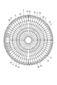
図4~図6に示すように、ナックルプレート9の外周面には、ナックルサポート10とスペースキーパー11とがそれぞれ取り付けられる。本実施形態では、図6に示すようにナックルプレート9の周方向に沿って複数(例えば30個)のナックルサポート10が等間隔で設けられ、これらの間にそれぞれ1個ずつスペースキーパー11が設けられる。なお、図6中において符号12は後述する外槽屋根の屋根骨、符号13はゴンドラレールである。
ナックルサポート10は、鋼板製であり、後述するジャッキアップ装置に連結される被吊り部材を形成する。図4、図5に示すように、ナックルサポート10は、側面視で略三角形状に形成された一対のサポート板10a、10aと、サポート板10a、10a間に挟持された平面視で略正方形状の被吊り板10bと、サポート板10a、10a間に挟持され、かつ被吊り板10bの上面に連結してサポート板10a、10aと被吊り板10bとの間を補強する補強板10cとによって形成されている。
図4に示すように、サポート板10a、10aの一辺部は、ナックルプレート9の湾曲形状に対応して湾曲しており、ナックルプレート9の湾曲面に溶接等によって取り付け固定されている。被吊り板10bと補強板10cとは、溶接等によって互いに連結された状態で、図5に示すようにサポート板10a、10a間に溶接やボルト止め等によって取り付け固定されている。被吊り板10bの外側端(側壁3側の端)がサポート板10a、10aの外側端と一致した状態で、被吊り板10bはサポート板10a、10a間に固定されている。被吊り板10bには、ナックルプレート9と反対の側、すなわち外槽の側壁3側に向かって開口する切欠10dが形成されている。切欠10dは、後述するジャッキアップ装置に連結する被吊り点となる。
スペースキーパー11は、図4、図5に示すようにナックルプレート9の外周面から外側に突出するよう設けられる。図6に示したように、スペースキーパー11は、ナックルプレート9の周方向に沿って等間隔で設けられたナックルサポート10のそれぞれの間に配設されている。スペースキーパー11は、隣り合うナックルサポート10、10間のほぼ中央部に配設されており、これによってスペースキーパー11も、ナックルプレート9の周方向に沿って等間隔で設けられている。したがって、スペースキーパー11とナックルサポート10とは、ナックルプレート9の周方向に沿って互いに等間隔で交互に配置される。
スペースキーパー11は、図4、図5に示すように例えばナックルプレート9にサポート板10aと同様に取り付けられた一対の鋼板(図示せず)と、これら鋼板間に挟持されたH鋼11aと、H鋼11aの外端面に貼設された鋼板11bとによって形成されている。スペースキーパー11は、本実施形態では、スペースキーパー11の外側端が被吊り板10bの外側端より外側(外槽の側壁3側)に位置するよう形成配置される。
すなわち、ナックルプレート9の中心からスペースキーパー11の外側端までの距離が、ナックルプレート9の中心から被吊り板10bの外側端までの距離より長くなるようにスペースキーパー11を形成配置する。このように配置することで、スペースキーパー11によって外槽の側壁3とナックルプレート9との間の実質的なクリアランスを小さくすることができる。したがって、後述するジャッキアップ装置によってナックルプレート9を吊り上げた際、地震等の影響によってナックルプレート9が水平方向に変位しても、変位量を小さくしてスペースキーパー11が外槽の側壁3に衝突した際の衝撃を緩和することができる。
次に、図7に示すように屋根架台8上に内槽屋根ブロックを搭載し、内槽屋根(タンク屋根部)14を組み立てる。
また、基礎版1上に高所作業車(図示せず)を乗り入れる。また、脚付架台6の下のアニュラー領域Xにアニュラー部16を形成するために、脚付架台6の一部を施工する。
また、外槽の側壁3についても懸垂足場5を利用して順次上側に積み上げていき、図7に示すように外槽の側壁3を最終段となる9段目(#9)まで施工する。なお、この時点では、側壁3の形成のための懸垂足場5が、例えば6段目から7段目以上に組まれた状態のまま残っている。
また、基礎版1上に高所作業車(図示せず)を乗り入れる。また、脚付架台6の下のアニュラー領域Xにアニュラー部16を形成するために、脚付架台6の一部を施工する。
また、外槽の側壁3についても懸垂足場5を利用して順次上側に積み上げていき、図7に示すように外槽の側壁3を最終段となる9段目(#9)まで施工する。なお、この時点では、側壁3の形成のための懸垂足場5が、例えば6段目から7段目以上に組まれた状態のまま残っている。
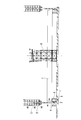
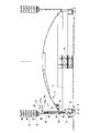
次に、図8に示すように、ナックルプレート9上に、外槽の側壁3の内周面から離間して側壁3に干渉しない状態で、かつ、懸垂足場5に干渉しない高さで、ジャッキアップ装置用足場(屋根上足場)17を組み立てる。ジャッキアップ装置用足場17は、環状に形成されているナックルプレート9の周方向に沿って環状に形成され、これによってナックルプレート9が半径方向へ倒れることを防止する。また、ジャッキアップ装置用足場17を組み立てる際には、図8、及び図8に示した工程での外槽の側壁3の要部内面側を示す図9に示すように、ジャッキアップ装置用足場17を複数のナックルサポート10に取り付けることで、ジャッキアップ装置用足場17のほぼ全体を複数のナックルサポート10に支持させる。そして、倒れ防止材(図示せず)をジャッキアップ装置用足場17とナックルプレート9や内槽屋根14との間に設ける。これにより、ナックルプレート9や内槽屋根14に固定されたジャッキアップ装置用足場17が形成される。本実施形態では、図8に示すように外槽の側壁3のほぼ4段目(#4)から5段目(#5)に対応する位置に、ジャッキアップ装置用足場17を組み立てる。
そして、図8、図9に示すように、ジャッキアップ装置用足場17を利用して、側壁3の所定位置、本実施形態では5段目(#5)に、複数の吊り架台18(吊り部)を側壁3の周方向に等間隔となるように設置する。具体的には、吊り架台18を、例えば側壁3に予め埋め込んだアンカープレートに強固かつ着脱可能に締結固定することにより、側壁3からその内方に向けて略水平に突出するように設ける。
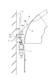
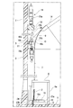
次に、ジャッキアップ装置用足場17を利用して、吊り架台18とナックルサポート10の被吊り板10bとの間に、それぞれジャッキアップ装置19を取り付ける。ジャッキアップ装置19は、図10に示すようにセンターホールジャッキであり、吊り架台18に係合され支持されるジャッキ本体20aと、ジャッキ本体20aに上端部が取り付けられ、下端部がナックルサポート10の被吊り板10bに取り付けられたジャッキアップロッド20と、ジャッキアップロッド20の下端部を被吊り板10bに取り付けるためのナット19aと、を有する。なお、図10では、見やすくするためにジャッキアップ装置用足場17の記載を省略している。
ジャッキアップ装置19を取り付ける際には、まず、吊り架台18の上にジャッキ本体20aを係合させ固定した状態でジャッキアップロッド20を垂下させ、ジャッキアップロッド20の下端部をナックルサポート10の被吊り板10bの切欠10d内に差し入れる。そして、予め用意したナット19aによってジャッキアップロッド20の下端部を被吊り板10bに固定する。このような作業は、図9に示したジャッキアップ装置用足場17を利用することで支障なく容易に行うことができる。
複数のジャッキアップ装置19を、外槽の側壁3の周方向に所定間隔で設置し、さらにそれぞれのジャッキアップ装置19を対応するナックルサポート10の被吊り板10bに取り付けたら、図8に示すように屋根架台8を撤去する。これにより、タンク構成部材の重量が複数のジャッキアップ装置19によって保持された状態となる。
ここで、図8に示すように、側壁3の5段目(#5)に対応する位置に吊り架台18が設けられ、側壁3の3段目(#3)に対応する位置にナックルサポート10が設けられる。ジャッキアップロッド20は、吊り架台18とナックルサポート10との間の長さに対応する充分な長さに形成されている。しかし、後述するようにジャッキアップ装置19を稼働させてジャッキアップロッド20を上昇させた際には、ジャッキアップロッド20がその直上に位置する懸垂足場5と干渉してしまう。
この問題を解消するために、ジャッキアップロッド20は、図10に示すように、複数のロッド20bを長さ方向に螺子止め等によって着脱可能に連結することにより形成される。これにより、ジャッキアップロッド20を上昇させた際、吊り架台18より上方に突出したロッド20bをその下側のロッド20bから取り外す(切り離す)ことにより、ジャッキアップロッド20が懸垂足場5に干渉するのを防止することができる。
なお、図8中の符号15はジャッキアップ装置用足場17の形成時に、ジャッキアップ装置用足場17の頂部に設置したダビットである。ダビット15は、旋回可能に設けられ、下側のロッド20bから取り外した(切り離した)ロッド20bを移送するために用いられる。
また、図8中の符号21は、ジャッキアップ装置19の各構成部材の吊り上げや吊り下げを行ったり、ジャッキアップロッド20から取り外されてダビット15によって移送されたロッド20bを吊り下げたりするための公知の吊り天秤であり、天秤棒21aと、天秤棒21aの一方の端部に設けられる錘21bとを有する。吊り天秤21は、図示しないクレーンによって吊られており、これによって昇降や水平移動の各動作が制御される。
また、図8中の符号21は、ジャッキアップ装置19の各構成部材の吊り上げや吊り下げを行ったり、ジャッキアップロッド20から取り外されてダビット15によって移送されたロッド20bを吊り下げたりするための公知の吊り天秤であり、天秤棒21aと、天秤棒21aの一方の端部に設けられる錘21bとを有する。吊り天秤21は、図示しないクレーンによって吊られており、これによって昇降や水平移動の各動作が制御される。
また、このような工程中、基礎版1上では、アニュラー部16の保冷工事及び中央部の保冷工事が並行して行われる。アニュラー部16の保冷工事においては、図10に示すように脚付架台6の下で、底部冷熱抵抗緩和材22の上にパーライトコンクリートブロック23a、23b、構造用軽量コンクリートブロック24が組み立てられ、その上にアニュラープレート16aが取り付けられる。アニュラー部16は、組み立てられた内槽側板7を最終的に支持する。したがって、アニュラー部16のアニュラープレート16aは厚く形成され、またその保冷構造もコンクリートブロック等の硬質な材料で形成される。
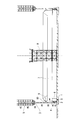
次に、図11に示すようにジャッキアップ装置19でナックルプレート9を吊り上げることにより、ナックルプレート9とこれに支持される内槽屋根14、内槽側板7、ナックルサポート10、スペースキーパー11、ジャッキアップ装置用足場17を含むタンク構成部材Yを上昇させる。具体的には、ジャッキ本体20aを正転駆動させることによって、ジャッキアップロッド20を上昇させ、ナックルサポート10とともに組み立て途中のタンク構成部材Yをジャッキアップする。
ここで、ジャッキアップ装置19によって吊り上げられるナックルプレート9は、内槽屋根14と内槽側板7とを接続するために、内槽側板7より板厚が充分に厚く、強度が高い。したがって、内槽側板7や内槽屋根14、さらにジャッキアップ装置用足場17を含む重量が付加されても座屈することがない。
ジャッキアップ装置19によってタンク構成部材Yを内槽側板7のほぼ一段分上昇させたら、内槽側板7の下方に形成された空間に次の段の内槽側板7を搬入する。内槽側板7の搬入は、側壁3に設けられた工事口4を介して行う。工事口4の周辺には第1搬送装置(図示せず)が設けられており、第1搬送装置によって側壁3の外から工事口4を通って脚付架台6上に内槽側板7が順次搬送される。また、脚付架台6上には、側壁3の周方向に沿って第2搬送装置(図示せず)が設けられている。第2搬送装置は、側壁3の周方向に沿うレール(図示せず)等を有しており、脚付架台6上に搬送されてきた内槽側板7を、さらに側壁3の周方向に順次搬送する。
次に、第2搬送装置で搬送されてきた内槽側板7を脚付架台6上に立設し、ジャッキアップされた内槽側板7の下方に円環状に配置する。そして、図12に示すように横方向に隣り合う内槽側板7を一体的に溶接し、上下に並ぶ内槽側板7同士も一体的に溶接することで、内槽側板7を一体の円筒形状に形成する。すなわち、最上段となる9段目(#9)の内槽側板7の下に8段目(#8)の内槽側板7を取り付ける。
なお、複数の内槽側板7同士を外槽の側壁3の外で予め横方向に連結し、これを側壁3内に取り込んで環状に形成した後、上下に並ぶ内槽側板7同士を溶接するようにしてもよい。このように複数の内槽側板7の横方向の連結を作業空間の制限の少ない側壁3の外で行うことにより、溶接作業が容易になり、効率よく内槽を組み立てることができる。
このようにしてジャッキアップを行うと、図12に示したように、ジャッキアップ装置19のジャッキアップロッド20の上端が吊り架台18より上方に突出する。ジャッキアップロッド20がそれ以上上昇するとその直上に位置する懸垂足場5に干渉してしまう。そこで、内槽側板7同士の溶接等を行っている間に、ジャッキアップロッド20を構成する複数のロッド20bのうち、吊り架台18より上方に突出したロッド20bをその下側から取り外す。
そして、予めジャッキアップ装置用足場17の頂部に設置したダビット15を用いて取り外したロッド20bを内槽屋根14上に降ろす。すなわち、取り外したロッド20bを旋回可能なダビット15によって内槽屋根14上に降ろす。内槽屋根14上には、予めロッド20b等の資材を一時的に保管しておく保管部(図示せず)を形成しておく。ロッド20bの取り外し、取り外したロッド20bの内槽屋根14上への吊り降ろし、及びロッド20bの保管部での保管等については、ジャッキアップ装置用足場17を利用して行う。また、ジャッキアップ装置用足場17が懸垂足場5と干渉しないよう、吊り天秤21によってジャッキアップ装置用足場17の上部側を順次撤去する。
次に、ジャッキアップ装置19によりタンク構成部材Yを内槽側板7のほぼ一段分上昇させ、内槽側板7の下方に形成された空間にさらに次の段の内槽側板7を搬入する。前述した8段目(#8)の内槽側板7の取り付けと同様にして、図13に示すように7段目(#7)の内槽側板7を取り付ける。その際にも、吊り架台18より上方に突出したロッド20bを取り外し、ダビット15を用いて取り外されたロッド20bを内槽屋根14上に降ろす。
このようにして9段目(#9)から7段目(#7)までの内槽側板7を取り付けたら、図14に示すように側壁3の内周面側の懸垂足場5を撤去する。通常、9段目(#9)から7段目(#7)までの内槽側板7を取り付ける間に、外槽の側壁3は最上段となる9段目(#9)まで完成してしまう。したがって、側壁3を形成するための型枠等を取り外すことが可能なため、側壁3の内周面側にある懸垂足場5を撤去することができる。なお、側壁3の外周面側の足場等については、後工程で必要となるため撤去せずに残しておく。
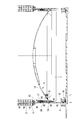
次に、ジャッキアップ装置19の盛り替えを行うため、図14に示すように外槽の側壁3の頂部に第2の吊り架台25を設置する。また、ジャッキダウンして一旦タンク構成部材Y(8段目や7段目の内槽側板7も含む)を脚付架台6上に降ろす。
続いて、図10に示したジャッキアップ装置19のジャッキアップロッド20を、吊り天秤21やクレーン等を利用して一旦ナックルサポート10の被吊り板10bから取り外す。また、ジャッキアップ装置19のジャッキ本体20aを吊り架台18から取り外す。
これにより、ジャッキアップ装置19は外槽の側壁3とナックルプレート9との間から取り外される。さらに、吊り架台18を側壁3から取り外す。これら一連の作業についても、ジャッキアップ装置用足場17を利用して行う。
続いて、図10に示したジャッキアップ装置19のジャッキアップロッド20を、吊り天秤21やクレーン等を利用して一旦ナックルサポート10の被吊り板10bから取り外す。また、ジャッキアップ装置19のジャッキ本体20aを吊り架台18から取り外す。
これにより、ジャッキアップ装置19は外槽の側壁3とナックルプレート9との間から取り外される。さらに、吊り架台18を側壁3から取り外す。これら一連の作業についても、ジャッキアップ装置用足場17を利用して行う。
そして、ジャッキアップ装置19のジャッキ本体20aを図14に示した第2の吊り架台25に取り付ける。また、先の工程において、懸垂足場5に干渉されないようにジャッキアップロッド20の上部側を一旦取り外し、内槽屋根14上の保管部に保管しておいた。しかしながら、側壁3の内周面側の懸垂足場5を撤去することによりジャッキアップロッド20を自由に伸ばすことが可能になったので、内槽屋根14上に保管しておいたロッド20bを再度ジャッキアップロッド20に取り付け、ジャッキアップロッド20を長くする。本実施形態では、図14に示すように、ジャッキアップロッド20を外槽の側壁3の最上段となる9段目(#9)から5段目(#5)まで垂下させるため、予め別に用意した予備のロッド20bをさらに付け足し、ジャッキアップロッド20を所望の長さに調整する。この作業についても、図13に示したジャッキアップ装置用足場17を利用して行うことができる。
このようにしてジャッキアップロッド20を所望の長さに調整したら、ジャッキアップロッド20の下端側を再度ナックルサポート10の被吊り板10bの切欠10d内に差し入れる。そして、ナット19aによってジャッキアップロッド20の下端部を被吊り板10bに固定する。これにより、ジャッキアップ装置19を盛り替える。このようにしてジャッキアップ装置19の盛り替えが終了したら、図14に示すようにジャッキアップ装置用足場17を撤去する。
次に、図15に示すようにジャッキアップ装置19でナックルプレート9を吊り上げ、タンク構成部材Yを内槽側板7のほぼ一段分上昇させる。
続いて、内槽側板7の下方に形成された空間にさらに次の段の内槽側板7を搬入し、以下、前述した8段目(#8)、7段目(#7)の内槽側板7の取り付けと同様にして、図16に示すように6段目(#6)の内槽側板7を取り付ける。
続いて、内槽側板7の下方に形成された空間にさらに次の段の内槽側板7を搬入し、以下、前述した8段目(#8)、7段目(#7)の内槽側板7の取り付けと同様にして、図16に示すように6段目(#6)の内槽側板7を取り付ける。
次に、内槽屋根14の上に外槽屋根26を取り付ける。外槽屋根26を取り付けは、内槽屋根14上に多数のチャンネル型鋼等からなる連結材(図示せず)を取り付け、これら連結材に外槽屋根26を取り付けることで行う。
また、外槽の側壁3の内周面に対して、側部ライナー(図示せず)を貼設する作業を開始する。
また、外槽の側壁3の内周面に対して、側部ライナー(図示せず)を貼設する作業を開始する。
以下、ジャッキアップ装置19によるタンク構成部材Yの上昇、内槽側板7(タンク構成部材Y)の下方への次の段の内槽側板7の搬入、搬入した内槽側板7のタンク構成部材Y(内槽側板7)への取り付けを順次繰り返し、図17に示すように内槽側板7を最下段の1段目(#1)まで取り付ける。これにより、内槽の側壁が完成する。
なお、このような各段の内槽側板7の取り付けの際に、すなわちタンク構成部材Yを吊り上げてその下方を空間としている間に、内槽側板7の搬入とは別に各種の資材27を側壁3内の基礎版1上に搬入する。また、外槽屋根26の上には作業足場28を組んでおく。
なお、このような各段の内槽側板7の取り付けの際に、すなわちタンク構成部材Yを吊り上げてその下方を空間としている間に、内槽側板7の搬入とは別に各種の資材27を側壁3内の基礎版1上に搬入する。また、外槽屋根26の上には作業足場28を組んでおく。
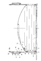
次に、図18に示すように脚付架台6を撤去し、タンク構成部材Yの下方を空間にする。そして、ジャッキアップ装置19によってタンク構成部材Yをジャッキダウンし、外槽屋根26の屋根骨12の外周端を外槽の側壁3の頂部内周面に埋設させた取付端29に連結し固定する。
続いて、外槽屋根26と内槽屋根14との間を連結する連結材(図示せず)を除去し、これらの間の連結を解除する。
続いて、外槽屋根26と内槽屋根14との間を連結する連結材(図示せず)を除去し、これらの間の連結を解除する。
次に、図19に示すようにジャッキアップ装置19によってタンク構成部材Yを再度ジャッキダウンし、内槽側板7の最下段の下端部をアニュラー部16上に降ろす。そして、内槽側板7の最下段の下端部を基礎版1に設置された内槽アンカーストラップ2に取り付ける。
次に、ナックルプレート9からナックルサポート10を除去し、さらに必要に応じてスペースキーパー11を除去する。
次に、ナックルプレート9からナックルサポート10を除去し、さらに必要に応じてスペースキーパー11を除去する。
その後、外槽の側壁3の緊張工事を行う。また、外槽の側壁3の内周面に貼設した側部ライナー(図示せず)に対して、冷熱抵抗緩和材であるポリウレタンフォーム(PUF)を吹きつける。さらに、ジャッキアップ装置19、第2の吊り架台25等も撤去する。そして、工事口4を閉鎖し、不図示のポンプバレルを設置し、水張りをして耐圧・気密試験を実施する。
最後に、内槽と外槽との間にパーライト等の保冷材(図示せず)を充填して内外槽間保冷工事を行う。塗装工事、配管保冷工事を行うと円筒型タンク100が完成する。
最後に、内槽と外槽との間にパーライト等の保冷材(図示せず)を充填して内外槽間保冷工事を行う。塗装工事、配管保冷工事を行うと円筒型タンク100が完成する。
このような構成の円筒型タンク100を構築するに際して、特に、ナックルプレート9に、外槽の側壁3及び懸垂足場5に干渉しないようにジャッキアップ装置用足場17(屋根上足場)を組み立てる。したがって、その後、ジャッキアップ装置用足場17を利用して、外槽の側壁3にジャッキアップ装置19を吊るための複数の吊り架台18を設ける工程や、吊り架台18とナックルサポート10との間にそれぞれジャッキアップ装置19を取り付ける工程などを容易に行うことができる。
したがって、本実施形態の円筒型タンクの構築方法によれば、特に外槽側壁3の一部を先に施工し、その後、外槽側壁3の残部の施工と内槽の施工とを並行して行う場合であっても、ナックルプレート9にジャッキアップ装置用足場17(屋根上足場)を組み立てるため、外槽の側壁3やその上部に形成された懸垂足場5に干渉されることなく、ジャッキアップ装置19の組み立てや吊り架台18の施工を容易にかつ効率的に行うことができる。これにより、工期を短縮し、コストを削減することができる。
また、ナックルプレート9の下側に内槽側板7を取り付けて金属製の内槽を組み立てる工程では、吊り架台18より上方に第2の吊り架台25を設けてジャッキアップ装置19を盛り替える処理が行われる。このような処理に際しても、ジャッキアップ装置用足場17を利用してジャッキアップ装置19の解体や側壁3からの吊り架台18の取り外しの作業を容易に行うことができる。
また、ジャッキアップ装置19によってナックルプレート9をジャッキアップ装置用足場17とともに吊り上げて上昇させた際、ジャッキアップロッド20の上端のロッド20bを下端側のロッド20bから取り外す処理を行う。このようなロッド20bの取り外しや取り外したロッド20bの内槽屋根14上への吊り降ろし等についても、ジャッキアップ装置用足場17を利用して容易に行うことができる。
また、ジャッキアップ装置用足場17に旋回可能なダビット15を設けているので、ジャッキアップロッド20の上端のロッド20bを下端側のロッド20bから取り外した際、ダビット15によって取り外したロッド20bを内槽屋根14上に容易に吊り降ろすことができる。
また、ジャッキアップ装置用足場17を複数のナックルサポート10に取り付けることにより、ジャッキアップ装置用足場17の少なくとも一部、本実施形態ではジャッキアップ装置用足場17のほぼ全体を複数のナックルサポート10に支持させる。したがって、ナックルプレート9へジャッキアップ装置用足場17を容易に取り付けることができる。また、ジャッキアップ装置用足場17の解体時には、ナックルプレート9に直接作業することなく、主にジャッキアップ装置用足場17とナックルサポート10との間における作業を行うのみで、ジャッキアップ装置用足場17をナックルプレート9から取り外すことができる。したがって、完成した円筒型タンク100の構成部材として残るナックルプレート9に、ジャッキアップ装置用足場17の解体によるダメージを与えることを防止することができる。
また、ナックルプレート9を組み立てる工程では、予め組み立てた内槽側板7の上側にナックルプレート9を取り付ける。高さ方向に湾曲しているナックルプレート9を最初に円環状に組み立てるより、高さ方向では湾曲していない内槽側板7を円環状に組み立て、その後ナックルプレート9を内槽側板7に取り付ける方が容易である。したがって、ナックルプレート9の組み立てを容易にすることができる。
また、特にジャッキアップ装置19によってタンク構成部材Yをジャッキアップさせている間、もしくは懸垂させている間に地震や強風等が起こると、内槽屋根14や外槽屋根26が外槽内で水平方向に大きく変位する可能性がある。しかしながら、ナックルサポート10、10間に、ナックルサポート10より外側(外槽の側壁3側)に位置するよう配置されるスペースキーパー11を設けているので、スペースキーパー11によって外槽の側壁3とナックルプレート9との間の実質的なクリアランスを小さくすることができる。したがって、地震等の影響によってナックルプレート9が水平方向に変位しても、その変位量を小さくすることができる。これによって、スペースキーパー11が外槽の側壁3に衝突した際の衝撃を緩和し、外槽の側壁3の損傷を防止することができる。また、ジャッキアップ装置19と被吊り板10bとの間が損傷することも確実に防止することができる。
以上、図面を参照しながら本発明の好適な実施形態について説明したが、本発明は前記実施形態に限定されるものではない。前述した実施形態において示した各構成部材の諸形状や組み合わせ等は一例であって、本発明の主旨から逸脱しない範囲において設計要求等に基づき種々変更可能である。
本発明によれば、ジャッキアップ装置の組み立てやジャッキアップ装置を保持するための架台等の施工を容易に行える円筒型タンクの構築方法を提供することができる。
3 外槽の側壁
5 懸垂足場
7 内槽側板
9 ナックルプレート(ナックル部)
10 ナックルサポート(被吊り部材)
14 内槽屋根
15 ダビット
17 ジャッキアップ装置用足場(屋根上足場)
18 吊り架台(吊り部)
19 ジャッキアップ装置
20 ジャッキアップロッド
20b ロッド
25 第2の吊り架台(第2の吊り部)
5 懸垂足場
7 内槽側板
9 ナックルプレート(ナックル部)
10 ナックルサポート(被吊り部材)
14 内槽屋根
15 ダビット
17 ジャッキアップ装置用足場(屋根上足場)
18 吊り架台(吊り部)
19 ジャッキアップ装置
20 ジャッキアップロッド
20b ロッド
25 第2の吊り架台(第2の吊り部)
Claims (6)
- 金属製の内槽とコンクリート製の外槽とを有する円筒型タンクの構築方法であって、
前記外槽の側壁を下段側から完成高さの途中まで施工する工程と、
前記外槽の前記側壁の内側にて円環状のナックル部を組み立てる工程と、
前記外槽の前記側壁の残りを、前記側壁に形成した懸垂足場を利用して施工する工程と、
前記ナックル部に、複数のジャッキアップ装置に連結する複数の被吊り部材を設ける工程と、
前記ナックル部に、前記外槽の前記側壁及び前記懸垂足場に干渉しない屋根上足場を組み立てる工程と、
前記外槽の前記側壁に、前記複数のジャッキアップ装置を吊るための複数の吊り部を設ける工程と、
前記外槽の前記側壁の前記複数の吊り部と前記ナックル部の前記複数の被吊り部材との間にそれぞれ前記複数のジャッキアップ装置を取り付ける工程と、
前記複数のジャッキアップ装置によって前記ナックル部を前記屋根上足場とともに吊り上げて上昇させ、上昇した前記ナックル部の下側に内槽側板を取り付けて前記内槽を組み立てる工程と、を備える円筒型タンクの構築方法。 - 前記内槽を組み立てる工程では、前記ナックル部の下側に一の内槽側板を取り付ける処理と、前記一の内槽側板の下に他の内槽側板を取り付ける処理との間に、前記外槽の前記側壁の前記複数の吊り部より上方に複数の第2の吊り部を設け、前記複数の第2の吊り部と前記複数の被吊り部材との間にそれぞれ前記複数のジャッキアップ装置を盛り替え、前記複数のジャッキアップ装置によって前記ナックル部をさらに上方に吊り上げて上昇させる処理を有する請求項1に記載の円筒型タンクの構築方法。
- 前記ジャッキアップ装置はジャッキ本体と前記ジャッキ本体に昇降可能に連結するジャッキアップロッドとを有し、前記ジャッキアップロッドは複数のロッドを長さ方向に着脱可能に連結することにより形成されており、
前記内槽を組み立てる工程では、前記複数のジャッキアップ装置によって前記ナックル部を前記屋根上足場とともに吊り上げて上昇させた際、前記ジャッキアップロッドの前記複数のロッドのうち、上端のロッドを下端側のロッドから取り外す処理を有する請求項1又は2に記載の円筒型タンクの構築方法。 - 前記屋根上足場に旋回可能なダビットが設けられる請求項3に記載の円筒型タンクの構築方法。
- 前記屋根上足場の少なくとも一部は前記複数の被吊り部材に連結され、前記複数の被吊り部材によって支持される請求項1~4のいずれか一項に記載の円筒型タンクの構築方法。
- 前記円環状のナックル部を組み立てる工程では、予め組み立てた円環状の内槽側板の上側に前記ナックル部を取り付けることにより前記ナックル部を組み立て、
前記内槽を組み立てる工程では、前記複数のジャッキアップ装置によって上昇させた前記ナックル部の下側の内槽側板に、次の内槽側板を取り付ける請求項1~5のいずれか一項に記載の円筒型タンクの構築方法。
Priority Applications (1)
| Application Number | Priority Date | Filing Date | Title |
|---|---|---|---|
| PH12015502355A PH12015502355A1 (en) | 2013-06-27 | 2015-10-09 | Method for constructing cylindrical tank |
Applications Claiming Priority (2)
| Application Number | Priority Date | Filing Date | Title |
|---|---|---|---|
| JP2013135164A JP6106540B2 (ja) | 2013-06-27 | 2013-06-27 | 円筒型タンクの構築方法 |
| JP2013-135164 | 2013-06-27 |
Publications (1)
| Publication Number | Publication Date |
|---|---|
| WO2014208672A1 true WO2014208672A1 (ja) | 2014-12-31 |
Family
ID=52141998
Family Applications (1)
| Application Number | Title | Priority Date | Filing Date |
|---|---|---|---|
| PCT/JP2014/067010 Ceased WO2014208672A1 (ja) | 2013-06-27 | 2014-06-26 | 円筒型タンクの構築方法 |
Country Status (4)
| Country | Link |
|---|---|
| JP (1) | JP6106540B2 (ja) |
| PH (1) | PH12015502355A1 (ja) |
| TW (1) | TWI537459B (ja) |
| WO (1) | WO2014208672A1 (ja) |
Cited By (1)
| Publication number | Priority date | Publication date | Assignee | Title |
|---|---|---|---|---|
| CN116714918A (zh) * | 2023-07-28 | 2023-09-08 | 张家港中集圣达因工程有限公司 | 薄膜罐 |
Families Citing this family (2)
| Publication number | Priority date | Publication date | Assignee | Title |
|---|---|---|---|---|
| JP6465488B2 (ja) * | 2015-09-11 | 2019-02-06 | 株式会社Ihi | 円筒型タンクの構築方法 |
| JP6461757B2 (ja) * | 2015-09-11 | 2019-01-30 | 株式会社Ihi | 円筒型タンクの構築方法 |
Citations (2)
| Publication number | Priority date | Publication date | Assignee | Title |
|---|---|---|---|---|
| JPS59142985A (ja) * | 1983-01-25 | 1984-08-16 | 石川島播磨重工業株式会社 | タンク屋根上の運搬装置 |
| WO2012137671A1 (ja) * | 2011-04-01 | 2012-10-11 | 株式会社Ihi | 円筒型タンクの構築方法 |
-
2013
- 2013-06-27 JP JP2013135164A patent/JP6106540B2/ja not_active Expired - Fee Related
-
2014
- 2014-06-26 WO PCT/JP2014/067010 patent/WO2014208672A1/ja not_active Ceased
- 2014-06-27 TW TW103122226A patent/TWI537459B/zh not_active IP Right Cessation
-
2015
- 2015-10-09 PH PH12015502355A patent/PH12015502355A1/en unknown
Patent Citations (2)
| Publication number | Priority date | Publication date | Assignee | Title |
|---|---|---|---|---|
| JPS59142985A (ja) * | 1983-01-25 | 1984-08-16 | 石川島播磨重工業株式会社 | タンク屋根上の運搬装置 |
| WO2012137671A1 (ja) * | 2011-04-01 | 2012-10-11 | 株式会社Ihi | 円筒型タンクの構築方法 |
Cited By (1)
| Publication number | Priority date | Publication date | Assignee | Title |
|---|---|---|---|---|
| CN116714918A (zh) * | 2023-07-28 | 2023-09-08 | 张家港中集圣达因工程有限公司 | 薄膜罐 |
Also Published As
| Publication number | Publication date |
|---|---|
| PH12015502355A1 (en) | 2016-02-22 |
| JP2015010361A (ja) | 2015-01-19 |
| TW201512504A (zh) | 2015-04-01 |
| JP6106540B2 (ja) | 2017-04-05 |
| TWI537459B (zh) | 2016-06-11 |
Similar Documents
| Publication | Publication Date | Title |
|---|---|---|
| US9546495B2 (en) | Method for constructing cylindrical tank | |
| TWI577866B (zh) | 圓筒型槽的建構方法 | |
| JP5732527B2 (ja) | 円筒型タンクの構築方法 | |
| JP2014095265A (ja) | 円筒型タンクの構築方法 | |
| JP6106539B2 (ja) | 円筒型タンクの構築方法 | |
| WO2014208672A1 (ja) | 円筒型タンクの構築方法 | |
| JP6319869B2 (ja) | 円筒型タンクの構築方法 | |
| TWI502119B (zh) | 圓筒型儲槽之構築方法 | |
| TWI498470B (zh) | 圓筒型儲槽之構築方法 | |
| JP6351173B2 (ja) | 円筒型タンクの構築方法 | |
| JP6351174B2 (ja) | 円筒型タンクの構築方法 | |
| JP6663204B2 (ja) | 円筒型タンクの構築方法 | |
| JP2016098514A (ja) | 円筒型タンクの構築方法 | |
| JP2016098512A (ja) | 円筒型タンクの構築方法 | |
| TWI620861B (zh) | 圓筒型槽之建構方法 | |
| JP2016098513A (ja) | 円筒型タンクの構築方法 | |
| JP2016098508A (ja) | 円筒型タンクの構築方法 |
Legal Events
| Date | Code | Title | Description |
|---|---|---|---|
| 121 | Ep: the epo has been informed by wipo that ep was designated in this application |
Ref document number: 14817803 Country of ref document: EP Kind code of ref document: A1 |
|
| WWE | Wipo information: entry into national phase |
Ref document number: 12015502355 Country of ref document: PH |
|
| NENP | Non-entry into the national phase |
Ref country code: DE |
|
| 122 | Ep: pct application non-entry in european phase |
Ref document number: 14817803 Country of ref document: EP Kind code of ref document: A1 |