WO2014208408A1 - 熱伝導性シート、及びその製造方法、並びに半導体装置 - Google Patents
熱伝導性シート、及びその製造方法、並びに半導体装置 Download PDFInfo
- Publication number
- WO2014208408A1 WO2014208408A1 PCT/JP2014/066095 JP2014066095W WO2014208408A1 WO 2014208408 A1 WO2014208408 A1 WO 2014208408A1 JP 2014066095 W JP2014066095 W JP 2014066095W WO 2014208408 A1 WO2014208408 A1 WO 2014208408A1
- Authority
- WO
- WIPO (PCT)
- Prior art keywords
- conductive sheet
- heat conductive
- heat
- carbon fiber
- inorganic filler
- Prior art date
- Legal status (The legal status is an assumption and is not a legal conclusion. Google has not performed a legal analysis and makes no representation as to the accuracy of the status listed.)
- Ceased
Links
Images



Classifications
-
- H—ELECTRICITY
- H10—SEMICONDUCTOR DEVICES; ELECTRIC SOLID-STATE DEVICES NOT OTHERWISE PROVIDED FOR
- H10W—GENERIC PACKAGES, INTERCONNECTIONS, CONNECTORS OR OTHER CONSTRUCTIONAL DETAILS OF DEVICES COVERED BY CLASS H10
- H10W40/00—Arrangements for thermal protection or thermal control
- H10W40/20—Arrangements for cooling
- H10W40/25—Arrangements for cooling characterised by their materials
- H10W40/251—Organics
-
- B—PERFORMING OPERATIONS; TRANSPORTING
- B29—WORKING OF PLASTICS; WORKING OF SUBSTANCES IN A PLASTIC STATE IN GENERAL
- B29C—SHAPING OR JOINING OF PLASTICS; SHAPING OF MATERIAL IN A PLASTIC STATE, NOT OTHERWISE PROVIDED FOR; AFTER-TREATMENT OF THE SHAPED PRODUCTS, e.g. REPAIRING
- B29C48/00—Extrusion moulding, i.e. expressing the moulding material through a die or nozzle which imparts the desired form; Apparatus therefor
- B29C48/001—Combinations of extrusion moulding with other shaping operations
- B29C48/0022—Combinations of extrusion moulding with other shaping operations combined with cutting
-
- B—PERFORMING OPERATIONS; TRANSPORTING
- B29—WORKING OF PLASTICS; WORKING OF SUBSTANCES IN A PLASTIC STATE IN GENERAL
- B29C—SHAPING OR JOINING OF PLASTICS; SHAPING OF MATERIAL IN A PLASTIC STATE, NOT OTHERWISE PROVIDED FOR; AFTER-TREATMENT OF THE SHAPED PRODUCTS, e.g. REPAIRING
- B29C48/00—Extrusion moulding, i.e. expressing the moulding material through a die or nozzle which imparts the desired form; Apparatus therefor
- B29C48/022—Extrusion moulding, i.e. expressing the moulding material through a die or nozzle which imparts the desired form; Apparatus therefor characterised by the choice of material
-
- B—PERFORMING OPERATIONS; TRANSPORTING
- B29—WORKING OF PLASTICS; WORKING OF SUBSTANCES IN A PLASTIC STATE IN GENERAL
- B29C—SHAPING OR JOINING OF PLASTICS; SHAPING OF MATERIAL IN A PLASTIC STATE, NOT OTHERWISE PROVIDED FOR; AFTER-TREATMENT OF THE SHAPED PRODUCTS, e.g. REPAIRING
- B29C48/00—Extrusion moulding, i.e. expressing the moulding material through a die or nozzle which imparts the desired form; Apparatus therefor
- B29C48/03—Extrusion moulding, i.e. expressing the moulding material through a die or nozzle which imparts the desired form; Apparatus therefor characterised by the shape of the extruded material at extrusion
- B29C48/07—Flat, e.g. panels
-
- B—PERFORMING OPERATIONS; TRANSPORTING
- B29—WORKING OF PLASTICS; WORKING OF SUBSTANCES IN A PLASTIC STATE IN GENERAL
- B29C—SHAPING OR JOINING OF PLASTICS; SHAPING OF MATERIAL IN A PLASTIC STATE, NOT OTHERWISE PROVIDED FOR; AFTER-TREATMENT OF THE SHAPED PRODUCTS, e.g. REPAIRING
- B29C48/00—Extrusion moulding, i.e. expressing the moulding material through a die or nozzle which imparts the desired form; Apparatus therefor
- B29C48/03—Extrusion moulding, i.e. expressing the moulding material through a die or nozzle which imparts the desired form; Apparatus therefor characterised by the shape of the extruded material at extrusion
- B29C48/07—Flat, e.g. panels
- B29C48/08—Flat, e.g. panels flexible, e.g. films
-
- B—PERFORMING OPERATIONS; TRANSPORTING
- B29—WORKING OF PLASTICS; WORKING OF SUBSTANCES IN A PLASTIC STATE IN GENERAL
- B29C—SHAPING OR JOINING OF PLASTICS; SHAPING OF MATERIAL IN A PLASTIC STATE, NOT OTHERWISE PROVIDED FOR; AFTER-TREATMENT OF THE SHAPED PRODUCTS, e.g. REPAIRING
- B29C48/00—Extrusion moulding, i.e. expressing the moulding material through a die or nozzle which imparts the desired form; Apparatus therefor
- B29C48/25—Component parts, details or accessories; Auxiliary operations
- B29C48/88—Thermal treatment of the stream of extruded material, e.g. cooling
- B29C48/91—Heating, e.g. for cross linking
-
- C—CHEMISTRY; METALLURGY
- C09—DYES; PAINTS; POLISHES; NATURAL RESINS; ADHESIVES; COMPOSITIONS NOT OTHERWISE PROVIDED FOR; APPLICATIONS OF MATERIALS NOT OTHERWISE PROVIDED FOR
- C09K—MATERIALS FOR MISCELLANEOUS APPLICATIONS, NOT PROVIDED FOR ELSEWHERE
- C09K5/00—Heat-transfer, heat-exchange or heat-storage materials, e.g. refrigerants; Materials for the production of heat or cold by chemical reactions other than by combustion
- C09K5/08—Materials not undergoing a change of physical state when used
- C09K5/14—Solid materials, e.g. powdery or granular
-
- H—ELECTRICITY
- H10—SEMICONDUCTOR DEVICES; ELECTRIC SOLID-STATE DEVICES NOT OTHERWISE PROVIDED FOR
- H10W—GENERIC PACKAGES, INTERCONNECTIONS, CONNECTORS OR OTHER CONSTRUCTIONAL DETAILS OF DEVICES COVERED BY CLASS H10
- H10W40/00—Arrangements for thermal protection or thermal control
- H10W40/20—Arrangements for cooling
- H10W40/25—Arrangements for cooling characterised by their materials
-
- H—ELECTRICITY
- H10—SEMICONDUCTOR DEVICES; ELECTRIC SOLID-STATE DEVICES NOT OTHERWISE PROVIDED FOR
- H10W—GENERIC PACKAGES, INTERCONNECTIONS, CONNECTORS OR OTHER CONSTRUCTIONAL DETAILS OF DEVICES COVERED BY CLASS H10
- H10W40/00—Arrangements for thermal protection or thermal control
- H10W40/20—Arrangements for cooling
- H10W40/25—Arrangements for cooling characterised by their materials
- H10W40/257—Arrangements for cooling characterised by their materials having a heterogeneous or anisotropic structure, e.g. powder or fibres in a matrix, wire mesh or porous structures
-
- H—ELECTRICITY
- H10—SEMICONDUCTOR DEVICES; ELECTRIC SOLID-STATE DEVICES NOT OTHERWISE PROVIDED FOR
- H10W—GENERIC PACKAGES, INTERCONNECTIONS, CONNECTORS OR OTHER CONSTRUCTIONAL DETAILS OF DEVICES COVERED BY CLASS H10
- H10W70/00—Package substrates; Interposers; Redistribution layers [RDL]
- H10W70/01—Manufacture or treatment
- H10W70/02—Manufacture or treatment of conductive package substrates serving as an interconnection, e.g. of metal plates
-
- B—PERFORMING OPERATIONS; TRANSPORTING
- B29—WORKING OF PLASTICS; WORKING OF SUBSTANCES IN A PLASTIC STATE IN GENERAL
- B29C—SHAPING OR JOINING OF PLASTICS; SHAPING OF MATERIAL IN A PLASTIC STATE, NOT OTHERWISE PROVIDED FOR; AFTER-TREATMENT OF THE SHAPED PRODUCTS, e.g. REPAIRING
- B29C35/00—Heating, cooling or curing, e.g. crosslinking or vulcanising; Apparatus therefor
- B29C35/02—Heating or curing, e.g. crosslinking or vulcanizing during moulding, e.g. in a mould
- B29C35/08—Heating or curing, e.g. crosslinking or vulcanizing during moulding, e.g. in a mould by wave energy or particle radiation
- B29C35/0805—Heating or curing, e.g. crosslinking or vulcanizing during moulding, e.g. in a mould by wave energy or particle radiation using electromagnetic radiation
- B29C2035/0822—Heating or curing, e.g. crosslinking or vulcanizing during moulding, e.g. in a mould by wave energy or particle radiation using electromagnetic radiation using IR radiation
-
- B—PERFORMING OPERATIONS; TRANSPORTING
- B29—WORKING OF PLASTICS; WORKING OF SUBSTANCES IN A PLASTIC STATE IN GENERAL
- B29K—INDEXING SCHEME ASSOCIATED WITH SUBCLASSES B29B, B29C OR B29D, RELATING TO MOULDING MATERIALS OR TO MATERIALS FOR MOULDS, REINFORCEMENTS, FILLERS OR PREFORMED PARTS, e.g. INSERTS
- B29K2995/00—Properties of moulding materials, reinforcements, fillers, preformed parts or moulds
- B29K2995/0012—Properties of moulding materials, reinforcements, fillers, preformed parts or moulds having particular thermal properties
- B29K2995/0013—Conductive
Definitions
- the present invention relates to a heat conductive sheet, a manufacturing method thereof, and a semiconductor device.
- the semiconductor element is attached to a heat sink such as a heat radiating fin or a heat radiating plate via a heat conductive sheet in order to efficiently dissipate heat.
- a thermally conductive sheet a material in which a filler (thermally conductive filler) such as an inorganic filler is dispersed in silicone is widely used.
- the inorganic filler include alumina, aluminum nitride, and aluminum hydroxide.
- carbon fiber has a thermal conductivity of about 600 W / m ⁇ K to 1,200 W / m ⁇ K in the fiber direction.
- Boron nitride is known to have anisotropy in the plane direction of about 110 W / m ⁇ K and in the direction perpendicular to the plane direction of about 2 W / m ⁇ K.
- thermal conductivity is required to be obtained with a thin sheet.
- a heat conductive sheet having both excellent high heat conductivity and flexibility can be obtained (for example, see Patent Document 3).
- a thermal conductive sheet having a small thickness for example, an average thickness of 500 ⁇ m or less
- a thermal conductive sheet capable of achieving both excellent high thermal conductivity and excellent flexibility required in recent years is obtained. It is not done.
- thermally conductive sheet that can achieve both excellent high thermal conductivity and excellent flexibility even when the thickness is thin, a manufacturing method thereof, and a semiconductor device using the thermal conductive sheet.
- the current situation is.
- the present invention provides a thermally conductive sheet that can achieve both excellent high thermal conductivity and excellent flexibility even when the thickness is thin, a manufacturing method thereof, and a semiconductor device using the thermally conductive sheet.
- the purpose is to do.
- a heat conductive sheet sandwiched between a heat source of a semiconductor device and a heat dissipation member Contains a binder, carbon fiber, and inorganic filler,
- the carbon fiber has an average fiber length of 50 ⁇ m to 250 ⁇ m;
- the thermal resistance under a load of 7.5 kgf / cm 2 measured in accordance with ASTM-D5470 is less than 0.17 K ⁇ cm 2 / W,
- the heat conductive sheet is characterized in that an average thickness of the heat conductive sheet is 500 ⁇ m or less.
- the thermal resistance is less than or equal to 0.20K ⁇ cm 2 / W ⁇ 1>.
- a part of the carbon fiber is arranged on the surface of the heat conductive sheet, and the long axis of the carbon fiber is arranged along the surface direction of the heat conductive sheet. It is a heat conductive sheet in any one.
- ⁇ 5> The thermal conductive sheet according to ⁇ 4>, wherein the average particle diameter of alumina is 1 ⁇ m to 5 ⁇ m.
- ⁇ 6> The thermal conductive sheet according to any one of ⁇ 1> to ⁇ 5>, wherein the inorganic filler contains aluminum nitride.
- ⁇ 7> The heat conductive sheet according to any one of ⁇ 1> to ⁇ 6>, wherein the carbon fiber content is 20% by volume to 40% by volume.
- ⁇ 8> The heat conductive sheet according to any one of ⁇ 1> to ⁇ 7>, wherein the content of the inorganic filler is 30% by volume to 55% by volume.
- thermo conductive sheet according to any one of ⁇ 1> to ⁇ 8>, wherein an average thickness ( ⁇ m) of the thermal conductive sheet is larger than an average fiber length ( ⁇ m) of the carbon fiber.
- the conventional problems can be solved, the object can be achieved, and even if the thickness is thin, a thermal conductive sheet that can achieve both excellent high thermal conductivity and excellent flexibility, And the manufacturing method of the same, and the semiconductor device using the said heat conductive sheet can be provided.
- FIG. 1A is a schematic diagram showing the orientation of carbon fibers during extrusion molding.
- FIG. 1B is a schematic diagram showing the orientation of carbon fibers during extrusion molding.
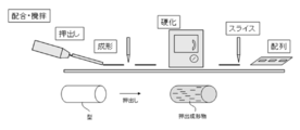
- FIG. 2 is a schematic view for explaining an example of a method for producing a thermally conductive sheet of the present invention.
- FIG. 3 is a schematic cross-sectional view showing an example of the semiconductor device of the present invention.
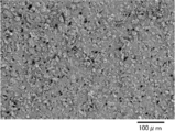
- 4 is an SEM photograph of the surface of the thermally conductive sheet of Example 1.
- FIG. 1A is a schematic diagram showing the orientation of carbon fibers during extrusion molding.
- FIG. 1B is a schematic diagram showing the orientation of carbon fibers during extrusion molding.
- FIG. 2 is a schematic view for explaining an example of a method for producing a thermally conductive sheet of the present invention.
- FIG. 3 is
- the heat conductive sheet of this invention contains a binder, carbon fiber, and an inorganic filler at least, and also contains another component as needed.
- the thermally conductive sheet is used by being sandwiched between a heat source of a semiconductor device and a heat radiating member.
- binder resin examples include thermoplastic polymers and cured products of thermosetting polymers.
- thermoplastic polymer examples include thermoplastic resins, thermoplastic elastomers, and polymer alloys thereof.
- thermoplastic resin is not particularly limited and may be appropriately selected depending on the intended purpose.
- thermoplastic elastomer examples include styrene-based thermoplastic elastomers, olefin-based thermoplastic elastomers, vinyl chloride-based thermoplastic elastomers, polyester-based thermoplastic elastomers, polyurethane-based thermoplastic elastomers, and polyamide-based thermoplastic elastomers. These may be used individually by 1 type and may use 2 or more types together.
- thermosetting polymer examples include crosslinked rubber, epoxy resin, polyimide resin, bismaleimide resin, benzocyclobutene resin, phenol resin, unsaturated polyester, diallyl phthalate resin, silicone resin, polyurethane, polyimide silicone, thermosetting type.
- examples thereof include polyphenylene ether and thermosetting modified polyphenylene ether. These may be used individually by 1 type and may use 2 or more types together.
- crosslinked rubber examples include natural rubber, butadiene rubber, isoprene rubber, nitrile rubber, hydrogenated nitrile rubber, chloroprene rubber, ethylene propylene rubber, chlorinated polyethylene, chlorosulfonated polyethylene, butyl rubber, halogenated butyl rubber, fluorine rubber, Examples thereof include urethane rubber, acrylic rubber, polyisobutylene rubber, and silicone rubber. These may be used individually by 1 type and may use 2 or more types together.
- thermosetting polymer is a silicone resin from the viewpoints of excellent moldability and weather resistance, and adhesion and followability to electronic components.
- the silicone resin is not particularly limited and may be appropriately selected depending on the intended purpose. Examples thereof include addition reaction type liquid silicone resin, heat vulcanization type millable type silicone resin using peroxide for vulcanization, and the like. Can be mentioned. Among these, an addition reaction type liquid silicone resin is particularly preferable as a heat radiating member of an electronic device because adhesion between a heat generating surface of an electronic component and a heat sink surface is required.
- the addition reaction type liquid silicone resin is preferably a two-component addition reaction type silicone resin in which a polyorganosiloxane having a vinyl group is liquid A and a polyorganosiloxane having a Si—H group is liquid B.
- the mixing ratio of the liquid A and the liquid B is appropriately selected depending on the desired flexibility of the heat conductive sheet.
- the content of the binder in the thermally conductive sheet is not particularly limited and may be appropriately selected depending on the intended purpose, but is preferably 25% by volume to 50% by volume.
- the carbon fiber is not particularly limited as long as the average fiber length (average major axis length) is 50 ⁇ m to 250 ⁇ m, and can be appropriately selected according to the purpose.
- the average fiber length (average major axis length) is 50 ⁇ m to 250 ⁇ m, and can be appropriately selected according to the purpose.
- pitch PAN, arc
- Those synthesized by a discharge method, a laser evaporation method, a CVD method (chemical vapor deposition method), a CCVD method (catalytic chemical vapor deposition method), or the like can be used.
- pitch-based carbon fibers are particularly preferable from the viewpoint of thermal conductivity.
- the carbon fiber can be used by partially or entirely treating the carbon fiber.
- Examples of the surface treatment include oxidation treatment, nitriding treatment, nitration, sulfonation, or attaching a metal, a metal compound, an organic compound, or the like to the surface of a functional group or carbon fiber introduced to the surface by these treatments.
- the process etc. which are combined are mentioned.
- Examples of the functional group include a hydroxyl group, a carboxyl group, a carbonyl group, a nitro group, and an amino group.
- a part of the carbon fiber is arranged on the surface of the heat conductive sheet and the long axis of the carbon fiber is arranged along the surface direction of the heat conductive sheet from the viewpoint of reducing the heat resistance.
- the average fiber length (average major axis length) of the carbon fiber is 50 ⁇ m to 250 ⁇ m, preferably 75 ⁇ m to 200 ⁇ m, and more preferably 100 ⁇ m to 150 ⁇ m. If the average fiber length is less than 50 ⁇ m, sufficient anisotropic thermal conductivity cannot be obtained, resulting in high thermal resistance. When the average fiber length exceeds 250 ⁇ m, the compressibility of the heat conductive sheet is lowered, and a sufficiently low heat resistance cannot be obtained during use.
- the average short axis length of the carbon fiber is not particularly limited and may be appropriately selected depending on the intended purpose, but is preferably 6 ⁇ m to 15 ⁇ m, and more preferably 8 ⁇ m to 13 ⁇ m.
- the aspect ratio (average major axis length / average minor axis length) of the carbon fiber is not particularly limited and may be appropriately selected depending on the intended purpose, but is preferably 8 or more, more preferably 12 to 30. . When the aspect ratio is less than 8, since the fiber length (major axis length) of the carbon fiber is short, the thermal conductivity may be lowered.
- the average major axis length and the average minor axis length of the carbon fiber can be measured, for example, with a microscope, a scanning electron microscope (SEM), or the like.
- the content of the carbon fiber in the thermally conductive sheet is not particularly limited and may be appropriately selected depending on the intended purpose, but is preferably 20% by volume to 40% by volume, and 22% by volume to 36% by volume. More preferred is 28 to 36% by volume.
- the content is less than 20% by volume, it may be difficult to obtain a sufficiently low thermal resistance.
- the content exceeds 40% by volume, the moldability of the thermally conductive sheet and the orientation of the carbon fibers may be obtained. May affect sex.
- ⁇ Inorganic filler> There is no restriction
- the inorganic filler is different from the carbon fiber.
- the inorganic filler examples include aluminum nitride (aluminum nitride: AlN), silica, alumina (aluminum oxide), boron nitride, titania, glass, zinc oxide, silicon carbide, silicon (silicon), silicon oxide, aluminum oxide, and metal. And particles. These may be used individually by 1 type and may use 2 or more types together. Among these, alumina, boron nitride, aluminum nitride, zinc oxide, and silica are preferable, and alumina and aluminum nitride are particularly preferable from the viewpoint of thermal conductivity.
- the inorganic filler may be subjected to a surface treatment.
- the inorganic filler is treated with a coupling agent as the surface treatment, the dispersibility of the inorganic filler is improved, and the flexibility of the heat conductive sheet is improved.
- the average particle size of the said inorganic filler is preferably 1 ⁇ m to 10 ⁇ m, more preferably 1 ⁇ m to 5 ⁇ m, and particularly preferably 4 ⁇ m to 5 ⁇ m.
- the average particle size is less than 1 ⁇ m, the viscosity increases and mixing may be difficult.
- the average particle size exceeds 10 ⁇ m, the thermal resistance of the thermally conductive sheet may increase.
- the average particle size is preferably 0.3 ⁇ m to 6.0 ⁇ m, more preferably 0.3 ⁇ m to 2.0 ⁇ m, and particularly preferably 0.5 ⁇ m to 1.5 ⁇ m. If the average particle size is less than 0.3 ⁇ m, the viscosity may increase and mixing may be difficult, and if it exceeds 6.0 ⁇ m, the thermal resistance of the thermally conductive sheet may increase.
- the average particle diameter of the inorganic filler can be measured by, for example, a particle size distribution meter or a scanning electron microscope (SEM).
- the inorganic filler is alumina, its specific surface area, 0.3m 2 /g ⁇ 0.9m 2 / g are preferred.
- the specific surface area is preferably 1 m 2 / g to 3 m 2 / g.
- the specific surface area of the inorganic filler can be measured by, for example, the BET method.
- the content of the inorganic filler in the thermally conductive sheet is not particularly limited and may be appropriately selected depending on the intended purpose, but is preferably 30% by volume to 55% by volume, and 35% by volume to 50% by volume. More preferred. When the content is less than 30% by volume, the thermal resistance of the thermally conductive sheet may increase, and when it exceeds 55% by volume, the flexibility of the thermally conductive sheet may be reduced.
- the other components are not particularly limited and may be appropriately selected depending on the intended purpose. Examples thereof include thixotropic agents, dispersants, curing accelerators, retarders, slightly tackifiers, plasticizers, and flame retardants. , Antioxidants, stabilizers, colorants and the like.
- the average thickness of the heat conductive sheet is 500 ⁇ m or less, preferably 100 ⁇ m to 400 ⁇ m, and more preferably 200 ⁇ m to 350 ⁇ m.
- the average thickness is an average thickness when no load is applied.
- the average thickness ( ⁇ m) of the thermal conductive sheet is preferably larger than the average fiber length ( ⁇ m) of the carbon fiber. By doing so, it is easy to compress during use and a sufficiently low thermal resistance is obtained.
- the heat conductive sheet preferably has a compressibility of 5% or more, more preferably 10% to 70%, when a load of 7.5 kgf / cm 2 is applied. If the compression ratio is less than 5%, the thermal resistance may not be reduced during compression.
- the thermal conductive sheet has a thermal resistance of less than 0.17 K ⁇ cm 2 / W measured under a load of 7.5 kgf / cm 2 as measured according to ASTM-D5470.
- a load 7.5 kgf / cm 2 as measured according to ASTM-D5470.
- 0.04K * cm ⁇ 2 > / W is preferable.
- the reason why the thermal resistance is measured by applying a load is that, in use, the thermal conductive sheet is usually loaded by being sandwiched between the heat source of the semiconductor device and the heat radiating member.
- the thermal resistance changes.
- the thermally conductive sheet is in a range of load 2.0 kgf / cm 2 ⁇ load 7.5 kgf / cm 2 when measuring thermal resistance according to ASTM-D5470, thermal resistance, 0.20K ⁇ cm 2 / W or less It is preferable that By doing so, it is advantageous in that a thermally conductive sheet having a very excellent thermal resistance can be obtained regardless of the use environment.
- thermally conductive sheet having a very excellent thermal resistance can be obtained regardless of the use environment.
- limiting in particular as a lower limit of the said heat resistance Although it can select suitably according to the objective, 0.04K * cm ⁇ 2 > / W is preferable.
- the method for producing the heat conductive sheet is not particularly limited and may be appropriately selected depending on the intended purpose. However, the method for producing a heat conductive sheet of the present invention described below is preferable.
- the manufacturing method of a heat conductive sheet of this invention includes an extrusion process, a hardening process, and a cutting process at least, and also includes another process as needed.
- the extrusion molding step is not particularly limited as long as it is a step of extruding the thermally conductive composition with an extruder to obtain an extrusion molded product, and can be appropriately selected according to the purpose.
- the said heat conductive composition contains a binder precursor, carbon fiber, and an inorganic filler, and also contains another component as needed.
- the binder precursor is a precursor of the binder that is cured by a curing process to be described later to become a binder of the thermally conductive sheet.
- examples thereof include curable polymers.
- the carbon fiber is the carbon fiber exemplified in the description of the thermally conductive sheet of the present invention.
- the said inorganic filler is the said inorganic filler illustrated in description of the said heat conductive sheet of this invention.
- the heat conductive composition can be prepared by mixing the binder precursor, the carbon fiber, the inorganic filler, and, if necessary, other components using a mixer or the like.
- An extruded product can be obtained by extruding the thermally conductive composition into a mold using an extruder.
- the extrusion port of the extruder is usually provided with a plurality of slits, whereby the carbon fibers are oriented in the extrusion direction.
- the shape and size of the slit are not particularly limited and may be appropriately selected according to the purpose. Examples of the shape of the slit include a flat plate shape, a lattice shape, and a honeycomb shape.
- the size (width) of the slit is not particularly limited and may be appropriately selected depending on the intended purpose, but is preferably 0.5 mm to 10 mm.
- rate of the said heat conductive composition Although it can select suitably according to the objective, 0.001 L / min or more is preferable.
- the shape, size, material, and the like of the mold are not particularly limited and can be appropriately selected according to the purpose.
- Examples of the shape include a hollow columnar shape and a hollow prismatic shape.
- size it can select suitably according to the magnitude
- Examples of the material include stainless steel.
- the carbon fiber, the inorganic filler, and the like are collected in the center direction of the thermally conductive composition, and the carbon fiber is formed between the surface and the center of the extruded product.
- the density of the inorganic filler is different. That is, since the carbon fiber and the inorganic filler do not protrude from the surface of the thermally conductive composition (molded body) that has passed through the extruder, the cured thermal conductive composition (molded body) is cured.
- the surface portion of the object (the outer peripheral portion of the heat conductive sheet) has good fine tackiness, and the adhesion to an adherend (semiconductor device or the like) is good.
- carbon fiber can be orientated in an extrusion direction by extruding the heat conductive composition containing the carbon fiber 11 and the inorganic filler 12.
- the slightly sticky means that it has removability with little increase in adhesive force due to aging and wet heat, and has a stickiness that does not easily shift when it is attached to an adherend.
- the curing step is a step of curing the extrusion-molded product to obtain a cured product.
- the extrusion-molded product molded in the extrusion molding step becomes a cured product by an appropriate curing reaction according to the binder precursor to be used.
- the method for curing the extruded product is not particularly limited and may be appropriately selected depending on the intended purpose. However, when a thermosetting polymer such as a silicone resin is used as the binder precursor, it is cured by heating. It is preferable. Examples of the apparatus used for the heating include a far infrared furnace and a hot air furnace. The heating temperature is not particularly limited and may be appropriately selected depending on the intended purpose, but is preferably performed at 40 ° C. to 150 ° C.
- the flexibility of the silicone cured product obtained by curing the silicone resin is not particularly limited. However, it can be appropriately selected according to the purpose, and can be adjusted by, for example, the crosslinking density of the silicone cured product, the filling amount of the carbon fiber, the filling amount of the inorganic filler, and the like.
- the cutting step is not particularly limited as long as it is a step of cutting the cured product to an average thickness of 500 ⁇ m or less in a direction perpendicular to the direction of extrusion, and can be appropriately selected according to the purpose.
- the cutting is performed using, for example, an ultrasonic cutter or a planer.
- the transmission frequency and amplitude can be adjusted, and it is preferable to adjust the transmission frequency in the range of 10 kHz to 100 kHz and the amplitude in the range of 10 ⁇ m to 100 ⁇ m. If the cutting is performed with a cutter knife or meat slicer (rotating blade) instead of an ultrasonic cutter, the surface roughness Ra of the cut surface increases and the thermal resistance increases.
- the carbon fiber is oriented in the thickness direction of the thermally conductive sheet (vertical orientation) by cutting the cured product having undergone the curing reaction into a predetermined thickness in a direction perpendicular to the direction of extrusion.
- a thermally conductive sheet thus obtained can be obtained.
- a part of the carbon fiber adheres to the surface of the heat conductive sheet, and the long axis of the carbon fiber adheres along the surface direction of the heat conductive sheet, thereby along the surface direction of the heat conductive sheet.
- a thermally conductive sheet having the arranged carbon fibers on the surface of the thermally conductive sheet can be obtained.
- a heat conductive sheet is manufactured through a series of processes such as extrusion, molding, curing, and cutting (slicing).
- a heat conductive composition is prepared by blending and stirring a binder precursor, carbon fiber, and an inorganic filler.
- the carbon fibers blended in the thermally conductive composition are oriented in the thickness direction of the thermally conductive sheet by passing through a plurality of slits.
- the cured product is cut (sliced) to a predetermined thickness with an ultrasonic cutter in a direction perpendicular to the extrusion direction, whereby a heat conductive sheet can be produced.
- the semiconductor device of the present invention includes a heat dissipation member, a heat source, and a heat conductive sheet, and further includes other members as necessary.
- the thermally conductive sheet is sandwiched between the heat source and the heat radiating member.
- Heat source> There is no restriction
- the heat radiating member is not particularly limited as long as heat generated from the semiconductor element is conducted and dissipated to the outside, and can be appropriately selected according to the purpose.
- a heat radiating device a cooler, a heat sink , Heat spreader, die pad, printed circuit board, cooling fan, Peltier element, heat pipe, housing, and the like.
- the heat conductive sheet is the heat conductive sheet of the present invention.
- FIG. 3 is a schematic view showing an example of the semiconductor device 10, in which the semiconductor element 2 is disposed on the substrate 1, and the heat conductive sheet 3 is sandwiched between the heat radiating member 4. Yes.
- the average particle diameters of alumina particles and aluminum nitride are values measured by a particle size distribution meter.
- the average major axis length and the average minor axis length of the pitch-based carbon fibers are values measured with a microscope (manufactured by HiROX Co Ltd, KH7700).
- Example 1 -Production of thermal conductive sheet- Silicone A liquid (organopolysiloxane having vinyl group) and Silicone B liquid (organopolysiloxane having H-Si group) mixed at a mass ratio of 3: 7 (A liquid: B liquid) Alumina (average particle size 4 ⁇ m, spherical, specific surface area 0.3 m 2 / g, manufactured by Nippon Steel & Sumikin Materials Co., Ltd., Micron), 18% by volume, classified into addition reaction type liquid silicone resin to adjust specific surface area, nitriding 21% by volume of aluminum (average particle size 1 ⁇ m, spherical, specific surface area 3 m 2 / g, H grade, manufactured by Tokuyama Corporation), pitch-based carbon fiber (average fiber length 100 ⁇ m, average minor axis length 9.2 ⁇ m, XN100- 10M, manufactured by Nippon Graphite Fiber Co., Ltd.) was dispersed to prepare a silicone resin composition.
- a liquid organ
- blending is the volume% in the heat conductive sheet obtained.
- Alumina and aluminum nitride used were subjected to coupling treatment with a silane coupling agent.
- the obtained silicone resin composition was extruded into a mold (hollow cylindrical shape) with an extruder to produce a silicone molded body.
- a slit discharge port shape: flat plate) is formed in the extrusion port of the extruder.
- the obtained silicone molded body was heated in an oven at 100 ° C. for 6 hours to obtain a cured silicone product.
- the obtained silicone cured product was sliced and cut perpendicularly to the direction of extrusion with an ultrasonic cutter so that the average thickness was 100 ⁇ m (transmitting frequency 20.5 kHz, amplitude 50 ⁇ m to 70 ⁇ m).
- a square-shaped thermally conductive sheet of Example 1 having an average thickness of 100 ⁇ m, a length of 30 mm, and a width of 30 mm was produced.
- the pitch-based carbon fibers were oriented at 0 to 5 degrees with respect to the thickness direction of the heat conductive sheet. It was.
- FIG. 4 the SEM photograph of the surface of a heat conductive sheet was shown.
- the compression rate of the obtained heat conductive sheet was measured. The results are shown in Table 5-1.
- Example 1 (Examples 2 to 15, Comparative Examples 1 to 4)
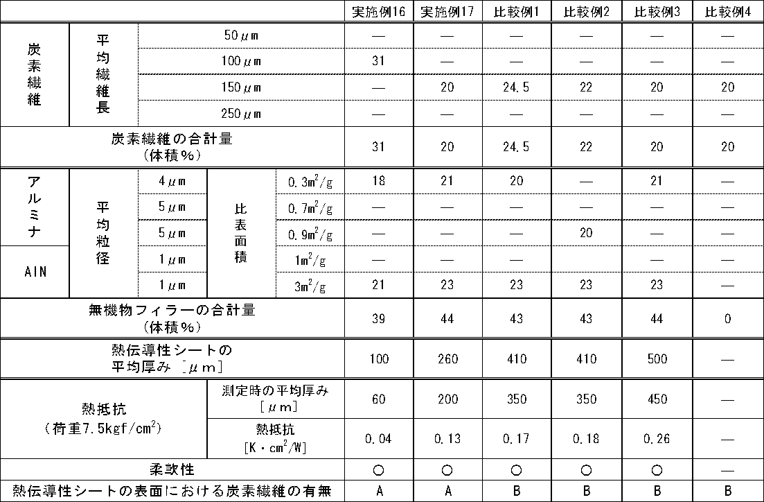
- Example 1 the types and amounts of carbon fibers (volume%), the types and amounts of alumina (volume%), the types and amounts of aluminum nitride (volume%), and the average thickness of the heat conductive sheet are shown in Table 1 to 3 except that the carbon fiber type and amount (% by volume), the type and amount of alumina (volume%), the type and amount of aluminum nitride (% by volume), and the average thickness of the heat conductive sheet are changed.
- a heat conductive sheet was produced in the same manner as in Example 1.
- the obtained heat conductive sheet was evaluated in the same manner as in Example 1.
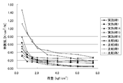
- the results are shown in Tables 1 to 4 and FIG.
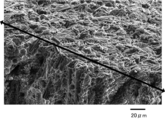
- Example 16 In Example 1, the heat conductive sheet was produced like Example 1 except having changed the compounding ratio (mass ratio) of silicone A liquid and silicone B liquid into 5: 5. The obtained heat conductive sheet was evaluated in the same manner as in Example 1. The results are shown in Table 3 and FIG. Moreover, the compression rate in each load was measured. The measurement results are shown in Table 5-1. Furthermore, the SEM photograph of the heat conductive sheet is shown in FIG. Here, the part above the arrow on the SEM photograph shows the surface of the heat conductive sheet, and the lower part shows the cross section of the heat conductive sheet.
- Example 17 A heat conductive sheet was produced in the same manner as in Example 7 except that the blending ratio (mass ratio) of the silicone A liquid and the silicone B liquid was changed to 5: 5 in Example 7.
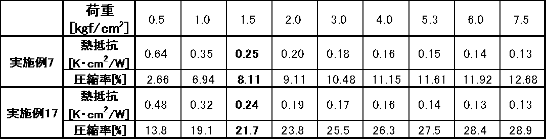
- the obtained heat conductive sheet was evaluated in the same manner as in Example 1. The results are shown in Table 3. Moreover, the compression rate in each load was measured. The measurement results are shown in Table 5-2.
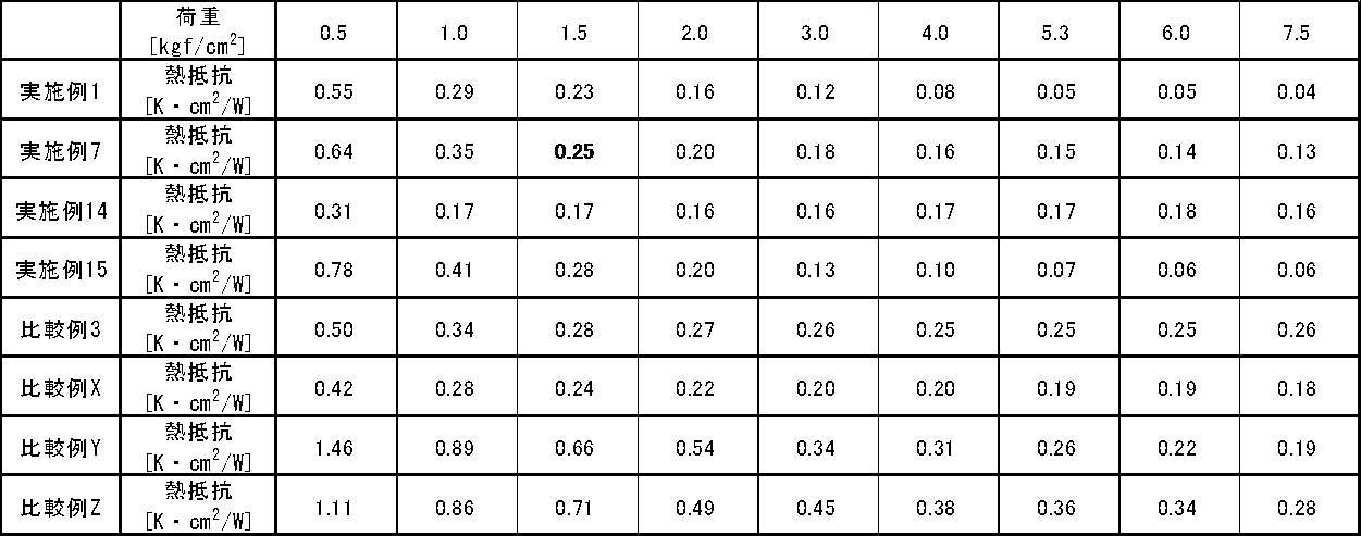
- Comparative Examples X, Y, Z The relationship between the load and the thermal resistance of the commercially available thermal conductive sheet was measured in the same manner as in Example 1. The results are shown in Table 4 and FIG.
- the heat conductive sheet of Comparative Example X is SS-HCT ⁇ 50-302 (thickness 0.2 mm) manufactured by Affine Industries Co., Ltd.
- the heat conductive sheet of Comparative Example Y is an indium sheet manufactured by Axis
- the heat conductive sheet of Comparative Example Z is an indium sheet manufactured by Nilaco.
- the heat conductive sheets of Examples 1 to 15 have an average thickness as thin as 500 ⁇ m or less, the thermal resistance under a load of 7.5 kgf / cm 2 measured according to ASTM-D5470 is 0.17 K ⁇ cm. It was less than 2 / W, had excellent thermal resistance, and was excellent in flexibility.
- thermal conductive sheet of the present invention has high thermal conductivity, for example, CPU, MPU, power transistor, LED, laser diode, various batteries (lithium ion battery, etc.) that adversely affect the efficiency and life of element operation depending on temperature.
- various secondary devices various fuel cells, capacitors, amorphous silicon, crystalline silicon, compound semiconductors, various solar cells such as wet solar cells), and other heating devices that require effective use of heat It is preferably used around a heat source, around a heat exchanger and a heat pipe of a floor heating device, and the like.
Landscapes
- Engineering & Computer Science (AREA)
- Mechanical Engineering (AREA)
- Chemical & Material Sciences (AREA)
- Physics & Mathematics (AREA)
- Thermal Sciences (AREA)
- Materials Engineering (AREA)
- Chemical Kinetics & Catalysis (AREA)
- Combustion & Propulsion (AREA)
- Organic Chemistry (AREA)
- Cooling Or The Like Of Semiconductors Or Solid State Devices (AREA)
- Compositions Of Macromolecular Compounds (AREA)
- Cooling Or The Like Of Electrical Apparatus (AREA)
Abstract
Description
例えば、マトリックス内に配合されている無機物フィラーの充填率を高めることが行われている。しかし、無機物フィラーの充填率を高めると柔軟性が損なわれたり、無機物フィラーの充填率が高いことから粉落ちが発生するおそれがあるため、無機物フィラーの充填率を高める方法には限界がある。
また、窒化ホウ素(BN)、黒鉛等の鱗片状粒子、炭素繊維などをマトリックス内に充填させる技術が提案されている(例えば、特許文献1及び2参照)。これらの提案の技術は、鱗片状粒子などが有する熱伝導率の異方性を利用する技術である。例えば、炭素繊維の場合、繊維方向には約600W/m・K~1,200W/m・Kの熱伝導率を有している。窒化ホウ素の場合には、面方向では約110W/m・K、面方向に対して垂直な方向では約2W/m・K程度であり、異方性を有することが知られている。
前記炭素繊維を用いると、優れた高熱伝導性と柔軟性とを両立した熱伝導性シートが得られる(例えば、特許文献3参照)。しかし、厚みが薄いシート(例えば、平均厚みが500μm以下)では、界面の熱抵抗が大きくなるため、近年求められる優れた高熱伝導性と、優れた柔軟性とを両立できる熱伝導性シートが得られていない。
<1> 半導体装置の熱源と放熱部材との間に挟持される熱伝導性シートであって、
バインダーと、炭素繊維と、無機物フィラーとを含有し、
前記炭素繊維の平均繊維長が、50μm~250μmであり、
ASTM-D5470に従って測定される、荷重7.5kgf/cm2条件下での熱抵抗が、0.17K・cm2/W未満であり、
前記熱伝導性シートの平均厚みが、500μm以下であることを特徴とする熱伝導性シートである。
<2> ASTM-D5470に従って熱抵抗を測定する際の荷重2.0kgf/cm2~荷重7.5kgf/cm2の範囲において、熱抵抗が、0.20K・cm2/W以下である前記<1>に記載の熱伝導性シートである。
<3> 炭素繊維の一部が、熱伝導性シートの表面に、前記炭素繊維の長軸が前記熱伝導性シートの面方向に沿って、配されている前記<1>から<2>のいずれかに記載の熱伝導性シートである。
<4> 無機物フィラーが、アルミナを含有する前記<1>から<3>のいずれかに記載の熱伝導性シートである。
<5> アルミナの平均粒径が、1μm~5μmである前記<4>に記載の熱伝導性シートである。
<6> 無機物フィラーが、窒化アルミニウムを含有する前記<1>から<5>のいずれかに記載の熱伝導性シートである。
<7> 炭素繊維の含有量が、20体積%~40体積%である前記<1>から<6>のいずれかに記載の熱伝導性シートである。
<8> 無機物フィラーの含有量が、30体積%~55体積%である前記<1>から<7>のいずれかに記載の熱伝導性シートである。
<9> 熱伝導性シートの平均厚み(μm)が、炭素繊維の平均繊維長(μm)よりも大きい前記<1>から<8>のいずれかに記載の熱伝導性シートである。
<10> 前記<1>から<9>のいずれかに記載の熱伝導性シートの製造方法であって、
バインダー前駆体と、炭素繊維と、無機物フィラーとを含有する熱伝導性組成物を押出機で押出して、押出成形物を得る押出成形工程と、
前記押出成形物を硬化させて硬化物とする硬化工程と、
前記硬化物を、前記押出しの方向に対し垂直方向に平均厚み500μm以下に切断する切断工程とを含むことを特徴とする熱伝導性シートの製造方法である。
<11> 熱源と、放熱部材と、前記熱源と前記放熱部材との間に挟持される熱伝導性シートとを有し、
前記熱伝導性シートが、前記<1>から<9>のいずれかに記載の熱伝導性シートであることを特徴とする半導体装置である。
本発明の熱伝導性シートは、バインダーと、炭素繊維と、無機物フィラーとを少なくとも含有し、更に必要に応じて、その他の成分を含有する。
前記熱伝導性シートは、半導体装置の熱源と放熱部材との間に挟持され使用される。
前記バインダーとしては、特に制限はなく、目的に応じて適宜選択することができ、例えば、バインダー樹脂などが挙げられる。前記バインダー樹脂としては、例えば、熱可塑性ポリマー、熱硬化性ポリマーの硬化物などが挙げられる。
前記熱可塑性エラストマーとしては、例えば、スチレン系熱可塑性エラストマー、オレフィン系熱可塑性エラストマー、塩化ビニル系熱可塑性エラストマー、ポリエステル系熱可塑性エラストマー、ポリウレタン系熱可塑性エラストマー、ポリアミド系熱可塑性エラストマーなどが挙げられる。これらは、1種単独で使用してもよいし、2種以上を併用してもよい。
前記炭素繊維としては、平均繊維長(平均長軸長さ)が、50μm~250μmであれば、特に制限はなく、目的に応じて適宜選択することができ、例えば、ピッチ系、PAN系、アーク放電法、レーザー蒸発法、CVD法(化学気相成長法)、CCVD法(触媒化学気相成長法)等で合成されたものを用いることができる。これらの中でも、熱伝導性の点からピッチ系炭素繊維が特に好ましい。
前記炭素繊維は、必要に応じて、その一部又は全部を表面処理して用いることができる。前記表面処理としては、例えば、酸化処理、窒化処理、ニトロ化、スルホン化、あるいはこれらの処理によって表面に導入された官能基若しくは炭素繊維の表面に、金属、金属化合物、有機化合物等を付着あるいは結合させる処理などが挙げられる。前記官能基としては、例えば、水酸基、カルボキシル基、カルボニル基、ニトロ基、アミノ基などが挙げられる。
ここで、前記炭素繊維の平均長軸長さ、及び平均短軸長さは、例えばマイクロスコープ、走査型電子顕微鏡(SEM)などにより測定することができる。
前記無機物フィラーとしては、その形状、材質、平均粒径などについては特に制限はなく、目的に応じて適宜選択することができる。前記形状としては、特に制限はなく、目的に応じて適宜選択することができ、例えば、球状、楕円球状、塊状、粒状、扁平状、針状などが挙げられる。これらの中でも、球状、楕円形状が充填性の点から好ましく、球状が特に好ましい。
なお、本明細書において、前記無機物フィラーは、前記炭素繊維とは異なる。
前記無機物フィラーがアルミナの場合、その平均粒径は、1μm~10μmが好ましく、1μm~5μmがより好ましく、4μm~5μmが特に好ましい。前記平均粒径が、1μm未満であると、粘度が大きくなり、混合しにくくなることがあり、10μmを超えると、前記熱伝導性シートの熱抵抗が大きくなることがある。
前記無機物フィラーが窒化アルミニウムの場合、その平均粒径は、0.3μm~6.0μmが好ましく、0.3μm~2.0μmがより好ましく、0.5μm~1.5μmが特に好ましい。前記平均粒径が、0.3μm未満であると、粘度が大きくなり、混合しにくくなることがあり、6.0μmを超えると、前記熱伝導性シートの熱抵抗が大きくなることがある。
前記無機物フィラーの平均粒径は、例えば、粒度分布計、走査型電子顕微鏡(SEM)により測定することができる。
前記無機物フィラーがアルミナの場合、その比表面積は、0.3m2/g~0.9m2/gが好ましい。
前記無機物フィラーが窒化アルミニウムの場合、その比表面積は、1m2/g~3m2/gが好ましい。
前記無機物フィラーの比表面積は、例えば、BET法により測定できる。
前記その他の成分としては、特に制限はなく、目的に応じて適宜選択することができ、例えば、チキソトロピー性付与剤、分散剤、硬化促進剤、遅延剤、微粘着付与剤、可塑剤、難燃剤、酸化防止剤、安定剤、着色剤などが挙げられる。
前記圧縮率は、以下の式により求めることができる。
圧縮率(%)=100×(X-Y)/X
X:荷重をかける前の熱伝導性シートの平均厚み(μm)
Y:荷重7.5kgf/cm2をかけた後の熱伝導性シートの平均厚み(μm)
ここで、荷重をかけて熱抵抗を測定するのは、使用時には、通常、半導体装置の熱源と放熱部材との間に挟持されることで熱伝導性シートに荷重がかかるためである。そして、熱伝導性シートに荷重がかかっている場合と、荷重がかかっていない場合とでは、前記熱伝導性シートの厚み、前記熱伝導性シート内の前記炭素繊維の密度、及び配向、並びに前記熱伝導性シート内の前記無機物フィラーの密度などが異なるため、熱抵抗が変化する。
本発明の熱伝導性シートの製造方法は、押出成形工程と、硬化工程と、切断工程とを少なくとも含み、更に必要に応じてその他の工程を含んでなる。
前記押出成形工程は、熱伝導性組成物を押出機で押出して、押出成形物を得る工程であれば、特に制限はなく、目的に応じて適宜選択することができる。
前記熱伝導性組成物は、バインダー前駆体と、炭素繊維と、無機物フィラーとを含有し、更に必要に応じて、その他の成分を含有する。
前記炭素繊維は、本発明の前記熱伝導性シートの説明において例示した前記炭素繊維である。
前記無機物フィラーは、本発明の前記熱伝導性シートの説明において例示した前記無機物フィラーである。
前記押出機の押出口には、通常、複数のスリットが設けられており、これにより、炭素繊維が押出し方向に配向される。
前記スリットの形状、大きさとしては、特に制限はなく、目的に応じて適宜選択することができるが、前記スリットの形状としては、例えば、平板状、格子状、ハニカム状などが挙げられる。前記スリットの大きさ(幅)としては、特に制限はなく、目的に応じて適宜選択することができるが、0.5mm~10mmが好ましい。
前記熱伝導性組成物の押出し速度としては、特に制限はなく、目的に応じて適宜選択することができるが、0.001L/min以上が好ましい。
また、図1A及び図1Bに示すように、炭素繊維11、及び無機物フィラー12を含む熱伝導性組成物を押出成形することで、炭素繊維を押出し方向に配向させることができる。
ここで、前記微粘着性とは、経時及び湿熱による接着力上昇が少ない再剥離性を持ち、被着体に貼った場合に簡単に位置がずれない程度の粘着性を有することを意味する。
前記硬化工程は、前記押出成形物を硬化させて硬化物とする工程である。
前記押出成形工程で成形された押出成形物は、用いるバインダー前駆体に応じた適切な硬化反応により硬化物となる。
前記押出成形物の硬化方法としては、特に制限はなく、目的に応じて適宜選択することができるが、前記バインダー前駆体としてシリコーン樹脂等の熱硬化性ポリマーを用いる場合には、加熱により硬化させることが好ましい。
前記加熱に用いる装置としては、例えば、遠赤外炉、熱風炉などが挙げられる。
前記加熱温度としては、特に制限はなく、目的に応じて適宜選択することができるが、40℃~150℃で行うことが好ましい
前記シリコーン樹脂が硬化したシリコーン硬化物の柔軟性は、特に制限はなく、目的に応じて適宜選択することができ、例えば、シリコーン硬化物の架橋密度、炭素繊維の充填量、無機物フィラーの充填量などによって調整することができる。
前記切断工程としては、前記硬化物を、前記押出しの方向に対し垂直方向に平均厚み500μm以下に切断する工程であれば、特に制限はなく、目的に応じて適宜選択することができる。
また、前記付加反応型液状シリコーン樹脂における、前記A液と前記B液との混合比率(質量比)がA液:B液=5:5~6:4の範囲にある場合には、切断時に炭素繊維の一部が、熱伝導性シートの表面に、前記炭素繊維の長軸が前記熱伝導性シートの面方向に沿って、付着することで、前記熱伝導性シートの面方向に沿って配された炭素繊維を熱伝導性シートの表面に有する熱伝導性シートを得ることができる。
図2に示すように、押出し、成形、硬化、切断(スライス)などの一連の工程を経て熱伝導性シートが製造される。
図2に示すように、まず、バインダー前駆体、炭素繊維、及び無機物フィラーを配合及び撹拌して熱伝導性組成物を調製する。次に、調製した熱伝導性組成物を押出成形する際に、複数のスリットを通過させることで熱伝導性組成物中に配合された炭素繊維を熱伝導性シートの厚み方向に配向させる。次に、得られた成形体を硬化させた後、硬化物を前記押出し方向に対し垂直方向に超音波カッターで所定の厚みに切断(スライス)することにより、熱伝導性シートが作製できる。
本発明の半導体装置は、放熱部材と、熱源と、熱伝導性シートとを有し、更に必要に応じて、その他の部材を有する。
前記熱伝導性シートは、前記熱源と前記放熱部材との間に挟持されている。
前記熱源としての半導体素子としては、特に制限はなく、目的に応じて適宜選択することができ、例えば、CPU、MPU、グラフィック演算素子などが挙げられる。
前記放熱部材としては、半導体素子から発生する熱を伝導して外部に放散させるものであれば、特に制限はなく、目的に応じて適宜選択することができ、例えば、放熱器、冷却器、ヒートシンク、ヒートスプレッダー、ダイパッド、プリント基板、冷却ファン、ペルチェ素子、ヒートパイプ、筐体などが挙げられる。
前記熱伝導性シートは、本発明の前記熱伝導性シートである。
-熱伝導性シートの作製-
シリコーンA液(ビニル基を有するオルガノポリシロキサン)と、シリコーンB液(H-Si基を有するオルガノポリシロキサン)とを3:7(A液:B液)の質量比で混合した二液性の付加反応型液状シリコーン樹脂に、分級して比表面積を調整したアルミナ(平均粒径4μm、球状、比表面積0.3m2/g、新日鉄住金マテリアルズ株式会社マイクロン社製)18体積%と、窒化アルミニウム(平均粒径1μm、球状、比表面積3m2/g、Hグレード、株式会社トクヤマ製)21体積%と、ピッチ系炭素繊維(平均繊維長100μm、平均短軸長さ9.2μm、XN100-10M、日本グラファイトファイバー株式会社製)31体積%とを分散させて、シリコーン樹脂組成物を調製した。なお、上記配合における体積%は、得られる熱伝導性シートにおける体積%である。
また、アルミナ及び窒化アルミニウムは、シランカップリング剤でカップリング処理したものを用いた。
得られたシリコーン樹脂組成物を押出機で型(中空円柱状)の中に押出成形し、シリコーン成形体を作製した。押出機の押出口にはスリット(吐出口形状:平板)が形成されている。
得られたシリコーン成形体をオーブンにて100℃で6時間加熱して、シリコーン硬化物とした。
得られたシリコーン硬化物を、平均厚みが100μmとなるように超音波カッターで押出しの方向に対し垂直方向にスライス切断した(発信周波数20.5kHz、振幅50μm~70μm)。以上により、平均厚み100μm、縦30mm、横30mmの正方形状の実施例1の熱伝導性シートを作製した。
得られた熱伝導性シートは、その断面をマイクロスコープ(HiROX Co Ltd製、KH7700)で観察したところ、ピッチ系炭素繊維が熱伝導性シートの厚み方向に対し0度~5度に配向していた。図4に、熱伝導性シートの表面のSEM写真を示した。
また、得られた熱伝導性シートの圧縮率を測定した。その結果を表5-1に示した。
<熱抵抗>
ASTM-D5470に従って熱抵抗を測定した。結果を表1、表4、及び図5に示した。
熱抵抗は、荷重0.5kgf/cm2、1.0kgf/cm2、1.5kgf/cm2、2.0kgf/cm2、3.0kgf/cm2、4.0kgf/cm2、5.3kgf/cm2、6.0kgf/cm2、7.5kgf/cm2の条件下でそれぞれ測定した。
柔軟性は熱伝導性シートの圧縮率で評価した。具体的には、熱伝導性シートに荷重7.5kgf/cm2をかけた時の圧縮率を測定し、以下の評価基準で評価した。
〔評価基準〕
○:圧縮率が5%以上
×:圧縮率が5%未満
炭素繊維の一部が、熱伝導性シートの表面に、前記炭素繊維の長軸が前記熱伝導性シートの面方向に沿って、配されているか否かを図4のようなSEM写真により確認した。以下の評価基準で評価した。結果を表1に示した。
〔評価基準〕
A:配されている
B:配されていない
実施例1において、炭素繊維の種類及び量(体積%)、アルミナの種類及び量(体積%)、窒化アルミニウムの種類及び量(体積%)、並びに熱伝導性シートの平均厚みを、表1~3に記載の炭素繊維の種類及び量(体積%)、アルミナの種類及び量(体積%)、窒化アルミニウムの種類及び量(体積%)、並びに熱伝導性シートの平均厚みに変更した以外は、実施例1と同様にして、熱伝導性シートを作製した。
得られた熱伝導性シートについて、実施例1と同様にして評価を行った。結果を表1~4及び図5に示した。
実施例1において、シリコーンA液とシリコーンB液との配合比率(質量比)を5:5に変更した以外は、実施例1と同様にして、熱伝導性シートを作製した。
得られた熱伝導性シートについて、実施例1と同様にして評価を行った。結果を表3及び図5に示した。また、各荷重における圧縮率を測定した。測定結果を表5-1に示した。更に、熱伝導性シートのSEM写真を図6に示した。ここで、SEM写真上の矢印よりも上の部分は熱伝導性シートの表面を示し、下の部分は熱伝導性シートの断面を示す。
実施例7において、シリコーンA液とシリコーンB液との配合比率(質量比)を5:5に変更した以外は、実施例7と同様にして、熱伝導性シートを作製した。
得られた熱伝導性シートについて、実施例1と同様にして評価を行った。結果を表3に示した。また、各荷重における圧縮率を測定した。測定結果を表5-2に示した。
市販品の熱伝導性シートについて、荷重と熱抵抗との関係を実施例1と同様にして測定した。結果を表4及び図5に示した。
なお、比較例Xの熱伝導性シートは、親和産業株式会社製SS-HCTα50-302(厚み0.2mm)であり、比較例Yの熱伝導性シートは、アクシス社製のインジウムシートであり、比較例Zの熱伝導性シートは、Nilaco社製のインジウムシートである。


*炭素繊維(平均繊維長:100μm):XN100-10M(日本グラファイトファイバー株式会社製)
*炭素繊維(平均繊維長:150μm):XN100-15M(日本グラファイトファイバー株式会社製)
*炭素繊維(平均繊維長:250μm):XN100-25M(日本グラファイトファイバー株式会社製)
*アルミナ:新日鉄住金マテリアルズ株式会社製
*AlN(比表面積:1m2/g):JC(東洋アルミ株式会社製)
*AlN(比表面積:3m2/g):Hグレード(トクヤマ株式会社製)
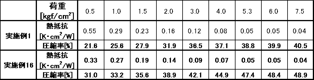
実施例1において、シリコーンA液とシリコーンB液との配合比率(質量比)をA液:B液=5:5に変えた実施例16の熱伝導性シートは、炭素繊維の一部が、熱伝導性シートの表面に、前記炭素繊維の長軸が前記熱伝導性シートの面方向に沿って、配されることで、発熱体もしくは放熱部材と炭素繊維の接触面積が増加して、熱抵抗の低下をもたらした。また、シリコーンA液とシリコーンB液の配合比率(質量比)をA液:B液=5:5とすることで柔軟性が向上し、炭素繊維の一部が熱伝導性シート表面方向に沿って付着し、低荷重の場合における熱抵抗の低下につながった。
実施例7において、シリコーンA液とシリコーンB液との配合比率(質量比)をA液:B液=5:5に変えた実施例17の熱伝導性シートも上記と同様の傾向が得られた。
一方、比較例1~3では、優れた熱抵抗と、優れた柔軟性とを両立できていなかった。比較例4では、シート形成性が悪く、評価ができなかった。
2 半導体素子
3 熱伝導性シート
4 放熱部材
10 半導体装置
11 炭素繊維
12 無機物フィラー
Claims (11)
- 半導体装置の熱源と放熱部材との間に挟持される熱伝導性シートであって、
バインダーと、炭素繊維と、無機物フィラーとを含有し、
前記炭素繊維の平均繊維長が、50μm~250μmであり、
ASTM-D5470に従って測定される、荷重7.5kgf/cm2条件下での熱抵抗が、0.17K・cm2/W未満であり、
前記熱伝導性シートの平均厚みが、500μm以下であることを特徴とする熱伝導性シート。 - ASTM-D5470に従って熱抵抗を測定する際の荷重2.0kgf/cm2~荷重7.5kgf/cm2の範囲において、熱抵抗が、0.20K・cm2/W以下である請求項1に記載の熱伝導性シート。
- 炭素繊維の一部が、熱伝導性シートの表面に、前記炭素繊維の長軸が前記熱伝導性シートの面方向に沿って、配されている請求項1から2のいずれかに記載の熱伝導性シート。
- 無機物フィラーが、アルミナを含有する請求項1から3のいずれかに記載の熱伝導性シート。
- アルミナの平均粒径が、1μm~5μmである請求項4に記載の熱伝導性シート。
- 無機物フィラーが、窒化アルミニウムを含有する請求項1から5のいずれかに記載の熱伝導性シート。
- 炭素繊維の含有量が、20体積%~40体積%である請求項1から6のいずれかに記載の熱伝導性シート。
- 無機物フィラーの含有量が、30体積%~55体積%である請求項1から7のいずれかに記載の熱伝導性シート。
- 熱伝導性シートの平均厚み(μm)が、炭素繊維の平均繊維長(μm)よりも大きい請求項1から8のいずれかに記載の熱伝導性シート。
- 請求項1から9のいずれかに記載の熱伝導性シートの製造方法であって、
バインダー前駆体と、炭素繊維と、無機物フィラーとを含有する熱伝導性組成物を押出機で押出して、押出成形物を得る押出成形工程と、
前記押出成形物を硬化させて硬化物とする硬化工程と、
前記硬化物を、前記押出しの方向に対し垂直方向に平均厚み500μm以下に切断する切断工程とを含むことを特徴とする熱伝導性シートの製造方法。 - 熱源と、放熱部材と、前記熱源と前記放熱部材との間に挟持される熱伝導性シートとを有し、
前記熱伝導性シートが、請求項1から9のいずれかに記載の熱伝導性シートであることを特徴とする半導体装置。
Priority Applications (3)
| Application Number | Priority Date | Filing Date | Title |
|---|---|---|---|
| US14/892,724 US9966324B2 (en) | 2013-06-27 | 2014-06-18 | Thermally conductive sheet, method for producing same, and semiconductor device |
| KR1020167001799A KR101616239B1 (ko) | 2013-06-27 | 2014-06-18 | 열전도성 시트 및 그의 제조 방법, 및 반도체 장치 |
| CN201480033308.4A CN105283952A (zh) | 2013-06-27 | 2014-06-18 | 导热性片材及其制备方法、以及半导体装置 |
Applications Claiming Priority (4)
| Application Number | Priority Date | Filing Date | Title |
|---|---|---|---|
| JP2013135221 | 2013-06-27 | ||
| JP2013-135221 | 2013-06-27 | ||
| JP2014116981A JP5779693B2 (ja) | 2013-06-27 | 2014-06-05 | 熱伝導性シート、及びその製造方法、並びに半導体装置 |
| JP2014-116981 | 2014-06-05 |
Publications (1)
| Publication Number | Publication Date |
|---|---|
| WO2014208408A1 true WO2014208408A1 (ja) | 2014-12-31 |
Family
ID=52141748
Family Applications (1)
| Application Number | Title | Priority Date | Filing Date |
|---|---|---|---|
| PCT/JP2014/066095 Ceased WO2014208408A1 (ja) | 2013-06-27 | 2014-06-18 | 熱伝導性シート、及びその製造方法、並びに半導体装置 |
Country Status (6)
| Country | Link |
|---|---|
| US (1) | US9966324B2 (ja) |
| JP (1) | JP5779693B2 (ja) |
| KR (1) | KR101616239B1 (ja) |
| CN (2) | CN107871721B (ja) |
| TW (1) | TWI609077B (ja) |
| WO (1) | WO2014208408A1 (ja) |
Cited By (1)
| Publication number | Priority date | Publication date | Assignee | Title |
|---|---|---|---|---|
| JP2022068136A (ja) * | 2020-10-21 | 2022-05-09 | デクセリアルズ株式会社 | 熱伝導性シート及び熱伝導性シートの製造方法 |
Families Citing this family (33)
| Publication number | Priority date | Publication date | Assignee | Title |
|---|---|---|---|---|
| DE102015118245B4 (de) * | 2015-10-26 | 2024-10-10 | Infineon Technologies Austria Ag | Elektronische Komponente mit einem thermischen Schnittstellenmaterial, Herstellungsverfahren für eine elektronische Komponente, Wärmeabfuhrkörper mit einem thermischen Schnittstellenmaterial und thermisches Schnittstellenmaterial |
| JP6301978B2 (ja) | 2016-01-26 | 2018-03-28 | デクセリアルズ株式会社 | 熱伝導シート、熱伝導シートの製造方法、放熱部材及び半導体装置 |
| JP6947158B2 (ja) * | 2016-02-25 | 2021-10-13 | 日本ゼオン株式会社 | 熱伝導シートおよびその製造方法、ならびに放熱装置 |
| JP2017199776A (ja) | 2016-04-27 | 2017-11-02 | 北川工業株式会社 | 熱伝導シート、および、熱伝導シートの製造方法 |
| JP6753745B2 (ja) * | 2016-09-12 | 2020-09-09 | デクセリアルズ株式会社 | 熱伝導シート、及び半導体装置 |
| US20190300771A1 (en) | 2016-09-28 | 2019-10-03 | Teijin Limited | Heat dissipation sheet |
| EP3608384B1 (en) * | 2017-06-27 | 2022-02-09 | Sekisui Polymatech Co., Ltd. | Heat-conductive sheet |
| JP6393816B2 (ja) * | 2017-10-13 | 2018-09-19 | デクセリアルズ株式会社 | 熱伝導シート、熱伝導シートの製造方法、放熱部材及び半導体装置 |
| JP6965717B2 (ja) * | 2017-12-13 | 2021-11-10 | トヨタ自動車株式会社 | 電池パックの製造方法 |
| US11610829B2 (en) * | 2018-02-14 | 2023-03-21 | Sekisui Polymatech Co., Ltd. | Heat-conductive sheet |
| WO2019244889A1 (ja) * | 2018-06-22 | 2019-12-26 | 積水ポリマテック株式会社 | 熱伝導性シート |
| CN112352476A (zh) * | 2018-07-12 | 2021-02-09 | 迪睿合株式会社 | 拾取装置、安装装置、拾取方法、安装方法 |
| JP6807355B2 (ja) * | 2018-07-18 | 2021-01-06 | デクセリアルズ株式会社 | 熱伝導性シート及びその製造方法、熱伝導性シートの実装方法 |
| JP7233564B2 (ja) * | 2019-11-07 | 2023-03-06 | 帝人株式会社 | 放熱シート及びその製造方法 |
| CN111253828A (zh) * | 2019-11-26 | 2020-06-09 | 东莞市美庆电子科技有限公司 | 一种导热垫片及其制备方法 |
| JP7542317B2 (ja) * | 2020-02-06 | 2024-08-30 | 積水化学工業株式会社 | 熱伝導性樹脂シート |
| KR102282967B1 (ko) | 2020-03-24 | 2021-07-28 | 실리콘밸리(주) | 종방향 배열형 열확산시트 및 그 제조방법 |
| EP3961696A4 (en) * | 2020-05-28 | 2023-07-05 | Dexerials Corporation | THERMAL CONDUCTING COATING, PROCESS FOR ITS MANUFACTURE, HEAT-DISSIPTING STRUCTURE AND ELECTRONIC DEVICE |
| KR20230019413A (ko) | 2020-05-29 | 2023-02-08 | 세키수이 폴리머텍 가부시키가이샤 | 열전도성 시트 및 그 제조 방법 |
| US11939494B2 (en) | 2020-08-19 | 2024-03-26 | Lg Chem, Ltd. | Resin composition for bonding semiconductor and adhesive film for semiconductor using the same |
| JP7613652B2 (ja) * | 2020-09-02 | 2025-01-15 | デクセリアルズ株式会社 | 熱伝導部材及びその製造方法、並びに放熱構造体 |
| CN112938649B (zh) * | 2021-01-29 | 2022-09-13 | 深圳市鸿富诚新材料股份有限公司 | 一种化学处理式碳纤维排序工艺及碳纤维切断装置 |
| JP2022127596A (ja) * | 2021-02-19 | 2022-08-31 | デクセリアルズ株式会社 | 熱伝導性シート及び熱伝導性シートの製造方法 |
| WO2022176748A1 (ja) * | 2021-02-19 | 2022-08-25 | デクセリアルズ株式会社 | 熱伝導性シート及び熱伝導性シートの製造方法 |
| KR102480164B1 (ko) | 2021-02-26 | 2022-12-23 | 주식회사 케이비엘러먼트 | 그래핀 소재를 포함하는 열전도성 시트의 제조 방법 및 이의 제조 방법으로 제조된 열전도성 시트 |
| CN113560146A (zh) * | 2021-07-09 | 2021-10-29 | 常州富烯科技股份有限公司 | 纵向高导热垫片、制备方法及应用 |
| CN113829406B (zh) * | 2021-11-09 | 2024-03-01 | 常州富烯科技股份有限公司 | 导热片制备方法 |
| CN114228205A (zh) * | 2021-12-06 | 2022-03-25 | 深圳联腾达科技有限公司 | 一种实验室简易制备定向排序碳纤维导热复合材料的工艺 |
| WO2023182268A1 (ja) | 2022-03-25 | 2023-09-28 | バンドー化学株式会社 | 熱伝導性シート |
| KR102622560B1 (ko) | 2022-05-25 | 2024-01-09 | 실리콘밸리(주) | 수평 및 수직방향으로 배열된 방열패드 및 그 제조방법 |
| KR102607186B1 (ko) | 2022-08-22 | 2023-11-29 | 실리콘밸리(주) | 안테나 내장형 방열패드 및 그 제조방법 |
| KR102743483B1 (ko) | 2022-08-22 | 2024-12-16 | 실리콘밸리(주) | 다중 배열 구조의 방열패드 및 그 제조방법 |
| KR20250087140A (ko) | 2023-12-07 | 2025-06-16 | (주)씨엠테크 | 탄소섬유의 배향성이 향상된 열전도성 시트의 제조방법 |
Citations (2)
| Publication number | Priority date | Publication date | Assignee | Title |
|---|---|---|---|---|
| JPH11302545A (ja) * | 1998-02-18 | 1999-11-02 | Nippon Mitsubishi Oil Corp | シリコーンゴム複合物 |
| JP2012023335A (ja) * | 2010-06-17 | 2012-02-02 | Sony Chemical & Information Device Corp | 熱伝導性シート及びその製造方法 |
Family Cites Families (11)
| Publication number | Priority date | Publication date | Assignee | Title |
|---|---|---|---|---|
| EP0937744A1 (en) | 1998-02-18 | 1999-08-25 | Nippon Oil Co. Ltd. | Silicone rubber composite |
| JP4657816B2 (ja) | 2005-06-03 | 2011-03-23 | ポリマテック株式会社 | 熱伝導性成形体の製造方法及び熱伝導性成形体 |
| JP4814550B2 (ja) * | 2005-06-03 | 2011-11-16 | ポリマテック株式会社 | 熱伝導性成形体の製造方法 |
| CN1979826A (zh) * | 2005-12-01 | 2007-06-13 | 财团法人工业技术研究院 | 散热装置及其所使用的高导热复合材料 |
| DE112008002566B4 (de) * | 2007-09-26 | 2014-08-28 | Mitsubishi Electric Corp. | Wärmeleitfähige Lage und Verfahren zum Herstellen derselben, und Leistungsmodul |
| WO2011158942A1 (ja) * | 2010-06-17 | 2011-12-22 | ソニーケミカル&インフォメーションデバイス株式会社 | 熱伝導性シート及びその製造方法 |
| JP5671266B2 (ja) * | 2010-06-17 | 2015-02-18 | デクセリアルズ株式会社 | 熱伝導性シート |
| JP2012015273A (ja) | 2010-06-30 | 2012-01-19 | Hitachi Chem Co Ltd | 熱伝導シート、熱伝導シートの製造方法、及び熱伝導シートを用いた放熱装置 |
| JP5696599B2 (ja) * | 2011-06-24 | 2015-04-08 | 日本ゼオン株式会社 | 熱伝導性感圧接着剤組成物、熱伝導性感圧接着性シート状成形体、これらの製造方法、及び電子機器 |
| JP5416174B2 (ja) | 2011-07-08 | 2014-02-12 | ポリマテック株式会社 | 熱伝導性成形体 |
| CN102649896B (zh) * | 2012-05-29 | 2015-11-04 | 安顿雷纳(上海)纤维材料科技有限公司 | 一种新型高导热散热涂料及其制造方法 |
-
2014
- 2014-06-05 JP JP2014116981A patent/JP5779693B2/ja active Active
- 2014-06-18 WO PCT/JP2014/066095 patent/WO2014208408A1/ja not_active Ceased
- 2014-06-18 CN CN201711157890.7A patent/CN107871721B/zh active Active
- 2014-06-18 US US14/892,724 patent/US9966324B2/en active Active
- 2014-06-18 CN CN201480033308.4A patent/CN105283952A/zh active Pending
- 2014-06-18 KR KR1020167001799A patent/KR101616239B1/ko active Active
- 2014-06-24 TW TW103121773A patent/TWI609077B/zh active
Patent Citations (2)
| Publication number | Priority date | Publication date | Assignee | Title |
|---|---|---|---|---|
| JPH11302545A (ja) * | 1998-02-18 | 1999-11-02 | Nippon Mitsubishi Oil Corp | シリコーンゴム複合物 |
| JP2012023335A (ja) * | 2010-06-17 | 2012-02-02 | Sony Chemical & Information Device Corp | 熱伝導性シート及びその製造方法 |
Cited By (4)
| Publication number | Priority date | Publication date | Assignee | Title |
|---|---|---|---|---|
| JP2022068136A (ja) * | 2020-10-21 | 2022-05-09 | デクセリアルズ株式会社 | 熱伝導性シート及び熱伝導性シートの製造方法 |
| JP7681496B2 (ja) | 2020-10-21 | 2025-05-22 | デクセリアルズ株式会社 | 熱伝導性シート及び熱伝導性シートの製造方法 |
| JP2025085723A (ja) * | 2020-10-21 | 2025-06-05 | デクセリアルズ株式会社 | 熱伝導性シート及び熱伝導性シートの製造方法 |
| JP7814582B2 (ja) | 2020-10-21 | 2026-02-16 | 積水化学工業株式会社 | 熱伝導性シート及び熱伝導性シートの製造方法 |
Also Published As
| Publication number | Publication date |
|---|---|
| TW201500538A (zh) | 2015-01-01 |
| US9966324B2 (en) | 2018-05-08 |
| JP2015029071A (ja) | 2015-02-12 |
| US20160104657A1 (en) | 2016-04-14 |
| JP5779693B2 (ja) | 2015-09-16 |
| KR20160013270A (ko) | 2016-02-03 |
| KR101616239B1 (ko) | 2016-04-27 |
| TWI609077B (zh) | 2017-12-21 |
| CN107871721B (zh) | 2020-09-22 |
| CN107871721A (zh) | 2018-04-03 |
| CN105283952A (zh) | 2016-01-27 |
Similar Documents
| Publication | Publication Date | Title |
|---|---|---|
| JP5779693B2 (ja) | 熱伝導性シート、及びその製造方法、並びに半導体装置 | |
| JP6082777B2 (ja) | 熱伝導性シート及びその製造方法 | |
| KR101715988B1 (ko) | 열전도성 시트 및 그 제조 방법 | |
| JP5882581B2 (ja) | 熱伝導シート、その製造方法及びこれを用いた放熱装置 | |
| JP6178389B2 (ja) | 熱伝導シートの製造方法、熱伝導シート、及び半導体装置 | |
| CN102037798A (zh) | 散热片及散热装置 | |
| JP2015035580A (ja) | 熱伝導性シート | |
| JP2010132866A (ja) | 熱伝導シート、この熱伝導シートの製造方法及び熱伝導シートを用いた放熱装置 | |
| JP6739478B2 (ja) | 熱伝導性シートの製造方法 | |
| TWI714804B (zh) | 熱傳導片及半導體裝置 | |
| KR20210018427A (ko) | 열전도성 시트 및 그의 제조 방법, 열전도성 시트의 실장 방법 | |
| WO2020153346A1 (ja) | 熱伝導性シートの製造方法 | |
| WO2020162164A1 (ja) | 熱伝導シート、熱伝導シートの実装方法、電子機器の製造方法 | |
| TW202132532A (zh) | 熱傳導性片材及其製造方法、熱傳導性片材之安裝方法 | |
| JP2011249681A (ja) | 熱伝導性シート及び半導体装置 | |
| US20240120254A1 (en) | Thermally-conductive sheet and electronic device | |
| JP2011249682A (ja) | 熱伝導性シート及び半導体装置 | |
| JP6307288B2 (ja) | 熱伝導性部材、及び半導体装置 | |
| WO2022176823A1 (ja) | 熱伝導シート | |
| WO2020153348A1 (ja) | 熱伝導性シート、熱伝導性シートの製造方法 | |
| WO2021241249A1 (ja) | 熱伝導シート及びその製造方法、並びに放熱構造体及び電子機器 | |
| HK1179999B (en) | Thermally conductive sheet and process for producing same |
Legal Events
| Date | Code | Title | Description |
|---|---|---|---|
| WWE | Wipo information: entry into national phase |
Ref document number: 201480033308.4 Country of ref document: CN |
|
| 121 | Ep: the epo has been informed by wipo that ep was designated in this application |
Ref document number: 14817338 Country of ref document: EP Kind code of ref document: A1 |
|
| DPE2 | Request for preliminary examination filed before expiration of 19th month from priority date (pct application filed from 20040101) | ||
| WWE | Wipo information: entry into national phase |
Ref document number: 14892724 Country of ref document: US |
|
| NENP | Non-entry into the national phase |
Ref country code: DE |
|
| ENP | Entry into the national phase |
Ref document number: 20167001799 Country of ref document: KR Kind code of ref document: A |
|
| 122 | Ep: pct application non-entry in european phase |
Ref document number: 14817338 Country of ref document: EP Kind code of ref document: A1 |