WO2014208363A1 - 吸収性物品とその製造方法 - Google Patents
吸収性物品とその製造方法 Download PDFInfo
- Publication number
- WO2014208363A1 WO2014208363A1 PCT/JP2014/065714 JP2014065714W WO2014208363A1 WO 2014208363 A1 WO2014208363 A1 WO 2014208363A1 JP 2014065714 W JP2014065714 W JP 2014065714W WO 2014208363 A1 WO2014208363 A1 WO 2014208363A1
- Authority
- WO
- WIPO (PCT)
- Prior art keywords
- absorbent
- absorbent article
- continuous
- longitudinal direction
- cuff
- Prior art date
- Legal status (The legal status is an assumption and is not a legal conclusion. Google has not performed a legal analysis and makes no representation as to the accuracy of the status listed.)
- Ceased
Links
Images



Classifications
-
- A—HUMAN NECESSITIES
- A61—MEDICAL OR VETERINARY SCIENCE; HYGIENE
- A61F—FILTERS IMPLANTABLE INTO BLOOD VESSELS; PROSTHESES; DEVICES PROVIDING PATENCY TO, OR PREVENTING COLLAPSING OF, TUBULAR STRUCTURES OF THE BODY, e.g. STENTS; ORTHOPAEDIC, NURSING OR CONTRACEPTIVE DEVICES; FOMENTATION; TREATMENT OR PROTECTION OF EYES OR EARS; BANDAGES, DRESSINGS OR ABSORBENT PADS; FIRST-AID KITS
- A61F13/00—Bandages or dressings; Absorbent pads
- A61F13/15—Absorbent pads, e.g. sanitary towels, swabs or tampons for external or internal application to the body; Supporting or fastening means therefor; Tampon applicators
- A61F13/45—Absorbent pads, e.g. sanitary towels, swabs or tampons for external or internal application to the body; Supporting or fastening means therefor; Tampon applicators characterised by the shape
- A61F13/47—Sanitary towels, incontinence pads or napkins
- A61F13/472—Sanitary towels, incontinence pads or napkins specially adapted for female use
-
- A—HUMAN NECESSITIES
- A61—MEDICAL OR VETERINARY SCIENCE; HYGIENE
- A61F—FILTERS IMPLANTABLE INTO BLOOD VESSELS; PROSTHESES; DEVICES PROVIDING PATENCY TO, OR PREVENTING COLLAPSING OF, TUBULAR STRUCTURES OF THE BODY, e.g. STENTS; ORTHOPAEDIC, NURSING OR CONTRACEPTIVE DEVICES; FOMENTATION; TREATMENT OR PROTECTION OF EYES OR EARS; BANDAGES, DRESSINGS OR ABSORBENT PADS; FIRST-AID KITS
- A61F13/00—Bandages or dressings; Absorbent pads
- A61F13/15—Absorbent pads, e.g. sanitary towels, swabs or tampons for external or internal application to the body; Supporting or fastening means therefor; Tampon applicators
- A61F13/15577—Apparatus or processes for manufacturing
- A61F13/15804—Plant, e.g. involving several steps
-
- A—HUMAN NECESSITIES
- A61—MEDICAL OR VETERINARY SCIENCE; HYGIENE
- A61F—FILTERS IMPLANTABLE INTO BLOOD VESSELS; PROSTHESES; DEVICES PROVIDING PATENCY TO, OR PREVENTING COLLAPSING OF, TUBULAR STRUCTURES OF THE BODY, e.g. STENTS; ORTHOPAEDIC, NURSING OR CONTRACEPTIVE DEVICES; FOMENTATION; TREATMENT OR PROTECTION OF EYES OR EARS; BANDAGES, DRESSINGS OR ABSORBENT PADS; FIRST-AID KITS
- A61F13/00—Bandages or dressings; Absorbent pads
- A61F13/15—Absorbent pads, e.g. sanitary towels, swabs or tampons for external or internal application to the body; Supporting or fastening means therefor; Tampon applicators
- A61F13/45—Absorbent pads, e.g. sanitary towels, swabs or tampons for external or internal application to the body; Supporting or fastening means therefor; Tampon applicators characterised by the shape
- A61F13/47—Sanitary towels, incontinence pads or napkins
- A61F13/472—Sanitary towels, incontinence pads or napkins specially adapted for female use
- A61F13/47236—Sanitary towels, incontinence pads or napkins specially adapted for female use characterised by an unusual contour
- A61F13/47245—Sanitary towels, incontinence pads or napkins specially adapted for female use characterised by an unusual contour with asymmetry around the x or y axis
Definitions
- the present invention relates to an absorbent article such as a sanitary napkin or an incontinence urine pad and a method for producing the same.
- an absorbent article such as a sanitary napkin forms a continuous laminate by sandwiching an absorbent body between a liquid-permeable top sheet and a liquid-impermeable back sheet, and the continuous laminate is formed into a substantially rectangular outer shape. It is obtained by cutting out along the shape (for example, refer to Patent Document 1). Further, in this type of absorbent article, wings for attaching the absorbent article to the crotch part of the underwear are formed on both side portions that are long sides as required (see, for example, Patent Document 2). .
- the absorbent article When the absorbent article is formed with a wide width, the amount of absorption can be increased and the wearer's hip side can be covered over a wide range. However, if the width of the front and rear intermediate portions is excessive, a feeling of strangeness may occur at the time of wearing, and the fit may be reduced.
- An object of the present invention is to provide an absorbent article and a method for manufacturing the same, which are excellent in fit, can improve absorption performance, and can be efficiently produced with less waste of materials.
- the absorbent article of the present invention is an absorbent article in which an absorber (4) is disposed between a liquid-permeable top sheet (2) and a liquid-impermeable back sheet (3),
- the width (W5) of one end (5) in the longitudinal direction (L) of the absorbent article is larger than the width (W6) of the other end (6).
- the width of one end portion is larger than the width of the other end portion.
- the part side can be covered over a wide range. Furthermore, the width of the front and rear intermediate portions does not become excessive according to the narrow front portion. Therefore, the absorbent article can maintain good fit.
- the absorbent body may be rectangular in plan view, but preferably, the width of one end may be larger than the width of the other end in accordance with the outer shape of the absorbent article. In this case, high absorption performance of the absorbent article can be exhibited such that body fluid can be quickly absorbed and the amount of absorption can be increased.
- the absorbent article has a cuff extending in the longitudinal direction at each side portion extending in the longitudinal direction,
- the outer side edge of each cuff extends obliquely along the side,
- the side edge inside each said cuff may be set so that it may extend in parallel with respect to the centerline which bisects the said absorbent article in the width direction which cross
- the width of one end of the cuff in the longitudinal direction is larger than the width of the other end, and the cuff can be securely attached to the absorbent article.
- a production method of the present invention is a method for continuously producing a plurality of the absorbent articles, A top sheet supply step (S1) for supplying a continuous sheet (W2) forming the top sheet (2); An absorbent body supplying step (S2) for intermittently supplying the individual absorbent bodies (4) in the plurality of absorbent articles; A backsheet supply step (S3) for supplying a continuous sheet (W3) forming the backsheet (3); In the state where the plurality of absorbent bodies (4) are sandwiched between the continuous sheets (W2) and (W3), the continuous sheets (W2) and (W3) are joined together to form a continuous laminate (8).
- the continuous laminated body (8) between the absorbent bodies (4) adjacent to each other among the individual absorbent bodies is opposite to the one virtual first cutting line (L1) with respect to the longitudinal direction (L).
- the second absorbent article (1) that follows the preceding absorbent article (1) is cut along a predetermined second virtual second cutting line (L2) that is inclined in the second direction on the side.
- a separation step (S52), The first separation step (S51) and the second separation step (S52) are alternately repeated to obtain individual absorbent articles (1).
- each said cutting line is formed in the direction inclined with respect to the longitudinal direction of the said continuous laminated body, and the 1st (the 1st) at the time of separating (separating) an absorbent article immediately before 2)
- the second (first) cutting line is inclined to the opposite side with the longitudinal direction of the continuous laminate as the center.
- the absorbent article separated from the continuous laminate by the cutting has a shape in which the width of one end in the longitudinal direction is larger than the width of the other end. Since one preceding absorbent article that has been separated is in a posture rotated by 180 degrees with respect to the next adjacent absorbent article, there is no cut loss during the cutting, or the amount of cut loss generated is greatly reduced. . For this reason, it is possible to efficiently produce materials with little waste of materials.
- each absorbent article obtained trapezoidal by making each said cutting line into linear form.
- the cutting line may be a curved shape having an arbitrary shape, for example, a shape that can cover the wearer's buttocks over a wider range.
- the shape of the said cutting line so that the recessed part dented to one absorber side and the convex part protruded to the adjacent absorber side may be formed in each said side part May be set. In this case, it can be set as an absorbent article provided with the wing which protrudes from the both sides of an absorptive article to the side (adjacent absorber side) by this pair of convex parts.
- Another manufacturing method of the present invention is a method for continuously manufacturing a plurality of absorbent articles including a top sheet (2), a back sheet (3), an absorber (4), and a pair of cuffs (15).
- a top sheet supply step (S1) for supplying a continuous sheet (W2) forming the top sheet (2);
- An absorbent body supplying step (S2) for intermittently supplying the individual absorbent bodies (4) in the plurality of absorbent articles;
- a backsheet supply step (S3) for supplying a continuous sheet (W3) forming the backsheet (3); In the state where the plurality of absorbent bodies (4) are sandwiched between the continuous sheets (W2) and (W3), the continuous sheets (W2) and (W3) are joined together to form a continuous laminate (8).
- One of the n cuff members (15C) is cut along a predetermined second virtual second cutting line (L2) inclined in the second direction opposite to the line (L1).
- the cuff members are intermittently arranged on the continuous laminate one after another so that the longitudinal direction of the rectangular cuff member is orthogonal to the transport direction of the continuous laminate.
- the arrangement of the cuff member is easy.
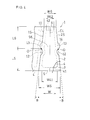
- FIG. 1 is a plan view showing a part of the absorbent article according to the first embodiment of the present invention.
- FIG. 2 is a schematic configuration diagram showing a method for manufacturing an absorbent article of the same example.
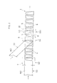
- FIG. 3 is a schematic configuration diagram showing a separation process and the like of the same embodiment.
- FIG. 4 is a plan view showing a part of the absorbent article of the second embodiment.
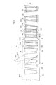
- FIG. 5 is a schematic configuration diagram showing a separation step and the like in the method for manufacturing an absorbent article according to the third embodiment.
- FIG. 6 is a schematic configuration diagram showing a method for manufacturing an absorbent article of the same example.
- FIG. 1 shows a first embodiment of an absorbent article (1), the absorbent article (1) comprising a liquid-permeable top sheet (2), a liquid-impermeable back sheet (3), And an absorber (4) disposed between the two sheets (2, 3).
- the top sheet (2) may be liquid permeable, and preferably a porous or non-porous nonwoven fabric or a porous plastic sheet is used to cover the surface of the absorbent body (4).
- the material fibers constituting the nonwoven fabric synthetic fibers, natural fibers such as recycled fibers and cotton can be adopted, and nonwoven fabrics obtained by known processing methods such as a spunlace method and a thermal bond method are used. be able to.
- the backsheet (3) only needs to have liquid impermeability so that the body fluid absorbed by the absorbent body does not leak to the outside.
- a laminated nonwoven fabric obtained by laminating a nonwoven fabric on a polyethylene sheet or the like is used.
- a material having moisture permeability is preferably used from the viewpoint of preventing stuffiness.
- the absorbent body (4) is formed of fluff pulp, air laid nonwoven fabric or the like, and may contain a water-absorbing polymer. Body fluids such as menstrual blood discharged from the wearer are absorbed by the absorbent body (4) through the top sheet (2).
- a diffusion sheet (not shown) may be disposed between the top sheet (2) and the absorber (4).
- the diffusion sheet is formed of, for example, a non-woven fabric that has been subjected to a hydrophilic treatment, whereby body fluid flowing from the top sheet (2) side spreads on the surface of the absorber (4) and is quickly absorbed by the absorber (4).
- a carrier sheet (not shown) formed of, for example, a tissue or a nonwoven fabric may be disposed.
- the carrier sheet has a continuous web shape in the manufacturing process, and the absorbent body (4) is intermittently disposed on the carrier sheet and conveyed.
- a pair of three-dimensional cuffs (15) (also referred to as a side sheet).
- the three-dimensional cuff (15) is formed of, for example, a water-repellent or hydrophobic nonwoven fabric and rises three-dimensionally. Thereby, the side leakage of body fluid is prevented.
- this absorbent article (1) is formed in a trapezoidal shape in plan view.
- the width (W5) of one end (5) in the longitudinal direction (L) is larger than the width (W6) of the other end (6).
- the wide end portion (5) is disposed on the back side of the body, and the narrow end portion (6) is disposed on the front side of the body so that the absorbent article (1) is worn by the wearer.
- the wearer's buttocks side is covered over a wide range at the wide end portion (5), and the intermediate portion (56) between the pair of end portions (5, 6) is covered.
- the width is not excessively wide. Therefore, a good fit will be obtained.
- the width of the absorbent article (1) in the width direction (W) is too small, it will be liable to shift when worn.
- the width of the absorbent article (1) in the width direction (W) is too large, a sense of incongruity will be generated at the time of wearing, and the fit will be lowered.
- the ratio (W5 / W6) of the width (W5) of the wide end portion (5) to the width (W6) of the narrow end portion (6) in the absorbent article (1) is preferable. May be set to 1.5 to 2.2, more preferably set to 1.6 to 2.1, and most preferably set to 1.7 to 2.0.
- the said absorber (4) is formed in the substantially trapezoid shape along the external shape of this absorbent article (1), Therefore The area of an absorber (4) becomes large.
- the width direction (W) of the width (W41) of one end (41) in the longitudinal direction (L) of the absorbent body (4) is larger than the width (W42) of the other end (42). Is also big. Thereby, a large amount of body fluid is quickly absorbed and held in the absorber (4). If the width of the absorbent body (4) in the width direction (W) is too small, the wearer's body fluid will not be sufficiently absorbed.
- the ratio (W41 / W42) of the width (W41) of the wide end (41) to the width (W42) of the narrow end (42) in the absorber (1) is preferably It may be set to 1.6 to 2.4, more preferably set to 1.7 to 2.3, and most preferably set to 1.8 to 2.2.
- the shape of this absorber (4) may not be the shape along the external shape of an absorbent article, for example, a planar view may be a rectangle or other arbitrary shapes.
- the manufacturing method of the said absorbent article (1) is a top sheet supply process (S1), an absorber supply process (S2), a back sheet supply process (S3), and a joining process (S4). ), A first separation step (S51), and a second separation step (S52).
- a continuous web (an example of a continuous sheet) (W3) forming the back sheet (3) is continuously supplied.
- the absorber supply step (S2) the absorber (4) is intermittently supplied by the intermittent supply device (7) onto the continuous web (W3) forming the back sheet (3).
- the supplied absorber (4) is arranged in a posture rotated 180 degrees with respect to the preceding absorber (4).
- the top sheet supply step (S1) the continuous web (an example of the continuous sheet) (W2) forming the top sheet (2) is the continuous web (W3) forming the back sheet (3) and the absorber (4). ) Continuously. That is, the absorber (4) is sandwiched between the two continuous webs (W2, W3).
- the continuous webs (W2, W3) are joined to each other by the joining device (9) with the absorber (4) sandwiched therebetween, and the continuous laminate (8). Is formed.
- the continuous laminate (8) is separated between the adjacent absorbers (4, 4) by the first cutting device (101). Are cut along the first cutting line (L1) and separated into individual absorbent articles (1).
- the continuous laminate (8) is moved between the adjacent absorbers (4, 4) by the second cutting device (102). Cut along two cutting lines (L2) and divided into individual absorbent articles (1).
- the first and second separation steps (S51, S52) will be described in detail.
- the first cutting line (L1) is the longitudinal direction (L) of the absorbent article (1) to be separated, that is, the continuous laminate (8). Inclined in the first direction with respect to the longitudinal direction (L).
- the continuous laminate (8) is cut along the first cutting line (L1), and the preceding absorbent article (1) is cut.
- the second cutting line (L2) upstream of the first cutting line (L1) is second in the longitudinal direction (L) of the continuous laminate (8). It is formed to be inclined in the direction.
- the continuous laminate (8) is cut along the second cutting line (L2), and the absorbent article (1) next to the preceding absorbent article (1) is cut. That is, the inclination direction of the first and second cutting lines (L1, L2) is the inclination of the cutting line when the absorbent article (1) is separated immediately before cutting the continuous laminate (8). It inclines to the opposite side centering on the said longitudinal direction (L) with respect to a direction.
- the first side portion (1S) is formed so as to form a predetermined angle B with respect to the longitudinal direction (L)
- the second side portion (2S) is formed so as to form a predetermined angle ⁇ B with respect to the longitudinal direction (L).
- both side portions (1S, 2S) are formed in a line-symmetric shape around a center line (CL) parallel to the longitudinal direction (L).
- CL center line
- L longitudinal direction
- each cutting line (L1, L2) is a continuous laminate ( It only needs to be inclined with respect to the longitudinal direction (L) of 8), and can be formed into an arbitrary curve.
- a cutting line may be formed in a curved shape that causes roundness to wait at the four corners of the absorbent article (1), thereby causing a slight cut loss.
- FIG. 4 shows a second embodiment of the absorbent article (1) of the present invention, wherein the both side portions (1S, 2S) are formed in a curved shape.
- the side portions (1S, 2S) are concave portions (12) recessed inward toward the absorber (4) in the intermediate portion (56) between the both end portions (5, 6).
- a convex portion (13) projecting to the outer side opposite to the inner side.
- the concave portion (12) and the convex portion (13) are point-symmetric with respect to the point O.
- the point O is set at a position corresponding to the center of the center line (CL) in each of the side portions (1S, 2S).
- the point O is set so that the length (L5) from one end (5) to the point O is equal to the length (L6) from the other end (6) to the point O.
- the width (W5) on one end (5) side is larger than the width (W6) on the other end (6) side, as in the first example.
- the wing (14) formed of the said convex part (13) has a shape which protruded to the side (outside of the width direction (W)) in the said both sides (1S, 2S).
- the outer shape of the absorbent body (4) disposed between the top sheet (2) and the back sheet (3) is such that the absorbent body (4) is reliably covered with both sheets (2, 3).
- the portions corresponding to the pair of recesses (12) are recessed toward the center of the absorbent article.
- Other configurations, manufacturing processes, and the like are the same as those in the first embodiment of the absorbent article (1) and operate in the same manner, and thus the description thereof is omitted.
- the continuous laminate (8) is cut into individual absorbent articles (1) by a cutting device (not shown).
- the absorbent article (1) has a cuff (15) extending in the longitudinal direction (L) at each side portion (1S, 2S) extending in the longitudinal direction (L).
- the absorbent article (1) has a line-symmetric structure around a center line (CL) that bisects the absorbent article (1) in the width direction (X) intersecting the longitudinal direction (L). ing.
- the outer side edge (15L) of the cuff (15) extends obliquely along the side portion.
- the one outer side edge (15L) is inclined and extended in the opposite direction to the other outer side edge (15L).
- the inner side edge (15M) of the cuff (15) is set to extend in parallel to the center line (CL). That is, the inner side edge (15M) extends in a direction orthogonal to the width direction (X).
- the width of the cuff (15) in the width direction (X) is such that the width (X1) of the cuff (15) on the wide end (5) side of the absorbent article (1) is that of the absorbent article (1). It is larger than the width (X2) of the cuff (15) on the end (6) side of the sandwich width. In other words, the width of the cuff (15) becomes narrower as it extends from the wide end (5) toward the narrow end (6).
- the back sheet is folded at both ends in the longitudinal direction (L) to form pockets (P).
- the other configuration is the same as that of the first embodiment of the absorbent article (1) and functions in the same manner, so that the description thereof is omitted.
- the second embodiment is a method for manufacturing the absorbent article (1) of the third embodiment.
- the manufacturing method of the said absorbent article (1) is a top sheet supply process (S1), an absorber supply process (S2), a back sheet supply process (S3), and a joining process (S4). ), A cuff placing step (S41), a continuous web folding step (S42), a first separation step (S51), and a second separation step (S52).
- a continuous web (an example of a continuous sheet) (W3) that forms the back sheet (3) of the absorbent article (1) is continuously supplied.
- the absorber (4) is intermittently supplied by an intermittent supply device (not shown) onto the continuous web (W3) forming the back sheet (3).
- the supplied absorber (4) is arranged in a posture rotated 180 degrees with respect to the preceding absorber (4).
- the continuous web (an example of the continuous sheet) (W2) that forms the top sheet (2) of the absorbent article (1) is the continuous web (W3) that forms the back sheet (3). And continuously supplied above the absorber (4).
- the absorber (4) is sandwiched between the two continuous webs (W2, W3).
- the width in the width direction (Y) intersecting the conveyance direction (F) of the continuous web (W2) forming the top sheet is the width in the direction (Y) of the continuous web (W3) forming the back sheet (3). Smaller than.
- the two continuous webs (W2, W3) are joined to each other by a joining device (not shown) with the absorber (4) sandwiched therebetween, so that the continuous laminate (8) is obtained. It is formed.
- the cuff members (15C) are intermittently placed on the continuous laminate (8) one after another so that the longitudinal direction (L) of the rectangular cuff members (15C) is orthogonal to the transport direction (F). Be placed.
- Each cuff member (15C) is arrange
- the width in the longitudinal direction (L) of the cuff member (15C) is smaller than the width in the width direction (Y) intersecting the transport direction (F) of the continuous web (W3).
- Each cuff member (15C) is cut into two cuffs (15) in a subsequent separation step. 5 and FIG. 6, the adhesion location of the cuff member (15C) is indicated by a halftone dot.
- the side edges (W31) of the continuous web (W3) forming the back sheet (3) are folded back. That is, a portion having a larger width than the continuous web (W2) and the cuff member (15C) in the width direction (Y) is folded back.
- the folded side edges (W31) overlap the continuous web (W2) and the cuff member (15C).
- the continuous laminated body (8) and the cuff member (15C) are separated by a first cutting device (not shown) between the absorbent bodies (4) adjacent to each other. L1), the one cuff member (15C) is cut into two cuffs (15), and the continuous laminate (8) is divided into individual absorbent articles (1) ( Carved). That is, in this step (S51), one cuff member (15C) is cut along the first cutting line (L1) extending obliquely with respect to the longitudinal direction (L) of the cuff member (15C). And cut into two cuffs (15). Specifically, the cuff member (15C) is cut into two cuffs (15) so that one cuff rotates 180 degrees with respect to the other cuff.
- the continuous laminated body (8) and the cuff member (15C) are second cut lines between the absorbent bodies (4) adjacent to each other by a second cutting device (not shown). Cut along (L2), the one cuff member (15C) is cut into two cuffs (15), and the continuous laminate (8) is divided into individual absorbent articles (1). . That is, in this step (S52), one cuff member (15C) is cut along the second cutting line (L2) extending obliquely with respect to the longitudinal direction (L) of the cuff member (15C). And cut into two cuffs (15). Specifically, the cuff member (15) is cut into two cuffs (15) so that one cuff rotates 180 degrees with respect to the other cuff.
- the absorber was arrange
- the absorber may be intermittently disposed on the continuous web forming the top sheet, or the absorber may be intermittently disposed and supplied on a carrier sheet (not shown). Good.
- the point O may be set so as to be different.
- the width of the continuous web serving as the back sheet may be equal to the width of the continuous web serving as the top sheet.
- the width in the longitudinal direction of the cuff member may be smaller than the width of the continuous web serving as the top sheet.
- the shape of the cuff member is not limited to a rectangle, and may be, for example, a rounded corner.
- the cuff member of the absorbent article of the present invention may have elasticity in the longitudinal direction. In this case, in the second embodiment of the manufacturing method, since the longitudinal direction of the cuff member is arranged so as to be orthogonal to the transport direction of the continuous laminate, the cuff member is inclined with respect to the transport direction. It is easier to place the cuff member than to place it.
- the absorbent article of the present invention is suitable for sanitary napkins, incontinence urine pads, and the like because it can be efficiently produced with little waste of materials, has excellent fit, and can improve absorption performance.
Landscapes
- Health & Medical Sciences (AREA)
- Epidemiology (AREA)
- Life Sciences & Earth Sciences (AREA)
- Engineering & Computer Science (AREA)
- Biomedical Technology (AREA)
- Vascular Medicine (AREA)
- Heart & Thoracic Surgery (AREA)
- Animal Behavior & Ethology (AREA)
- General Health & Medical Sciences (AREA)
- Public Health (AREA)
- Veterinary Medicine (AREA)
- Botany (AREA)
- Manufacturing & Machinery (AREA)
- Absorbent Articles And Supports Therefor (AREA)
Abstract
Description
前記吸収性物品の長手方向(L)の一方の端部(5)の幅(W5)が他方の端部(6)の幅(W6)よりも大きい。
すなわち、前記吸収体は、平面視で長方形であってもよいが、好ましくは、吸収性物品の外形に合わせて一方の端部の幅が他方の端部の幅よりも大きくてもよい。この場合、体液を素早く吸収でき、また、吸収量を多くできるなど、吸収性物品の高い吸収性能を発揮できる。
前記各カフの外側の側縁は前記側部に沿って斜めに延び、
前記各カフの内側の側縁は、前記長手方向に交差する幅方向に前記吸収性物品を2等分する中心線に対し平行に延びるように設定されていてもよい。
この場合、前記長手方向におけるカフの一方の端部の幅が他方の端部の幅よりも大きくなり、前記吸収性物品にカフをしっかりと取り付けることができるだろう。
前記トップシート(2)を形成する連続シート(W2)を供給するトップシート供給工程(S1)と、
前記複数の吸収性物品における個々の前記吸収体(4)を間欠的に供給する吸収体供給工程(S2)と、
前記バックシート(3)を形成する連続シート(W3)を供給するバックシート供給工程(S3)と、
前記複数の吸収体(4)を前記両連続シート(W2)、(W3)の間に挟み込んだ状態で、前記両連続シート(W2)、(W3)を互いに接合して連続積層体(8)を形成する接合工程(S4)と、
前記個々の吸収体のうち互いに隣り合う吸収体(4)の間で前記連続積層体(8)を前記長手方向(L)に対して第1の方向に傾斜した所定の1つの仮想の第1切断線(L1)に沿って切断して先行する1つの吸収性物品(1)を切り分ける第1分離工程(S51)と、
前記個々の吸収体のうち互いに隣り合う吸収体(4)の間で前記連続積層体(8)を前記長手方向(L)に対して前記1つの仮想の第1切断線(L1)とは反対側の第2の方向に傾斜した所定の別の仮想の第2切断線(L2)に沿って切断して前記先行する吸収性物品(1)の次の吸収性物品(1)を切り分ける第2分離工程(S52)とを備え、
前記第1分離工程(S51)と前記第2分離工程(S52)とを交互に繰り返して個々の吸収性物品(1)を得る。
前記切断により連続積層体から個分けされた吸収性物品は、長手方向の一方の端部の幅が他方の端部の幅よりも大きい形状となる。個分けされた先行する1つの吸収性物品は隣り合う次の吸収性物品に対し180度回転した姿勢となるので、前記切断の際にカットロスが無く、或いはカットロスの発生量が大幅に低減される。そのため、材料の無駄を少なく抑えて効率よく生産することができる。
また、前記吸収性物品の両端部の間の中間部において、前記各側部に一方の吸収体側へ凹んだ凹部および隣り合う吸収体側へ突出した凸部が形成されるように前記切断線の形状を設定してもよい。この場合、この一対の凸部により吸収性物品の両側部から側方(隣り合う吸収体側)へ突出するウイングを備える吸収性物品とすることができる。
前記トップシート(2)を形成する連続シート(W2)を供給するトップシート供給工程(S1)と、
前記複数の吸収性物品における個々の前記吸収体(4)を間欠的に供給する吸収体供給工程(S2)と、
前記バックシート(3)を形成する連続シート(W3)を供給するバックシート供給工程(S3)と、
前記複数の吸収体(4)を前記両連続シート(W2)、(W3)の間に挟み込んだ状態で、前記両連続シート(W2)、(W3)を互いに接合して連続積層体(8)を形成する接合工程(S4)と、
2n個のカフ(15)となる長方形状のn個のカフ部材(15C)の長手方向(L)が前記連続積層体(8)の搬送方向(F)に対して直交するように前記カフ部材(15C)を前記個々の吸収体のうち互いに隣り合う吸収体(4)の間において前記連続積層体(8)上に間欠的に次々に配置する工程(S41)と、
前記個々の吸収体のうち互いに隣り合う吸収体(4)の間で前記連続積層体(8)および前記カフ部材(15C)を前記長手方向(L)に対して第1の方向に傾斜した所定の1つの仮想の第1切断線(L1)に沿って切断して、前記n個のカフ部材(15C)のうちの1つのカフ部材(15C)を切り分けると共に、先行する1つの吸収性物品(1)を切り分ける第1分離工程(S51)と、
前記個々の吸収体のうち互いに隣り合う吸収体(4)の間で前記連続積層体(8)および前記カフ部材(15C)を前記長手方向(L)に対して前記1つの仮想の第1切断線(L1)とは反対側の第2の方向に傾斜した所定の別の仮想の第2切断線(L2)に沿って切断して、前記n個のカフ部材(15C)のうちの1つのカフ部材(15C)を切り分けると共に、前記先行する吸収性物品(1)の次の吸収性物品(1)を切り分ける第2分離工程(S52)とを備え、
前記第1分離工程(S51)と前記第2分離工程(S52)とを交互に繰り返して個々の吸収性物品(1)を得る。
図1は吸収性物品(1)の第1実施例を示し、本吸収性物品(1)は、液透過性のトップシート(2)と、液不透過性のバックシート(3)と、前記両シート(2、3)の間に配置された吸収体(4)とを備える。
前記トップシート(2)は液透過性であればよく、好ましくは有孔または無孔の不織布や多孔性プラスチックシートなどが用いられ、吸収体(4)の表面を覆っている。前記不織布を構成する素材繊維としては、合成繊維の他、再生繊維、綿等の天然繊維を採用することができ、スパンレース法やサーマルボンド法など、公知の加工法によって得られた不織布を用いることができる。
前記吸収体(4)は、フラッフパルプやエアレイド不織布等で形成され、吸水性の高分子ポリマーが含まれていてもよい。装着者から排出された経血等の体液は、トップシート(2)を通してこの吸収体(4)に吸収される。
前記吸収性物品(1)の幅方向(W)の幅が小さすぎると着用時にズレが生じ易いだろう。一方、前記吸収性物品(1)の幅方向(W)の幅が大きすぎると装着時に違和感が生じフィット性が低下するだろう。このような理由から、前記吸収性物品(1)における狭幅の端部(6)の幅(W6)に対する広幅の端部(5)の幅(W5)の比(W5/W6)は、好ましくは1.5~2.2に設定され、より好ましくは1.6~2.1に設定され、最も好ましくは1.7~2.0に設定されてもよい。
前記吸収体(4)の幅方向(W)の幅が小さすぎると着用者の体液を十分に吸収できないだろう。一方、前記吸収体(4)の幅方向(W)の幅が大きすぎると前記吸収体(4)が重くなるだろう。このような理由から、前記吸収体(1)における狭幅の端部(42)の幅(W42)に対する広幅の端部(41)の幅(W41)の比(W41/W42)は、好ましくは1.6~2.4に設定され、より好ましくは1.7~2.3に設定され、最も好ましくは1.8~2.2に設定されてもよい。
なお、本吸収体(4)の形状は吸収性物品の外形に沿った形状でなくてもよく、例えば平面視が長方形や他の任意の形状であってもよい。
図2に示すように、前記吸収性物品(1)の製造方法は、トップシート供給工程(S1)と、吸収体供給工程(S2)と、バックシート供給工程(S3)と、接合工程(S4)と、第1分離工程(S51)と、第2分離工程(S52)とを備える。
前記吸収体供給工程(S2)では、前記吸収体(4)がバックシート(3)を形成する前記連続ウエブ(W3)上に間欠供給装置(7)により間欠的に供給される。供給される吸収体(4)は先行する吸収体(4)に対し180度回転された姿勢で配置される。
前記トップシート供給工程(S1)では、前記トップシート(2)を形成する連続ウエブ(連続シートの一例)(W2)がバックシート(3)を形成する連続ウエブ(W3)および前記吸収体(4)の上方へ連続的に供給される。すなわち、前記吸収体(4)は前記両連続ウエブ(W2、W3)の間に挟み込まれる。
その後、図2および図3に示すように、第1分離工程(S51)において、前記連続積層体(8)が第1切断装置(101)により、互いに隣り合う吸収体(4,4)の間での第1切断線(L1)に沿って切断され、個々の吸収性物品(1)に個分けされる(切り分けられる)。続いて、図3に示すように、第2分離工程(S52)において、前記連続積層体(8)が第2切断装置(102)により、互いに隣り合う吸収体(4、4)の間において第2切断線(L2)に沿って切断され、個々の吸収性物品(1)に個分けされる。
図3に示すように、前記第1分離工程(S51)において、第1切断線(L1)は個分けされる吸収性物品(1)の長手方向(L)、即ち前記連続積層体(8)の長手方向(L)に対し第1の方向に傾斜して形成されている。この第1切断線(L1)に沿って前記連続積層体(8)が切断され、先行する1つの吸収性物品(1)が切り分けられる。一方、前記第2分離工程(S52)において、前記第1切断線(L1)よりも上流側の第2切断線(L2)は前記連続積層体(8)の長手方向(L)に対し第2の方向に傾斜して形成されている。この第2切断線(L2)に沿って前記連続積層体(8)が切断され、前記先行する吸収性物品(1)の次の吸収性物品(1)が切り分けられる。
すなわち、前記第1および第2切断線(L1、L2)の傾斜方向は、前記連続積層体(8)の切断ごとに、直前に吸収性物品(1)を個分けした際の切断線の傾斜方向に対し前記長手方向(L)を中心に反対側へ傾斜する。
換言すれば、図1に示すように、前記吸収性物品(1)において、前記長手方向(L)に対して所定の角度Bをなすように第1側部(1S)が形成され、一方、前記長手方向(L)に対して所定の角度-Bをなすように第2側部(2S)が形成される。
すなわち、長手方向(L)に平行な中心線(CL)を中心に両側部(1S、2S)が線対称の形状に形成されている。
この結果、個分けされた各吸収性物品(1)は、隣り合う吸収性物品(1)とは同形同大で先行する吸収性物品(1)に対し180度回転された姿勢となり、前記切断の際にカットロスを生じない。
本実施例において、前記各側部(1S、2S)は、前記両端部(5、6)の間の中間部(56)において、吸収体(4)側へ向かう内側に凹んだ凹部(12)と、前記内側とは反対側の外側へ突出した凸部(13)とを各々備えている。
前記凹部(12)と前記凸部(13)とは点Oを中心に互いに点対称の形状となっている。前記点Oは前記各側部(1S、2S)において中心線(CL)の中心に対応する位置に設定されている。すなわち、一方の端部(5)から前記点Oまでの長さ(L5)と他方の端部(6)から前記点Oまでの長さ(L6)とが等しくなるように前記点Oは設定されている。
本実施例の吸収性物品(1)は、前記第1実施例と同様、一方の端部(5)側の幅(W5)が他方の端部(6)側の幅(W6)よりも大きい。また、前記両側部(1S、2S)には、前記凸部(13)により形成されたウイング(14)が側方(幅方向(W)の外側)へ突出した形状となっている。
なお、トップシート(2)とバックシート(3)との間に配置された吸収体(4)の外形は、この吸収体(4)が両シート(2、3)で確実に覆われるように、前記一対の凹部(12)に対応した部位が吸収性物品の中央に向かって凹んだ形状となっている。
その他の構成や製造工程等は前記吸収性物品(1)の前記第1実施例と同様であり、同様に作用するので説明を省略する。
後述する第1および第2分離工程(S51、S52)において図示しない切断装置により連続積層体(8)が個々の吸収性物品(1)に切り分けられる。前記吸収性物品(1)は長手方向(L)に延びる各側部(1S、2S)において、前記長手方向(L)に延びるカフ(15)を有している。前記吸収性物品(1)は前記長手方向(L)に交差する幅方向(X)に前記吸収性物品(1)を2等分する中心線(CL)を中心とした線対称の構造となっている。
一方、前記カフ(15)の内側の側縁(15M)は前記中心線(CL)に対し平行に延びるように設定されている。すなわち、前記内側の側縁(15M)は前記幅方向(X)に直交する方向に延びている。
その他の構成は前記吸収性物品(1)の前記第1実施例と同様であり、同様に作用するので説明を省略する。
図6に示すように、前記吸収性物品(1)の製造方法は、トップシート供給工程(S1)と、吸収体供給工程(S2)と、バックシート供給工程(S3)と、接合工程(S4)と、カフを配置する工程(S41)と、連続ウエブを折り返す工程(S42)と、第1分離工程(S51)と、第2分離工程(S52)とを備える。
前記吸収体供給工程(S2)では、前記吸収体(4)が前記バックシート(3)を形成する前記連続ウエブ(W3)上に図示しない間欠供給装置により間欠的に供給される。供給される吸収体(4)は先行する吸収体(4)に対し180度回転された姿勢で配置される。
前記トップシート供給工程(S1)では、吸収性物品(1)のトップシート(2)を形成する連続ウエブ(連続シートの一例)(W2)がバックシート(3)を形成する連続ウエブ(W3)および前記吸収体(4)の上方へ連続的に供給される。すなわち、前記吸収体(4)は前記両連続ウエブ(W2、W3)の間に挟み込まれる。
前記トップシートを形成する連続ウエブ(W2)の搬送方向(F)に交差する幅方向(Y)における幅は前記バックシート(3)を形成する連続ウエブ(W3)の前記方向(Y)における幅よりも小さい。
各カフ部材(15C)は後の分離工程において2つのカフ(15)に切り分けられる。なお、図5および図6において前記カフ部材(15C)の接着箇所を網点で示す。
すなわち、本工程(S51)において、1つの前記カフ部材(15C)は前記カフ部材(15C)の前記長手方向(L)に対して斜めに延びる前記第1切断線(L1)に沿って切断されて2つのカフ(15)に切り分けられる。具体的には、1つのカフが他方のカフに対し180度回転した姿勢となるように前記カフ部材(15C)が2つのカフ(15)に切り分けられる。
すなわち、本工程(S52)において、1つの前記カフ部材(15C)は前記カフ部材(15C)の前記長手方向(L)に対して斜めに延びる前記第2切断線(L2)に沿って切断されて2つのカフ(15)に切り分けられる。具体的には、1つのカフが他方のカフに対し180度回転した姿勢となるように前記カフ部材(15)が2つのカフ(15)に切り分けられる。
また、別体のウイングを吸収性物品に取り付けてもよい。
また、前記吸収性物品の第2実施例において、一方の端部(5)から前記点Oまでの長さ(L5)と他方の端部(6)から前記点Oまでの長さ(L6)とが異なるように前記点Oを設定してもよい。
また、前記製造方法の第2実施例において、前記バックシートとなる連続ウエブの幅を前記トップシートとなる連続ウエブの幅と等しくなるようにしてもよい。
また、前記製造方法の第2実施例において、前記カフ部材の長手方向の幅は前記トップシートとなる連続ウエブの幅よりも小さくてもよい。
また、前記製造方法の第2実施例において、前記カフ部材の形状は長方形に限られず、例えば角にアールをつけたものでもよい。
また、本発明の吸収性物品のカフ部材は長手方向に伸縮性を有していてもよい。この場合、前記製造方法の第2実施例においては前記カフ部材の長手方向を前記連続積層体の搬送方向に対して直交するように配置するため、前記カフ部材を前記搬送方向に対して斜めに配置する場合に比べカフ部材を配置し易い。
5:一方の端部(広幅端部) 6:他方の端部(挟幅端部)
7:間欠供給装置 8:連続積層体 9:接合装置 101:第1切断装置 102:第2切断装置
12:凹部 13:凸部 14:ウイング 15:立体カフ(カフ) 15C:カフ部材 15M:カフの内側の側縁 15L:カフの外側の側縁
1S:第1側部 2S:第2側部 L1:第1切断線 L2:第2切断線
S1:トップシート供給工程 S2:吸収体供給工程 S3:バックシート供給工程S4接合工程 S41:カフ部材の配置工程 S42:折り返し工程 S51:第1分離工程 S52:第2分離工程
CL:中心線 L:連続積層体(8)の長手方向 P:ポケット
Claims (7)
- 液透過性のトップシート(2)と液不透過性のバックシート(3)との間に吸収体(4)が配置された吸収性物品であって、
前記吸収性物品の長手方向(L)の一方の端部(5)の幅(W5)が他方の端部(6)の幅(W6)よりも大きいことを特徴とする、吸収性物品。 - 前記吸収体(4)の一方の端部(41)の幅(W41)が他方の端部(42)の幅(W42)よりも大きい請求項1に記載の吸収性物品。
- 前記長手方向(L)に延びる前記吸収性物品の両側部(1S)、(2S)から前記長手方向(L)に交差する幅方向(W)の外側に向かって突出するウイング(14)を更に備える、請求項1に記載の吸収性物品。
- 前記吸収性物品の両端部(5)、(6)の中間部(56)に、吸収体(4)側へ向かう内側に凹んだ一対の凹部(12)と、前記内側とは反対の外側へ突出した一対の凸部(13)とを備える、請求項1に記載の吸収性物品。
- 前記吸収性物品は前記長手方向(L)に延びる各側部(1S)、(2S)において、前記長手方向に延びるカフ(15)を有し、
前記各カフ(15)の外側の側縁(15L)は前記側部に沿って斜めに延び、
前記各カフ(15)の内側の側縁(15M)は、前記長手方向(L)に交差する幅方向(X)に前記吸収性物品を2等分する中心線(CL)に対し平行に延びるように設定されている請求項1に記載の吸収性物品。 - 請求項1~4のいずれか1項に記載されたトップシート(2)、バックシート(3)および吸収体(4)を備えた複数の吸収性物品を連続的に製造する方法であって、
前記トップシート(2)を形成する連続シート(W2)を供給するトップシート供給工程(S1)と、
前記複数の吸収性物品における個々の前記吸収体(4)を間欠的に供給する吸収体供給工程(S2)と、
前記バックシート(3)を形成する連続シート(W3)を供給するバックシート供給工程(S3)と、
前記複数の吸収体(4)を前記両連続シート(W2)、(W3)の間に挟み込んだ状態で、前記両連続シート(W2)、(W3)を互いに接合して連続積層体(8)を形成する接合工程(S4)と、
前記個々の吸収体のうち互いに隣り合う吸収体(4)の間で前記連続積層体(8)を前記長手方向(L)に対して第1の方向に傾斜した所定の1つの仮想の第1切断線(L1)に沿って切断して先行する1つの吸収性物品(1)を切り分ける第1分離工程(S51)と、
前記個々の吸収体のうち互いに隣り合う吸収体(4)の間で前記連続積層体(8)を前記長手方向(L)に対して前記1つの仮想の第1切断線(L1)とは反対側の第2の方向に傾斜した所定の別の仮想の第2切断線(L2)に沿って切断して前記先行する吸収性物品(1)の次の吸収性物品(1)を切り分ける第2分離工程(S52)とを備え、
前記第1分離工程(S51)と前記第2分離工程(S52)とを交互に繰り返して個々の吸収性物品(1)を得る製造方法。 - 請求項5に記載されたトップシート(2)、バックシート(3)、吸収体(4)および一対のカフ(15)を備えた複数の吸収性物品を連続的に製造する方法であって、
前記トップシート(2)を形成する連続シート(W2)を供給するトップシート供給工程(S1)と、
前記複数の吸収性物品における個々の前記吸収体(4)を間欠的に供給する吸収体供給工程(S2)と、
前記バックシート(3)を形成する連続シート(W3)を供給するバックシート供給工程(S3)と、
前記複数の吸収体(4)を前記両連続シート(W2)、(W3)の間に挟み込んだ状態で、前記両連続シート(W2)、(W3)を互いに接合して連続積層体(8)を形成する接合工程(S4)と、
2n個のカフ(15)となる長方形状のn個のカフ部材(15C)の長手方向(L)が前記連続積層体(8)の搬送方向(F)に対して直交するように前記カフ部材(15C)を前記個々の吸収体のうち互いに隣り合う吸収体(4)の間において前記連続積層体(8)上に間欠的に次々に配置する工程(S41)と、
前記個々の吸収体のうち互いに隣り合う吸収体(4)の間で前記連続積層体(8)および前記カフ部材(15C)を前記長手方向(L)に対して第1の方向に傾斜した所定の1つの仮想の第1切断線(L1)に沿って切断して、前記n個のカフ部材(15C)のうちの1つのカフ部材(15C)を切り分けると共に、先行する1つの吸収性物品(1)を切り分ける第1分離工程(S51)と、
前記個々の吸収体のうち互いに隣り合う吸収体(4)の間で前記連続積層体(8)および前記カフ部材(15C)を前記長手方向(L)に対して前記1つの仮想の第1切断線(L1)とは反対側の第2の方向に傾斜した所定の別の仮想の第2切断線(L2)に沿って切断して、前記n個のカフ部材(15C)のうちの1つのカフ部材(15C)を切り分けると共に、前記先行する吸収性物品(1)の次の吸収性物品(1)を切り分ける第2分離工程(S52)とを備え、
前記第1分離工程(S51)と前記第2分離工程(S52)とを交互に繰り返して個々の吸収性物品(1)を得る製造方法。
Priority Applications (2)
| Application Number | Priority Date | Filing Date | Title |
|---|---|---|---|
| CN201480027272.9A CN105228567B (zh) | 2013-06-25 | 2014-06-13 | 吸收性物品及其制造方法 |
| JP2015523977A JP6422128B2 (ja) | 2013-06-25 | 2014-06-13 | 吸収性物品とその製造方法 |
Applications Claiming Priority (2)
| Application Number | Priority Date | Filing Date | Title |
|---|---|---|---|
| JP2013132282 | 2013-06-25 | ||
| JP2013-132282 | 2013-06-25 |
Publications (1)
| Publication Number | Publication Date |
|---|---|
| WO2014208363A1 true WO2014208363A1 (ja) | 2014-12-31 |
Family
ID=52141707
Family Applications (1)
| Application Number | Title | Priority Date | Filing Date |
|---|---|---|---|
| PCT/JP2014/065714 Ceased WO2014208363A1 (ja) | 2013-06-25 | 2014-06-13 | 吸収性物品とその製造方法 |
Country Status (3)
| Country | Link |
|---|---|
| JP (1) | JP6422128B2 (ja) |
| CN (1) | CN105228567B (ja) |
| WO (1) | WO2014208363A1 (ja) |
Cited By (2)
| Publication number | Priority date | Publication date | Assignee | Title |
|---|---|---|---|---|
| WO2017070530A1 (en) | 2015-10-23 | 2017-04-27 | Curt G. Joa, Inc. | Feminine hygiene products and apparatus and methods for making disposable products |
| CN112638338A (zh) * | 2018-09-26 | 2021-04-09 | 宝洁公司 | 用于制备可适应吸收制品的方法 |
Citations (10)
| Publication number | Priority date | Publication date | Assignee | Title |
|---|---|---|---|---|
| US2408508A (en) * | 1942-12-01 | 1946-10-01 | John P Canavan | Nonchafing catamenial pad |
| JPS56109660A (en) * | 1980-02-06 | 1981-08-31 | Uni Charm Corp | Sanitary napkin |
| JPH04300547A (ja) * | 1991-03-27 | 1992-10-23 | Zuikou:Kk | ウイング付き生理用ナプキンの製造方法 |
| JPH04352958A (ja) * | 1991-05-28 | 1992-12-08 | Zuikou:Kk | 立体サイドガード付き生理用ナプキンの製造方法 |
| JPH10511581A (ja) * | 1994-12-30 | 1998-11-10 | エスシーエー メールンリユーケ アーベー | 可撓性吸収性製品 |
| JP2002219144A (ja) * | 2000-11-21 | 2002-08-06 | Uni Charm Corp | 生理用ナプキン |
| JP2003526466A (ja) * | 2000-03-15 | 2003-09-09 | ザ、プロクター、エンド、ギャンブル、カンパニー | 改良された吸収性強化構造を持つソング衛生ナプキン |
| JP2007082576A (ja) * | 2005-09-20 | 2007-04-05 | Kao Corp | 吸収性物品 |
| JP2010188142A (ja) * | 2010-03-29 | 2010-09-02 | Daio Paper Corp | 吸収性物品の製造方法 |
| JP2011502569A (ja) * | 2007-11-06 | 2011-01-27 | エスセーアー・ハイジーン・プロダクツ・アーベー | 失禁プロテクターのための取り付け手段 |
Family Cites Families (6)
| Publication number | Priority date | Publication date | Assignee | Title |
|---|---|---|---|---|
| US20030208177A1 (en) * | 2000-03-15 | 2003-11-06 | D'alessio Nicola | Flexible sanitary napkin |
| SG96660A1 (en) * | 2000-11-21 | 2003-06-16 | Uni Charm Corp | Sanitary napkin |
| US20040087425A1 (en) * | 2002-10-31 | 2004-05-06 | Ng Tony C. | Process for applying portions of material to a moving web |
| CN101257873A (zh) * | 2005-09-09 | 2008-09-03 | 宝洁公司 | 具有侧翼活化作用的吸收制品 |
| JP5328438B2 (ja) * | 2008-03-31 | 2013-10-30 | ユニ・チャーム株式会社 | 吸収性物品の製造方法及び吸収性物品の製造装置 |
| JP5717581B2 (ja) * | 2011-08-03 | 2015-05-13 | ユニ・チャーム株式会社 | 吸収性物品の製造方法 |
-
2014
- 2014-06-13 JP JP2015523977A patent/JP6422128B2/ja not_active Expired - Fee Related
- 2014-06-13 CN CN201480027272.9A patent/CN105228567B/zh not_active Expired - Fee Related
- 2014-06-13 WO PCT/JP2014/065714 patent/WO2014208363A1/ja not_active Ceased
Patent Citations (10)
| Publication number | Priority date | Publication date | Assignee | Title |
|---|---|---|---|---|
| US2408508A (en) * | 1942-12-01 | 1946-10-01 | John P Canavan | Nonchafing catamenial pad |
| JPS56109660A (en) * | 1980-02-06 | 1981-08-31 | Uni Charm Corp | Sanitary napkin |
| JPH04300547A (ja) * | 1991-03-27 | 1992-10-23 | Zuikou:Kk | ウイング付き生理用ナプキンの製造方法 |
| JPH04352958A (ja) * | 1991-05-28 | 1992-12-08 | Zuikou:Kk | 立体サイドガード付き生理用ナプキンの製造方法 |
| JPH10511581A (ja) * | 1994-12-30 | 1998-11-10 | エスシーエー メールンリユーケ アーベー | 可撓性吸収性製品 |
| JP2003526466A (ja) * | 2000-03-15 | 2003-09-09 | ザ、プロクター、エンド、ギャンブル、カンパニー | 改良された吸収性強化構造を持つソング衛生ナプキン |
| JP2002219144A (ja) * | 2000-11-21 | 2002-08-06 | Uni Charm Corp | 生理用ナプキン |
| JP2007082576A (ja) * | 2005-09-20 | 2007-04-05 | Kao Corp | 吸収性物品 |
| JP2011502569A (ja) * | 2007-11-06 | 2011-01-27 | エスセーアー・ハイジーン・プロダクツ・アーベー | 失禁プロテクターのための取り付け手段 |
| JP2010188142A (ja) * | 2010-03-29 | 2010-09-02 | Daio Paper Corp | 吸収性物品の製造方法 |
Cited By (4)
| Publication number | Priority date | Publication date | Assignee | Title |
|---|---|---|---|---|
| WO2017070530A1 (en) | 2015-10-23 | 2017-04-27 | Curt G. Joa, Inc. | Feminine hygiene products and apparatus and methods for making disposable products |
| EP3364919A4 (en) * | 2015-10-23 | 2019-07-17 | Curt G. Joa, Inc. | FEMININE HYGIENE PRODUCTS AND APPARATUS AND METHODS FOR THE PRODUCTION OF DISPOSABLE PRODUCTS |
| US10729594B2 (en) | 2015-10-23 | 2020-08-04 | Curt G. Joa, Inc. | Feminine hygiene products and apparatus and methods for making disposable products |
| CN112638338A (zh) * | 2018-09-26 | 2021-04-09 | 宝洁公司 | 用于制备可适应吸收制品的方法 |
Also Published As
| Publication number | Publication date |
|---|---|
| CN105228567B (zh) | 2018-09-18 |
| JP6422128B2 (ja) | 2018-11-14 |
| CN105228567A (zh) | 2016-01-06 |
| JPWO2014208363A1 (ja) | 2017-02-23 |
Similar Documents
| Publication | Publication Date | Title |
|---|---|---|
| JP3953848B2 (ja) | パンツ型の使い捨ておむつ | |
| JP5065881B2 (ja) | パンツ型着用物品 | |
| JP5342879B2 (ja) | 吸収性物品 | |
| US20100179494A1 (en) | Absorptive article | |
| JP5250407B2 (ja) | 使い捨てパンツ型おむつおよびその製造方法 | |
| JP2010284418A (ja) | 吸収性物品 | |
| JP2011206331A (ja) | 吸収性物品及びその製造方法 | |
| JP2004159949A (ja) | トランクス型使い捨ておむつおよび該使い捨ておむつの製造方法 | |
| JP6265329B2 (ja) | 吸収性物品及びその製造方法 | |
| JP2010011911A (ja) | 吸収性物品 | |
| JP6459906B2 (ja) | 吸収性物品 | |
| JP6422128B2 (ja) | 吸収性物品とその製造方法 | |
| CN103957854B (zh) | 一次性穿用物品 | |
| JP3776014B2 (ja) | 吸収性物品およびその製造方法 | |
| JP6383723B2 (ja) | ウイング付き吸収性物品とその製造方法 | |
| JP5540380B2 (ja) | パンツ型使い捨ておむつ | |
| JP2011235020A (ja) | 使い捨ておむつ | |
| JP2010259500A (ja) | 男性用軽失禁パッド | |
| JP6443533B2 (ja) | 吸収性物品 | |
| JP4426785B2 (ja) | パンツ型の使い捨ておむつ | |
| JP2016209124A (ja) | 吸収性物品 | |
| WO2020137423A1 (ja) | 吸収性物品用の吸収体、及び吸収性物品 | |
| JP2009207516A (ja) | 吸収性物品 | |
| JP2009006024A (ja) | パンツ型使い捨ておむつの製造方法、及びパンツ型使い捨ておむつ | |
| JP2010104415A (ja) | ウエストベルトの製造方法及び使い捨ておむつの製造方法 |
Legal Events
| Date | Code | Title | Description |
|---|---|---|---|
| WWE | Wipo information: entry into national phase |
Ref document number: 201480027272.9 Country of ref document: CN |
|
| 121 | Ep: the epo has been informed by wipo that ep was designated in this application |
Ref document number: 14816740 Country of ref document: EP Kind code of ref document: A1 |
|
| ENP | Entry into the national phase |
Ref document number: 2015523977 Country of ref document: JP Kind code of ref document: A |
|
| NENP | Non-entry into the national phase |
Ref country code: DE |
|
| 122 | Ep: pct application non-entry in european phase |
Ref document number: 14816740 Country of ref document: EP Kind code of ref document: A1 |