WO2014208308A1 - 取引処理システム、取引処理方法 - Google Patents
取引処理システム、取引処理方法 Download PDFInfo
- Publication number
- WO2014208308A1 WO2014208308A1 PCT/JP2014/065004 JP2014065004W WO2014208308A1 WO 2014208308 A1 WO2014208308 A1 WO 2014208308A1 JP 2014065004 W JP2014065004 W JP 2014065004W WO 2014208308 A1 WO2014208308 A1 WO 2014208308A1
- Authority
- WO
- WIPO (PCT)
- Prior art keywords
- information
- unit
- transaction
- code
- instruction
- Prior art date
- Legal status (The legal status is an assumption and is not a legal conclusion. Google has not performed a legal analysis and makes no representation as to the accuracy of the status listed.)
- Ceased
Links
Images







Classifications
-
- G—PHYSICS
- G07—CHECKING-DEVICES
- G07F—COIN-FREED OR LIKE APPARATUS
- G07F19/00—Complete banking systems; Coded card-freed arrangements adapted for dispensing or receiving monies or the like and posting such transactions to existing accounts, e.g. automatic teller machines
- G07F19/20—Automatic teller machines [ATMs]
-
- G—PHYSICS
- G07—CHECKING-DEVICES
- G07F—COIN-FREED OR LIKE APPARATUS
- G07F19/00—Complete banking systems; Coded card-freed arrangements adapted for dispensing or receiving monies or the like and posting such transactions to existing accounts, e.g. automatic teller machines
- G07F19/20—Automatic teller machines [ATMs]
- G07F19/209—Monitoring, auditing or diagnose of functioning of ATMs
-
- G—PHYSICS
- G06—COMPUTING OR CALCULATING; COUNTING
- G06Q—INFORMATION AND COMMUNICATION TECHNOLOGY [ICT] SPECIALLY ADAPTED FOR ADMINISTRATIVE, COMMERCIAL, FINANCIAL, MANAGERIAL OR SUPERVISORY PURPOSES; SYSTEMS OR METHODS SPECIALLY ADAPTED FOR ADMINISTRATIVE, COMMERCIAL, FINANCIAL, MANAGERIAL OR SUPERVISORY PURPOSES, NOT OTHERWISE PROVIDED FOR
- G06Q10/00—Administration; Management
- G06Q10/20—Administration of product repair or maintenance
Definitions
- the present invention relates to a transaction processing system and a transaction processing method.
- ATMs Automatic Tellers Machine
- the ATM stores information at the time of failure.
- ATM is connected to the bank network, but generally, maintenance personnel who recover from ATM failure cannot access the bank network connected by a dedicated line, and the maintenance personnel network itself is connected to the bank network. It cannot be connected. Therefore, since information when a failure occurs inside the ATM cannot be obtained via the bank network, the maintenance staff goes directly to the site, and a portable storage medium such as a USB (Universal Serial Bus) memory is stored in the ATM. Connect to acquire data and perform failure analysis and repair based on that data.
- USB Universal Serial Bus
- connecting a portable storage medium such as a USB memory to the ATM is not desirable in terms of security, such as virus infection or unauthorized maintenance of the data in the ATM. Further, since it is necessary to unlock the ATM in order to connect the portable storage medium to the ATM, there is another security problem.
- the object of the present invention is to obtain ATM internal data at low cost while ensuring security.
- a transaction processing system is a transaction processing system having a transaction apparatus and an information processing apparatus, and the information processing apparatus is generated in the transaction apparatus.
- An input unit that receives an instruction for a fault, a conversion unit that encodes the instruction received by the input unit into a code, and a communication unit that transmits the code converted by the conversion unit to a terminal.
- the apparatus converts a device image capturing unit that captures a code displayed on the display unit of the terminal, a code captured by the device image capturing unit into a command corresponding to the instruction, and a process result executed by the command.
- a device conversion unit that converts information into a code for causing the terminal to read the information; a processing unit that executes the command and outputs information of the processing result; and A device display unit for displaying the code obtained by converting the distribution, configured as a transaction processing system characterized in that it comprises a.
- the present invention is grasped as a transaction processing method executed in the transaction processing system.
- FIG. 1 It is a figure which shows the structural example of the transaction processing system in this Embodiment. It is a general-view figure of ATM used with the transaction processing system shown in FIG. It is a block diagram which shows the function structure of each part which ATM has. It is a block diagram which shows the function structure of PC which a maintenance worker system has. It is a figure which shows the structural example of a portable terminal. It is a block diagram which shows the function structure which a portable terminal has. It is an image figure at the time of performing failure handling of ATM using a transaction processing system and a portable terminal. It is a flowchart which shows the process sequence of a failure process. It is a flowchart which shows the process sequence of the failure process when not using a two-dimensional code.
- FIG. 1 is a diagram illustrating a configuration example of a transaction processing system 1 in the present embodiment.
- the transaction processing system 1 in the present embodiment includes a bank transaction system 10, a maintenance staff system 20, and a mobile terminal 500.
- the bank transaction system 10 is a system that performs various account processing in response to a request from the ATM 100, and the ATM 100, the account host 200, and the support center 300 are connected via the bank network N1.
- the account host 200 is a computer that performs various processes related to bank operations.
- the support center 300 is a system for recovering from a failure when a failure occurs in the bank transaction system 10, and an in-house operator investigates and recovers the generated failure as much as possible.
- the maintenance personnel system 20 is a system for maintaining the bank transaction processing system 10, and is connected to the Internet N3 via a line connection unit (not shown).
- the maintenance staff system 20 is installed at a maintenance base, and a maintenance staff performs analysis and repair work of failures caused by ATM 100 failure or the like.
- the maintenance engineer system 20 and the network N3 are separately referred to as a maintenance engineer system 400.
- the maintenance engineer system 400 actually includes a PC 4001 that is operated by an expert who is proficient in handling a failure, and the PC 4001 is connected to the network N3.
- it is difficult to handle the failure in the company for example, when the recovery cannot be performed despite the investigation and the recovery at the support center 300 or the cause of the failure cannot be identified.
- an operator in the company or the like notifies the maintenance staff system 400, and an expert who is proficient in the failure analyzes the contents and generates instructions for dealing with the failure (such as various commands for the failure).
- the portable terminal 500 is a terminal that is operated by a maintenance person who receives an instruction from an expert, and actually performs a response when a failure occurs in the ATM 100. As shown in FIG. 1, the portable terminal 500 is connected to the ATM 100 and the maintenance personnel system 400 via the wireless communication network N2. Although specifically described later, the portable terminal 500 is a two-dimensional code (for example, QR code (registered trademark), barcode), an instruction for responding to the failure (for example, ATM1 output at the time of the failure) For example, a command for obtaining a log of this data, a command for recovering data, and the like) are read by a camera of the ATM 100.
- QR code registered trademark
- barcode an instruction for responding to the failure
- the ATM 100 executes processing related to the failure according to the two-dimensionally encoded command, outputs the result, and converts the result into the two-dimensional code, and displays these information on the display unit 5.
- the portable terminal 500 captures the contents (for example, command execution log and error code, two-dimensional code of these information, etc.), and transmits the image to the PC of the maintenance personnel system 400.
- an error code is received from 500 and displayed on the display unit, or when a two-dimensional code is received from the portable terminal 500, the two-dimensional code is converted into an error code and displayed on the display unit.
- Check In this way, the instruction corresponding to the failure is two-dimensionally encoded and read by the ATM 100 and executed, and the result is imaged and fed back to the maintenance engineer system 400. It is possible to reduce the risk that the data will be collected or the clerk will fraudulently fraudulent data.
- FIG. 2 is an overview of the ATM 100 used in the transaction processing system 1 shown in FIG.
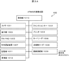
- FIG. 3A is a block diagram illustrating a functional configuration of each unit included in the ATM 100.
- the ATM 100 is an automatic transaction apparatus that is installed in a branch of a financial institution, a branch office, a convenience store, an unmanned store, etc., and performs transactions such as cash deposits and withdrawals by user operations. 200.
- the ATM 100 is a device that automatically executes various transactions requested by a user. As shown in FIGS. 2 and 3A, a camera 1001, a function key 1002, a display unit 1003, a printer 1004, a PINPAD 1005, and the like.
- the control unit 1010, the storage unit 1011 and the conversion unit 1012 include a hardware configuration such as a CPU and a memory, and a software configuration such as a program and data, and performs various processes. Specific processing performed by each part of the ATM 100 will be described later. Each part will be described below.
- the camera 1001 is installed in front of the ATM 100 and images the front of the ATM 100. For example, the camera 1001 captures a moving image and a still image of a user who makes a transaction with the ATM 100.
- the function key 1002 is installed on the front surface of the ATM 100 and has a function of accepting an input from a user, accepts designation of a transaction type (for example, withdrawal, deposit, etc.) and accepts a cancel operation thereof.
- There are a plurality of function keys 1002 (two on both sides of the display unit 1003 in the example shown in FIG. 2). When each function key 1002 is selected, a function corresponding to each function key 1002 is executed. Is displayed on the display unit 1003, and the function is executed.
- Display unit 1003 displays various screens.
- the display unit 1003 mainly displays a guidance screen for a transaction operation when a user of the ATM 100 performs a transaction, or displays a user operation such as a personal identification number or an input result of a key pressed by a finger.
- the display unit 1003 displays the execution result and the two-dimensional code of the execution result.
- the printer 1004 prints the transaction details on a statement slip and discharges it from the apparatus.
- the PINPAD 1005 has a function of accepting an input indicating a number from 0 to 9, and accepts an input of a personal identification number, an amount, an account number, and the like by a user.
- the card reader 1006 is a card insertion or ejection operation for a user to operate the ATM 100 to perform transaction processing, a magnetic stripe of the card, an IC chip read or write operation when the card is an IC card, card embossing Read a partial image.
- the biometric authentication device 1007 has a reading function for reading the biometric information of the user, and an authentication function between the biometric information registered in the IC card and the read biometric information.
- the non-contact reader 1008 detects the approach of the user's non-contact card, and reads or writes various information on the non-contact card.
- the line connection unit 1009 connects a line between the ATM 100 and the accounting host 200 or the support center 300. And as above-mentioned, the process of these each site
- the storage unit 1011 is a result of the transaction of the ATM 100 with the user, detailed log information when a failure occurs, an execution result when an instruction to deal with the failure that occurred in the ATM 100 is executed, The two-dimensional code of the execution result is stored.
- the conversion unit 1012 converts the execution result into a two-dimensional code. In the present embodiment, a case has been described in which the conversion unit 1012 of the ATM 100 converts the execution result of the instruction for dealing with the failure into a two-dimensional code and displays it on the display unit 1003.
- the card reader 1006 The execution result and the two-dimensional code are recorded on the IC card inserted into the IC card, the execution result and the two-dimensional code are recorded on the IC card via the non-contact reader 1008, and the execution result is also displayed by the printer 1004.
- a two-dimensional code may be printed on paper.
- the PC 4001 has a card reader and non-contact reader similar to those of the ATM 100, and a scanner for reading print information.
- a recording device for recording instructions on the above-described IC card is connected to the PC 4001, the instructions are recorded on the IC card without being two-dimensionally encoded, and the instructions are read by the card reader 1006 or the non-contact reader 1008 of the ATM 100. It is also possible to make it. Since the read instruction is executed and the execution result is recorded on the IC card, it is possible to obtain failure information while maintaining security even when the two-dimensional code cannot be used.
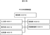
- FIG. 3B is a block diagram showing a functional configuration of a PC (personal computer) 4001 included in the maintenance engineer system 400.
- the PC 4001 includes an input unit 40011, a display unit 40012, a conversion unit 40013, a line connection unit 40014, a storage unit 40015, and a control unit 40010 that controls these units. It is configured.
- the input unit 40011 receives an input of an instruction for dealing with a failure occurring in the ATM 100 from an expert.
- the display unit 40012 displays an instruction input by the expert, a result of the conversion unit 40013 converting the instruction into a two-dimensional code, a processing result for failure handling executed by the ATM 100 according to an instruction from the expert, a two-dimensional code thereof, and the like.
- the conversion unit 40013 converts the instruction for failure handling generated by the expert into a two-dimensional code, or the processing result for fault handling executed by the ATM 100 according to the instruction from the expert and the original actual value from the two-dimensional code. Convert to error code or error information indicating the contents.
- the line connection unit 40014 connects the PC 4001 to the wireless network N2 or the network N3.
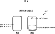
- the mobile terminal 500 includes a camera 5001, a display unit 5002, an operation unit 5003, a non-contact communication unit 5004, a communication unit 5005, and a storage unit 5006.
- the camera 5001 images the surroundings of the mobile terminal 500.
- an instruction, a processing result, or a two-dimensional code thereof is captured for handling a failure displayed on the display unit 1003 of the ATM 1 by an operation by a maintenance staff.
- the display unit 5002 displays various information including an image captured by the camera 5001, a two-dimensional code transmitted from the PC 4001, or various operations for dealing with a failure occurring in the ATM 100.
- the operation unit 5003 receives an operation such as pressing of a button displayed on the display unit 5002 or a touch operation from a maintenance staff.
- the non-contact communication unit 5004 communicates with the non-contact reader 1008 of the ATM 100 in a non-contact manner.
- a communication unit 5005 performs telephone calls and message transmission / reception.
- the storage unit 5006 stores various information including images captured by the camera 5001, the above-described two-dimensional code, and various operations for dealing with a failure that has occurred in the ATM 100.
- the main control unit 5010 controls the operation of each unit.
- FIG. 6 is an image diagram when dealing with a failure of the ATM 100 using the transaction processing system 1000 and the portable terminal 500.
- a maintenance center outside the bank maintenance personnel system 20
- an ATM 100 that constitutes the bank transaction system 10 and a support center 300 within the bank.
- the ATM 100 is installed in a bank branch or the like as described above, and is connected to the support center 300 in the bank through a dedicated bank network N1.
- the maintenance center constituting the maintenance center 20 outside the bank is not connected to the bank network N1 such as a dedicated line, but is connected to a staff network N3 such as the Internet.
- the expert uses the portable terminal 500 such as a mobile phone to contact the maintenance staff, notifies the ATM location and instructions for dealing with the fault, or the maintenance staff from the failure information (such as failure of the ATM) For example, an error code or log information generated at that time is acquired.
- the maintenance staff rushes to the ATM according to the instruction of the expert, acquires the failure information from the ATM, or restores the failure state of the ATM.
- failure information such as an error code at the time of the failure is notified from the support center in the bank to the maintenance staff, and the maintenance staff notifies the maintenance center 200 of the failure information.
- the input unit 40011 of the PC 4001 accepts an input of an instruction (for example, a command for recovering the failure) by the operation of (1), and the conversion unit 40013 receives the received instruction in two dimensions. It is converted into a code (2), and the two-dimensional code is transmitted to the portable terminal 500 of the maintenance person via the line connection unit 40014 (3).
- the maintenance staff operates the portable terminal 500 that he / she owns, and the main control unit 5010 displays the two-dimensional code received via the communication unit 5005 on the display unit 5002 (4), and the camera 1001 of the ATM 100
- the two-dimensional code is imaged and read (5).
- the biometric authentication device 1007 performs authentication using the finger vein of the maintenance person and permits execution of the instruction.
- the control unit 1010 of the ATM 100 executes an instruction
- the conversion unit 1012 converts the execution result into a two-dimensional code (6), and displays the result on the display unit 1003 (7).
- the biometric authentication device 1007 of the ATM 100 reads and authenticates the finger vein, but the same function may be given to the portable terminal 500.
- the portable terminal 500 receives an operation from the maintenance staff, the camera 5001 reads the execution result of the instruction displayed on the display unit 1003 of the ATM 100 and its two-dimensional code (8), and these are transmitted via the communication unit 5005.
- Information is transmitted to the PC 4001 of the maintenance center (9).
- the conversion unit 40013 of the PC 4001 displays an execution result corresponding to the instruction transmitted from the maintenance staff, or converts the two-dimensionally encoded execution result to be displayed on the display unit 40012.
- the expert confirms the contents. , Check the results for the instructions you gave.
- FIG. 7 is a flowchart illustrating a processing procedure of failure processing.
- FIG. 8 shows a processing procedure of failure processing when a two-dimensional code is not used, and is the same as each processing in FIG. 7 except for the processing of S311, S320, S321, and S330.
- the PC 4001 receives an input of an instruction created by an expert (for example, a command for collecting information from the fault ATM) (S201).
- This instruction includes, for example, a number that uniquely designates the ATM, an error code to be acquired and a failure detailed log file name of each unit, a time limit at which information can be acquired from the ATM, and the like.
- the conversion unit 40013 analyzes the content of the instruction, converts the instruction into a two-dimensional code, and transmits the converted two-dimensional code to the portable terminal 500 of the maintenance worker (S202, S203).
- the portable terminal 500 of the maintenance worker S202, S203.
- conventionally known various methods can be used for the conversion to the two-dimensional code.
- the portable terminal 500 receives the two-dimensional code transmitted from the PC 4001 via the communication unit 5005 (S210), and the main control unit 5010 displays the received two-dimensional code on the display unit 5002 on the portable terminal 500. At this time, the portable terminal 500 is tricked into the camera 1001 of the ATM 100 by an operation from the maintenance staff, and the camera 1001 captures the two-dimensional code (S211).
- the conversion unit 1012 of the ATM 100 reads the two-dimensional code picked up by the camera 5001 and converts it into an instruction sentence input by the expert to the PC 4001 (S220), and a command for responding to the fault according to the instruction by the control unit 1010 ( For example, a command for collecting logs from each unit in the ATM 100 is executed, and the conversion unit 1012 converts the execution result (for example, the collected log) into a two-dimensional code as failure information, and the execution result and the two-dimensional code are converted into the two-dimensional code.
- the information is displayed on the display unit 1003 (S221).
- the camera 5001 of the portable terminal 500 images the execution result and the two-dimensional code displayed on the display unit 1003 of the ATM 100 by an operation from the maintenance staff (S230), and transmits these pieces of information to the PC 4001 (S231).
- the conversion unit 40013 converts the two-dimensional code into failure information before conversion and displays the information on the display unit 40012 (S240). Then, the expert confirms the failure information displayed on the display unit 40012, analyzes the failure, and the input unit 40011 receives an instruction to be performed next from the expert. Thereafter, each process from S201 to S240 is repeated to recover the failure.
- the conversion unit 40013 when receiving an instruction to output fault information from the expert to the ATM 100, the conversion unit 40013 converts the instruction into a two-dimensional code.
- the instruction is given to a one-dimensional code or a numeric string.
- failure information that is converted and read from the ATM 100 may be designated. Since the one-dimensional code represents a number, in these cases, the one-dimensional code or number received by the portable terminal 500 from the PC 4001 instead of imaging the display unit 5002 of the portable terminal 500 on which the camera 5001 of the ATM 100 is deceived.
- the PINPAD 1005 receives an input operation from the maintenance staff, and a number is input (S311 in FIG. 8).
- the instruction may be executed (S320, S321) and output to an IC card, magnetic card, or non-contact card (S330) as will be described later.
- a table in which the one-dimensional code or number and the instruction are associated in advance is stored in the storage unit 1011 and the instruction is specified by the input one-dimensional code or number.
- the instruction described above is recorded on the IC card or the magnetic card, and is inserted into the card reader 1006 of the ATM 100.
- an instruction may be specified for the ATM 100 using the inserted IC card or magnetic card, and the conversion unit 1012 may read and execute the instruction.
- an instruction is recorded in the contactless card or the contactless communication unit 5004 of the portable terminal, the instruction is specified using the contactless card reader of the ATM unit, and the conversion unit 1012 reads and executes the instruction. May be.
- the IC card, magnetic card, or contactless card in which the instruction is recorded may be directly delivered to the maintenance staff, or the data including the instruction may be recorded on the card by the maintenance staff.
- the conversion unit 40013 converts the above-described instructions into the operation buttons and order of the function keys 1002, transmits the operation buttons and order to the portable terminal 500, receives the operation buttons and order from the maintenance staff, and gives the instructions.
- the operation buttons, the order of the function keys 1002, and the instructions are stored in the storage unit 1011 in advance in association with each other.
- a time limit is set for the ATM 100 to output failure information, and the control unit 1010 of the ATM 100 is within that time (for example, a time other than business hours).
- the failure information may be output during the time zone, and the failure information may not be output outside the time zone. In this case, the capacity of the storage unit 1011 can be reduced, and it is possible to prevent troubles such as bank staff from acquiring trouble information at unnecessary timing.
- the failure information converted by the conversion unit 1012 may be a one-dimensional code or a string of numbers instead of the two-dimensional code, as in the case of the PC 4001.
- the information is printed from the printer 1004 instead of the display unit 1003, the IC card or the magnetic card inserted into the card reader 1006, the non-contact card close to the non-contact reader 1008, the mobile terminal 500 It may be output to the non-contact communication unit 5004. In this way, failure information can be received even when the camera 5001 of the mobile terminal 500 is faulty or not installed.
- contents specifying the device to be output as an output destination may be included in the instruction and converted into a two-dimensional code.
- the designation of the output destination may be designated by the conversion unit 40013 when the input unit 40011 of the PC 4001 receives an instruction from an expert. Further, the output destination may be selected when the main control unit 5010 of the portable terminal 500 designates an instruction to the ATM. In this way, for example, even if the maintenance worker's portable terminal 500 does not have the camera 5001 or the non-contact communication unit 5004, the failure information is output to the designated output destination by the control unit 1010 of the ATM 100. The maintenance staff can receive the failure information.
- FIG. 9 is a flowchart showing the processing procedure of the authentication processing.
- the PC 4001 inputs the biometric information (for example, finger vein image) of the maintenance staff stored in the PC 4001 in addition to the instruction created by the expert (for example, a command for collecting information from the fault ATM). Accept (S401). Since the contents of this instruction are the same as those shown in FIGS. 7 and 8, the description thereof is omitted here.
- the conversion unit 40013 analyzes the content of the instruction, converts the instruction and the biological information into a two-dimensional code, and converts the converted two-dimensional code into the portable terminal 500 of the maintenance staff. (S402, S403). As in the case shown in FIGS. 7 and 8, various conventionally known methods can be used for conversion to a two-dimensional code.
- the portable terminal 500 performs the same processing as S210 and S211 in FIGS. 7 and 8 (S410 and S411), a maintenance person places a biometric (for example, a finger) on the biometric authentication device 1007 of the ATM 100, and the biometric authentication device 1007 performs maintenance.
- a biometric for example, a finger
- the biological information for example, finger vein
- the conversion unit 1012 of the ATM 100 converts the instruction text input by the expert to the PC 4001 (S420), determines whether the two-dimensional code captured by the camera 5001 includes biological information of the maintenance staff, When it is determined that the biological information of the maintenance staff is included, the biological information read in S412 is compared with the biological information included in the two-dimensional code (S421).
- the control unit 1010 issues a command for dealing with the failure according to the converted instruction (for example, a command for collecting logs from each unit in the ATM 100). Execute. Then, the conversion unit 1012 converts the execution result (for example, collected logs) into a two-dimensional code as failure information, and displays the execution result and the two-dimensional code on the display unit 1003 (S422). On the other hand, when the conversion unit 1012 determines that the two pieces of biological information do not match, the control unit 1010 ends the process without outputting the failure information.
- the conversion unit 1012 determines that both pieces of biometric information match
- the control unit 1010 ends the process without outputting the failure information.
- the camera 5001 of the portable terminal 500 captures the execution result and the two-dimensional code displayed on the display unit 1003 of the ATM 100 by the operation from the maintenance staff, and stores the information on the PC 4001. Transmit (S430, S431, S440).
- the expert confirms the failure information displayed on the display unit 40013, analyzes the failure, and the input unit 40011 receives an instruction to be performed next from the expert. Thereafter, each process from S401 to S440 is repeated to recover the failure.
- each process from S401 to S440 is repeated to recover the failure.
- authentication using finger veins has been described as an example of authentication using biometric information.
- biometric authentication information for example, fingerprint authentication or palm vein
- the PINPAD 1005 accepts input of alphanumeric characters or the like defined as a password.
- the maintenance personnel's biometric information is converted into a two-dimensional code on the PC 4001 side and transmitted to the portable terminal 500, but is stored in advance in the ATM 100 or the biometric authentication device 1007. It is also possible to authenticate the maintenance person himself / herself by comparing the living body information with the living body information included in the two-dimensional code.
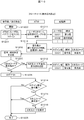
- FIG. 10 is a flow in the case of performing processing for preventing maintenance personnel from forgetting to display the two-dimensional code.
- the flowchart relevant to the process sequence which ATM100 displays a two-dimensional code on the display part 1003 is shown.
- the maintenance staff usually performs maintenance work other than the process of reading the two-dimensional code. For example, replacement of a faulty part, replacement of a cassette for storing banknotes, replenishment of consumables such as printer paper. Since these are accesses to the inside of the ATM, the ATM 100 has a login processing function for accepting access only by authorized maintenance personnel. The login processing function is performed by the conversion unit 1012.
- the ATM 100 receives an input of a user ID and a password for determining whether it is a regular maintenance person or not (S1201).
- access to the ATM 100 is not limited to maintenance personnel, and bank clerk may also access, so the login processing function can be processed for bank clerk.
- bank clerk can turn off and on the ATM and replenish consumables, but does not perform advanced maintenance such as replacement of failed parts. For this reason, display of the two-dimensional code of the ATM 100, imaging of the displayed two-dimensional code, and data transmission of the captured two-dimensional code are performed only by maintenance personnel and not by bank staff in this example.
- the ATM 100 stores the user ID handled by the login processing function in advance in the storage unit 1011 in association with the type information indicating whether it is a maintenance worker or a bank clerk as shown in FIG.
- An operator maintenance person or bank clerk (hereinafter referred to as “login”) inputs a user ID and password to the ATM 100, and the conversion unit 1012 performs login processing (S1201).
- the conversion unit 1012 of the ATM 100 refers to the storage unit based on the input user ID (S1211), and determines whether the logged-in user ID is a maintenance worker ID or a bank clerk ID.
- the conversion unit 1012 stores the result in the storage unit 1011 as history data in which the login ID is associated with the type (S1212).
- the login person After logging in to the ATM 100, the login person performs processing such as maintenance work and replenishment work (S1202).
- processing such as maintenance work and replenishment work (S1202).
- the conversion unit 1012 of the ATM 100 converts the two-dimensional code into the two-dimensional code.
- the display information that is displayed and that indicates the display is stored in the storage unit 1011 as history data in association with the login ID of the login user (S1213).
- the login person executes a logout process from the ATM 100 (S1204).
- the conversion unit 1012 of the ATM 100 determines whether the login person is a maintenance person based on the login ID (S1214). If the logged-in person is a bank clerk (S1214-No), the user is logged out normally and the process ends (S1205). When the login person is a maintenance person (S1214-Yes), the conversion unit 1012 refers to the history data based on the login ID, and the display information of the two-dimensional code is displayed (present) or not displayed (not present). Is determined (S1215). If the two-dimensional code has already been displayed (S1215-Yes), the user logs out normally and ends (S1205).
- the two-dimensional code obtained by encoding the processing result information is displayed on the display unit 1003 of the ATM 100 (S1216), and then the process ends (S1205).
- the ATM receives an instruction to display the two-dimensional code from the maintenance staff.
- step S1214 at the time of logout, it is determined whether it is a maintenance worker or a bank clerk. This is determined at a timing after step S1212 such as between step S1202 and step 1203, and depending on the determination result. It is good also as control which displays a two-dimensional code compulsorily.
- two types of log-in persons work types
- maintenance personnel and bank clerks are provided. For example, a type such as an administrator or a skilled bank clerk who can perform maintenance work is provided, and the judgment is made corresponding to the login ID. You may make it do.
- FIG. 11 is a flow in the case of performing processing for preventing maintenance personnel from imaging and forgetting to transmit a two-dimensional code.
- the ATM 100 displays a two-dimensional code on the display unit 1003, shows a flowchart related to a processing procedure for capturing and transmitting with the camera 5001 of the mobile terminal 500.
- the maintenance staff inputs the user ID and password to the ATM 100 and performs login processing (S1301).
- the maintenance staff performs maintenance work and replenishment work after login processing to the ATM 100 (S1302).
- the maintenance staff instructs the display unit 1003 of the ATM 100 to display a two-dimensional code obtained by encoding the processing result information (S1303-Yes)
- the conversion unit 1012 of the ATM 100 displays the two-dimensional code (S1311).
- the maintenance staff images the displayed two-dimensional code with the portable terminal 500 (S1304).
- a logout process is executed from the ATM 100 (S1305).
- the conversion unit 1012 of the ATM 100 displays a release code input screen on the display unit 1003, and a code (hereinafter referred to as logout) required for logout.
- the maintenance staff is urged to input “cancel code” (S1312). If the maintenance person forgets to capture the two-dimensional code obtained by encoding the processing result information in step S1304 (S1306-No), the ATM instructs the ATM to display the two-dimensional code.
- the conversion unit 1012 of the ATM 100 displays the two-dimensional code again (S1313), and the maintenance person images the two-dimensional code with the portable terminal 500 (S1307).
- the maintenance staff transmits the captured two-dimensional code from the portable terminal 500 to the expert's PC 4001 (S1308).
- the conversion unit 40013 of the expert PC 4001 generates a release code using the two-dimensional code received from the maintenance worker's portable terminal 500 (S1321), and transmits the generated release code to the maintenance worker's portable terminal 500 (S1322). ).
- the maintenance staff inputs the received release code to the release code input screen of ATM 100 (S1309).
- the two-dimensional code is not transmitted to the expert's PC or the release code is received from the expert's PC due to the failure of the mobile terminal or the communication failure.
- the maintenance staff may be able to input a predetermined fixed code for logout (hereinafter referred to as “master code”) separately from the release code.
- master code a predetermined fixed code for logout
- the conversion unit 1012 of the ATM 100 determines whether the input cancellation code is the cancellation code transmitted from the expert PC 4001 or the master code (S1314). If the input release code is a master code (S1314-Yes), the conversion unit 1012 stores the date and time information and user ID at which the master code is input in the storage unit 1011 (S1315). By storing the user ID, history information for specifying maintenance personnel who frequently use the master code can be obtained.
- the maintenance staff can urge the maintenance staff to reliably execute the processing of imaging the two-dimensional code and transmitting the two-dimensional code to the expert PC necessary for receiving the release code. Further, by storing the date and time information, the possibility that the master code has to be input due to a communication failure can be verified by failure analysis.
- the logout process from the ATM 100 is completed. In this way, it is possible to prevent maintenance personnel from forgetting to capture the two-dimensional code and forgetting to transmit the two-dimensional code. Further, when the ATM 100 accepts the master code input, the maintenance staff can finish the work by inputting the master code even if communication failure occurs.
- the maintenance person's portable terminal 500 transmits the two-dimensional code captured in step S1308 to the expert PC 4001. However, even if the two-dimensional code is displayed and transmitted to the expert PC 4001 at step S1304 when the image is captured. good. Further, it is possible to omit the two-dimensional code display instruction in step S1303 and to always display the two-dimensional code at the time of step S1306.
- the conversion unit 1012 of the ATM 100 may determine whether the cancellation code is correct and logout from the ATM 100 only when it is correct. Further, the flow of FIG. 10 and FIG. 11 may be executed together to display the two-dimensional code and input the release code only when the maintenance staff is logged in. In this case, the display of the two-dimensional code and the display of the release code can be controlled using a login with the maintenance personnel ID as a trigger.
- the present invention is not limited to the above-described embodiments, and includes various modifications.
- the above-described embodiments have been described in detail for easy understanding of the present invention, and are not necessarily limited to those having all the configurations described.
- a part of the configuration of one embodiment can be replaced with the configuration of another embodiment, and the configuration of another embodiment can be added to the configuration of one embodiment.
- the printer 1004 included in the ATM 100 may be a printer connected to another information processing apparatus via a network.
- the control unit 1010 transmits the two-dimensional code converted by the conversion unit 1012 to the printer.
- the output may be from a printer other than the ATM 100 (for example, a printer used by a branch clerk).
- the PINPAD 1005 and the biometric authentication device 1007 do not have to be included in the ATM 100 main body, and may be connected by a cable or the like.
- the function of each part of the portable terminal 500 may be included in the PC 4001 or the function of each part of the PC 4001 may be included in the portable terminal 500 to configure the transaction processing system 1 as one device. In this case, for example, when both an expert and a maintenance staff are employed, each job can be performed with one terminal.
Landscapes
- Business, Economics & Management (AREA)
- Physics & Mathematics (AREA)
- General Physics & Mathematics (AREA)
- Accounting & Taxation (AREA)
- Human Resources & Organizations (AREA)
- Engineering & Computer Science (AREA)
- Finance (AREA)
- Entrepreneurship & Innovation (AREA)
- Economics (AREA)
- Marketing (AREA)
- Operations Research (AREA)
- Quality & Reliability (AREA)
- Strategic Management (AREA)
- Tourism & Hospitality (AREA)
- General Business, Economics & Management (AREA)
- Theoretical Computer Science (AREA)
- Financial Or Insurance-Related Operations Such As Payment And Settlement (AREA)
- Management, Administration, Business Operations System, And Electronic Commerce (AREA)
Abstract
Description
図10は、保守員の2次元コードの表示忘れを防止するための処理を行う場合のフローである。ATM100が表示部1003に2次元コードを表示する処理手順に関連するフローチャートを示す。
図10に示す実施の例では、保守員は、通常、2次元コードを読み出す処理以外の保守作業も実施する。例えば故障部品の交換、紙幣を格納するカセットの交換、プリンタ用紙など消耗品の補充などである。これらはATM内部へのアクセスであるため、ATM100は、正規の保守員のみアクセスを受け付けるログイン処理機能を備える。ログイン処理機能は、変換部1012によって行われる。ATM100は、正規の保守員かそうでないかを判断するためのユーザIDとパスワードの入力を受ける(S1201)。一方、ATM100にアクセスするのは保守員とは限らず、銀行係員もアクセスすることがあるため、ログイン処理機能は、銀行係員についても処理可能である。一般に銀行係員はATMの電源のオフとオン、消耗品の補充は可能だが、故障部品の交換などの高度な保守作業は実施しない。このためATM100の2次元コードの表示、表示された2次元コードの撮像、撮像した2次元コードのデータ送信は、本例では保守員のみが実施し、銀行係員は実施しないこととする。
ATM100は、ログイン処理機能で扱うユーザIDについて、図10に示すように記憶部1011に保守員か銀行係員かを示す種別情報と対応させてあらかじめ記憶しておく。操作者たる保守員または銀行係員(以下「ログイン者」とする)は、ATM100に対してユーザIDとパスワードを入力し、変換部1012がログイン処理する(S1201)。ATM100の変換部1012は、入力されたユーザIDに基づいて記憶部を参照し(S1211)、ログイン処理したユーザIDが保守員のIDか銀行係員のIDかを判断する。変換部1012は、その結果を、ログインIDと種別とを対応させた履歴データとして記憶部1011に格納する(S1212)。ログイン者は、ATM100にログイン後、保守作業や補充作業などの処理を行う(S1202)。
ここで、ログイン者が、ATM100の表示部1003に処理結果情報をコード化した2次元コードを表示させるようATM100に指示処理した場合(S1203-Yes)、ATM100の変換部1012は当該2次元コードを表示し、かつ表示したことを表す表示情報をログイン者のログインIDと対応させて履歴データとして記憶部1011に格納する(S1213)。
ログイン者が作業を終える時、ログイン者はATM100からのログアウト処理を実行する(S1204)。ここでATM100の変換部1012は、ログインIDに基づいてログイン者が保守員かどうかを判断する(S1214)。ログイン者が銀行係員である場合(S1214-No)は、正常にログアウトし、終了する(S1205)。ログイン者が保守員である場合(S1214-Yes)は、変換部1012は、ログインIDに基づいて履歴データを参照し、2次元コードの表示情報が表示済(有り)か、表示未済(無し)かを判断する(S1215)。2次元コードを表示済である場合(S1215-Yes)は、正常にログアウトし、終了する(S1205)。2次元コードを表示済でない場合(S1215-No)は、ATM100の表示部1003に処理結果情報をコード化した2次元コードを表示し(S1216)、その後、終了する(S1205)。
このようにすることで、高度な保守作業を実施する保守員と、実質的に保守作業を実施しない銀行係員の、ATMに2種類以上のログイン者種別(作業種別)がある状態において、高度な保守作業を実施する保守員に対して、保守処理の進捗状況確認や完了確認に必要な2次元コードを確実に出力させ、ATMに表示させることができる。
なお、ステップS1203においてATMが保守員から2次元コードの表示指示を受けることとしたが、これを省略し、ステップS1215の時点でATM100が2次元コードを必ず表示する制御としても良い。また、ログアウト時のステップS1214に、保守員か銀行係員かを判断するようにしたが、これをステップS1202とステップ1203の間などのステップS1212以降のタイミングで判断しておき、判断結果に応じて2次元コードを強制的に表示する制御としても良い。
この実施例では、保守員と銀行係員の2つのログイン者種別(作業種別)としたが、例えば管理者や、保守作業が行える熟達した銀行係員などの種別を設け、ログインIDと対応させて判断するようにしても良い。
また、保守員か銀行係員かの判断をユーザIDにより判断しているが、例えばステップS1202の作業において、保守員のみが実施するような作業指示をATM100が受けた場合に、保守員であると判断するように制御しても良い。
図11は、保守員の2次元コードの撮像および送信忘れを防止するための処理を行う場合のフローである。ATM100が表示部1003に2次元コードを表示し、携帯端末500のカメラ5001で撮像し、送信する処理手順に関連するフローチャートを示す。
保守員はATM100に対してユーザIDとパスワードを入力し、ログイン処理をする(S1301)。保守員は、ATM100にログイン処理後、保守作業や補充作業などを行う(S1302)。ここで保守員がATM100の表示部1003に処理結果情報をコード化した2次元コードを表示指示した場合(S1303-Yes)、ATM100の変換部1012は、当該2次元コードを表示する(S1311)。保守員は表示された2次元コードを携帯端末500により撮像する(S1304)。
しかし、保守員によっては、この2次元コードの撮像を忘れて2次元コードを表示させるのみであったり、または2次元コードの表示も忘れるということが起こりうる。これらの場合には、エキスパート側のPCに障害情報が届かないため、保守作業の進捗確認や完了確認ができなくなる。このような事態の防止のために、以下のステップを実行する。
保守員が作業を終える時はATM100からログアウト処理を実行する(S1305)が、このとき、ATM100の変換部1012は、解除コード入力画面を表示部1003に表示し、ログアウトに必要なコード(以下、「解除コード」とする)の入力を保守員に促す(S1312)。ここで保守員がステップS1304にて処理結果情報をコード化した2次元コードの撮像を忘れている場合(S1306-No)、ATMに対して当該2次元コードの表示指示を行う。このときATM100の変換部1012は、2次元コードを改めて表示し(S1313)、保守員は携帯端末500により2次元コードを撮像する(S1307)。
保守員は撮像した2次元コードを携帯端末500からエキスパートのPC4001へ送信する(S1308)。エキスパートのPC4001の変換部40013は、保守員の携帯端末500から受信した2次元コードを用いて、解除コードを生成し(S1321)、生成した解除コードを保守員の携帯端末500へ送信する(S1322)。保守員は受信した解除コードをATM100の解除コード入力画面に入力する(S1309)。
ここで、携帯端末の故障や通信不良などにより、エキスパートのPCへの2次元コードの送信またはエキスパートのPCからの解除コードの受信が正常に行えない場合がある。これに備えるため、保守員は解除コードとは別に、ログアウトのための予め定められた固定のコード(以下「マスタコード」とする)が入力できるようにしてもよい。ATM100の変換部1012は、入力された解除コードが、エキスパートのPC4001から送信された解除コードか、マスタコードかを判断する(S1314)。入力された解除コードがマスタコードの場合(S1314-Yes)は、変換部1012は、マスタコードが入力された日時情報とユーザIDを記憶部1011に格納する(S1315)。ユーザIDの格納により、マスタコードを多用する保守員を特定するための履歴情報が得られる。これにより、解除コードの受信に必要な、2次元コードの撮像及び2次元コードのエキスパートPCへの送信の処理の確実な実行を保守員に促すことが可能となる。また、日時情報の格納により、通信障害によりマスタコードを入力せざるを得なかった可能性について障害分析にて検証が可能となる。解除コードもしくはマスタコードのATM100への入力を受けると、ATM100からのログアウトの処理は完了する。
このようにすることで、保守員の2次元コードの撮像忘れおよび2次元コードの送信忘れの防止を図ることができる。また、ATM100がマスタコード入力を受け付ける場合は、通信不良などの事態になってもマスタコードを入力することで保守員が作業を終了できる。
ここで、保守員の携帯端末500はステップS1308で撮像した2次元コードをエキスパートのPC4001に送信したが、2次元コードが表示され、撮像したステップS1304の時点で、エキスパートのPC4001に送信しても良い。またステップS1303の2次元コード表示指示を省略し、ステップS1306の時点で2次元コードを必ず表示する制御としても良い。またステップS1314にて、ATM100の変換部1012が解除コードの正誤判断を行い、正しい場合のみATM100からログアウトする制御としても良い。
また、図10と図11のフローを合わせて実行し、保守員がログインしているときにのみ2次元コードを表示させ、かつ、解除コードを入力させるようにしても良い。この場合は2次元コードの表示と解除コードの表示を、保守員IDでのログインをトリガーとして制御することができる。
10 銀行取引システム
20 保守員システム
100 ATM
1001 カメラ
1002 ファンクションキー
1003 表示部
1004 プリンタ
1005 PINPAD
1006 カードリーダ
1007 生体認証装置
1008 非接触リーダ
1009 回線接続部
1010 制御部
1011 記憶部
1012 変換部
200 勘定系ホスト
300 サポートセンタ
4001 PC
40011 入力部
40012 表示部
40013 変換部
40014 回線接続部
40015 記憶部
40010 制御部
500 携帯端末
5001 カメラ
5002 表示部
5003 操作部
5004 非接触通信部
5005 通信部
5006 記憶部
Claims (15)
- 取引装置と情報処理装置とを有する取引処理システムであって、
前記情報処理装置は、
前記取引装置に生じた障害に対する指示を受け付ける入力部と、
前記入力部が受け付けた前記指示をコードにコード化する変換部と、
前記変換部が変換した前記コードを端末に送信する通信部と、を備え、
前記取引装置は、
前記端末の表示部に表示されるコードを撮像する装置撮像部と、
前記装置撮像部が撮像したコードを前記指示に対応するコマンドに変換し、また前記コマンドによって実行された処理結果の情報を前記端末に読み込ませるためのコードに変換する装置変換部と、
前記コマンドを実行して前記処理結果の情報を出力する処理部と、
前記処理結果の情報を変換した前記コードを表示する装置表示部と、
を備えることを特徴とする取引処理システム。 - 前記変換部は、前記指示を2次元コード、1次元コード、数字のいずれかに変換することを特徴とする請求項1に記載の取引処理システム。
- 前記情報処理装置は、前記変換部が前記指示を1次元コード、数字のいずれかに変換し、
前記取引装置は、前記2次元コード、1次元コード、数字のいずれかの入力を受け付ける入力部と、前記指示と入力される前記1次元コード、数字のいずれかとを対応付けるテーブルを記憶する記憶部とを有し、
前記装置変換部は、前記入力された前記1次元コード、数字のいずれかと前記テーブルとに基づいて前記指示を特定し、前記処理部は特定された前記指示を実行する、
ことを特徴とする請求項1に記載の取引処理システム。 - 前記情報処理装置は、前記装置変換部が前記指示を変換する際に、前記取引装置が前記処理結果の情報を出力する時間制限を示す情報を前記指示と共に出力し、
前記取引装置は、前記処理部が前記指示を実行する際に、前記時間制限された時間帯であるか否かを判定し、前記時間制限された時間帯である場合に前記処理結果の情報を出力する、
ことを特徴とする請求項1乃至3のいずれかに記載の取引処理システム。 - 前記情報処理装置は、前記指示を媒体に記録する記録部と、前記処理結果の情報を読み取る読取部とをさらに備え、
前記取引装置は、前記装置撮像部に代えて、前記指示が記録された媒体を読み取るリーダ部を備え、前記処理部は前記リーダ部が読み取った前記指示を実行し、前記処理結果の情報を前記媒体に記録するよう処理する、
ことを特徴とする請求項1または4に記載の取引処理システム。 - 前記取引装置は、前記障害情報を印字する印字部をさらに備えることを特徴とする請求項1乃至5のいずれかに記載の取引処理システム。
- 前記取引装置は、前記端末との間で非接触により通信する装置非接触通信部をさらに備え、前記障害情報を前記装置非接触通信部を介して前記携帯端末に送信する、
ことを特徴とする請求項3または4に記載の取引処理システム。 - 前記変換部は、前記障害情報の出力先と前記指示とを2次元コードに変換し、
前記処理部は、前記コマンドを実行して前記出力先に前記処理結果の情報を出力させる、
ことを特徴とする請求項1乃至7のいずれかに記載の取引処理システム。 - 前記取引装置は、前記端末を操作する保守員の生体情報を認証する認証部を備え、
前記変換部は、前記情報処理装置に保存された前記保守員の生体情報と前記指示とを2次元コードに変換し、
前記認証部は、前記2次元コードに含まれる前記保守員の生体情報と、前記認証部が取得した生体情報とに基づいて前記保守員を認証し、
前記処理部は、前記保守員が認証された場合に、前記処理結果の情報を出力する、
ことを特徴とする請求項1乃至8のいずれかに記載の取引処理システム。 - 前記取引装置は、所定のパスワードの入力を受け付ける入力装置を備え、
前記処理部は、前記入力装置に入力されたパスワードが正しいと判定された場合に、前記処理結果の情報を出力する、
ことを特徴とする請求項1または4に記載の取引処理システム。 - 前記取引装置は、前記処理結果の情報を変換したコードの前記装置表示部での表示の有無についての表示情報と操作者のログインの際のユーザIDとを対応付けて記憶し、前記操作者のログアウトの際に前記ユーザIDに基づいて前記表示情報が無しと判断する場合に、前記装置表示部に前記処理結果の情報を変換したコードを表示することを特徴とする請求項1乃至10のいずれかに記載の取引処理システム。
- 前記ユーザIDは、前記操作者の種別情報と対応して設定されることを特徴とする請求項11に記載の取引処理システム。
- 前記情報処理装置は、前記端末が読み取った前記処理結果の情報を変換したコードを前記端末から受信する場合に、前記端末に前記保守員の前記取引装置からのログアウトに用いるコードを送信し、
前記取引装置は、前記保守者のログインと前記ログアウトとの処理を行い、前記ログアウトでは前記ログアウトに用いるコードの入力を受けるときに前記ログアウトの処理を行うことを特徴とする請求項1乃至12のいずれかに記載の取引処理システム。 - 取引装置と情報処理装置と端末とを用いる取引処理方法であって、
前記取引装置に生じた障害に対する指示を前記情報処理装置が受け付けるステップと、
前記指示を前記情報処理装置がコードにコード化するステップと、
前記コードを前記情報処理装置が前記端末に送信するステップと、 前記端末が受信した前記コードを前記端末の表示部に表示するステップと、
前記表示部に表示された前記コードを前記取引装置が撮像するステップと、
前記撮像した前記コードを前記指示に対応するコマンドに前記取引装置が変換する第1の装置変換のステップと、
前記コマンドを実行した処理結果の情報を前記取引装置が出力するステップと、
前記処理結果の情報をコードに変換する第2の装置変換のステップと、
前記第2の装置変換ステップで変換された前記コードを前記取引装置が表示するステップと、
前記前記取引装置が表示した前記コードを前記端末が撮像するステップと、
前記端末が撮像した前記コードを前記端末が前記情報処理装置に送信するステップと、
を含むことを特徴とする取引処理方法。 - 前記情報処理装置は、前記指示を2次元コード、1次元コード、数字のいずれかに変換することを特徴とする請求項14に記載の取引処理方法。
Priority Applications (1)
| Application Number | Priority Date | Filing Date | Title |
|---|---|---|---|
| JP2015523952A JP5985749B2 (ja) | 2013-06-27 | 2014-06-05 | 取引処理システム、取引処理方法 |
Applications Claiming Priority (2)
| Application Number | Priority Date | Filing Date | Title |
|---|---|---|---|
| JP2013-134579 | 2013-06-27 | ||
| JP2013134579 | 2013-06-27 |
Publications (1)
| Publication Number | Publication Date |
|---|---|
| WO2014208308A1 true WO2014208308A1 (ja) | 2014-12-31 |
Family
ID=52141654
Family Applications (1)
| Application Number | Title | Priority Date | Filing Date |
|---|---|---|---|
| PCT/JP2014/065004 Ceased WO2014208308A1 (ja) | 2013-06-27 | 2014-06-05 | 取引処理システム、取引処理方法 |
Country Status (3)
| Country | Link |
|---|---|
| JP (1) | JP5985749B2 (ja) |
| CN (1) | CN104252602B (ja) |
| WO (1) | WO2014208308A1 (ja) |
Cited By (4)
| Publication number | Priority date | Publication date | Assignee | Title |
|---|---|---|---|---|
| WO2018003505A1 (ja) * | 2016-06-29 | 2018-01-04 | グローリー株式会社 | 貨幣処理システム |
| JP2018124738A (ja) * | 2017-01-31 | 2018-08-09 | 沖電気工業株式会社 | 情報通信システム、情報通信方法、通信端末、現金処理装置及び通信プログラム |
| JP2020087000A (ja) * | 2018-11-27 | 2020-06-04 | 日立オムロンターミナルソリューションズ株式会社 | 取引端末装置および取引端末装置の取引制御方法 |
| JP2020087438A (ja) * | 2018-11-14 | 2020-06-04 | 大日本印刷株式会社 | 本人認証システム、認証器、プログラム及び本人認証方法 |
Families Citing this family (3)
| Publication number | Priority date | Publication date | Assignee | Title |
|---|---|---|---|---|
| JP7362372B2 (ja) * | 2019-09-05 | 2023-10-17 | 日立チャネルソリューションズ株式会社 | 紙幣処理システムの遠隔保守システム、および遠隔保守方法 |
| JP7442473B2 (ja) * | 2021-03-04 | 2024-03-04 | 株式会社日立ビルシステム | 入退室管理システム及び入退室管理方法 |
| CN115871745B (zh) * | 2022-12-28 | 2024-05-10 | 江苏安防科技有限公司 | 一种应用于轨道交通的智能维护方法与装置 |
Citations (3)
| Publication number | Priority date | Publication date | Assignee | Title |
|---|---|---|---|---|
| JPH0744635A (ja) * | 1993-07-27 | 1995-02-14 | Hitachi Ltd | 自動取引装置の保守方法 |
| JP2007257325A (ja) * | 2006-03-23 | 2007-10-04 | Oki Electric Ind Co Ltd | 自動取引装置監視システムおよび自動取引装置 |
| US20130086465A1 (en) * | 2011-10-04 | 2013-04-04 | Wesley John Boudville | Barcode and cellphone for privacy and anonymity |
Family Cites Families (4)
| Publication number | Priority date | Publication date | Assignee | Title |
|---|---|---|---|---|
| JP4109291B2 (ja) * | 2006-02-17 | 2008-07-02 | 日立オムロンターミナルソリューションズ株式会社 | 自動取引装置 |
| JP2009110148A (ja) * | 2007-10-29 | 2009-05-21 | Oki Electric Ind Co Ltd | 自動取引装置、自動取引システム及び自動取引装置の動作方法 |
| CN101344980B (zh) * | 2008-08-21 | 2011-01-19 | 中国工商银行股份有限公司 | 一种atm设备安全检测系统及方法 |
| JP5359792B2 (ja) * | 2009-11-02 | 2013-12-04 | セイコーエプソン株式会社 | 例外処理管理装置、例外処理管理装置の制御方法およびプログラム |
-
2014
- 2014-06-05 JP JP2015523952A patent/JP5985749B2/ja not_active Expired - Fee Related
- 2014-06-05 WO PCT/JP2014/065004 patent/WO2014208308A1/ja not_active Ceased
- 2014-06-13 CN CN201410264501.0A patent/CN104252602B/zh not_active Expired - Fee Related
Patent Citations (3)
| Publication number | Priority date | Publication date | Assignee | Title |
|---|---|---|---|---|
| JPH0744635A (ja) * | 1993-07-27 | 1995-02-14 | Hitachi Ltd | 自動取引装置の保守方法 |
| JP2007257325A (ja) * | 2006-03-23 | 2007-10-04 | Oki Electric Ind Co Ltd | 自動取引装置監視システムおよび自動取引装置 |
| US20130086465A1 (en) * | 2011-10-04 | 2013-04-04 | Wesley John Boudville | Barcode and cellphone for privacy and anonymity |
Cited By (7)
| Publication number | Priority date | Publication date | Assignee | Title |
|---|---|---|---|---|
| WO2018003505A1 (ja) * | 2016-06-29 | 2018-01-04 | グローリー株式会社 | 貨幣処理システム |
| JP2018005385A (ja) * | 2016-06-29 | 2018-01-11 | グローリー株式会社 | 貨幣処理システム |
| JP2018124738A (ja) * | 2017-01-31 | 2018-08-09 | 沖電気工業株式会社 | 情報通信システム、情報通信方法、通信端末、現金処理装置及び通信プログラム |
| JP2020087438A (ja) * | 2018-11-14 | 2020-06-04 | 大日本印刷株式会社 | 本人認証システム、認証器、プログラム及び本人認証方法 |
| JP7310522B2 (ja) | 2018-11-14 | 2023-07-19 | 大日本印刷株式会社 | 本人認証システム、認証器、プログラム及び本人認証方法 |
| JP2020087000A (ja) * | 2018-11-27 | 2020-06-04 | 日立オムロンターミナルソリューションズ株式会社 | 取引端末装置および取引端末装置の取引制御方法 |
| JP7171388B2 (ja) | 2018-11-27 | 2022-11-15 | 日立チャネルソリューションズ株式会社 | 取引端末装置および取引端末装置の取引制御方法 |
Also Published As
| Publication number | Publication date |
|---|---|
| CN104252602B (zh) | 2017-06-13 |
| JP5985749B2 (ja) | 2016-09-06 |
| CN104252602A (zh) | 2014-12-31 |
| JPWO2014208308A1 (ja) | 2017-02-23 |
Similar Documents
| Publication | Publication Date | Title |
|---|---|---|
| JP5985749B2 (ja) | 取引処理システム、取引処理方法 | |
| CN101783039B (zh) | 金融交易安全控制方法及终端 | |
| JP4221385B2 (ja) | 生体認証装置、端末装置及び自動取引装置 | |
| JP7230074B2 (ja) | 認証システムおよび情報処理方法 | |
| US20080178263A1 (en) | Network output system and registration method of authentication information | |
| WO2009152677A1 (zh) | 一种支付系统及其支付方法 | |
| US20120030107A1 (en) | Generation And Use Of Transaction Records With Imaging | |
| CN1952985B (zh) | Ic卡内认证系统 | |
| CN1959750B (zh) | 现金自动存取系统及装置 | |
| JP7556212B2 (ja) | 処理装置 | |
| CN218446808U (zh) | 智能政务服务终端 | |
| JP2021144657A (ja) | 情報収集支援プログラム、情報収集支援方法および情報処理装置 | |
| JP2006330957A (ja) | 本人確認システム | |
| JP4901606B2 (ja) | 生体情報登録システム、仮カード発行装置、生体情報登録装置、及び生体情報の登録方法 | |
| JP4500834B2 (ja) | Icカード内認証システム | |
| KR101734156B1 (ko) | 이동 통신 단말을 이용한 전자 문서 시스템 및 그 처리 방법 | |
| JP2007280405A (ja) | 本人認証方法 | |
| JP7391910B2 (ja) | 伝票業務支援方法、伝票業務支援システム、及び伝票業務支援装置 | |
| JP4564943B2 (ja) | 生体認証装置、端末装置及び自動取引装置 | |
| JP2007052687A (ja) | 現金自動取引システム | |
| JP6652889B2 (ja) | 自動取引装置 | |
| JP4208014B2 (ja) | 自動取引装置及び自動取引システム | |
| JP2008047143A (ja) | 自動取引システム | |
| KR100895642B1 (ko) | 금융자동화기기 | |
| JP4637132B2 (ja) | 指静脈登録方法、及び、指静脈登録装置 |
Legal Events
| Date | Code | Title | Description |
|---|---|---|---|
| 121 | Ep: the epo has been informed by wipo that ep was designated in this application |
Ref document number: 14816827 Country of ref document: EP Kind code of ref document: A1 |
|
| ENP | Entry into the national phase |
Ref document number: 2015523952 Country of ref document: JP Kind code of ref document: A |
|
| WWE | Wipo information: entry into national phase |
Ref document number: IDP00201508411 Country of ref document: ID |
|
| NENP | Non-entry into the national phase |
Ref country code: DE |
|
| 122 | Ep: pct application non-entry in european phase |
Ref document number: 14816827 Country of ref document: EP Kind code of ref document: A1 |