WO2014208237A1 - 綴じ具 - Google Patents
綴じ具 Download PDFInfo
- Publication number
- WO2014208237A1 WO2014208237A1 PCT/JP2014/063800 JP2014063800W WO2014208237A1 WO 2014208237 A1 WO2014208237 A1 WO 2014208237A1 JP 2014063800 W JP2014063800 W JP 2014063800W WO 2014208237 A1 WO2014208237 A1 WO 2014208237A1
- Authority
- WO
- WIPO (PCT)
- Prior art keywords
- teeth
- tooth
- paper
- inclined surface
- binding tool
- Prior art date
- Legal status (The legal status is an assumption and is not a legal conclusion. Google has not performed a legal analysis and makes no representation as to the accuracy of the status listed.)
- Ceased
Links
Images



















Classifications
-
- B—PERFORMING OPERATIONS; TRANSPORTING
- B42—BOOKBINDING; ALBUMS; FILES; SPECIAL PRINTED MATTER
- B42B—PERMANENTLY ATTACHING TOGETHER SHEETS, QUIRES OR SIGNATURES OR PERMANENTLY ATTACHING OBJECTS THERETO
- B42B5/00—Permanently attaching together sheets, quires or signatures otherwise than by stitching
Definitions
- the present invention relates to a binding tool that does not use a metal needle among binding tools that integrally bind the ends of a plurality of stacked sheets.
- a binding tool of this type a part of a sheet, which is arranged by stacking a plurality of sheets between a pair of teeth contacting and separating in a certain direction, is bound by compressing the sheet in the thickness direction by the teeth.
- Patent Document 1 a part of a sheet, which is arranged by stacking a plurality of sheets between a pair of teeth contacting and separating in a certain direction, is bound by compressing the sheet in the thickness direction by the teeth.
- the conventional one has a problem that the operation force applied to the operation handle becomes excessive in order to compress the paper so as to exhibit a holding force of a certain level or more.
- the operation handle is operated within a practical operating force range, there is a problem that the holding force between the sheets is not practical.
- Such problems are not limited to manually operating the operation handle, and a large-capacity actuator is required even when operated electrically.
- an object of the present invention is to provide a binding tool capable of securing a holding power of a certain level or more while keeping energy required for operation low.
- the binding tool according to the present invention includes a pair of teeth that contact and separate in a certain direction, and an inclined surface portion that forms a predetermined inclination angle with respect to the contact and separation direction.
- a binding tool capable of binding these sheets by press-contacting a part of the sheets arranged by laminating a plurality of sheets between the teeth at the surface portion with accompanying expansion of the sheet material, (1)
- the absolute value of the inclination angle with respect to the contact / separation direction of the teeth of the inclined surface portion is less than 38 °
- the length of the normal corresponding to the shortest distance between the inclined surface portions of the pair of teeth is 0.09 mm
- the length of the main pressure contact area formed by the two inclined surface portions in a direction perpendicular to the normal line is less than 0.18 mm in the state of being close to each other
- the elongation rate of the paper material exceeds 1.32 and 1 Satisfy at least one of 60 or less It is characterized in.
- paper material is a concept indicating the whole material constituting the paper, and includes paper, plastic fibers, and the like.
- the “main pressure contact area” is a portion where the sheet is most compressed between the inclined surface portions of the teeth. Specifically, when both the inclined surface portions are flat, the inclined surface portions face each other, In the case where at least one of the inclined surface portions is linear or dot-like, it indicates the closest portion between the inclined surface portions.
- each tooth includes a plurality of crest-side curved portions forming a tooth crest, a plurality of trough-side curved portions forming a trough of teeth, and ends and trough-side curved surfaces of these crest-side curved portions.
- a plurality of the inclined surface portions formed continuously between the end portions of the portions, and a tooth surface having a corrugated cross section is formed by the mountain side curved surface portion, the valley side curved surface portion, and the inclined surface portion.
- the absolute value of the inclination angle with respect to the tooth contact / separation direction of the inclined surface portion is preferably 25 ° or more and less than 38 °.
- the length is preferably more than 0 mm and less than 0.18 mm.
- the elongation rate of the paper material is preferably 1.36 or more and 1.47 or less.
- a half of the length of the mountain side curved surface portion along the corrugation is equal to or longer than the length of the inclined surface portion along the corrugation. More preferably, the half of the length along the waveform of the peak side curved surface portion and the length along the waveform of the inclined surface portion are equal.
- the length along the waveform of the mountain side curved surface portion is a concept indicating the length of the geodesic line from the apex of the mountain side curved surface portion to the boundary with the inclined surface portion.
- the length along the waveform of the inclined surface portion is a concept indicating the shortest distance between the boundary between the mountain side curved surface portion and the boundary between the valley side curved surface portion.
- the bound paper can ensure a certain level of holding force while keeping the energy required for operation low.
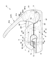
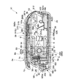
- FIG. 4 is a sectional view taken along line AA in FIG. 3.
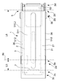
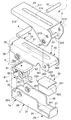
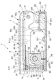
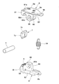
- the front view of the binding tool. The disassembled perspective view of the binding tool.
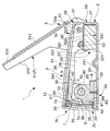
- the center sectional view of the binding tool. The disassembled perspective view which shows the tooth holder and main shaft of the binding tool.
- FIG. 12 is a sectional view taken along line BB in FIG. 11.
- FIG. 12 is a sectional view taken along the line CC of FIG. D partial enlarged view of FIG. Schematic which shows the preparation procedure of the tooth
- the disassembled perspective view of the binding tool The center sectional view of the binding tool.
- the binding tool 1 includes a plurality of sheets P1 stacked between a pair of teeth 6 and 7 that contact and separate in a fixed direction.
- a booklet P can be formed by binding the plurality of sheets P1 to each other by binding the sheets P1 with the sheet P1 sandwiched therebetween.
- the binding tool 1 has a pair of teeth 6 and 7 that make contact and separation in a certain direction, and inclined surface portions 62 and 72 that form predetermined inclination angles A1 and A2 with respect to the contact and separation direction, respectively.
- a part of the sheet P1 that is provided and is laminated with a plurality of sheets between the teeth 6 and 7 at the inclined surface portions 62 and 72 of the paired teeth 6 and 7 is pressed while the sheet material is stretched. Thus, it is possible to bind these sheets P1.
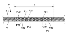
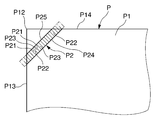
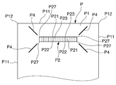
- the booklet P is formed by bundling a plurality of sheets P1, and these sheets P1 are joined to each other at one press portion P2 set on the edge P11. Yes.
- One sheet P1 used in this embodiment has 64 grams / m @ 2 and a thickness dimension of 0.1.
- the copy paper P1 is 08 to 0.09 mm, other paper P1 may be used as long as the following effects can be obtained. For example, drawing paper, slip, receipt paper, inkjet printer paper, glossy paper, recycled paper, etc. Various paper materials such as paper copy paper can be used.
- the sheets P1 to be bound are preferably of the same quality, but different sheets P1 can be bound together. In the binding tool 1 in this embodiment, it is possible to bind about 2 to 5 copy sheets P1 described above.
- the press portion P2 has a rectangular shape in plan view, so that the width dimension L7 is less than 0.6 to 4.0 mm and the length dimension L8 is less than 8 to 20 mm. It is good to set to. In particular, when used as an office binding tool 1, it is preferable to set the width dimension L7 to be about 1.4 mm and the length dimension L8 to be about 10 mm.
- the sheet P can be held at P2. That is, when the width dimension L7 and the length dimension L8 are within this range, the relationship between the exclusive area of the press part P2, the force necessary for the operation, and the holding force necessary for binding the paper P1. The balance is particularly good. The reason why the length L8 is preferably 8 to less than 20 mm will be described later.
- the press part P2 has a cross-sectional waveform shape, and in this embodiment, it is set to 10 peaks.
- the number of ridges of the press part P2 is not limited to 10 ridges and can be variously changed. However, if the number of peaks in the press portion P2 increases within a limited range, there is a problem that the inclination angles A1 and A2 of the peaks are too small and the paper P1 is easily torn. On the other hand, when the number of ridges is reduced within a limited range, the press portion P2 has an excessively large inclination angle A1 and A2, and the force is distributed over the area to be compressed, which is applied per unit area. The problem that a load will become small arises. That is, there is a problem in that it cannot be bound properly.
- the press part P2 is compression-molded by a mountain-shaped deformed part P21 formed by the mountain side curved surface part 61 of one tooth 6 and the valley side curved surface part 73 of the other tooth 7 and the inclined surface parts 62 and 72 of both teeth 6 and 7.
- the inclined compression portion P22 formed and a plurality of valley-shaped deformed portions P23 formed by the valley-side curved surface portion 63 of one tooth 6 and the mountain-side curved surface portion 71 of the other tooth 7 form a waveform in cross-sectional view.
- the press portion P2 is formed into a shape having such a cross-sectional waveform by extending each sheet material forming a plane by the strong pressure of the teeth 6 and 7.
- a line is attached to an intermediate point between the apex of the mountain-shaped deformation portion P21 and the valley bottom of the valley-shaped deformation portion P23.
- the “paper material” is a concept indicating all the materials constituting the paper P1, and includes paper, plastic fibers, and the like.
- the elongation rate of the paper material is preferably more than 1.32 and not more than 1.60. More preferably, the expansion rate of the paper material is 1.36 or more and 1.47 or less, and in this embodiment, the expansion rate of the paper material is set to 1.44.
- the sheets P1 are bound with a certain holding force by stretching and compressing the fibers of the sheet material based on the following principle. That is, it is considered that the adjacent sheets P1 are held so as not to be separated from each other by an anchor effect and a hydrogen bonding effect described later.
- the anchor effect means that the fibers of the paper material are stretched and exposed, and the fibers of the adjacent paper material are entangled in the compression direction, particularly in the portion sandwiched between the inclined surface portions 62 and 72, so On the other hand, it means a phenomenon accompanied by a great resistance to shear peeling in the direction inclined.
- the hydrogen bonding effect is due to the bonding between OH groups (hydroxyl groups) that are close to each other by the compressive force between the adjacent papers P1, more specifically, without the moisture due to the strong compressive force, the paper material of one paper P1. Based on a phenomenon in which OH groups contained in cellulose molecules constituting fibers are directly bonded to OH groups of cellulose molecules constituting fibers of paper material of other paper P1 located in the vicinity of the OH groups. The hydrogen bonding effect becomes more prominent as the force for compressing the sheets P1 increases.
- the elongation rate is 1.32 or less, a sufficient anchor effect cannot be obtained, and the hydrogen bonding effect is also reduced. Therefore, there arises a problem that the holding force of the paper P1 is not practical.
- the expansion ratio is larger than 1.60, there arises a problem that the paper P1 is torn or the energy required for the operation becomes excessive. That is, if the elongation rate is increased within a range where the paper P1 is not torn, more fibers can be exposed and the above-described anchor effect and hydrogen bonding effect can be easily developed. In other words, if the elongation ratio is 1.32 or less, a large anchor effect or hydrogen bonding effect cannot be expected within a practical operating force range.
- FIG. 1 The binding tool 1 used when binding the paper P1 in this way will be described with reference to FIGS. 1 to 3 and FIGS. 5 to 23.
- FIG. 1 The binding tool 1 used when binding the paper P1 in this way will be described with reference to FIGS. 1 to 3 and FIGS. 5 to 23.
- the binding tool 1 includes a plurality of stacked sheets P1 between teeth 6 and 7 that make a pair approaching and separating in a certain direction.
- a first receiving base 2 for urging the first teeth 6 in the pinching direction is capable of binding the paper P1 with both teeth 6 and 7 and binding the paper P1.
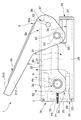
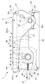
- the second receiving base 3 for urging the second teeth 7 in the clamping direction, the main shaft 4 pivotally attaching the receiving bases 2 and 3 at the tip vicinity portions 2a and 3a, and the first The urging mechanism 5 for applying a clamping force to the teeth 6 and 7 by pushing the base end portions 2b and 3b of the second receiving bases 2 and 3 to each other, and the main shaft 4 rotating.
- the binding tool 1 has a tooth tip 6b of the first tooth 6 and an axis 4a of the main shaft 4 along a virtual reference plane 11 on which the paper P1 to be bound is placed.
- the first receiving base 2 biases the first teeth 6 in the clamping direction at the tip vicinity portion 2a. belongs to.
- the first receiving base 2 includes a base main body 21 supported by the main shaft 4, and a hard tooth receiving member 22 that is held by the base main body 21 and presses the base end 6a of the corresponding tooth 6 in the clamping direction.
- a plate member 23 disposed between the tooth receiving member 22 and the base body 21 is provided.
- the base main body 21 includes a bottom plate 24, a pair of side walls 26 erected from both side edges of the bottom plate 24, and It comprises a front wall 25 that extends inward from the front ends of the side walls 26 and a rear wall 27 that extends upward from the rear end of the bottom plate 24, and bends the sheet metal material. By doing so, it is molded integrally.
- the bottom plate 24 is provided with a bent portion 241.
- a shaft hole 261 through which the main shaft 4 passes is provided in the vicinity of the front end of the side wall 26.
- the tooth receiving member 22 has a reaction force from the first teeth 6 at the time of clamping, as shown in FIG. 1, FIG. 2, FIG. It is intended to suppress intensive action at a specific location, and is made of a hard material such as spring steel.
- the plate member 23 is a plate-like member interposed between the tooth receiving member 22 and the base body 21 as shown in FIGS. 1, 2, 6, 8, 9, and 18 to 22. belongs to.
- the second receiving base 3 biases the second teeth 7 in the clamping direction in the vicinity of the tip 3a. belongs to.
- the second receiving base 3 includes a base main body 31 supported by the main shaft 4, and a hard tooth receiving member 32 that is held by the base main body 31 and presses the base end 7a of the corresponding tooth 7 in the clamping direction.
- a plate member 33 disposed between the tooth receiving member 32 and the base body 31 is provided.
- the base body 31 includes a top plate 34 and a pair of side walls 36 that are suspended from both side edges of the top plate 34. And a front wall 35 extending inward from the front ends of the side walls 36 and a rear wall 37 extending downward from the rear end of the top plate 34.
- the second receiving base 3 has a U-shaped cross section having side walls 36 on both sides, and the side wall 36 is provided on the operation handle 51 in a state where the operation handle 51 described later is not operated.
- the cut-out part 361 into which the pressed member 53 described later enters is provided.
- a shaft hole 362 through which the main shaft 4 passes is provided in the vicinity of the front end of the side wall 36.
- a shaft hole 363 through which a sub shaft 10 described later passes is provided in the vicinity of the rear end of the side wall 36.
- the top plate 34 is provided with a bulging portion 341 for reinforcement.
- the tooth receiving member 32 has a reaction force from the second tooth 7 during clamping so that the second receiving base 3 has a reaction force. It is intended to suppress intensive action at a specific location, and is made of a hard material such as spring steel.
- the plate member 33 is a plate-like member interposed between the tooth receiving member 32 and the base body 31 as shown in FIGS. 1, 2, 6, 8, 9, and 18 to 22. belongs to.
- the main shaft 4 includes the first and second receiving bases 2 and 3 in the vicinity of the distal ends 2a and 3a. It is something that pivots on.
- the main shaft 4 not only pivots the first receiving base 2 and the second receiving base 3, but also connects the first and second tooth holders 8 and 9 with the teeth 6 and 7. It also functions as a common shaft that supports the direction.
- the urging mechanism 5 pushes predetermined portions of the first and second receiving bases 2 and 3 apart from each other.
- the urging mechanism 5 includes an operation handle 51 provided on the second receiving base 3, an elastic repulsion member 52 provided on the first receiving base 2, and an outer peripheral surface 531 in contact with the elastic repulsion member 52. In this way, the predetermined portion of the first receiving base 2 is separated from the predetermined portion of the second receiving base 3 through the elastic repulsion member 52 as the operating handle 51 is provided. And a shaft-like pressing member 53 that presses against the shaft.
- the operation handle 51 has a U-shaped cross section having side walls 512 on both sides.
- the second receiving base 3 is configured to be fitted on the second receiving base 3 while being operated to the position (L). That is, both side walls 512 of the operation handle 51 are brought into contact with the outer surface of the side wall 36 of the second receiving base 3, and both side walls 512 at the base end portion of the operation handle 51 are connected to the second receiving base 3. Via the subshaft 10, it is pivotally attached to the both side walls 36 in the base end part 3b.
- the top plate 511 of the operation handle 51 is provided with a bulging portion 514 for reinforcement.
- a shaft hole 513 through which the sub shaft 10 passes is provided in the vicinity of the rear end of the side wall 512.
- a pressing member 53 is installed at a position eccentric from the shaft hole 513 of the both side walls 512.
- the pressing member 53 is attached to the operation handle 51 so that an outer peripheral surface 531 is in contact with the elastic repulsion member 52.
- the base end 2b of the first receiving base 2 is separated from the base end 3b of the second receiving base 3 through the elastic repulsion member 52 in accordance with the operation of the operation handle 51. It is a shaft that presses in the direction.
- the elastic repulsion member 52 includes a rubber member main body 521 having a rectangular parallelepiped shape, and an upper surface of the member main body 521.
- the member main body 521 is attached to the upper surface of the base end portion 2 b of the first receiving base 2.
- the rubber pressing plate 522 has a top plate portion 523 for distributing and transmitting the load from the pressing member 53 to the member main body 521, and a slip-preventing member that is suspended downward from the front edge and both side edges of the top plate portion 523.
- the restricting plate portion 524 is provided.
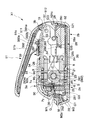
- the operation handle 51 can rotate between a standby position (F) shown in FIGS. 1, 8, and 18 to a final position (L) shown in FIGS. 2, 5, 6, 9, and 22.
- the elastic repulsion member 52 is compressed by a predetermined stroke by the pressing member 53 while reaching the final position (L) from the standby position (F).
- the stroke is set to about 3.8 mm.
- the urging mechanism 5 is connected to the base end portion 3b of the second receiving base 3 via the sub shaft 10 as shown in FIGS. 1, 2, 5 to 9, and 18 to 23.
- the operation handle 51 is attached to the shaft, and the pressing member 53 is fixed at a position eccentric from the sub-shaft 10 of the operation handle 51.
- the operation handle 51 is attached to the first and second receiving bases 2, 3.
- the pressing member 53 is configured to move toward the base ends 2d and 3d while being pressed against the elastic repulsion member 52 by being rotated toward the distal ends 2c and 3c.
- the urging mechanism 5 is configured such that the pressing member 53 is positioned closer to the first receiving base 2 than the virtual reference surface 11 in a state where the operation handle 51 is operated to the final position (L), and the sub shaft 10 is set to be located closer to the second receiving base 3 than the virtual reference plane 11.
- the binding tool 1 has a projection distance L5 with respect to the virtual reference plane 11 from the tooth tips 6b, 7b of the teeth 6, 7 to the axis 4a of the main shaft 4.
- the ratio of the projection distance L6 to the virtual reference plane 11 from the axis 4a of the main shaft 4 to the axis 10a of the sub-shaft 10 is 1: X, the X is 1 to 6.2. What is comprised is preferable.
- X is smaller than 1, it is necessary to unreasonably increase the lever ratio of the operation handle 51 under the condition that a practical number of sheets P1, for example, five sheets P1 are bound by manual operation. There is.
- the operation handle 51 becomes larger than the receiving bases 2 and 3, and the balance of the entire binding tool 1 is deteriorated or the entire binding tool 1 is increased in size.
- X becomes larger than 6.2, in order to bind a practical number of sheets P1, the size of each component including the receiving bases 2 and 3 is increased.
- the pinching pressure of the teeth 6 and 7 with respect to the operation force applied to the operation handle 51 is required 20 times or more. Therefore, in order to bind a practical number of sheets P1 without causing an increase in the size of the binding tool 1 or a loss of balance, it is desirable to satisfy the above conditions.
- the projection distance L5 with respect to the virtual reference plane 11 from the tooth tips 6b, 7b of the teeth 6, 7 to the axis 4a of the main shaft 4 is about 11.0 mm.
- the projection distance L6 from the axis 4a to the axis 10a of the sub-shaft 10 with respect to the virtual reference plane 11 is about 50.0 mm, and the X is set to 4.5. If set, the entire binding tool 1 can be designed with good balance.
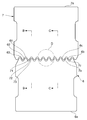
- the first tooth 6 includes a plurality of ridge-side curved surface portions 61 that form a ridge of the tooth 6, and the tooth 6.
- the crest-side curved surface portion 61, the trough-side curved surface portion 63, and the inclined surface portion 62 form a tooth surface 6c having a corrugated cross section.
- the first teeth 6 are made of a plate-shaped metal material that can be easily pressed with the width of the tooth surface 6c set to be less than 0.6 to 4.0 mm.
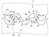
- the first tooth 6 is set such that the absolute value of the inclination angle A ⁇ b> 1 with respect to the contact / separation direction of the tooth 6 of the inclined surface portion 62 is less than 38 °. Yes.
- the absolute value of the inclination angle A1 with respect to the contact / separation direction of the teeth 6 of the inclined surface portion 62 is 25 ° or more and 38. What is less than ° is preferable. If the absolute value of the inclination angle A1 is less than 25 °, the angle of the first teeth 6 becomes steep and the paper P1 is easily torn. On the other hand, when the absolute value of the inclination angle A1 exceeds 38 °, the anchor effect and the hydrogen bonding effect described above cannot be sufficiently exhibited.
- the sheet P1 can be efficiently stretched and compressed without breaking the paper P1.
- the first tooth 6 has a half length L ⁇ b> 11 along the waveform of the mountain-side curved surface portion 61, and a length along the waveform of the inclined surface portion 62. It is more than L12.
- gear 6 has the same half L11 of the length along the said waveform of the said peak side curved surface part 61, and the length L12 along the said waveform of the said inclined surface part 62.
- half the length L11 along the waveform of the mountain side curved surface portion 61 is a concept indicating the length of the geodesic line from the apex of the mountain side curved surface portion 61 to the boundary with the inclined surface portion 62.
- the “length L12 of the inclined surface portion 62 along the waveform” is a concept indicating the shortest distance between the boundary with the mountain-side curved surface portion 61 and the boundary with the valley-side curved surface portion 63.
- the length L12 along the waveform is set to be approximately equal to the half L13 of the length along the waveform of the mountain-side curved surface portion 71 facing the valley-side curved surface portion 63. If the half L11 of the length along the waveform of the ridge-side curved surface portion 61 is set to be longer than the length L12 along the waveform of the inclined surface portion 62, the sheet material is stretched to cause deformation. It becomes easy. However, in order to prevent the paper P1 from being pulled excessively or to prevent a part of the paper P1 from being overloaded, the half L11 of the length along the waveform of the peak side curved surface portion 61 is: It is preferable to make it equal to the length L12 of the inclined surface portion 62 along the waveform.
- the “elongation rate” in this specification is defined as follows. That is, when the crest-side teeth 6 and the trough-side teeth 7 are engaged with each other, half the length L11 along the waveform of the crest-side curved surface portion 61 and length L12 along the waveform of the inclined surface portion 62
- the sum of the length dimension L13 along the waveform of the mountain side curved surface portion 71 facing the valley side curved surface portion 63 is Y
- the center point of the mountain side curved surface portion 61 and the valley side curved surface portion 63 are When the length dimension L14 obtained by projecting the line connecting the center point of the mountain-side curved surface portion 71 facing to the virtual reference plane 11 is Z, the expansion ratio is expressed by Y / Z.
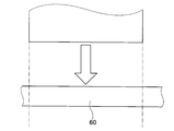
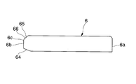
- the first tooth 6 is provided with the tooth surface 6c having a corrugated cross section having peaks and valleys as described above, and the tooth tip 6b. Is provided with an inclined guide portion 66 for guiding the paper P1 to the paper insertion gap 12. More specifically, the first tooth 6 is formed by stamping a metal material 60 by press working as schematically shown in FIGS. 16 and 17. Chamfered portions 64 and 65 are formed on both sides in the thickness direction. These chamfered portions 64 and 65 are formed by performing cutting or plastically deforming with a press die on both sides in the thickness direction of the metal material 60.
- the first tooth 6 has one chamfered portion 64 set larger than the other chamfered portion 65.
- the chamfering depth D2 of the chamfered portion 65 located on the front side of the tooth 6 is set to be shallower than the chamfered depth D1 of the chamfered portion 64 located on the back side of the tooth 6.
- An intermediate plane portion of the chamfered portion 65 on the side is the inclined guide portion 66.
- the chamfering depth D2 of the chamfered portion 65 on the front side is set substantially equal to the depth D3 of the troughs of the teeth 6, and the inclined guide portion 66 is more than the troughs of the respective teeth 6. It is located on the tooth tip 6b side.
- “Deep depth D3 of tooth 6” is a concept indicating the shortest distance from the surface connecting the peaks of adjacent teeth 6 to the valley of teeth 6.
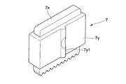
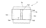
- the second tooth 7 includes a plurality of ridge-side curved surface portions 71 that form a ridge of the tooth 7.
- the plurality of valley-side curved surface portions 73 that form the valleys of the teeth 7, and the plurality of the above-described plurality of the valley-side curved surface portions 71 that are continuously formed between the end portions 711 of the mountain-side curved surface portions 71 and the end portions 731 of the valley-side curved surface portions 73.
- An inclined surface portion 72 is provided, and the crest-side curved surface portion 71, the valley-side curved surface portion 73, and the inclined surface portion 72 form a tooth surface 7c having a corrugated cross section.
- the second teeth 7 are made of a plate-like metal material that can be easily pressed with the width of the tooth surface 7c set to be less than 0.6 to 4.0 mm.
- the second tooth 7 is set such that the absolute value of the inclination angle A ⁇ b> 2 with respect to the contact / separation direction of the tooth 7 of the inclined surface portion 72 is less than 38 °.
- the absolute value of the inclination angle A2 with respect to the contact / separation direction of the teeth 7 of the inclined surface portion 72 is preferably 25 ° or more and less than 38 °.
- the absolute value of the inclination angle A2 is less than 25 °, the angle of the first teeth 6 becomes steep and the paper P1 is easily torn.
- the absolute value of the inclination angle A2 exceeds 38 °, the anchor effect and the hydrogen bonding effect described above cannot be sufficiently exhibited.
- the sheet P1 can be efficiently stretched and compressed without breaking the paper P1.
- the second tooth 7 has a half length L ⁇ b> 21 along the waveform of the mountain-side curved surface portion 71, and a length along the waveform of the inclined surface portion 72. It is more than L22.
- the second tooth 7 is preferably such that the half L21 of the ridge-side curved surface portion 71 along the waveform and the length L22 of the inclined surface portion 72 along the waveform are equal.
- the “length L22 along the waveform of the mountain-side curved surface portion 71” is a concept indicating the length of the geodesic line from the apex of the mountain-side curved surface portion 71 to the boundary with the inclined surface portion 72.
- the “length L22 of the inclined surface portion 72 along the waveform” is a concept indicating the shortest distance between the boundary with the mountain-side curved surface portion 71 and the boundary with the valley-side curved surface portion 73.
- the second tooth 7 meshes the mountain side tooth 7 and the valley side tooth 6, the half L 21 of the length along the waveform of the mountain side curved surface portion 71 and the inclined surface portion 72.
- the length L22 along the waveform and the half L23 of the length along the waveform of the mountain-side curved surface portion 61 facing the valley-side curved surface portion 73 are set to be approximately equal.
- the half L21 of the length along the waveform of the ridge-side curved surface portion 71 is set to be equal to or longer than the length L22 along the waveform of the inclined surface portion 72, the paper material is stretched to cause deformation. It becomes easy.
- the half L21 of the ridge-side curved surface portion 71 along the waveform is: It is preferable to make it equal to the length L22 of the inclined surface portion 72 along the waveform.
- the “elongation rate” in this specification is defined as follows. That is, when the crest-side teeth 7 and the trough-side teeth 6 are engaged with each other, half the length L21 along the waveform of the crest-side curved surface portion 71, and length L22 along the waveform of the inclined surface portion 72, The sum of the length dimension L23 along the waveform of the mountain side curved surface portion 61 facing the valley side curved surface portion 73 is Y, and the center point of the mountain side curved surface portion 71 and the valley side curved surface portion 73 are defined as Y.
- the length dimension L24 obtained by projecting the line connecting the center point of the mountain-side curved surface portion 61 facing to the virtual reference plane 11 is Z
- the expansion ratio is expressed as Y / Z.
- the second tooth 7 includes a tooth surface 7c having a corrugated cross section having a crest and a trough as described above,
- An inclined guide portion 76 for guiding the paper P1 to the paper insertion gap 12 is provided at the front edge of the tooth tip 7b.
- the second tooth 7 is made by stamping a metal material (not shown) by pressing, and chamfered portions 74 and 75 are formed on both sides of the metal material in the tooth tip 7b in the thickness direction. Yes.
- chamfered portions 74 and 75 are formed by cutting or plastically deforming with a press die.
- one chamfered portion 74 is set larger than the other chamfered portion 75.
- the chamfering depth D5 of the chamfered portion 75 located on the front surface side of the tooth 7 is set to be shallower than the chamfered depth D4 of the chamfered portion 74 located on the back surface side of the tooth 7.
- An intermediate plane portion of the side chamfered portion 75 serves as the inclined guide portion 76.
- the chamfering depth D5 of the chamfered portion 75 on the front side is set to be substantially equal to the depth D6 of the troughs of the teeth 6 and 7, and the inclined guide portion 76 It is located on the tooth tip 7b side.
- “Deep depth D6 of tooth 7” is a concept indicating the shortest distance from the surface connecting the peaks of teeth 7 adjacent to each other to the valley of teeth 7.
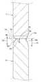
- the first teeth 6 and the second teeth 7 are the distances between the inclined surface portions 62 and 72 of the pair of teeth 6 and 7, that is, the inclined surface portions 62 and 72 are connected to each other.
- the length of the normal line corresponding to the shortest distance L3 is close to 0.09 mm
- the length of the portion where the inclined surface portions 62 and 72 face each other that is, the main portion by the two inclined surface portions 62 and 72.
- the length L4 in the direction perpendicular to the normal line of the pressure contact region is set to be less than 0.18 mm.
- the two inclined surface portions in a state where the normal L corresponding to the shortest distance between the inclined surface portions 62 and 72 of the pair of teeth 6 and 7 is close to 0.09 mm.
- the length L4 in the direction perpendicular to the normal line of the main pressure contact region 62, 72 is preferably more than 0 mm and less than 0.18 mm. If the length L4 of the portion where the inclined surface portions 62 and 72 face each other is 0.18 mm or more, the force is dispersed over a wide area to be compressed, so that it is difficult to increase the holding force. That is, if the length L4 in the direction perpendicular to the normal line of the main pressure contact region by the inclined surface portions 62 and 72 is greater than 0 mm and less than 0.18 mm, the compression area is appropriate. It is possible to concentrate the force efficiently only on the portion where the fibers of the adjacent paper P1 are entangled with each other. Therefore, a strong binding force can be obtained with a force within a practical range.
- the first tooth holder 8 and the second tooth holder 9 are in sliding contact with each other as shown in FIGS. 1, 2, 6 to 10, and 18 to 22, respectively. , 9 are provided with positioning surfaces 86 and 96 for positioning in the direction of the shaft 4 axis 4a.
- the first tooth holder 8 is integrally formed of synthetic resin, and a holder body 81 that holds the teeth 6 is used. And a bearing portion 82 that rotatably supports the holder body 81 on the shaft 4.
- the first tooth holder 8 includes a single bearing portion 82 having positioning surfaces 86 on both sides.
- the first tooth holder 8 is held by the first receiving base 2. That is, the first tooth holder 8 is fixed to the upper surface of the plate member 23 of the first receiving base 2 using screws 85.
- the first tooth holder 8 receives the paper P1 inserted in the paper insertion gap 12 formed between the upper surface side of the first tooth holder 8 and the lower surface side of the second tooth holder 9.
- a locking wall 83 is provided at the part in contact, that is, at the back of the gap.
- the first tooth holder 8 has a plan view of the locking wall 83 for positioning the paper P1 by bringing the corner P12 of the paper P1 into contact with the central portion of the locking wall 83. It has a positioning portion 84 formed by cutting out a right isosceles triangle.
- the second tooth holder 9 is integrally formed of synthetic resin, and a holder body 91 for holding the teeth 7 is used. And a bearing portion 92 that rotatably supports the holder body 91 on the shaft 4.
- the second tooth holder 9 includes a pair of bearing portions 92 each having a positioning surface 96 on the opposite surface, and the second tooth holder 9 is provided on both sides of the bearing portion 92 of the first tooth holder 8.
- a pair of bearing portions 92 are arranged, and the positioning surfaces 96 of the respective bearing portions 92 are in sliding contact with each other.
- the second tooth holder 9 is not held by the second receiving base 3. That is, a gap 13 that gradually expands forward is formed between the upper surface of the second tooth holder 9 and the lower surface of the plate member 33 of the second receiving base 3.
- the first receiving base is acted on by the action of a return spring (not shown) provided between the first receiving base 2 and the second receiving base 3. 2 and the base end portions 2b and 3b of the second receiving base 3 are in the closest state.
- the pressing member 53 is in contact with the upper surface of the elastic repulsion member 52 in a state in which the operation handle 51 jumps upward. In this state, the tooth tips 6b and 7b of the first tooth 6 and the second tooth 7 are held apart from each other.
- the plurality of stacked sheets P1 are inserted into the sheet insertion gap 12 formed between the first teeth 6 and the second teeth 7, and the locking is performed. Positioning is performed at a position in contact with the wall 83.
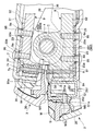
- the pressing member 53 presses downward while moving the upper surface of the elastic repulsion member 52 backward, and the second teeth 7. Is strongly urged in the direction of the first teeth 6 and the paper P1 is pinched. From the stage in which the paper P1 is compressed to the limit, and in the stage in which the operation handle 51 is further rotated to the final position (L) as shown in FIG. 22, the pressing member 53 exclusively elastically repels the elastic repulsion member 52. It moves downward while deforming. Therefore, the operation handle 51 is allowed to rotate while gradually increasing the clamping force of the teeth 6 and 7 with respect to the paper P1.
- the paper P1 that has received such a pinching pressure is compressed and deformed into a cross-sectional waveform while the paper material is stretched. At that time, in the region where the inclined surface portion 62 of the first tooth 6 and the inclined surface portion 72 of the second tooth 7 face each other, the strongest compressive force is applied to the paper P1, mainly in this portion.
- the anchor effect and the hydrogen bonding effect described above are exhibited, and a plurality of sheets P1 are bound to each other.
- “holding force” is a constant value at one end in the longitudinal direction of recycled paper copy paper P1 corresponding to the A4 size, for example, when the clamping force by the both teeth 6 and 7 using the binding tool 1 is around 150 kg. This is an index indicating the ease of peeling when the other end side of the copy paper P1 is turned up.
- the holding force is “impossible”, it means that the press part P2 is easily peeled off when it is turned up and is not practically used.
- a holding force of “possible” means a state where the press part P2 is not easily peeled off when turned up.
- the holding power is “good”, it means that the press portion P2 is firmly bound when turned up and can be sufficiently put into practical use. The results are shown below. Note that since the holding force varies depending on the quality of the sheets to be bound, the temperature and humidity of the space where the sheets are bound, specific numerical values of the holding forces are not shown.
- Example 1 the result that the holding power was “good” was obtained in both cases of binding 2 sheets and 4 sheets.
- Example 2 the holding force when binding two sheets was “good”, and the holding force when binding four sheets was “possible”.
- Example 3 the retention strength was slightly inferior in the case of 4 sheets, but the retention strength was “good” in the case of 2 sheets.
- the absolute values of the inclination angles A1 and A2 described above, the length L4 in the direction perpendicular to the normal line of the main pressure contact area formed by the inclined surface portions 62 and 72, and the elongation rate of the paper material are: Although they can independently affect the anchor effect and / or the hydrogen bonding effect, it is considered that they are not linked to each other.
- reference examples 1, 2, 3, 4, and 5 relating to the length dimension L8 of the press portion P2 described above will be described with reference to FIG.
- the shape of the teeth for one pitch (one crest) is the same as that of the first embodiment described above, and the length dimension L8 is changed by changing the number of crests.
- These are set to 5 mm, 8 mm, 10 mm, 15 mm, and 20 mm.
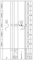
- FIG. 25 shows the result of the same experiment as the retention force experiment performed on Examples 1 to 3 and the comparative example using the teeth of Reference Examples 1 to 5. ”,“ OK ”, and“ Good ”are the same as described above.
- the length dimension L8 of the press part P2 (and the longitudinal dimension of the teeth 6 and 7 corresponding thereto) is preferably 8 mm to 15 mm. That is, when the length L8 of the press portion P2 is smaller than 8 mm, the total area of the inclined surfaces 62 and 72 facing each other in the teeth 6 and 7 as a whole is small, and the paper viewed from the press portion P2 as a whole. Since there are too few places where P1 is compressed, the hydrogen bonding effect cannot be exhibited sufficiently. On the other hand, when the length L8 of the press part P2 is 20 mm or more, the load per unit area is reduced by increasing the total area of the inclined surfaces 62 and 72 facing each other in the teeth 6 and 7 as a whole. End up. This is considered to be due to the fact that the force applied to the teeth 6 and 7 is not concentrated and the hydrogen bonding effect is hardly exhibited.
- the binding tool 1 of this embodiment is provided with inclined surface portions 62 and 72 that form predetermined inclination angles A1 and A2 with respect to the contact and separation directions on the pair of teeth 6 and 7 that contact and separate in a certain direction, respectively.
- the sheet P1 can be bound, and the absolute values of the inclination angles A1 and A2 with respect to the contact and separation directions of the teeth 6 and 7 of the inclined surface portions 62 and 72 are less than 38 °, and the teeth forming the pair 6 and 7 in the main pressure contact region formed by the two inclined surface portions 62 and 72 in a state in which the normal length L3 corresponding to the shortest distance between the inclined surface portions 62 and 72 is 0.09 mm.
- the length L4 in the direction perpendicular to the line is 0.18 mm.
- elongation of the sheet material is greater than 1.32 to 1.60.
- the elongation rate The sheet P1 can be bound with a relatively small operating force while maintaining the state of exceeding 1.32 and not exceeding 1.60, and a practical holding force can be maintained in the bound state.
- each of the teeth 6 and 7 includes a plurality of crest-side curved surface portions 61 and 71 forming crests of the teeth 6 and 7, a plurality of trough-side curved surface portions 63 and 73 forming troughs of the teeth 6 and 7, and A plurality of the inclined surface portions 62 and 72 formed continuously between the end portions 611 and 711 of the mountain-side curved surface portions 61 and 71 and the end portions 631 and 731 of the valley-side curved surface portions 63 and 73, respectively.
- the tooth surface 6c, 7c is relatively simple because the mountain side curved surface portions 61, 71, the valley side curved surface portions 63, 73 and the inclined surface portions 62, 72 form the tooth surfaces 6c, 7c having a corrugated cross section. Can be formed. Further, since the press part P2 formed by these teeth 6 and 7 has directionality, it can resist turning of the paper P1 in a direction orthogonal to the longitudinal direction of the press part P2 with a relatively strong force. it can.
- the absolute values of the inclination angles A1 and A2 with respect to the contact and separation direction of the teeth 6 and 7 of the inclined surface portions 62 and 72 are 25 ° or more and less than 38 °.
- A1 and A2 are too small, that is, the inclination of the teeth 6 and 7 is too steep, the portion pressed by the inclined surface parts 62 and 72 of the press part P2, that is, the inclined compression part P22 can be prevented from being broken.
- the angle is made steep, the teeth 6 and 7 bite into the paper P1 deeper, so that the problem that the paper P1 cannot withstand the force received from the teeth 6 and 7 is broken.
- the inclination angles A1 and A2 of the teeth 6 and 7 are too large, that is, when the inclination of the teeth 6 and 7 is too gentle, the area where the paper P1 is compressed becomes large and the force is dispersed. Can be suppressed. Therefore, the anchor effect and the hydrogen bonding effect can be effectively exhibited.
- the two inclined surface portions 62, 72 are brought close to each other so that a normal length L3 corresponding to the shortest distance between the inclined surface portions 62, 72 of the paired teeth 6, 7 is 0.09 mm. Since the length L4 in the direction perpendicular to the normal line of the main pressure contact area is more than 0 mm and less than 0.18 mm, the force can be concentrated on a relatively small area, and the hydrogen bonding effect can be sufficiently exhibited. be able to.
- the expansion rate of the paper material is 1.36 or more and 1.47 or less, the expansion rate is too small while suppressing the paper P1 from being torn due to the expansion rate being too large. Accordingly, the problem that it is difficult to sufficiently exert the hydrogen bonding effect without increasing the surface area of the paper material to be compressed can be solved.
- the mountain side curved surface portion 61 is obtained.
- 71 can cause the sheet P1 to be deformed to a greater extent by compression than when the half lengths L11, L21 along the waveform of 71, are smaller than the lengths L12, L22 along the waveform of the inclined surfaces 62, 72. it can.
- the teeth 6 and 7 of the present embodiment are half lengths L11 and L21 along the corrugations of the mountain-side curved surface portions 61 and 71 and lengths L12 and L22 along the corrugations of the inclined surface portions 62 and 72, respectively. Therefore, it is possible to prevent the paper P1 from being pulled excessively and a part of the paper P1 from being loaded.
- a plurality of stacked sheets P1 are arranged between a pair of teeth 6 and 7 that contact and separate in a certain direction, and the sheet P1 is sandwiched between the teeth 6 and 7.
- the sheet P1 can be bound by pressing, and the first receiving base 2 for urging the first teeth 6 in the clamping direction and the second teeth 7 in the clamping direction.
- the second receiving base 3 for biasing, and the biasing force for applying a clamping pressure to the teeth 6 and 7 by expanding the predetermined portions of the first and second receiving bases 2 and 3 to each other.
- the mechanism 5 includes an operation handle 51 provided on the second receiving base 3, an elastic repelling member 52 provided on the first receiving base 2, and the elastic repelling member 52.
- the operation handle 51 is provided so that the outer peripheral surface 531 is in contact with the front surface of the operation handle 51.
- the structure of the binding tool is not limited to the combination with other components of the present embodiment, and can constitute a separate independent invention.
- the conventional one has a problem that the operation force applied to the operation handle becomes excessive in order to compress the paper so as to exhibit a holding force of a certain level or more.
- the operation handle when the operation handle is operated within the range of practical operation force, there is a problem that the holding force between the sheets is not practical.
- Such a problem is not limited to the manual operation of the operation handle, and an actuator having a large capacity is required even when the operation handle is operated electrically.
- the shaft-like pressing member 53 is not limited to the non-rotatable attachment to the operation handle 51 as in the present embodiment, but may be attached to the operation handle 51 to be rotatable. .
- the binding tool 1 includes a plurality of stacked sheets P1 disposed between a pair of teeth 6 and 7 that contact and separate in a certain direction, and the sheets P1 are disposed by the teeth 6 and 7.
- the sheet P1 can be bound by being pinched and includes a first receiving base 2 for urging the first teeth 6 in the pinching direction at the tip, and a second at the tip.
- a second receiving base 3 for urging the teeth 7 in the clamping direction
- a main shaft 4 that pivotally attaches both the receiving bases 2 and 3 at the tip vicinity portions 2a and 3a, and the first and second And an urging mechanism 5 for applying a clamping force to the teeth 6 and 7 by pushing the base end portions 2b and 3b of the receiving base 3 to each other.
- the urging mechanism 5 is a second receiving member.
- An operation handle 51 provided on the base 3, an elastic repulsion member 52 provided on the first receiving base 2, and the elastic repulsion member 52 The base end portion 2b of the first receiving base 2 is provided to the second receiving base via the elastic repulsion member 52 as the peripheral surface 531 comes into contact with the operating handle 51. 3 and a shaft-shaped pressing member 53 that presses in a direction away from the base end portion 3b. Therefore, the outer peripheral surface 531 of the pressing member 53 can be smoothly moved on the elastic repulsion member 52, and the energy required for the operation can be kept low.
- the structure of the binding tool is not limited to the combination with other components of the present embodiment, and can constitute a separate independent invention.
- the urging mechanism 5 pivotally attaches the operation handle 51 to the base end portion 3b of the second receiving base 3 via the sub shaft 10, and the operation handle 51 is located at a position eccentric from the sub shaft 10.
- the pressing member 53 is fixed, and the pressing member 53 is pressed against the elastic repulsion member 52 by rotating the operation handle 51 toward the distal ends 2c and 3c of the first and second receiving bases 2 and 3.
- the operation handle 51 and the receiving bases 2 and 3 are unbalanced in size so that a practical number of sheets P1 can be bound. Therefore, the problem that the balance of the binding tool 1 as a whole becomes worse or the binding tool 1 as a whole increases in size can be solved.
- the sub-shaft 10 is set to be located closer to the second receiving base 3 than the virtual reference plane 11. That is, since the pressing member 53 and the sub shaft 10 can be arranged across the virtual reference plane 11, the binding tool 1 as a whole can be made compact.
- the virtual reference surface 11 may be any surface as long as the sheet P1 to be bound is disposed, and the tooth tips of the teeth and the axis of the main shaft are not disposed on this surface. It may be a thing.
- the tooth tip 6b of the first tooth 6 and the axis 4a of the main shaft 4 are disposed along the virtual reference plane 11 on which the paper P1 to be bound is disposed.
- the pressing member 53 is positioned closer to the first receiving base 2 than the virtual reference plane 11 in a state where the urging mechanism 5 has operated the operation handle 51 to the final position (L). Since the sub-shaft 10 is set so as to be positioned closer to the second receiving base 3 than the virtual reference plane 11, the entire binding tool 1 can be made compact.
- the entire binding tool 1 can be kept in an appropriate balance. That is, in the binding tool 1 of the present embodiment, when X exceeds 6.2, it is impossible to insert five sheets of paper P1 between the upper and lower teeth 6 and 7 even if the handle is pulled up to the limit.
- the distance between the main shaft 4 and the sub shaft 10, the angle formed by the shafts 4, 10, the thickness dimension of the elastic repulsion member 52, and the like are not limited thereto.
- X is less than 1
- the binding tool 1 of the present embodiment has X set to about 4.5, and if X is smaller than this, the receiving bases 2, 3 and other parts become too large with respect to the operation handle 51. If X is larger than this, the operation handle 51 becomes too large with respect to the receiving bases 2 and 3. Therefore, if X is set to about 4.5 as in this embodiment, the usability can be improved as the binding tool 1 operated manually, and the size balance of the binding tool 1 as a whole can be optimized. Can do.
- the operation handle 51 has a U-shaped cross section having side walls 512 on both sides, and is externally fitted to the second receiving base 3 in a state where the operation handle 51 is operated to the final position (L). Since it is comprised, it can be made compact in the state which operated the operation handle 51 to the last position (L).
- the second receiving base 3 has a U-shaped cross section having side walls 36 on both sides, and the side wall 36 is provided on the operation handle 51 in a state where the operation handle 51 is not operated. Since the notched portion 361 into which the pressing member 53 enters is provided, the sub shaft 10, the pressing member 53, and the main shaft 4 can be disposed close to the virtual reference plane 11. Therefore, the binding tool 1 as a whole can be made compact.
- the teeth 6 and 7 of the binding tool 1 of the present embodiment are arranged with a plurality of stacked sheets P1 between the teeth 6 and 7 that make a pair approaching and separating in a certain direction.
- the tooth surface 6c, 7c is used in the binding tool 1 capable of pinching the paper P1 and binding the paper P1, and the teeth 6b, 7b have ridges and valleys in cross section.
- inclined guide portions 66 and 76 for guiding the paper P1 to the paper insertion gap 12 at the front edge of the tooth tips 6b and 7b.
- the inclined guide portions 66 and 76 are tooth tips than the valleys. Located on the 6b, 7b side.
- the tooth structure is not limited to a combination with other components of the present embodiment, and can constitute a separate independent invention.
- the conventional one is provided with chamfered portions on both sides in the thickness direction of the metal material at the tip of each tooth, and the chamfering depth of each chamfered portion is set larger than the depth of the valley of each tooth. It was.
- the trough portion having a curved shape may be exposed to the chamfered portion. obtain.
- the surface on the side where the sheet is inserted that is, the valley portion exposed on the chamfered portion located on the front side.
- the edge of the paper is caught.
- the paper P1 can be prevented from being caught on the teeth 6 and 7 as much as possible when the paper P1 is inserted.
- the teeth 6 and 7 having such inclined guide portions 66 and 76 may be formed by cutting or may be formed by pressing. As a specific example of cutting, manual work or machining can be considered.
- the inclined guide portions 66 and 76 are set on the tooth tips 6b and 7b side of the valley, the inclination of the chamfered portions 65 and 75 on the paper insertion side is so gentle that the paper P1 is not torn. It is possible to suppress breakage of the boundary portion P24 between the longitudinal end portion on the opposite end side of the paper P1 and the unpressed portion in the press portion P2 after the paper P1 is compressed. More specifically, the boundary portion P24 formed by the front side of the binding tool 1 (front edge portions of the tooth tips 6b and 7b) is located on the main body side of the bound booklet P. When the press part P2 is set at the end of the paper P1, the user often turns from the main body side of the booklet P when turning the paper P1.
- the teeth 6 and 7 are made by stamping a metal material 60, and chamfered portions 64, 65, 74, and 75 are provided on both sides of the tooth material 6b and 7b in the thickness direction of the metal material 60. Since the one chamfered portion 65, 75 is part of the inclined guide portions 66, 76 provided by pressing, each tooth 6, 7 can be easily formed by pressing.
- the inclined guide portions 66 and 76 can also be easily formed by press working. That is, the teeth 6 and 7 can be formed with relatively low cost by performing the flow operation in the progressive feeding only by press working.
- one of the chamfered portions 64 and 74 is set to be larger than the other chamfered portions 65 and 75, the size of the tooth surfaces 6c and 7c for compressing the paper P1 is secured, and the size of the paper P1. Breaking can be suppressed.
- each of the teeth 6 and 7 includes a plurality of sheets P1 stacked between a pair of teeth 6 and 7 that contact and separate in a certain direction.
- Chamfered portions 64, 65, 74, 75 are provided on both sides in the thickness direction by pressing.
- the tooth structure is not limited to a combination with other components of the present embodiment, and can constitute a separate independent invention.
- each tooth is made by subjecting a metal material to a relatively troublesome polishing process, and a large number of teeth formed by cutting such as manual work or machining. It was not suitable for production. However, if it is like this embodiment, a punching process and a chamfering process will be possible only by a press, and the teeth 6 and 7 for the binding tool 1 can be formed relatively easily while suppressing the production cost.
- the tooth surfaces 6c and 7c of the teeth 6 and 7 are not limited to corrugated shapes and can be changed variously. Furthermore, the valleys of the teeth 6 and 7 are of the same height as the lower end of the chamfered portion.
- the tooth tip side may be located on the tooth tip side with respect to the lower end portion of the chamfered portion, or may be located on the proximal side of the tooth with respect to the lower end portion of the chamfered portion.
- the size of one chamfered portion and the size of the other chamfered portion may be different from each other.
- a specific example is a tooth formed only by pressing, in which one chamfered portion and the other chamfered portion are set to different sizes, and a trough of teeth is formed on both chamfered portions. What is located in the tooth
- each of the teeth 6 and 7 includes a plurality of sheets P1 stacked between a pair of teeth 6 and 7 that contact and separate in a certain direction.
- the inclination is set to be gentler than the inclination of the chamfered portions 64 and 74 on the opposite side.
- “inclination” means an angle with respect to a virtual reference plane on which a sheet to be bound is arranged.
- the tooth structure is not limited to a combination with other components of the present embodiment, and can constitute a separate independent invention.
- the teeth in which the inclination of the chamfered portion on the paper insertion side is set more gently than the inclined surface of the opposite chamfered portion may be formed by cutting the chamfered portion, It may be formed by press working. As a specific example of cutting, manual work or machining can be considered.
- the lower end of the chamfered portion is located closer to the tip of the tooth than the trough of the tooth, is located at the same height as the trough of the tooth, is located proximal to the trough of the tooth Anything may be used.
- the chamfered portions 65 and 75 on the paper insertion side are configured to have a gentle slope.
- the chamfered portions 65 and 75 are not inclined gently. You can also
- a plurality of sheets of paper P1 are arranged between a pair of teeth 6 and 7 that contact and separate in a certain direction, and the paper P1 is sandwiched between the teeth 6 and 7.
- the sheet P1 can be bound by pressing, and the first receiving base 2 for urging the first teeth 6 in the clamping direction and the second teeth 7 in the clamping direction.
- a second receiving base 3 for urging, a first tooth holder 8 holding the first teeth 6, a second tooth holder 9 holding the second teeth 7, and the first and second And positioning means for positioning the two tooth holders 8 and 9 so as to perform a certain relative movement.
- the structure of the binding tool is not limited to the combination with other components of the present embodiment, and can constitute a separate independent invention.
- the positioning means can be variously changed such that the first and second tooth holders are completely connected and the first and second tooth holders are fitted and positioned.
- the positioning means is used to make the first and second tooth holders 8 and 9 independent of the operation handle 51 and the second receiving base 3 to which the operation handle 51 is attached.
- the first tooth holder for holding the first teeth is fixed to the first receiving base
- the second tooth holder for holding the second teeth is fixed to the second receiving base.
- the operation handle is pivotally attached to the second receiving base. Therefore, it is necessary to set the position of the tooth holder with respect to the receiving base very accurately so that the first tooth and the second tooth mesh at an appropriate position when the operation handle is rotated. In other words, there is a problem that the desired clamping pressure cannot be exerted if the position of the teeth is slightly shifted due to the error in the size of the parts or the shift of the mounting position of the tooth holder to the receiving base. there were.
- the first and second receiving bases 2 and 3 and the tooth holders 8 and 9 are positioned separately, so regardless of the accuracy of the receiving bases 2 and 3.
- the accuracy between the teeth 6 and 7 can be improved. Therefore, it is possible to provide the binding tool 1 that can secure the holding force of the bound paper P1 above a certain level.
- a sheet metal material as described above can be applied as the receiving bases 2 and 3.
- the positioning means only needs to support at least the first and second tooth holders 9, and is limited to the main shaft 4 pivotally attached to the first and second receiving bases 2 and 3. I can't.
- the first and second tooth holders 8 and 9 are set so as to be independent from the second receiving base 3. It may be independent of the receiving base 2 or may be independent of the receiving bases 2 and 3.
- the fixed relative motion between the first and second tooth holders 8 and 9 is not limited to the rotation motion, and can be variously changed such as a linear motion.
- the first teeth 6 and the second teeth 7 have a shape extending in a certain direction, and the positioning means is a short direction for relative positioning of the teeth 6 and 7 in the short direction. Since the positioning element and the longitudinal positioning element for performing relative positioning in the longitudinal direction of the teeth 6 and 7 are provided, the positions of the teeth 6 and 7 with respect to the paper P1 should be appropriate. Can do.
- the short-direction positioning element is the common shaft 4 that supports the first and second tooth holders 8 and 9 in the contact and separation direction of the teeth 6 and 7, the rotation operation of the tooth holders 8 and 9 is performed.
- the short dimension direction positioning element is the main shaft 4 that pivotally connects the first receiving base 2 and the second receiving base 3, the tooth holders 8, 9 with respect to the receiving bases 2, 3 are arranged in the front-rear direction. Misalignment can be suppressed.
- the longitudinal positioning elements are provided on the first tooth holder 8 and the second tooth holder 9 and are in sliding contact with each other to position the teeth 6, 7 of the tooth holders 8, 9 in the longitudinal direction. Therefore, it is possible to prevent the positional deviation between the tooth holders 8 and 9 in the left-right direction.
- the tooth holders 8 and 9 have holder main bodies 81 and 91 for holding the teeth 6 and 7, and bearing parts 82 and 92 for rotatably supporting the holder main bodies 81 and 91 on the short dimension positioning element. Since it is provided, it is supported by the common shaft 4 which is a short direction positioning element that penetrates the bearing portions 82 and 92 while appropriately holding the teeth 6 and 7 by the holder main bodies 81 and 91. Thus, the positions of the teeth 6 and 7 can be made appropriate.
- the first tooth holder 8 includes a single bearing portion 82 having positioning surfaces 86 on both sides, and the second tooth holder 9 is positioned on the opposing surface.
- a pair of bearing portions 92 having a face 96 is provided, and bearing portions 92 that form a pair of second tooth holders 9 are arranged on both sides of the bearing portion 82 of the first tooth holder 8, Since the positioning surfaces 86 and 96 of the bearing portions 82 and 92 are in sliding contact with each other, positioning in the left-right direction can be performed with a simple structure, and assembly work is easy to perform.
- first tooth holder 8 and the second tooth holder 9 are each integrally molded, the positional relationship between the bearing portions 82 and 92 and the tooth holders 8 and 9 can be determined firmly. The accuracy between the teeth 6 and 7 is easy to obtain.
- first tooth holder 8 and the second tooth holder 9 are each integrally formed of synthetic resin, the above accuracy is achieved despite the relatively complicated shape. Can be kept constant.
- first tooth holder 8 is held by the first receiving base 2 and the second tooth holder 9 is not held by the second receiving base 3, When an operation force is applied to the operation handle 51, an excessive force is not applied to the positioning surfaces 86 and 96.
- a plurality of stacked sheets P1 are arranged between a pair of teeth 6 and 7 that contact and separate in a certain direction, and the sheet P1 is sandwiched between the teeth 6 and 7.
- the sheet P1 can be bound by pressing, and the first receiving base 2 for urging the first teeth 6 in the clamping direction and the second teeth 7 in the clamping direction.
- the urging mechanism 5 for applying a clamping pressure to the teeth 6 and 7 by pushing the 2b and 3b apart from each other, and the first tooth 6 supported directly on the main shaft 4 so as to be rotatable.
- a first tooth holder 8 and a second tooth holder that is supported directly on the main shaft 4 so as to be rotatable and holds the second teeth 7. It is obtained by a 9.
- the first and second receiving bases 2 and 3 need only be pressed in the clamping direction, and the positioning of the teeth 6 and 7 is performed between the first and second tooth holders 8 and 9. Just do it.
- first receiving base 2 and the second receiving base 3 are respectively formed of base bodies 21 and 31 supported by the main shaft 4 and corresponding teeth 6 and 7 held by the base bodies 21 and 31. Since the hard tooth receiving members 22 and 32 that press the proximal ends 6a and 7a in the pinching direction are provided, the pinching force between the first and second teeth 6 and 7 causes the teeth 6 and 7 to A large force applied to the base ends 6a and 7a can be dispersed by the tooth receiving members 22 and 32 to prevent the receiving bases 2 and 3 from being deformed.
- the binding tool X1 of the present embodiment has a plurality of stacked sheets disposed between a pair of teeth 6 and 7 that contact and separate in a fixed direction. 7, the sheets can be clamped and bound, and the first receiving base 2 for urging the first teeth 6 in the clamping direction and the second teeth 7
- the second receiving base 3 for urging the holding base 2 in the clamping direction
- the main shaft 4 pivotally attaching the two receiving bases 2 and 3 at the tip vicinity portions 2a and 3a, and the first and second receiving bases
- An urging mechanism 5 for applying a clamping force to the teeth 6 and 7 by pushing the base end portions 2b and 3b of the two and 3 to each other, and a first tooth holder for holding the first teeth 6 8 and a second tooth holder 9 for holding the second teeth 7.
- the first receiving base 2 is for urging the first teeth 6 in the clamping direction at the tip vicinity portion 2a.
- the first receiving base 2 includes a base body 21 supported by the main shaft 4 and a plate member 23 attached to the upper surface of the base body 21.
- the base body 21 extends upward from a bottom plate 24, a pair of side walls 26 erected from both side edges of the bottom plate 24, and a front end of the bottom plate 24. It has a front wall 25 extended toward the front, and is made of a sheet metal integrally formed by punching and bending a sheet metal material. Further, the rear portion of the base body 21 includes a bottom plate 28a, a pair of side walls 28b erected from both side edges of the bottom plate 28a, and a rear wall 28c extending upward from the rear end of the bottom plate 28a. A base 28 is fixed.
- the side wall 28b of the base 28 is provided with a detent protrusion 28d for preventing the elastic repulsion member 52, which will be described later, from being pulled out above the rubber pressing plate 522.
- the base 28 is also made of a sheet metal integrally formed by punching and bending the sheet metal material, and is fixed to the base body 21 so as not to be relatively movable by welding or the like.
- a shaft hole 261 for allowing the main shaft 4 to pass therethrough is provided in the vicinity of the front end of the side wall 26 of the base body 21, a shaft hole 261 for allowing the main shaft 4 to pass therethrough is provided.
- the clearance between the shaft hole 261 and the main shaft 4 is set to be extremely small so as not to interfere with the meshing of the teeth 6 and 7 in the assembled state.
- a bracket 251 having a female screw hole 251a for attaching a mouse cover M and a guide member G, which will be described later, is fixed in front of the front wall 25.
- a positioning projection (not shown) is provided on the upper surface of the front portion of the bottom plate 24, and the plate member 23 is engaged with the positioning projection provided in the plate member 23.
- the base body 21 is in contact with the upper surface.
- the plate member 23 has a plate shape interposed between the base body 21 and the first teeth 6 as shown in FIGS. 26, 28, 29 and 33. Further, the plate member 23 is provided with a positioning hole 23a into which the positioning protrusion 8a provided on the first tooth holder 8 can be inserted.
- the second receiving base 3 is for urging the second teeth 7 in the clamping direction at the tip vicinity portion 3a as shown in FIGS. 26 to 29 and FIG.
- the second receiving base 3 includes a base body 31 supported by the main shaft 4 and a plate member 33 attached to the lower surface of the base body 31.
- the base body 31 includes a top plate 34, a pair of side walls 36 suspended from both side edges of the top plate 34, and a lower side from the front end of the top plate 34. And a rear wall 37 extended downward from the rear end of the top plate 34.
- the base body 31 has a U-shaped cross section having side walls 36 on both sides.
- the side wall 36 includes a notch 361 into which a later-described pressing member 53 provided in the operation handle 51 enters when the later-described operation handle 51 is not operated.
- a shaft hole 362 for penetrating the main shaft 4 is provided in the vicinity of the front end of the side wall 36.
- a shaft hole 363 is provided in the vicinity of the rear end of the side wall 36 to allow a sub shaft 10 to be described later to pass therethrough.
- a positioning projection (not shown) is provided on the lower surface of the front portion of the top plate 34 by half punching or the like, and the plate member 33 is engaged with the positioning projection provided in the plate member 33. Is attached to the lower surface of the base body 31.
- the plate member 33 has a plate shape interposed between the base body 31 and the second teeth 7 as shown in FIGS. 26, 28, 29 and 33. Further, the plate member 33 is provided with a positioning hole 33a into which the positioning protrusion 9a provided on the second tooth holder 9 can be inserted.
- the first receiving base 2 and the second receiving base 3 are covered with a base cover 20 and a middle cover 30.
- the base cover 20 is made of synthetic resin, and is disposed on the outer side of the base body 21 as shown in FIGS. 26, 28, 29 and 33, and is attached to the first receiving base 2.
- the base body 21 has a shape that can cover the base body 21 from below, front, back, and both sides.
- the middle cover 30 is made of synthetic resin, and is disposed outside the front portion of the base body 31 as shown in FIGS. 26, 28, 29, and 33. It is fixed and has a shape that can cover the front portion of the base body 31 from above, from the front, and from both sides.
- a synthetic resin mouse cover M is attached to the front end portions of the base cover 20 and the middle cover 30.
- the mouse cover M has a beak shape having a paper insertion slot M1 for inserting paper, and a screw insertion with a counterbore hole at the bottom.
- the mounting part M2 provided with the hole M2a is provided.
- a paper insertion opening M1 of the mouse cover M communicates with a paper insertion space S formed between the teeth 6 and 7.
- a guide member G is provided for guiding into a paper insertion space S formed between the two.
- the guide member G includes a thin plate-like guide portion G0 that guides the lower surface of the sheet, and a mounting portion G1 that is integrally connected to the base end portion of the guide portion G0 and has a screw insertion hole G1a on the lower surface side. .
- the screw cover 252 having passed through the screw insertion holes M2a and G1a is fastened to the female screw hole 251a of the bracket 251 so that the mouse cover M and the guide member are secured.
- G is fastened to the base body 21 of the first receiving base 2 together.
- the main shaft 4 pivotally attaches the first and second receiving bases 2 and 3 at the tip vicinity portions 2a and 3a.
- the both teeth 6 and 7 are brought into contact with and separated from each other by rotating the receiving bases 2 and 3 around the main shaft 4.
- the urging mechanism 5 pushes and spreads the predetermined portions of the first and second receiving bases 2 and 3 to form the both teeth 6 and 7. More specifically, the first teeth 6 are formed by pushing the base end portions 2b and 3b of the first and second receiving bases 2 and 3 toward each other. And for applying a clamping pressure to the second teeth 7.
- the urging mechanism 5 includes an operation handle 51 provided on the second receiving base 3, an elastic repulsion member 52 provided on the first receiving base 2, and an outer peripheral surface thereof in contact with the elastic repulsion member 52. The predetermined portion of the first receiving base 2 is moved away from the predetermined portion of the second receiving base 3 through the elastic repulsion member 52 as the operating handle 51 is operated.
- a shaft-shaped pressing member 53 for pressing, and a return tension spring 54 for biasing the first tooth holder 8 and the second tooth holder 9 in the direction in which the teeth 6 and 7 are separated from each other are provided. Is.
- the operation handle 51 can be rotated from a standby position (F) shown in FIGS. 26 and 28 to a final position (L) shown in FIGS.
- the operation handle 51 includes a top body 511 and a handle body 51a having a U-shaped cross section having side walls 512 suspended from both side edges of the top panel 511, A handle cover 51b that covers the handle body 51a from above and from the side is provided.
- the handle main body 51a is configured to be fitted onto the second receiving base 3 in a state where the handle main body 51a is operated to the final position (L).
- both side walls 512 of the handle body 51 a are brought into contact with the outer surface of the side wall 36 of the base body 31 of the second receiving base 3, and both side walls 512 at the base end portion of the operation handle 51 are connected to the second side wall 512.
- the support base 3 is pivotally attached to both side walls 36 of the base end portion 3b through the sub shaft 10 so as to be rotatable.
- a shaft hole 513 for penetrating the sub shaft 10 is provided in the vicinity of the rear end of the side wall 512.
- a hole 514 for constructing the pressing member 53 is provided at a position that is eccentric from a portion of the side wall 512 that passes through the shaft hole 513.
- the pressing member 53 includes a pressing shaft 53a that is a shaft-like member installed between the side plates 512 of the operation handle 51, and the pressing shaft 53a.
- the outer peripheral surface 531 of the pressing member 53 that is, the outer peripheral surface of the collar 53b is in contact with the elastic repulsion member 52.
- the pressing member 53 moves the base end portion 2 b of the first receiving base 2 from the base end portion 3 b of the second receiving base 3 through the elastic repulsion member 52 in accordance with the operation of the operation handle 51. It is a member that presses away.
- the elastic repulsion member 52 includes a rubber member main body 521 and a metal rubber pressing plate 522 provided on the upper surface of the member main body 521. It will be.
- the elastic repulsion member 52 is compressed by a predetermined stroke by the pressing member 53 while the operation handle 51 reaches the final position (L) from the standby position (F).
- the member main body 521 is attached to the upper surface of the base end 2b of the first receiving base 2.
- the member main body 521 has an inclined portion 521b at the middle portion in the front-rear direction on the upper surface.
- the inclined portion 521b has an inclination that gradually rises from the front to the rear.
- a lower portion 521a which is a front side of the inclined portion 521b, that is, a portion on the main shaft 4 side, and a higher portion 521c which is a rear side of the inclined portion 521b, that is, a portion opposite to the main shaft 4, are provided on the upper surface of the member main body 521.
- a notch 521d that gradually descends downward is provided in the upper rear portion of the member main body 521.
- the notch 521d By providing the notch 521d, the variation of the elastic repulsion force of the member main body 521 with respect to the displacement is suppressed.
- the shape of the notch 521d is a right-angled isosceles triangle having a side dimension of about 4 mm.
- the front-rear dimension of the high portion 521c is set to about 6 mm.
- the rubber pressing plate 522 is suspended downward from the top plate portion 523 for distributing and transmitting the load from the pressing member 53 to the member main body 521, and both the side edge, the front edge, and the rear edge of the top plate portion 523.
- a side regulating plate portion 524a, a front regulating plate portion 524b, a rear regulating plate portion 524c, and a retaining portion 525 extending forward from the lower end of the front regulating plate portion 524b are provided.
- the top plate portion 523 also has an inclined portion 523b having an inclination that gradually rises toward the rear in the middle portion in the front-rear direction of the upper surface.
- the other part of the upper surface of the top plate part 523 is horizontal, and the lower part 523a that is a part in front of the inclined part 523b is lower than the high part 523c that is a part in the rear of the inclined part 523b. is there.
- the rear restricting plate portion 524c can come into surface contact with the rear wall 28c of the first receiving base 2.
- the retaining portion 525 faces the detachment projection 28d of the rear base 28.
- the rubber pressing plate 522 is disposed above the member main body 521, and attached to the member main body 521 by letting the retaining portion 525 under the release prevention projection 28d while elastically deforming the member main body 521. To be able to.
- the biasing mechanism 5 rotates the free end side of the operation handle 51 toward the first and second receiving bases 2 and 3 as shown in FIGS. 26 to 29 and FIG.
- the pressing member 53 moves from the lower portion 523a of the top plate portion 523 through the inclined portion 523b to the high portion 523c while being in sliding contact with the top plate portion 523 of the rubber pressing plate 522 of the elastic repulsion member 52.
- the positional relationship between the sub shaft 10 and the pressing member 53 is set.
- the first tooth 6 has the same configuration as that of the first embodiment except the points described below. Only differences from the first embodiment will be described below.
- the first teeth 6 have notches in the left and right side edges, although not shown. Moreover, although illustration is abbreviate
- the second tooth 7 has the same configuration as that according to the first embodiment except the points described below. Only differences from the first embodiment will be described below.
- the second tooth 7 is made of a resin that is integrally wound around a tooth body 7x formed by sheet metal processing and a middle portion in the height direction of the tooth body 7x.
- the band 7y is provided.
- the tooth body 7x has cutouts 7x1 at both left and right edges as shown in FIGS. Further, at one side edge portion, an upper portion 7x2 of the notch 7x1 is arranged outside by a predetermined distance compared to a lower portion 7x3 of the notch. That is, the tooth body 7x has an asymmetric shape as a whole. Furthermore, a display portion 7x4 for distinguishing from the other surface is provided on one surface of the tooth body 7x by engraving or the like.
- the band 7y is integrally formed of synthetic resin around the middle portion in the height direction of the tooth body 7x using the tooth body 7x as an insert part. Further, the band 7y is provided with a projection 7y1 for determining the orientation when the band 7y is inserted into the second tooth holder 9.
- the second tooth 7 is separated from the second tooth holder 9 before assembly, and is positioned and fixed to the second tooth holder 9 by an adhesive during assembly. Is. That is, as shown in FIGS. 30 and 34, the second tooth 7 is inserted into a tooth insertion hole 91 a (described later) of the second tooth holder 9 and is engaged with the first tooth 6 by an adhesive. It is positioned and fixed to the second tooth holder 9.
- first tooth holder 8 and the second tooth holder 9 are in sliding contact with each other for positioning the shaft 4 of the both tooth holders 8 and 9 in the axial direction.
- Positioning surfaces 86 and 96 are provided.
- the first tooth holder 8 is integrally formed of synthetic resin using the first teeth 6 as insert parts.
- the first tooth holder 8 is integrally provided with a holder main body 81 that holds the first teeth 6 and a single shaft insertion portion 82 that is formed behind the holder main body 81.
- the first tooth holder 8 is held by the first receiving base 2 in a positioned state.
- the structure for attaching the first tooth holder 8 to the base body 21 via the plate member 23 is as follows.
- the tooth holder 8 has a positioning protrusion 8 a protruding downward on the lower surface, and the positioning protrusion 8 a is inserted into the positioning hole 23 a of the plate member 23.
- the positioning projection 8a is tapered and press-fitted into the positioning hole 23a of the plate member 23.
- the tooth holder 8 is provided with a screw hole 8x that penetrates the positioning protrusion 8a.
- the screws 85 are inserted from below into screw insertion holes provided in the base main body 21 and the plate member 23 of the first receiving base 2 and screwed into the screw holes 8x.
- the base main body 21 and the plate member 23 are positioned relative to each other by the engagement of a positioning projection (not shown) and a positioning hole (not shown) as described above.
- the first tooth holder 8 is provided with a locking wall 83 at a site that is the end of the paper insertion space S formed between the teeth 6 and 7.
- the locking wall 83 is positioned at the center of the locking wall 83 by contacting the corner of the paper inserted into the paper insertion space S so that the paper is positioned.
- a positioning portion 84 formed by cutting out into a triangular shape is provided.
- the shaft insertion portion 82 is provided with a shaft insertion hole 82a for allowing the main shaft 4 to be inserted while securing a relatively large clearance C between the shaft insertion portion 82 and the main shaft 4.
- a notch 8b for connecting to one end of the tension spring 54 is provided.
- the second tooth holder 9 is integrally formed of synthetic resin, and includes a holder main body 91 that holds the teeth 7 and a shaft insertion portion that is formed behind the holder main body 91. 92 is integrated.
- the second tooth holder 9 includes a pair of the shaft insertion portions 92 each having a positioning surface 96 on the opposing surface, and second shaft holders 9 on both sides of the shaft insertion portion 82 of the first tooth holder 8.
- the shaft insertion portions 92 forming a pair of the tooth holders 9 are arranged, and the positioning surfaces 86 and 96 of the shaft insertion portions 82 and 92 are brought into sliding contact with each other.
- the second tooth holder 9 is held by the second receiving base 3 in a positioned state.
- the structure for attaching the second tooth holder 9 to the base body 31 via the plate member 33 is as follows.
- the tooth holder 9 has a positioning protrusion 9 a that protrudes upward, and the positioning protrusion 9 a is inserted into the positioning hole 33 a of the plate member 33. More specifically, the positioning projection 9a is tapered and press-fitted into the positioning hole 33a of the plate member 33.
- the tooth holder 9 is provided with a screw hole 9x that penetrates the positioning protrusion 9a.
- the screws 95 are inserted from above into screw insertion holes provided in the base main body 31 and the plate member 33 of the second receiving base 3, and screwed into the screw holes 9x. Note that the base body 31 and the plate member 33 are positioned relative to each other by the engagement of a positioning projection (not shown) and a positioning hole (not shown) as described above.
- the holder main body 91 is provided with a tooth insertion hole 91a for inserting the second tooth 7 as shown in FIGS.
- the internal dimension of the tooth insertion hole 91a is slightly larger than the external dimension of the band 7y of the second tooth 7.
- Positioning between the tooth holder 9 and the second tooth 7 is performed after the second tooth 7 is inserted into the tooth insertion hole 91a with the operation handle 51 in the standby position (F). Do as follows. That is, after the operating handle 51 is moved from the standby position (F) to the final position (L) and the first teeth 6 and the second teeth 7 are engaged, the second teeth 7 and the second teeth 7 are engaged. A gap between the tooth holder 9 and the tooth insertion hole 91a is adhered with an adhesive or the like, and the second tooth 7 and the second tooth holder 9 are fixed.
- the shaft insertion portion 92 is provided with a shaft insertion hole 92a for allowing the main shaft 4 to be inserted while securing a relatively large clearance C between the shaft insertion portion 92 and the main shaft 4.
- a notch 9b for connecting to the other end of the tension spring 54 is provided.
- an operation completion detection member 39 is provided on the upper surface of the rear portion of the base body 31 of the second receiving base 3.
- the operation completion detection member 39 includes a base 391 for attaching to the upper surface of the base body 31, and a claw portion 392 that is provided integrally with the base 391 and is elastically deformable. It has.
- the claw portion 392 is located at the middle portion in the longitudinal direction, and when the operation handle 51 reaches the final position (L), the upper surface is located at the front end portion of the operation handle 51 and the protruding portion 392a.
- the operation handle 51 has a claw 392b that moves downward beyond the protrusion 391a of the base 391 when the operation handle 51 reaches the final position (L).
- FIG. 28 Next, the operation of the binding tool X1 will be described with reference to FIGS. 28, 29 and 33.
- FIG. 28 the operation of the binding tool X1 will be described with reference to FIGS. 28, 29 and 33.
- the first receiving base 2 is operated by the action of the tension spring 54 provided between the first tooth holder 8 and the second tooth holder 9. And the base end portions 2b and 3b of the second receiving base 3 are in the closest state.
- the collar 53 b is in contact with the lower portion 523 a of the top plate portion 523 of the elastic repulsion member 52 in a state where the operation handle 51 is raised upward. In this state, the tooth tips 6b and 7b of the first tooth 6 and the second tooth 7 are held apart from each other.
- the pressing member 53 presses downward while moving the upper surface of the top plate portion 523 of the rubber pressing plate 522 backward, and the second The teeth 7 are strongly urged in the direction of the first teeth 6 to pinch the paper.
- the pressing member 53 moves from the lower portion 523a over the inclined portion 523b to the higher portion 523c while being in sliding contact with the upper surface of the top plate portion 523.
- the pressing member 53 elastically deforms the elastic repulsion member 52 exclusively. Will move downward.
- the operation handle 51 is allowed to rotate while gradually increasing the clamping force of the teeth 6 and 7 against the paper.
- the rear regulating plate portion 524c of the rubber pressing plate 522 is formed on the rear wall 28c of the first receiving base 2.
- the rubber pressing plate 522 is slidably brought into contact with the rubber pressing plate 522 so as to be smoothly moved up and down.
- the paper subjected to such pinching pressure is compressed and deformed into a cross-sectional waveform while the paper material is stretched. At that time, in the region where the inclined surface portion of the first tooth 6 and the inclined surface portion of the second tooth 7 face each other, the strongest compressive force is applied to the paper. The anchor effect and the hydrogen bonding effect are exhibited, and a plurality of sheets are bound to each other.
- the width dimension of the press portion which is the joining portion of the paper, should be set to be 0.6 to less than 4.0 mm. More desirably, the width dimension is set to about 1.4 mm or about 1.6 mm.
- the teeth 6 and 7 have the same configuration as that of the binding tool 1 according to the first embodiment, and therefore the teeth 6 and 7 according to the first embodiment.
- the effect derived from the configuration can be obtained similarly.
- a base 391 for attaching to the upper surface of the base body 31 and a claw portion 392 provided integrally with the base 391 and elastically deformable are provided on the upper surface of the base body 31 of the second receiving base 3.
- An operation completion detecting member 39 is provided, the claw portion 392 has a claw 392b at the tip thereof, and the claw 392b is a projection 391a of the base 391 when the operation handle 51 reaches the final position (L).
- the operation handle 51 reaches the final position (L)
- a click feeling is given to the user. Therefore, the final position (L) of the operation handle 51 can be clearly recognized by the operator, and the occurrence of binding failure or the like due to insufficient clamping pressure can be effectively suppressed.
- the standby position (F) When the operation handle 51 is in the standby position (F), the position where the pressing member 53 abuts against the elastic repulsion member 52 is lowered, that is, the lower portion 521a is provided on the member main body 521, and the rubber pressing plate 522 Since the lower portion 523a is also provided on the top plate portion 523, the height of the standby position (F) can be set smaller than that according to the first embodiment. Therefore, the binding tool X1 can be easily held regardless of the size of the hand.
- the rear end surface of the rubber pressing plate 522 that is, the rear surface of the rear regulating plate portion 524c
- the rear regulating plate portion 524c is brought into contact with the rear wall 28c. It can be slid against. Therefore, the rubber pressing plate 522 can be raised and lowered smoothly. As a result, it is possible to reduce the possibility that the rear end of the rubber pressing plate 522 is caught by the first receiving base 2 even though the inclined portion 523b is provided in the top plate portion 523 of the rubber pressing plate 522. , Can improve the operation reliability.
- the clearance between the main shaft 4 and the shaft holes 261 and 362 of the first and second receiving bases 2 and 3 is greater than the clearance C between the main shaft 4 and the first and second tooth holders 8 and 9. Therefore, the first and second receiving bases 2 and 3 are positioned by the main shaft 4. Therefore, as long as the second teeth 7 are bonded to the second tooth holder 9 with an adhesive during the assembly process, the first teeth 6 and the second teeth 7 are always accurately engaged with each other.
- the tooth holders 8 and 9 are provided with positioning protrusions 8a and 9a having a tapered shape, and these positioning protrusions 8a and 9a are press-fitted into the positioning holes 23a and 33a of the plate members 23 and 33 of the receiving bases 2 and 3, respectively.
- the tooth holders 8 and 9 holding the teeth 6 and 7 can be fixed to the receiving bases 2 and 3 in an accurately positioned state. Therefore, the teeth 6 and 7 are always accurately fixed to the receiving bases 2 and 3, and the accurate meshing state can be maintained for a long time.
- the second tooth 7 includes a tooth body 7x formed by sheet metal processing, and a resin band 7y wound integrally around the middle portion of the tooth body 7x in the height direction. Therefore, the resin band 7y can be similarly adhered to the resin tooth holder 9 via the adhesive, and the second teeth 7 can be more firmly attached to the second tooth holder 9.
- the notch 521d is provided in the rear upper part of the member main body 521 of the elastic repulsion member 52, the following problems can be solved. That is, when the shape of the member main body 521 is a rectangular parallelepiped, when the number of sheets to be bound increases and the member main body 521 is pushed in more, the second main body 521 passes through the rubber pressing plate 522 and the pressing member 53. There is a characteristic that the reaction force transmitted to the teeth 7 becomes extremely larger than when the number of sheets to be bound is small. However, by providing a notch 521d at the rear upper part of the member main body 521, a sheet to be bound is provided. A sudden increase in the reaction force when the number of types increases can be suppressed.
- the position of the press portion provided on the paper is not limited to the position along the side of the paper, but may be the corner of the paper.
- a press part is not restricted to one with respect to a booklet, You may have a some press part.
- FIG. 38 to FIG. 41 the same portions as those of the above-described embodiment are denoted by the same reference numerals, and detailed description thereof is omitted.
- a line is attached to an intermediate point between the apex of the mountain-shaped deformation portion P21 and the valley bottom of the valley-shaped deformation portion P23.
- a binding tool for making a booklet P which will be described later, is not shown in the drawing.
- a plurality of stacked sheets are arranged between pairs of teeth that contact and separate in a certain direction.
- the booklet P can be produced by binding the sheets with both teeth and binding the sheets to form a booklet P. Also good.
- a booklet P shown in FIG. 38 is formed by bundling a plurality of sheets P1, and these sheets P1 are joined to each other at one press part P2 set at the corner part P12. More specifically, the press portion P2 is formed across one end side P13 of the paper P1 and another end side P14 adjacent to the end side P13, and has a trapezoidal shape in plan view. ing. More specifically, boundary portions P24 and P25 between the end portion in the longitudinal direction of the press portion P2 and the unpressed portion are formed obliquely with respect to the paper P1. On the other hand, since the end in the short direction of the press part P2 does not exist on the paper P1, the edges P13 and P14 of the paper P1 have a side-view wave shape.
- the sheet P1 when the sheet P1 is turned, the sheet P1 is moved using the boundary portion P24 with the end portion in the longitudinal direction that exhibits resistance as compared to the end portion in the short direction. , You can make use of the holding power. That is, in the case where the press portion P2 is arranged in parallel to the edge P11 of the paper P1 as shown in the above-described embodiment, the direction in which the paper P1 is turned is the boundary portion of the end portion in the longitudinal direction of the press portion P2. Two types of cases are possible: a case where P24 and P25 are used as fulcrums, and a case where a boundary portion P26 at the end in the short direction of the press part P2 is used as a fulcrum.
- the holding force can be utilized, but in the latter case, the sheet P1 is turned along the wave shape of the press portion P2, so that the retaining force cannot be utilized. Arise.
- the user can uniquely determine the direction in which the paper P1 is turned, and thus the expected holding force can be obtained.
- P1 can be bound firmly.
- the press part P2 may be formed over at least one of the edges P13 and P14 of the paper P1. More specifically, even if the press portion P2 is formed so that one end portion in the short direction exists on the paper P1, and the other end portion in the short direction does not exist on the paper P1. Good.
- the booklet P shown in FIG. 39 is formed by bundling a plurality of sheets P1, and these sheets P1 are joined to each other at one press part P2 set on the end side P11. More specifically, the press part P2 is formed along the edge of the end side P11 of the paper P1, and has a rectangular shape in plan view. More specifically, a boundary portion P24 between one end portion in the longitudinal direction of the press portion P2 and the unpressed portion is formed in parallel to the paper P1. On the other hand, since the other end portion in the longitudinal direction of the press portion P2 does not exist on the paper P1, the end side P11 of the paper P1 has a side view wave shape.
- the paper P1 can be bound firmly.
- the booklet P shown in FIG. 40 is formed by bundling a plurality of sheets P1, and these sheets P1 are joined to each other at a press part P2 set at an end P11, and the press A fold line P3 is provided in the vicinity of the portion P2, specifically, on the end portion in the longitudinal direction of the press portion P2.
- the press part P2 is the same as that of the above-described embodiment, and is formed in a state where the edge P11 of the paper P1 is separated from the edge of the paper P1 by a certain distance, and has a rectangular shape in plan view. I am doing.
- the fold line P3 is provided in parallel to the longitudinal direction of the press portion P2, and is a boundary portion between the long side portion on the opposite end side of the paper P1 and the unpressed portion in the press portion P2. It is formed at a position away from P24 by a predetermined distance.
- the predetermined distance may be zero. That is, the fold line P3 may be in contact with the boundary portion P24.
- Such a fold line P3 is an example of an escape portion for reducing the force applied to the press portion P2 when the paper P1 is turned.
- the folding line P3 may be formed by the same binding tool 1 as that for forming the press portion P2, or may be formed by using a tool different from the formation of the press portion P2. May be.
- a perforation may be used.
- these escape portions are not limited to linear ones.
- a booklet P shown in FIG. 41 is formed by bundling a plurality of sheets P1, and these sheets P1 are joined to each other at a press part P2 set at an end side P11, and the press P1.
- the slits P4 are provided radially in the vicinity of the portion P2, specifically, around the press portion P2. More specifically, the press part P2 is the same as that of the above-described embodiment, and is formed in a state where the edge P11 of the paper P1 is spaced apart from the edge of the paper P1 by a certain distance.
- the slit P4 is formed at a position separated by a predetermined distance from a corner portion P27 where the longitudinal end portion and the short portion end portion of the press portion P2 intersect. The predetermined distance may be zero. That is, the slit P4 may be in contact with the corner portion P27.
- the slit P4 is another example of a relief portion for reducing the force applied to the periphery of the press portion P2 when the press portion P2 is formed on the paper P1.
- the slit P4 may be formed by the same binding tool 1 that forms the press part P2, or may be formed by using a tool different from the formation of the press part P2. Also good.
- the position, shape, and the like for forming the slit P4 are not limited to those shown in the drawings, and can be variously changed.
- each tooth is not limited to the wave shape described above, and can be variously changed.
- a plurality of cone-shaped, that is, conical tooth surfaces whose tooth tips gradually decrease in diameter toward the tip may be provided intermittently in the longitudinal direction. If it is such, a press part will be provided with the circular compression part formed intermittently in the longitudinal direction.
- the shape of the valley-side curved surface portion that has less influence on the compression of the paper is limited to that described above compared to the shape of the crest-side curved surface portion or the inclined surface portion that greatly affects the compression of the paper.
- various modifications are possible.
- the inclined surface portion is not limited to the flat surface shape as described above, and can be variously changed, for example, a gently curved shape.
- the inclined surface portions that form predetermined inclination angles A1 and A2 with respect to the paired teeth 6 and 7 that make contact and separation in a certain direction. 62 and 72 are provided, respectively, and a part of the paper P1 arranged by laminating a plurality of sheets between the teeth 6 and 7 at the inclined surfaces 62 and 72 of the pair of teeth 6 and 7 extends the paper material.
- a binding tool 1 capable of binding these sheets of paper P1 by press-contacting with each other, and at least a normal line corresponding to the shortest distance between the inclined surface portions 62 and 72 of the paired teeth 6 and 7
- the binding tool 1 in which the length L4 in the direction perpendicular to the normal line of the main press contact region by the inclined surface portions 62 and 72 is less than 0.18 mm in a state where the length L3 is close to 0.09 mm.
- the length L of the normal line There are illustrated the binding tool 1 becomes line contact of a said length L4 approximately 0mm while being approached such that 0.09 mm.
- At least one of the teeth 6 and 7 has a plurality of crest-side curved surface portions 61 and 71 that form a crest of the teeth 6 and 7, and a plurality of trough-side curved surface portions 63 that form a trough of the teeth 6 and 7.
- 73 are formed with inclined surface portions 62, 72 having a protruding portion 67
- the first tooth 6 has a width between the mountain-side curved surface portion 61 and the valley-side curved surface portion 63.
- a rib-like protruding portion 67 extending in the direction is provided.
- the first tooth 6 has a non-flat inclined surface portion 62, and the protruding portion is formed on the portion of the inclined surface portion 62 of the first tooth 6 that faces the inclined surface portion 72 of the second tooth 7. 67, and the protruding portion 67 of the inclined surface portion 62 of the first tooth 6 and the inclined surface portion 72 of the second tooth 7 form a main pressure contact region linearly, and the main pressure contact region and the vicinity of this region In this way, the paper is pressed.
- the paper P1 can be pinched between the said protrusion part 67 and the tooth surface 7c which faces this protrusion part 67.
- FIG. Therefore, an effect similar to that of the above-described embodiment can be obtained.
- the protrusion part of an inclined surface part may be provided in a 2nd tooth
- the shape of the protruding portion is not limited to that shown in the figure.
- the length L3 of the normal corresponding to the shortest distance between the inclined surface portions 62 and 72 of the paired teeth 6 and 7 is 0.09 mm.
- a binding tool that has a linear contact length L4 in a direction perpendicular to the normal line of the main pressure contact region by the inclined surface portions 62 and 72, that is, linearly
- the main pressure contact area may be formed, and the main pressure contact area and the paper may be pressed in the vicinity of this area.
- the protruding portion may be provided intermittently in the tooth width (short) direction to form the main pressure contact region in a dot shape. Further, the protruding portion may be formed separately from the teeth.
- the absolute value of the inclination angle with respect to the contact / separation direction of the teeth of the inclined surface portion is less than 38 °
- the length of the main pressure contact region by the two inclined surface portions in the direction perpendicular to the normal line is less than 0.18 mm in a state where the normal line length is close to 0.09 mm.
- (3) The paper As long as at least one of the material elongation ratios exceeds 1.32 and is 1.60 or less, the bound paper has a certain level of holding power while keeping the energy required for operation low. can do.
- the binding tool of the present invention may be used not only as a stationary type in which the first receiving base is placed on the table, but also as a handy type that is used by placing the hand on the first receiving base and the operation handle.
- the first receiving base may be positioned on the upper side and the operation handle may be positioned on the lower side so that the vertical direction may be reversed from that of the above-described embodiment. It is.
- the binding tool of the present invention is not limited to binding two to five sheets of paper, and may be any one that binds a plurality of sheets such as six or more sheets. Good.
- the paper is in sheet form, it can be variously changed such as paper or plastic.
- a plurality of sheet bodies made of the same quality material are bound, it is possible to reduce the trouble in sorting and discarding.
- the operation handle is manually operated.
- the operation handle may be operated electrically. Even in this case, it is not necessary to apply a large operating force, and an effect of being able to cope with an actuator having a small capacity is obtained. That is, when a mechanical force is applied using a motor or the like, the required energy is smaller than that of the conventional one. Therefore, it can be driven by a relatively small motor, which can contribute to downsizing of the binding machine.
- the operation handle is not limited to the reciprocating lever shown in the present embodiment, but may be a dial type that rotates in one direction, a slider type that operates linearly, or the like.
- a return mechanism for returning each component to the initial state may be provided.
- the return mechanism is provided with a coil spring that moves the second receiving base upward, the operation handle returns to the initial position as the second receiving base moves upward.
- the angle of the chamfered portion formed on both sides in the thickness direction of the metal material at the tooth tip is not set to 40 ° to 60 ° as in the above-described embodiment, but is set to a smaller angle, for example, 20 ° to 30 °. May be.
- ⁇ An inclination may be provided in the tooth valley, and both ends of the tooth valley may be chamfered.
- the entire tooth may be formed in a tapered shape with the thickness dimension gradually decreasing from the proximal end to the distal end.
- the smoothness of the tooth surface may be different between peaks and valleys. More specifically, the surface of the valley portion may be formed more smoothly than the surface of the mountain portion.
Landscapes
- Engineering & Computer Science (AREA)
- Textile Engineering (AREA)
- Folding Of Thin Sheet-Like Materials, Special Discharging Devices, And Others (AREA)
Abstract
Description
成する複数の谷側曲面部と、これら山側曲面部の端部と谷側曲面部の端部との間にそれぞれ連続させて形成された複数の前記傾斜面部とを備え、これら山側曲面部、谷側曲面部及び傾斜面部により断面が波形となる歯面を形成しているものが挙げられる。
08~0.09mmのコピー用紙P1であるが、後述する作用効果を奏するものであれば他の用紙P1であってもよく、例えば、画用紙、伝票、レシート用紙、インクジェットプリンタ用紙、光沢紙、再生紙コピー用紙等の種々の用紙素材が使用可能である。綴じる用紙P1は、同質のものであることが好ましいが、異なった用紙P1同士を綴じることも可能である。この実施形態における綴じ具1では、前述したコピー用紙P1を2枚~5枚程度綴じることが可能である。
°未満であるものが好ましい。前記傾斜角度A1の絶対値が25°を下回ると、第1の歯6の角度が急勾配となり用紙P1が破れやすい。一方、前記傾斜角度A1の絶対値が38°を超えると、前述したアンカー効果及び水素結合効果が十分発揮できなくなる。したがって、十分な綴じ力を得るためには大きな操作力が必要となり、手動で操作するときの実用の範囲内に収まらなくなる。しかして、前記傾斜角度A1の絶対値が上述した範囲内ものであれば、用紙P1を破ることなく効率よく引き延ばして圧縮することができる。
る。詳述すれば、前記第2の歯7は、図示しない金属素材をプレス加工により打ち抜いて作られたものであり、歯先7bにおける金属素材の厚み方向両側に面取り部74、75が形成されている。これらの面取り部74、75は、切削加工を施したりプレス金型により塑性変形させたりして形成したものである。
・前記プレス部P2の幅寸法L7:4mm
・前記プレス部P2の長さ寸法L8:10mm
・山の数:10山
・前記傾斜面部62、72の歯6、7の接離方向に対する前記傾斜角度A1、A2の絶対値:27°
・前記山側曲面部61、71の前記波形に沿った長さの半分L11、L21:0.24mm
・前記傾斜面部62、72の前記波形に沿った長さL12、L22:0.24mm
・一方の歯6、7の谷側曲面部63、73に対向する他方の歯7、6の山側曲面部71、61の前記波形に沿った長さの半分L13、L23:0.24mm
・伸長率:1.44
・対をなす歯6、7の前記傾斜面部同士の最短距離に対応する法線の長さL3が0.09mm(2枚の用紙P1の圧縮後の厚さを想定した値)となるように接近させた状態(以下、「想定接近状態」と呼ぶ。)において前記両傾斜面部62、72による主要圧接領域の前記法線に直交する方向の長さ(前記傾斜面部62、72同士が対面する部分の長さ)L4:0.06mm
<実施例2>
・前記プレス部P2の幅寸法L7:4mm
・前記プレス部P2の長さ寸法L8:10mm
・山の数:10山
・前記傾斜面部62、72の歯6、7の接離方向に対する前記傾斜角度A1、A2の絶対値:25°
・前記山側曲面部61、71の前記波形に沿った長さの半分L11、L21:0.245mm
・前記傾斜面部62、72の前記波形に沿った長さL12、L22:0.22mm
・一方の歯6、7の谷側曲面部63、73に対向する他方の歯7、6の山側曲面部71、61の前記波形に沿った長さの半分L13、L23:0.245mm
・伸長率:1.461
・前記想定接近状態において前記両傾斜面部62、72による主要圧接領域の前記法線に直交する方向の長さL4:0.02mm
<実施例3>
・前記プレス部P2の幅寸法L7:4mm
・前記プレス部P2の長さ寸法L8:10mm
・山の数:10山
・前記傾斜面部62、72の歯6、7の接離方向に対する前記傾斜角度A1、A2の絶対値:32.5°
・前記山側曲面部61、71の前記波形に沿った長さの半分L11、L21:0.22mm
・前記傾斜面部62、72の前記波形に沿った長さL12、L22:0.12mm
・一方の歯6、7の谷側曲面部63、73に対向する他方の歯7、6の山側曲面部71、61の前記波形に沿った長さの半分L13、L23:0.22mm
・伸長率:1.36
・前記想定接近状態において前記両傾斜面部62、72による主要圧接領域の前記法線に直交する方向の長さL4:0.1mm
<比較例>
・前記プレス部P2の幅寸法L7:4mm
・前記プレス部P2の長さ寸法L8:10mm
・山の数:10山
・前記傾斜面部62、72の歯6、7の接離方向に対する前記傾斜角度A1、A2の絶対値:38°
・前記山側曲面部61、71の前記波形に沿った長さの半分L11、L21:0.18mm
・前記傾斜面部62、72の前記波形に沿った長さL12、L22:0.15mm
・一方の歯6、7の谷側曲面部63、73に対向する他方の歯7、6の山側曲面部71、61の前記波形に沿った長さの半分L13、L23:0.18mm
・伸長率:1.32
・前記想定接近状態において前記両傾斜面部62、72による主要圧接領域の前記法線に直交する方向の長さL4:0.19mm
次に、歯ホルダー8、9について説明する。
の歯の形状が上述した実施例1と同じであり、山の数を変更することにより長さ寸法L8をそれぞれ5mm、8mm、10mm、15mm、20mmに設定したものである。
形成しているものであるので、歯面6c、7cを比較的簡単に形成することができる。また、これらの歯6、7によって形成されたプレス部P2は方向性を持つため、プレス部P2の長手方向に直交する方向の用紙P1のめくりに対しては比較的強い力で抵抗することができる。
部材53が前記仮想基準面11よりも第1の受ベース2側に位置するとともに、前記サブシャフト10が前記仮想基準面11よりも第2の受ベース3側に位置するように設定されているので、綴じ具1全体をコンパクトにすることができる。
成されたものであってもよい。切削加工の具体例としては、手作業または機械加工が考えられる。
を綴じることが可能な綴じ具1に用いられる歯6、7であって、用紙挿入方向の前後両縁に面取り部64、65、74、75を備え、用紙挿入側の面取り部65、75の傾斜を反対側の面取り部64、74の傾斜よりも緩やかに設定していることを特徴とする。ここで、「傾斜」とは、綴じるべき用紙が配される仮想基準面に対する角度をいう。この歯の構造は、本実施形態の他の構成要素との組合せに限定されるものではなく、別途独立した発明を構成し得るものである。
較的複雑な形状であるにもかかわらず前記精度を一定に保つことができる。
を発揮する長手方向の端部との境界部分P24を支点として用紙P1が移動されるので、保持力を生かすことができる。すなわち、上述した実施形態で示したような用紙P1の端辺P11に平行にプレス部P2が配されたものにおいては、用紙P1をめくる方向は前記プレス部P2の長手方向の端部の境界部分P24、P25を支点とする場合と、前記プレス部P2の短手方向の端部の境界部分P26を支点とする場合との二種類が考えられる。前者の場合であれば、保持力を生かすことができるが、後者の場合であると、プレス部P2の波状に沿って用紙P1がめくられてしまうため、保持力を生かすことができないという不具合が生じる。ところが、本変形例のようなものであれば、使用者が用紙P1をめくる方向を一意に決めることができるため、期待する保持力を得ることができる。しかも、本変形例のような用紙P1の端辺P13、P14に沿って前記プレス部P2による波状が形成されると、プレス部P2の短手側から用紙P1をめくることが難しくなるため、用紙P1をしっかりと綴じておくことができる。なお、プレス部P2は、用紙P1の端辺P13、P14のうち少なくとも一方にかかって形成されるものであってもよい。詳述すれば、短手方向の一方の端部が用紙P1上に存在するようにするとともに、短手方向の他方の端部が用紙P1上に存在しないようにプレス部P2が形成されてもよい。
であり、用紙P1の端辺P11に当該用紙P1の縁部から一定の距離離間させた状態で形成されたものであり、平面視矩形状をなしている。前記スリットP4は、前記プレス部P2の長手方向端部と短手部分端部とが交差する角部P27から所定距離離れた位置に形成されている。なお、前記所定距離は0であってもよい。すなわち、前記スリットP4は前記角部P27に接していてもよい。
するとともに、主要圧接領域及びこの領域近傍で用紙を圧接するようにしたものであってもよい。なお、突出部分が歯の幅(短手)方向に間欠的に設けられて点状に主要圧接領域を形成するものであってもよい。また、突出部分は、歯と別体に形成されたものであってもよい。
1…綴じ具
6、7…歯
61、71…山側曲面部
611、711…端部
62、72…傾斜面部
63、73…谷側曲面部
631、731…端部
66、76…傾斜案内部
A1、A2…傾斜角度
L11、L21…山側曲面部の波形に沿った長さの半分
L12、L22…傾斜面部の波形に沿った長さ
L3…歯の前記傾斜面部同士の最短距離に対応する法線の長さ
L4…両傾斜面部による主要圧接領域の前記法線に直交する方向の長さ
Claims (7)
- 一定方向に接離する対をなす歯に、その接離方向に対して所定の傾斜角度をなす傾斜面部をそれぞれ設けてなり、前記対をなす歯の傾斜面部で当該歯の間に複数枚積層させて配した用紙の一部を用紙素材の伸長を伴わせつつ圧接することによりこれらの用紙を綴じることが可能な綴じ具であって、
前記傾斜面部の歯の接離方向に対する前記傾斜角度の絶対値が38°を下回る、
前記対をなす歯の前記傾斜面部同士の最短距離に対応する法線の長さが0.09mmとなるように接近させた状態において前記両傾斜面部による主要圧接領域の前記法線に直交する方向の長さが0.18mmを下回る、
前記用紙素材の伸長率が1.32を超え1.60以下である、
のうち少なくとも1つを満たすことを特徴とする綴じ具。 - 前記各歯が、歯の山を形成する複数の山側曲面部と、歯の谷を形成する複数の谷側曲面部と、これら山側曲面部の端部と谷側曲面部の端部との間にそれぞれ連続させて形成された複数の前記傾斜面部とを備え、これら山側曲面部、谷側曲面部及び傾斜面部により断面が波形となる歯面を形成しているものである請求項1記載の綴じ具。
- 前記傾斜面部の歯の接離方向に対する前記傾斜角度の絶対値が25°以上38°未満である請求項1または2記載の綴じ具。
- 前記対をなす歯の前記傾斜面部同士の最短距離に対応する法線の長さが0.09mmとなるように接近させた状態において前記両傾斜面部による主要圧接領域の前記法線に直交する方向の長さが0mmを超え0.18mm未満である請求項1、2または3記載の綴じ具。
- 前記用紙素材の伸長率が1.36以上1.47以下である請求項1、2、3または4記載の綴じ具。
- 前記山側曲面部の前記波形に沿った長さの半分が、前記傾斜面部の前記波形に沿った長さ以上である請求項2記載の綴じ具。
- 前記山側曲面部の前記波形に沿った長さの半分と前記傾斜面部の前記波形に沿った長さとが等しい請求項2記載の綴じ具。
Priority Applications (2)
| Application Number | Priority Date | Filing Date | Title |
|---|---|---|---|
| JP2015523924A JP6168146B2 (ja) | 2013-06-26 | 2014-05-26 | 綴じ具 |
| CN201480036546.0A CN105392636B (zh) | 2013-06-26 | 2014-05-26 | 装订用具 |
Applications Claiming Priority (2)
| Application Number | Priority Date | Filing Date | Title |
|---|---|---|---|
| JP2013-133909 | 2013-06-26 | ||
| JP2013133909 | 2013-06-26 |
Publications (1)
| Publication Number | Publication Date |
|---|---|
| WO2014208237A1 true WO2014208237A1 (ja) | 2014-12-31 |
Family
ID=52141589
Family Applications (1)
| Application Number | Title | Priority Date | Filing Date |
|---|---|---|---|
| PCT/JP2014/063800 Ceased WO2014208237A1 (ja) | 2013-06-26 | 2014-05-26 | 綴じ具 |
Country Status (3)
| Country | Link |
|---|---|
| JP (1) | JP6168146B2 (ja) |
| CN (1) | CN105392636B (ja) |
| WO (1) | WO2014208237A1 (ja) |
Cited By (16)
| Publication number | Priority date | Publication date | Assignee | Title |
|---|---|---|---|---|
| JP2016026972A (ja) * | 2014-07-03 | 2016-02-18 | キヤノン株式会社 | シート処理装置及び画像形成装置 |
| JP2017178523A (ja) * | 2016-03-29 | 2017-10-05 | 富士ゼロックス株式会社 | 綴じ処理装置および画像形成システム |
| WO2017169793A1 (ja) * | 2016-03-31 | 2017-10-05 | 富士ゼロックス株式会社 | 綴じ部材、綴じ処理装置および画像処理装置 |
| WO2017169791A1 (ja) * | 2016-03-31 | 2017-10-05 | 富士ゼロックス株式会社 | 綴じ部材、綴じ処理装置および画像処理装置 |
| WO2017169792A1 (ja) * | 2016-03-31 | 2017-10-05 | 富士ゼロックス株式会社 | 綴じ部材、綴じ処理装置および画像処理装置 |
| WO2017169794A1 (ja) * | 2016-03-31 | 2017-10-05 | 富士ゼロックス株式会社 | 綴じ部材、綴じ処理装置および画像処理装置 |
| JP2017186167A (ja) * | 2016-03-31 | 2017-10-12 | 富士ゼロックス株式会社 | 綴じ部材、綴じ処理装置および画像処理装置 |
| JP2017185786A (ja) * | 2016-03-31 | 2017-10-12 | 富士ゼロックス株式会社 | 綴じ部材、綴じ処理装置および画像処理装置 |
| JP2017185785A (ja) * | 2016-03-31 | 2017-10-12 | 富士ゼロックス株式会社 | 綴じ部材、綴じ処理装置および画像処理装置 |
| JP2017213787A (ja) * | 2016-05-31 | 2017-12-07 | マックス株式会社 | 歯部、綴じ具、用紙処理装置および画像形成システム |
| JP2019055494A (ja) * | 2017-09-20 | 2019-04-11 | 富士ゼロックス株式会社 | 綴じ部材、記録材処理装置、および、画像形成システム |
| US10357932B2 (en) | 2016-03-31 | 2019-07-23 | Fuji Xerox Co., Ltd. | Binding member, binding device, and image processing apparatus |
| JP2020199774A (ja) * | 2016-05-31 | 2020-12-17 | マックス株式会社 | 歯部、綴じ具、用紙処理装置および画像形成システム |
| CN114506166A (zh) * | 2020-11-17 | 2022-05-17 | 富士胶片商业创新有限公司 | 无针装订部的制造方法 |
| JP2022079864A (ja) * | 2020-11-17 | 2022-05-27 | 富士フイルムビジネスイノベーション株式会社 | 綴じ部および綴じ装置 |
| JP2022079863A (ja) * | 2020-11-17 | 2022-05-27 | 富士フイルムビジネスイノベーション株式会社 | 針なし綴じ部の製造方法 |
Citations (4)
| Publication number | Priority date | Publication date | Assignee | Title |
|---|---|---|---|---|
| JPS3613206Y1 (ja) * | 1958-12-24 | 1961-05-24 | ||
| JP2010274623A (ja) * | 2009-06-01 | 2010-12-09 | Canon Inc | シート綴じ装置及び画像形成装置 |
| WO2011018897A1 (ja) * | 2009-08-12 | 2011-02-17 | Mori Shohei | 紙の綴じ込み用金型セット |
| JP2014029492A (ja) * | 2012-06-29 | 2014-02-13 | Canon Inc | 画像形成システム |
Family Cites Families (2)
| Publication number | Priority date | Publication date | Assignee | Title |
|---|---|---|---|---|
| US3106139A (en) * | 1961-09-25 | 1963-10-08 | Leopoldi Norbert | Sheet crimping device |
| JP5253453B2 (ja) * | 2009-06-05 | 2013-07-31 | キヤノン株式会社 | シート処理装置及び画像形成装置 |
-
2014
- 2014-05-26 CN CN201480036546.0A patent/CN105392636B/zh active Active
- 2014-05-26 WO PCT/JP2014/063800 patent/WO2014208237A1/ja not_active Ceased
- 2014-05-26 JP JP2015523924A patent/JP6168146B2/ja active Active
Patent Citations (4)
| Publication number | Priority date | Publication date | Assignee | Title |
|---|---|---|---|---|
| JPS3613206Y1 (ja) * | 1958-12-24 | 1961-05-24 | ||
| JP2010274623A (ja) * | 2009-06-01 | 2010-12-09 | Canon Inc | シート綴じ装置及び画像形成装置 |
| WO2011018897A1 (ja) * | 2009-08-12 | 2011-02-17 | Mori Shohei | 紙の綴じ込み用金型セット |
| JP2014029492A (ja) * | 2012-06-29 | 2014-02-13 | Canon Inc | 画像形成システム |
Cited By (27)
| Publication number | Priority date | Publication date | Assignee | Title |
|---|---|---|---|---|
| JP2016026972A (ja) * | 2014-07-03 | 2016-02-18 | キヤノン株式会社 | シート処理装置及び画像形成装置 |
| US10406843B2 (en) | 2016-03-20 | 2019-09-10 | Fuji Xerox Co., Ltd. | Binding member, binding device, and image processing apparatus |
| JP2017178523A (ja) * | 2016-03-29 | 2017-10-05 | 富士ゼロックス株式会社 | 綴じ処理装置および画像形成システム |
| US10357932B2 (en) | 2016-03-31 | 2019-07-23 | Fuji Xerox Co., Ltd. | Binding member, binding device, and image processing apparatus |
| WO2017169793A1 (ja) * | 2016-03-31 | 2017-10-05 | 富士ゼロックス株式会社 | 綴じ部材、綴じ処理装置および画像処理装置 |
| WO2017169794A1 (ja) * | 2016-03-31 | 2017-10-05 | 富士ゼロックス株式会社 | 綴じ部材、綴じ処理装置および画像処理装置 |
| JP2017186167A (ja) * | 2016-03-31 | 2017-10-12 | 富士ゼロックス株式会社 | 綴じ部材、綴じ処理装置および画像処理装置 |
| JP2017185786A (ja) * | 2016-03-31 | 2017-10-12 | 富士ゼロックス株式会社 | 綴じ部材、綴じ処理装置および画像処理装置 |
| JP2017185785A (ja) * | 2016-03-31 | 2017-10-12 | 富士ゼロックス株式会社 | 綴じ部材、綴じ処理装置および画像処理装置 |
| WO2017169792A1 (ja) * | 2016-03-31 | 2017-10-05 | 富士ゼロックス株式会社 | 綴じ部材、綴じ処理装置および画像処理装置 |
| US10543655B2 (en) | 2016-03-31 | 2020-01-28 | Fuji Xerox Co., Ltd. | Binding member, binding device, and image processing apparatus |
| US10421306B2 (en) | 2016-03-31 | 2019-09-24 | Fuji Xerox Co., Ltd. | Binding member, binding device, and image processing apparatus |
| WO2017169791A1 (ja) * | 2016-03-31 | 2017-10-05 | 富士ゼロックス株式会社 | 綴じ部材、綴じ処理装置および画像処理装置 |
| JP2017213787A (ja) * | 2016-05-31 | 2017-12-07 | マックス株式会社 | 歯部、綴じ具、用紙処理装置および画像形成システム |
| WO2017209162A1 (ja) | 2016-05-31 | 2017-12-07 | マックス株式会社 | 歯部、綴じ具、用紙処理装置および画像形成システム |
| JP2020199774A (ja) * | 2016-05-31 | 2020-12-17 | マックス株式会社 | 歯部、綴じ具、用紙処理装置および画像形成システム |
| US10974532B2 (en) | 2016-05-31 | 2021-04-13 | Max Co., Ltd. | Teeth part, binder, paper-processing apparatus, and image formation system |
| JP2019055494A (ja) * | 2017-09-20 | 2019-04-11 | 富士ゼロックス株式会社 | 綴じ部材、記録材処理装置、および、画像形成システム |
| JP7047296B2 (ja) | 2017-09-20 | 2022-04-05 | 富士フイルムビジネスイノベーション株式会社 | 綴じ部材、記録材処理装置、および、画像形成システム |
| JP2022079864A (ja) * | 2020-11-17 | 2022-05-27 | 富士フイルムビジネスイノベーション株式会社 | 綴じ部および綴じ装置 |
| CN114506166A (zh) * | 2020-11-17 | 2022-05-17 | 富士胶片商业创新有限公司 | 无针装订部的制造方法 |
| JP2022079863A (ja) * | 2020-11-17 | 2022-05-27 | 富士フイルムビジネスイノベーション株式会社 | 針なし綴じ部の製造方法 |
| JP2022079862A (ja) * | 2020-11-17 | 2022-05-27 | 富士フイルムビジネスイノベーション株式会社 | 針なし綴じ部の製造方法 |
| JP7593067B2 (ja) | 2020-11-17 | 2024-12-03 | 富士フイルムビジネスイノベーション株式会社 | 綴じ部および綴じ装置 |
| JP7654961B2 (ja) | 2020-11-17 | 2025-04-02 | 富士フイルムビジネスイノベーション株式会社 | 針なし綴じ部の製造方法 |
| JP7707524B2 (ja) | 2020-11-17 | 2025-07-15 | 富士フイルムビジネスイノベーション株式会社 | 針なし綴じ部の製造方法 |
| CN114506166B (zh) * | 2020-11-17 | 2025-12-12 | 富士胶片商业创新有限公司 | 无针装订部的制造方法 |
Also Published As
| Publication number | Publication date |
|---|---|
| CN105392636A (zh) | 2016-03-09 |
| CN105392636B (zh) | 2017-09-15 |
| JP6168146B2 (ja) | 2017-07-26 |
| JPWO2014208237A1 (ja) | 2017-02-23 |
Similar Documents
| Publication | Publication Date | Title |
|---|---|---|
| JP6168146B2 (ja) | 綴じ具 | |
| WO2011052150A1 (ja) | 紙綴じ具 | |
| JP5686177B1 (ja) | 用紙折り装置、後処理装置、及び画像形成システム | |
| JPWO2011093016A1 (ja) | 紙綴じ具 | |
| JP6006198B2 (ja) | シート材切断用ロータリ刃とその製造方法、およびこれを用いたロータリカッタ | |
| CN1284652C (zh) | 带凸棱且末端尖形突出的钉书钉驱动器 | |
| WO2004009296A1 (ja) | ステープラのドライバ構造 | |
| US20130145917A1 (en) | Apparatus for cutting sheet stack | |
| EP3563999B1 (en) | Cartridge | |
| US6981626B1 (en) | Stapler with a leg-cutting device | |
| US6672816B2 (en) | Simplified bookbinding device for twin-ring | |
| CN104144772A (zh) | 冲切装置、冲切组件、冲切刀、纸张及其设置方法 | |
| JP6451256B2 (ja) | 綴じ装置 | |
| JP5368647B1 (ja) | 綴じ部を有するシート及び該シートの綴じ方法 | |
| JP2003136426A (ja) | ステープラー内のステープル形成機構 | |
| JP6205323B2 (ja) | シート処理装置及びこれを備えた画像形成装置 | |
| KR100563901B1 (ko) | 인쇄 제본물 제작장치 | |
| US20240173835A1 (en) | Electric stapler | |
| JPH10109299A (ja) | 孔明けパンチのパンチ刃形状 | |
| CN200942639Y (zh) | 一种带扎孔装置的订书机 | |
| JP2009000760A (ja) | 紙裁断装置 | |
| KR100755015B1 (ko) | 종이 스프링 | |
| WO2014196110A1 (ja) | 複数のシートを綴じる方法、複数のシートおよび工具 | |
| JPH0616719Y2 (ja) | 書類整理用器具 | |
| JP2025006847A (ja) | ステープラ |
Legal Events
| Date | Code | Title | Description |
|---|---|---|---|
| WWE | Wipo information: entry into national phase |
Ref document number: 201480036546.0 Country of ref document: CN |
|
| 121 | Ep: the epo has been informed by wipo that ep was designated in this application |
Ref document number: 14818749 Country of ref document: EP Kind code of ref document: A1 |
|
| ENP | Entry into the national phase |
Ref document number: 2015523924 Country of ref document: JP Kind code of ref document: A |
|
| NENP | Non-entry into the national phase |
Ref country code: DE |
|
| 122 | Ep: pct application non-entry in european phase |
Ref document number: 14818749 Country of ref document: EP Kind code of ref document: A1 |