WO2014203993A1 - 扉開閉機構及び冷蔵庫 - Google Patents
扉開閉機構及び冷蔵庫 Download PDFInfo
- Publication number
- WO2014203993A1 WO2014203993A1 PCT/JP2014/066420 JP2014066420W WO2014203993A1 WO 2014203993 A1 WO2014203993 A1 WO 2014203993A1 JP 2014066420 W JP2014066420 W JP 2014066420W WO 2014203993 A1 WO2014203993 A1 WO 2014203993A1
- Authority
- WO
- WIPO (PCT)
- Prior art keywords
- door
- sliding member
- closing
- closing mechanism
- doors
- Prior art date
- Legal status (The legal status is an assumption and is not a legal conclusion. Google has not performed a legal analysis and makes no representation as to the accuracy of the status listed.)
- Ceased
Links
Images




Classifications
-
- F—MECHANICAL ENGINEERING; LIGHTING; HEATING; WEAPONS; BLASTING
- F25—REFRIGERATION OR COOLING; COMBINED HEATING AND REFRIGERATION SYSTEMS; HEAT PUMP SYSTEMS; MANUFACTURE OR STORAGE OF ICE; LIQUEFACTION SOLIDIFICATION OF GASES
- F25D—REFRIGERATORS; COLD ROOMS; ICE-BOXES; COOLING OR FREEZING APPARATUS NOT OTHERWISE PROVIDED FOR
- F25D23/00—General constructional features
- F25D23/02—Doors; Covers
- F25D23/028—Details
-
- E—FIXED CONSTRUCTIONS
- E05—LOCKS; KEYS; WINDOW OR DOOR FITTINGS; SAFES
- E05D—HINGES OR SUSPENSION DEVICES FOR DOORS, WINDOWS OR WINGS
- E05D11/00—Additional features or accessories of hinges
- E05D11/10—Devices for preventing movement between relatively-movable hinge parts
- E05D11/1014—Devices for preventing movement between relatively-movable hinge parts for maintaining the hinge in only one position, e.g. closed
-
- E—FIXED CONSTRUCTIONS
- E05—LOCKS; KEYS; WINDOW OR DOOR FITTINGS; SAFES
- E05F—DEVICES FOR MOVING WINGS INTO OPEN OR CLOSED POSITION; CHECKS FOR WINGS; WING FITTINGS NOT OTHERWISE PROVIDED FOR, CONCERNED WITH THE FUNCTIONING OF THE WING
- E05F1/00—Closers or openers for wings, not otherwise provided for in this subclass
- E05F1/02—Closers or openers for wings, not otherwise provided for in this subclass gravity-actuated, e.g. by use of counterweights
- E05F1/04—Closers or openers for wings, not otherwise provided for in this subclass gravity-actuated, e.g. by use of counterweights for wings which lift during movement, operated by their own weight
- E05F1/06—Mechanisms in the shape of hinges or pivots, operated by the weight of the wing
- E05F1/061—Mechanisms in the shape of hinges or pivots, operated by the weight of the wing with cams or helical tracks
- E05F1/063—Mechanisms in the shape of hinges or pivots, operated by the weight of the wing with cams or helical tracks with complementary, substantially identical and slidingly cooperating cam surfaces
-
- E—FIXED CONSTRUCTIONS
- E05—LOCKS; KEYS; WINDOW OR DOOR FITTINGS; SAFES
- E05F—DEVICES FOR MOVING WINGS INTO OPEN OR CLOSED POSITION; CHECKS FOR WINGS; WING FITTINGS NOT OTHERWISE PROVIDED FOR, CONCERNED WITH THE FUNCTIONING OF THE WING
- E05F1/00—Closers or openers for wings, not otherwise provided for in this subclass
- E05F1/08—Closers or openers for wings, not otherwise provided for in this subclass spring-actuated, e.g. for horizontally sliding wings
- E05F1/10—Closers or openers for wings, not otherwise provided for in this subclass spring-actuated, e.g. for horizontally sliding wings for swinging wings, e.g. counterbalance
- E05F1/12—Mechanisms in the shape of hinges or pivots, operated by springs
- E05F1/1284—Mechanisms in the shape of hinges or pivots, operated by springs with a leaf or similar spring
-
- E—FIXED CONSTRUCTIONS
- E05—LOCKS; KEYS; WINDOW OR DOOR FITTINGS; SAFES
- E05F—DEVICES FOR MOVING WINGS INTO OPEN OR CLOSED POSITION; CHECKS FOR WINGS; WING FITTINGS NOT OTHERWISE PROVIDED FOR, CONCERNED WITH THE FUNCTIONING OF THE WING
- E05F5/00—Braking devices, e.g. checks; Stops; Buffers
-
- E—FIXED CONSTRUCTIONS
- E05—LOCKS; KEYS; WINDOW OR DOOR FITTINGS; SAFES
- E05F—DEVICES FOR MOVING WINGS INTO OPEN OR CLOSED POSITION; CHECKS FOR WINGS; WING FITTINGS NOT OTHERWISE PROVIDED FOR, CONCERNED WITH THE FUNCTIONING OF THE WING
- E05F5/00—Braking devices, e.g. checks; Stops; Buffers
- E05F5/02—Braking devices, e.g. checks; Stops; Buffers specially for preventing the slamming of swinging wings during final closing movement, e.g. jamb stops
-
- E—FIXED CONSTRUCTIONS
- E05—LOCKS; KEYS; WINDOW OR DOOR FITTINGS; SAFES
- E05Y—INDEXING SCHEME ASSOCIATED WITH SUBCLASSES E05D AND E05F, RELATING TO CONSTRUCTION ELEMENTS, ELECTRIC CONTROL, POWER SUPPLY, POWER SIGNAL OR TRANSMISSION, USER INTERFACES, MOUNTING OR COUPLING, DETAILS, ACCESSORIES, AUXILIARY OPERATIONS NOT OTHERWISE PROVIDED FOR, APPLICATION THEREOF
- E05Y2201/00—Constructional elements; Accessories therefor
- E05Y2201/20—Brakes; Disengaging means; Holders; Stops; Valves; Accessories therefor
- E05Y2201/21—Brakes
- E05Y2201/212—Buffers
-
- E—FIXED CONSTRUCTIONS
- E05—LOCKS; KEYS; WINDOW OR DOOR FITTINGS; SAFES
- E05Y—INDEXING SCHEME ASSOCIATED WITH SUBCLASSES E05D AND E05F, RELATING TO CONSTRUCTION ELEMENTS, ELECTRIC CONTROL, POWER SUPPLY, POWER SIGNAL OR TRANSMISSION, USER INTERFACES, MOUNTING OR COUPLING, DETAILS, ACCESSORIES, AUXILIARY OPERATIONS NOT OTHERWISE PROVIDED FOR, APPLICATION THEREOF
- E05Y2800/00—Details, accessories and auxiliary operations not otherwise provided for
- E05Y2800/34—Form stability
- E05Y2800/342—Deformable
- E05Y2800/344—Deformable elastically
-
- E—FIXED CONSTRUCTIONS
- E05—LOCKS; KEYS; WINDOW OR DOOR FITTINGS; SAFES
- E05Y—INDEXING SCHEME ASSOCIATED WITH SUBCLASSES E05D AND E05F, RELATING TO CONSTRUCTION ELEMENTS, ELECTRIC CONTROL, POWER SUPPLY, POWER SIGNAL OR TRANSMISSION, USER INTERFACES, MOUNTING OR COUPLING, DETAILS, ACCESSORIES, AUXILIARY OPERATIONS NOT OTHERWISE PROVIDED FOR, APPLICATION THEREOF
- E05Y2900/00—Application of doors, windows, wings or fittings thereof
- E05Y2900/30—Application of doors, windows, wings or fittings thereof for domestic appliances
- E05Y2900/31—Application of doors, windows, wings or fittings thereof for domestic appliances for refrigerators
-
- F—MECHANICAL ENGINEERING; LIGHTING; HEATING; WEAPONS; BLASTING
- F25—REFRIGERATION OR COOLING; COMBINED HEATING AND REFRIGERATION SYSTEMS; HEAT PUMP SYSTEMS; MANUFACTURE OR STORAGE OF ICE; LIQUEFACTION SOLIDIFICATION OF GASES
- F25D—REFRIGERATORS; COLD ROOMS; ICE-BOXES; COOLING OR FREEZING APPARATUS NOT OTHERWISE PROVIDED FOR
- F25D2323/00—General constructional features not provided for in other groups of this subclass
- F25D2323/02—Details of doors or covers not otherwise covered
- F25D2323/021—French doors
Definitions
- the present invention relates to a door opening / closing mechanism having a self-closing function of a door and a refrigerator including the door opening / closing mechanism.
- a refrigerator provided with a door opening / closing mechanism for closing the door is disclosed in Patent Document 1.
- the door is pivotally supported by shaft portions (hinge pins) that form vertical pivot shafts on the left and right ends of the main body portion having a storage room.
- the shaft portion is provided so as to protrude from the upper and lower surfaces of the peripheral wall of the storage chamber, and bearing portions are provided on the upper and lower surfaces of the door so as to fit the shaft portion and rotatably support the shaft portion.
- An upper hinge member formed integrally with the bearing is attached to the lower surface of the door.
- a lower hinge member that is integrally formed with the shaft portion and is opposed to the upper hinge member is attached to the main body portion. The upper hinge member and the lower hinge member slide with each other in a horizontal plane around the shaft portion, and the door is supported in the vertical direction.
- slopes are provided on the upper hinge member and the lower hinge member so as to face each other in a predetermined rotation range. It rises when the door is opened by sliding of both slopes and descends when it is closed. At this time, when the user closes the door to the position where the slope slides, the door descends along the slope due to its own weight and is arranged at the closed position.
- the self-closing mechanism which self-closes a door is comprised, and the convenience of a refrigerator improves.
- An object of the present invention is to provide a door opening / closing mechanism capable of reducing noise when the door is closed and a refrigerator using the door opening / closing mechanism.
- the present invention provides a door opening / closing mechanism for pivotally opening and closing the door by a shaft provided on one of the main body and the door and a bearing provided on the other, and a predetermined self-closing section.
- a self-closing mechanism part that accelerates and self-closes the door by urging
- a first sliding member provided on one of the main body part and the door
- a second sliding member provided on the other side
- a reduction part that decelerates the rotation of the door when it is closed
- the first sliding member is formed so as to be elastically deformable in a plane perpendicular to the axial direction of the shaft portion
- the second sliding member is the first with respect to the circumferential direction of the shaft portion when the door is closed.
- An inclined surface that is inclined in a direction to increase the elastic force of one sliding member; a notch portion in which the first sliding member that has passed through the inclined surface when closing the door enters in a decreasing direction of the elastic force; and the door And a stopper portion for stopping the rotation of the door by contacting the first sliding member in an elastically deformed state at the closed position.
- the door when the door is closed to the start position of the self-closing section, the door starts self-closing by the self-closing mechanism.
- the first sliding member When the door self-closes to a predetermined position, the first sliding member is elastically deformed by sliding with the inclined surface of the second sliding member, and the rotational speed of the door is reduced.
- the elastic force is reduced, and the door is placed in a closed state by contacting the stopper portion.
- the inclined surface is formed in a substantially flat surface within a sliding range with the first sliding member, and the first sliding member is a boundary between the inclined surface and the notch portion. In this state, the elastic force is reduced and the stopper is brought into contact with the stopper.
- a base portion on which the second sliding member is attached to the main body portion or the door and a protruding portion protruding in the radial direction of the shaft portion from the base portion.
- the wall of the notch is formed by one side wall, and the length of the protrusion in the direction perpendicular to the side wall is longer than the length of the side wall. It is characterized by being large.
- the shaft portion is disposed vertically, and the first sliding member and the second sliding member are disposed on the lower surface of the door and the main body portion, respectively.
- the refrigerator according to the present invention includes a door opening / closing mechanism having the above-described configuration, a storage chamber that is provided in the main body and is opened and closed by the door, and is disposed on a peripheral portion of the door so that the door is closed. It has a packing that is in close contact with the main body.
- the packing and the main body are separated at the open end of the door when deceleration by sliding between the first sliding member and the second sliding member is started. It is characterized by that.
- a plurality of the doors are provided, and the doors are pivotally supported at the left and right ends of the storage chamber.
- the decelerating portion that accelerates and decelerates the self-closing door includes the first and second sliding members.
- the second sliding member has an inclined surface that increases the elastic force of the first sliding member that can be elastically deformed when closed, a notch portion in which the first sliding member enters in a decreasing direction of the elastic force,
- One sliding member has a stopper part which contacts in an elastically deformed state.
- Top sectional drawing which shows the refrigerator of embodiment of this invention
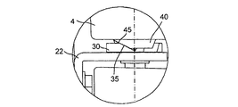
- the left view which shows the refrigerator of embodiment of this invention Detailed view of part A in FIG. Detailed view of part B in FIG.
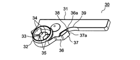
- the perspective view which shows the lower hinge member of the refrigerator of embodiment of this invention
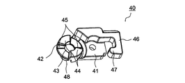
- the perspective view which shows the upper hinge member of the refrigerator of embodiment of this invention
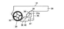
- the top view which shows operation
- the top view which shows operation
- FIG. 1 is a top sectional view showing a refrigerator provided with the door opening / closing mechanism of the first embodiment.
- a storage chamber 3 is formed by a main body 2 having a heat insulating box.
- the opening 3 a on the front surface of the storage chamber 3 is covered with the door 4 on the left side and the door 5 on the right side with respect to the middle.
- a handle 4a, 5a to be gripped by the user is provided at one end of the door 4,5.
- the doors 4 and 5 are pivotally supported by hinge pins 20 that form a rotation shaft at the left and right ends of the main body 2, respectively, and grip the handles 4 a and 5 a so as to open on both sides.
- the door 4 has a front surface covered with a door plate 11 and a rear surface covered with a door back 12. Similarly, the front surface of the door 5 is covered with a door plate 13 and the rear surface thereof is covered with a door back 14.
- Door caps (not shown) are fitted on the upper and lower surfaces of the doors 4 and 5, and the foam insulation 15 is filled inside.
- the door bags 12 and 14 are provided with door pockets (not shown) for storing stored items.
- Packings 6 and 7 are attached to the facing surfaces of the door 4 and the door 5, respectively. Further, packings 16 and 17 are attached to the peripheral portions of the door backs 12 and 14, respectively. The packings 6, 7, 16, and 17 are formed to be expandable and contractible, and a flexible magnet (not shown) is embedded therein. The packings 6 and 7 are attracted to each other to seal the gap between the doors 4 and 5, and the packings 16 and 17 are attracted to the main body 2 to seal between the doors 4 and 5 and the main body 2.
- FIG. 2 shows a left side view of the upper part of the refrigerator 1.
- An upper angle 21 and a lower angle 22 that have hinge pins 20 (see FIG. 1) and support the upper and lower sides of the door 4 are attached to the main body 2 so as to protrude forward.
- the door 4 is demonstrated, the door 5 is also supported similarly.
- FIG. 3 shows a detailed view of part A of FIG.
- the upper angle 21 is made of a metal plate, and a metal hinge pin 20 extends downward and is erected.
- the door 4 is provided with a shaft hole 26 (bearing portion) for pivotally supporting the hinge pin 20 (shaft portion).
- a leaf spring 19 is sandwiched between the seating surface of the hinge pin 20 and the upper surface of the door 4, and the door 4 is biased downward by the leaf spring 19.
- FIG. 4 shows a detailed view of part B of FIG.
- the lower angle 22 is made of a metal plate, and a metal hinge pin 20 (see FIG. 1) extends upward and is erected.
- a lower hinge member 30 (second sliding member) is attached on the lower angle 22.
- An upper hinge member 40 (first sliding member) that is in sliding contact with the lower hinge member 30 is attached to the lower surface of the door 4.
- the upper hinge member 40 is provided with a shaft hole 43 (bearing portion, see FIG. 6) for pivotally supporting the hinge pin 20 (shaft portion).
- the door opening and closing mechanism that pivots the door 4 to open and close is configured by the hinge pins 20, the shaft hole 26, the upper hinge member 40, and the lower hinge member 30 arranged above and below the door 4.
- FIG. 5 shows a perspective view of the lower hinge member 30 as viewed from above.
- the lower hinge member 30 is formed of a resin molded product, and a through hole 33 is provided at one end of a base portion 31 that is screwed to the lower angle 22 (see FIG. 4).
- a hinge pin 20 standing on the lower angle 22 is inserted into the through hole 33.
- a fitting portion 32 having a cylindrical inner wall concentric with the hinge pin 20 is provided around the through hole 33.
- the protrusion part 36 which protrudes from the base part 31 to the radial direction of the hinge pin 20 (through-hole 33) is provided in the outer side of the fitting part 32.
- a notch 38 that is recessed in the peripheral surface of the base portion 31 is formed on the back side of the protrusion 36, and the protrusion 36 and the notch 38 have a common side wall 36a.
- the protrusion 36 is formed to have a length L2 (see FIG. 7) in a direction orthogonal to the side wall 36a, rather than a length L1 (see FIG. 7) of the side wall 36a.
- the protrusion part 36 has high rigidity, and the elastic deformation in the horizontal surface of the protrusion part 36 is prevented.
- the notch 38 is formed continuously with the end edge 37 a on the back side of the inclined surface 37.
- the inclined surface 37 may be formed in a flat surface, or may be formed in a substantially flat surface by a curved surface having a sufficiently large curvature with respect to the radial distance from the hinge pin 20.
- the base portion 31 is provided with a stopper portion 39 that is continuous with the side wall on the back side of the notch portion 38 and faces the edge 37a of the inclined surface 37.
- FIG. 6 shows a perspective view of the upper hinge member 40 as viewed from below.
- the upper hinge member 40 is formed of a resin molded product, and a cylindrical portion 48 protrudes from one end of a base portion 41 that is screwed to the door 4.
- the cylinder part 48 is embedded in the door 4 (see FIG. 4), and a shaft hole 43 is formed therein.
- a hinge pin 20 (see FIG. 1) inserted into the through hole 33 (see FIG. 5) of the lower hinge member 30 is fitted into the shaft hole 43 (bearing portion), and the hinge pin 20 is pivotally supported.
- a convex portion 42 that fits into the fitting portion 32 of the lower hinge member 30 is formed.
- a plurality of flat portions 44 made of a horizontal plane are provided point-symmetrically within a predetermined angle range.
- a plurality of slopes 45 inclined upward with respect to the flat portion 44 are provided in a predetermined angle range continuous to the flat portion 44 in a point-symmetric manner.
- An arm portion 46 extending from the near side to the far side is provided at the end of the base portion 41 opposite to the shaft hole 43.
- the arm portion 46 can be elastically deformed in a horizontal plane perpendicular to the axial direction of the hinge pin 20 (see FIG. 1).
- the arm portion 46 has a sliding contact portion 47 that bends the tip and contacts the inclined surface 37 (see FIG. 5) of the lower hinge member 30.
- the peripheral surface of the sliding contact portion 47 is formed into a curved surface.
- the flat portion 44 of the upper hinge member 40 is disposed on the flat portion 34 of the lower hinge member 30 with the door 4 being opened by a predetermined amount.
- the flat portions 34 and 44 slide to rotate the door 4 within a predetermined rotation range.
- the slope 35 of the lower hinge member 30 and the slope 45 of the upper hinge member 40 start to slide. Thereby, the door 4 rotates in the closing direction while being lowered by the urging force of its own weight, and is self-closed. That is, the slopes 35 and 45 constitute a self-closing mechanism that causes the door 4 to self-close by its own weight in a self-closing section from the sliding start position to the door 4 closing position. At this time, the door 4 can be self-closed more reliably by the urging force of the leaf spring 19. In the self-closing section, the door 4 rotates while being accelerated by its own weight.
- the sliding contact portion 47 in contact with the inclined surface 37 slides with the inclined surface 37 due to elastic deformation of the arm portion 46.
- the elastic force of the arm part 46 increases and the rotational speed of the door 4 decelerates. Therefore, the arm part 46 including the sliding contact part 47 and the inclined surface 37 constitute a speed reducing part that decelerates the rotation of the door 4 when the door 4 is closed.
- the direction of the reaction force applied from the inclined surface 37 to the sliding contact portion 47 by the elastic force of the arm portion 46 becomes substantially constant.
- the circumferential direction component of the hinge pin 20 of the reaction force applied to the sliding contact portion 47 works as a force for decelerating the door 4. For this reason, even if the position where the inclined surface 37 and the sliding contact portion 47 abut changes depending on the dimensional accuracy of the lower hinge member 30 and the upper hinge member 40, the circumferential component of the reaction force in a substantially constant direction is applied to the door 4. It is done. Thereby, the door 4 can be decelerated reliably. Further, since the protrusion 36 has high rigidity, it is possible to prevent the protrusion 36 from elastically deforming and changing the direction of the reaction force applied to the sliding contact portion 47.
- the door 4 Since the door 4 is disposed at the closed position after the rotational speed is reduced by sliding between the inclined surface 37 and the sliding contact portion 47, it is possible to reduce the impact sound at the time of the collision between the door 4 and the main body portion 2. Moreover, the contact sound of the stored matter stored in the door 4 due to the impact at the time of the collision between the door 4 and the main body 2 can be reduced. Therefore, noise when the door 4 is closed can be reduced.
- the arm portion 46 since the sliding contact portion 47 enters the cutout portion 38 and the elastic force of the arm portion 46 is reduced, the arm portion 46 needs to be elastically deformed in order to rotate the door 4 in the opening direction. . For this reason, it is possible to prevent the door 4 from colliding with the main body 2 at the closed position.
- the doors 4 and 5 are accelerated and self-closed by the self-closing mechanism formed by the slopes 35 and 45.
- the upper hinge member 40 first sliding member
- the lower hinge member 30 second sliding member
- An inclined surface 37 is provided that is inclined in a direction to increase the elastic force of the arm portion 46 when closed.
- the doors 4 and 5 are decelerated by sliding between the inclined surface 37 and the sliding contact portion 47. Thereby, the doors 4 and 5 that are accelerated and self-closed can be decelerated by the speed reducing portion having the inclined surface 37 and the sliding contact portion 47 to reduce noise when the doors 4 and 5 are closed.
- the sliding contact portion 47 enters the cutout portion 38 provided in the lower hinge member 30 and the elastic force of the arm portion 46 is reduced, and the arm portion 46 abuts against the stopper portion 39 in an elastically deformed state to cause the doors 4, 5. Is closed. For this reason, the work amount at the time of opening the doors 4 and 5 against the elastic force of the arm portion 46 can be reduced. Therefore, the doors 4 and 5 can be opened easily, and the convenience of the refrigerator 1 provided with the door opening / closing mechanism can be improved.
- the inclined surface 37 is formed in a substantially flat surface within a sliding range with the sliding contact portion 47 of the upper hinge member 40.
- the sliding contact portion 47 comes into contact with the stopper portion 39 as the elastic force of the arm portion 46 decreases while sliding on the end edge 37 a of the boundary between the inclined surface 37 and the notch portion 38.
- the direction of the reaction force applied to the sliding contact portion 47 can be made substantially constant until the sliding contact portion 47 reaches the end edge 37a of the inclined surface 37 and the elastic force of the arm portion 46 starts to decrease. Therefore, the door 4 can be surely decelerated even if the position where the inclined surface 37 and the slidable contact portion 47 abut changes depending on the dimensional accuracy of the lower hinge member 30 and the upper hinge member 40.
- the length L2 of the protrusion 36 in the direction orthogonal to the side wall 36a is larger than the length L1 of the side wall 36a common to the protrusion 36 and the notch 38, the rigidity of the protrusion 36 can be increased. Therefore, it is possible to prevent the protruding portion 36 from being elastically deformed and to change the direction of the reaction force applied to the sliding contact portion 47, and to make the direction of the reaction force constant more reliably.
- the self-closing mechanism part which self-closes the doors 4 and 5 is comprised by the slopes 35 and 45 provided in the lower hinge member 30 and the upper hinge member 40, and the doors 4 and 5 are closed in the direction which accelerates and descends with dead weight. To turn. Thereby, the self-closing mechanism part which accelerates the doors 4 and 5 and self-closes can be implement
- the packings 16 and 17 are provided in close contact with the main body 2 when the doors 4 and 5 are closed, the impact when the doors 4 and 5 are closed can be further reduced by the elasticity of the packings 16 and 17.
- the packings 16 and 17 and the main body 2 are separated from each other at the open ends of the doors 4 and 5 when the sliding between the inclined surface 37 and the sliding contact portion 47 is started, the rotation speed of the doors 4 and 5 is increased. After the speed is reduced, the packings 16 and 17 come into contact with the main body 2. Therefore, the collision sound between the packings 16 and 17 and the main body 2 can be reduced.
- one of the slopes 35 and 45 of the first embodiment is formed vertically.
- the doors 4 and 5 can be accelerated by their own weight and can be closed automatically. Therefore, the same effect as the first embodiment can be obtained.
- the doors 4 and 5 of the refrigerator 1 of the first embodiment are accelerated and self-closed by their own weight, but the door opening and closing mechanism of the refrigerator 1 of the present embodiment is an elastic member such as a spring that biases the doors 4 and 5 in the closing direction. Is provided.
- the doors 4 and 5 are accelerated and self-closed by the elastic force of the elastic member. Therefore, the same effect as the first embodiment can be obtained.
- the same effect can be acquired also in the door opening / closing mechanism which has arrange
- the hinge pin 20 may be provided in the doors 4 and 5, and the shaft holes 26 and 43 may be provided in the main body 2. Further, the protruding portion 36 having the inclined surface 37, the cutout portion 38 and the stopper portion 39 may be provided on the doors 4 and 5, and the arm portion 46 and the sliding contact portion 47 may be provided on the main body portion 2.
- the present invention can be used for a door opening / closing mechanism having a self-closing function of a door and a refrigerator equipped with the door opening / closing mechanism.
Landscapes
- Engineering & Computer Science (AREA)
- Mechanical Engineering (AREA)
- Chemical & Material Sciences (AREA)
- Combustion & Propulsion (AREA)
- Physics & Mathematics (AREA)
- Thermal Sciences (AREA)
- General Engineering & Computer Science (AREA)
- Refrigerator Housings (AREA)
- Closing And Opening Devices For Wings, And Checks For Wings (AREA)
Abstract
軸部20と軸受部43とによって扉4、5を枢支して開閉させる扉開閉機構において、所定の自閉区間で扉4、5を付勢により加速して自閉させる自閉機構部と、第1摺動部材40と第2摺動部材30との摺動により扉4、5の自閉時の回動を減速させる減速部とを備え、第1摺動部材40が軸部20の軸方向に垂直な面内で弾性変形可能に形成されるとともに、第2摺動部材30が、扉4、5を閉じる際に軸部20の周方向に対して第1摺動部材40の弾性力を増加させる方向に傾斜する傾斜面37と、扉4、5を閉じる際に傾斜面37を通過した第1摺動部材40が弾性力の減少方向に進入する切欠部38と、扉4、5の閉止位置で第1摺動部材40が弾性変形状態で当接して扉4、5の回動を停止させるストッパ部39とを有する。
Description
本発明は、扉の自閉機能を有する扉開閉機構及びそれを備えた冷蔵庫に関する。
扉を自閉させる扉開閉機構を備えた冷蔵庫は特許文献1に開示されている。この冷蔵庫は貯蔵室を有した本体部の左右端にそれぞれ鉛直な回動軸を形成する軸部(ヒンジピン)によって扉が枢支される。軸部は貯蔵室の周壁の上下面からそれぞれ突出して設けられ、扉の上下面には軸部に嵌合して軸部を回転自在に支持する軸受部が設けられる。
扉の下面には軸受部を一体に形成した上ヒンジ部材が取り付けられる。本体部には軸部を一体に形成して上ヒンジ部材に対向する下ヒンジ部材が取り付けられる。上ヒンジ部材及び下ヒンジ部材は軸部の周囲の水平面内で互いに摺動し、扉が鉛直方向に支持される。
また、上ヒンジ部材及び下ヒンジ部材には所定の回動範囲にスロープが対向して設けられる。両スロープの摺動によって扉が開かれる際に上昇し、閉じられる際に降下する。この時、スロープが摺動する位置まで使用者が扉を閉じると扉が自重によってスロープに沿って降下して閉止位置に配される。これにより、扉を自閉させる自閉機構が構成され、冷蔵庫の利便性が向上する。
しかしながら、上記従来の扉開閉機構によると、扉が自閉する際に自重により加速して回動するため、扉と本体部とが衝突した際に衝撃音が発生する。また、扉と本体部との衝突時の衝撃によって扉に収納した貯蔵物の接触音が発生する。従って、扉の自閉時の騒音が大きくなる問題があった。特に、本体部の左右端で枢支される複数の扉を有する場合には、一方の扉を開いて他方の扉を閉じると貯蔵物の接触音が外部に漏れやすくなるため騒音がより大きくなる。
本発明は、扉の自閉時の騒音を低減できる扉開閉機構及びそれを用いた冷蔵庫を提供することを目的とする。
上記目的を達成するために本発明は、本体部及び扉の一方に設けられる軸部と他方に設けられる軸受部とによって前記扉を枢支して開閉させる扉開閉機構において、所定の自閉区間で前記扉を付勢により加速して自閉させる自閉機構部と、前記本体部及び前記扉の一方に設けられる第1摺動部材と他方に設けられる第2摺動部材との摺動により前記扉の自閉時の回動を減速させる減速部とを備え、
第1摺動部材が前記軸部の軸方向に垂直な面内で弾性変形可能に形成されるとともに、第2摺動部材が、前記扉を閉じる際に前記軸部の周方向に対して第1摺動部材の弾性力を増加させる方向に傾斜する傾斜面と、前記扉を閉じる際に前記傾斜面を通過した第1摺動部材が弾性力の減少方向に進入する切欠部と、前記扉の閉止位置で第1摺動部材が弾性変形状態で当接して前記扉の回動を停止させるストッパ部とを有することを特徴としている。
第1摺動部材が前記軸部の軸方向に垂直な面内で弾性変形可能に形成されるとともに、第2摺動部材が、前記扉を閉じる際に前記軸部の周方向に対して第1摺動部材の弾性力を増加させる方向に傾斜する傾斜面と、前記扉を閉じる際に前記傾斜面を通過した第1摺動部材が弾性力の減少方向に進入する切欠部と、前記扉の閉止位置で第1摺動部材が弾性変形状態で当接して前記扉の回動を停止させるストッパ部とを有することを特徴としている。
この構成によると、扉を自閉区間の開始位置まで閉じると自閉機構部により扉が自閉を開始する。所定位置まで扉が自閉すると第1摺動部材が第2摺動部材の傾斜面との摺動により弾性変形し、扉の回動速度が減速する。第1摺動部材が傾斜面を通過して切欠部に進入すると弾性力が低下し、ストッパ部に当接して扉が閉止状態に配される。
また本発明は、上記構成の扉開閉機構において、前記傾斜面が第1摺動部材との摺動範囲で略平面に形成され、第1摺動部材が前記傾斜面と前記切欠部との境界に摺動した状態で、弾性力が減少して前記ストッパ部に当接することを特徴としている。
また本発明は、上記構成の扉開閉機構において、第2摺動部材が前記本体部または前記扉に取り付けられる基台部と、前記基台部から前記軸部の径方向に突出する突出部とを有し、前記突出部の先端に前記傾斜面を形成するとともに一方の側壁により前記切欠部の壁面が形成され、該側壁の長さよりも該側壁に直交する方向の前記突出部の長さが大きいことを特徴としている。
また本発明は、上記構成の扉開閉機構において、前記軸部が鉛直に配されるとともに、第1摺動部材及び第2摺動部材が前記扉の下面及び前記本体部にそれぞれ配して前記軸部の周囲の水平面内で前記扉の回動時に互いに摺動し、前記自閉機構部は第1摺動部材及び第2摺動部材の少なくとも一方に設けられるとともに水平面に対して傾斜するスロープから成り、前記スロープによって前記扉が自重で加速して降下しながら閉じる方向に回動することを特徴としている。
また本発明の冷蔵庫は、上記各構成の扉開閉機構と、前記本体部に設けられて前記扉により前面を開閉される貯蔵室と、前記扉の周部に配して前記扉の閉止時に前記本体部に密接するパッキンとを備えたしている。
また本発明は、上記構成の冷蔵庫において、第1摺動部材と第2摺動部材との摺動による減速が開始された時に前記扉の開放端で前記パッキンと前記本体部とが離れていることを特徴としている。
また本発明は、上記構成の冷蔵庫において、前記扉を複数設け、各前記扉が前記貯蔵室の左右端でそれぞれ枢支されることを特徴としている。
本発明によると、加速して自閉する扉を減速させる減速部が第1、第2摺動部材を備える。また、第2摺動部材が、自閉時に弾性変形可能な第1摺動部材の弾性力を増加させる傾斜面と、第1摺動部材が弾性力の減少方向に進入する切欠部と、第1摺動部材が弾性変形状態で当接するストッパ部とを有する。これにより、加速して自閉する扉を減速部により減速して扉の閉止時の騒音を低減することができる。また、第1摺動部材が弾性変形状態でストッパ部に当接するため、第1摺動部材の弾性力に抗して扉を開く際の仕事量を小さくできる。従って、扉を容易に開くことができ、扉開閉機構を設けた機器の利便性を向上することができる。
<第1実施形態>
以下に図面を参照して本発明の実施形態を説明する。図1は第1実施形態の扉開閉機構を備えた冷蔵庫を示す上面断面図である。冷蔵庫1は断熱箱体を有する本体部2により貯蔵室3が形成される。貯蔵室3の前面の開口部3aは中程を境に左側を扉4により覆われ、右側を扉5により覆われている。
以下に図面を参照して本発明の実施形態を説明する。図1は第1実施形態の扉開閉機構を備えた冷蔵庫を示す上面断面図である。冷蔵庫1は断熱箱体を有する本体部2により貯蔵室3が形成される。貯蔵室3の前面の開口部3aは中程を境に左側を扉4により覆われ、右側を扉5により覆われている。
扉4、5の一端には使用者が把持する把手4a、5aが設けられている。扉4、5はそれぞれ本体部2の左右の端部で回動軸を形成するヒンジピン20により枢支され、把手4a、5aを把持して両側に開くようになっている。
扉4は前面をドアプレート11により覆われ、背面をドアバック12により覆われる。同様に、扉5は前面をドアプレート13により覆われ、背面をドアバック14により覆われる。扉4、5の上下面にはドアキャップ(不図示)が被嵌され、内部に発泡断熱材15が充填される。ドアバック12、14には貯蔵物を収納するドアポケット(不図示)が設けられる。
扉4と扉5の対向面にはそれぞれパッキン6、7が取り付けられる。また、ドアバック12、14の周部にはそれぞれパッキン16、17が取り付けられる。パッキン6、7、16、17は伸縮可能に形成され、内部に可撓性の磁石(不図示)が埋め込まれる。パッキン6、7が互いに吸着して扉4、5間の隙間が密閉され、パッキン16、17が本体部2に吸着して扉4、5と本体部2との間が密閉される。
図2は冷蔵庫1の上部の左側面図を示している。本体部2にはヒンジピン20(図1参照)を有して扉4の上下を支持する上アングル21及び下アングル22が前方に突出して取り付けられる。以下、扉4について説明するが、扉5も同様に支持される。
図3は図2のA部詳細図を示している。上アングル21は金属板から成り、金属製のヒンジピン20が下方に延びて立設される。扉4にはヒンジピン20(軸部)を軸支する軸孔26(軸受部)が設けられる。ヒンジピン20の座面と扉4の上面との間には板バネ19が挟持され、板バネ19により扉4が下方に付勢される。
図4は図2のB部詳細図を示している。下アングル22は金属板から成り、金属製のヒンジピン20(図1参照)が上方に延びて立設される。下アングル22上には下ヒンジ部材30(第2摺動部材)が取り付けられる。扉4の下面には下ヒンジ部材30に摺接する上ヒンジ部材40(第1摺動部材)が取り付けられる。上ヒンジ部材40にはヒンジピン20(軸部)を軸支する軸孔43(軸受部、図6参照)が設けられる。
扉4の上下に配したヒンジピン20、軸孔26、上ヒンジ部材40及び下ヒンジ部材30により、扉4を枢支して開閉させる扉開閉機構が構成される。
図5は下ヒンジ部材30を上方から見た斜視図を示している。下ヒンジ部材30は樹脂成形品により形成され、下アングル22(図4参照)にネジ止めされる基台部31の一端に貫通孔33が設けられる。貫通孔33には下アングル22に立設したヒンジピン20(図1参照)が挿通される。
貫通孔33の周囲にはヒンジピン20と同心の円筒面の内壁を有する嵌合部32が設けられる。ヒンジピン20の座面を形成する嵌合部32の底面には所定の角度範囲に水平面から成る複数の平坦部34が点対称に設けられる。また、平坦部34に連続する所定の角度範囲には平坦部34に対して下方に傾斜する複数のスロープ35が点対称に設けられる。
嵌合部32の外側には基台部31からヒンジピン20(貫通孔33)の径方向に突出する突出部36が設けられる。突出部36の奥側には基台部31の周面に凹設される切欠部38が形成され、突出部36と切欠部38とは共通の側壁36aを有する。突出部36は側壁36aの長さL1(図7参照)よりも側壁36aに直交する方向の長さL2(図7参照)が大きく形成される。これにより、突出部36が高い剛性を有し、突出部36の水平面内での弾性変形が防止される。
突出部36の先端にはヒンジピン20(貫通孔33)の周方向に対して傾斜した略平面の傾斜面37が形成される。傾斜面37は奥側のヒンジピン20からの径方向の距離が手前側に対して大きくなっている。切欠部38は傾斜面37の奥側の端縁37aに連続して形成される。傾斜面37は平面に形成してもよく、ヒンジピン20からの径方向の距離に対して十分大きい曲率を有した曲面により略平面に形成してもよい。
また、基台部31には切欠部38の奥側の側壁に連続して傾斜面37の端縁37aに対向するストッパ部39が設けられる。
図6は上ヒンジ部材40を下方から見た斜視図を示している。上ヒンジ部材40は樹脂成形品により形成され、扉4にネジ止めされる基台部41の一端に筒部48が突設される。筒部48は扉4(図4参照)内に埋設され、内部に軸孔43が形成される。軸孔43(軸受部)は下ヒンジ部材30の貫通孔33(図5参照)に挿通したヒンジピン20(図1参照)が嵌合し、ヒンジピン20を軸支する。
軸孔43の周囲には下ヒンジ部材30の嵌合部32に嵌合する凸部42が形成される。凸部42の下面には所定の角度範囲に水平面から成る複数の平坦部44が点対称に設けられる。また、平坦部44に連続する所定の角度範囲には平坦部44に対して上方に傾斜する複数のスロープ45が点対称に設けられる。
基台部41の軸孔43と反対側の端部には手前側から奥側に延びる腕部46が設けられる。腕部46はヒンジピン20(図1参照)の軸方向に垂直な水平面内で弾性変形可能になっている。腕部46は先端を屈曲して下ヒンジ部材30の傾斜面37(図5参照)に摺接する摺接部47を有している。摺接部47の周面は曲面に形成される。
上記構成の冷蔵庫1において、扉4が所定量開かれた状態で下ヒンジ部材30の平坦部34上に上ヒンジ部材40の平坦部44が配される。平坦部34、44が摺動して扉4が所定の回動範囲で回動する。
扉4を閉じる方向に回動させると、下ヒンジ部材30のスロープ35と上ヒンジ部材40のスロープ45とが摺動を開始する。これにより、扉4は自重の付勢力によって降下しながら閉じる方向に回動して自閉する。即ち、スロープ35、45は摺動開始位置から扉4の閉止位置までの自閉区間で扉4を自重により自閉させる自閉機構部を構成する。この時、板バネ19の付勢力によってより確実に扉4を自閉させることができる。自閉区間では扉4は自重によって加速しながら回動する。
図7の平面図に示すように、扉4の自閉によって上ヒンジ部材40の摺接部47が下ヒンジ部材30の傾斜面37に当接する。この時、扉4の開放端でパッキン16と本体部2とが離れている。
傾斜面37に当接した摺接部47は腕部46の弾性変形によって傾斜面37と摺動する。これにより、腕部46の弾性力が増加し、扉4の回動速度が減速する。従って、摺接部47を含む腕部46と傾斜面37とは扉4の自閉時の回動を減速させる減速部を構成する。
この時、傾斜面37が略平面に形成されるため、腕部46の弾性力によって傾斜面37から摺接部47に加わる反力の方向が略一定になる。摺接部47に加わる該反力のヒンジピン20の周方向成分が扉4を減速させる力として働く。このため、下ヒンジ部材30及び上ヒンジ部材40の寸法精度によって傾斜面37と摺接部47の当接する位置が変化しても、略一定方向の該反力の周方向成分が扉4に加えられる。これにより、確実に扉4を減速させることができる。また、突出部36の剛性が高いため、突出部36が弾性変形して摺接部47に加わる反力の方向が変動することを防止できる。
図8に示すように、扉4の自閉により摺接部47が傾斜面37の端縁37aに到達すると、摺接部47は端縁37aと摺動しながら切欠部38の内部に進入する。これにより、腕部46の弾性力が減少する。
図9に示すように更に扉4が回動すると、切欠部38に進入した摺接部47が端縁37aに摺動した状態でストッパ部39に当接する。これにより、扉4が停止して閉止位置に配され、パッキン16が本体部2に接触して貯蔵室3を密閉する。この時、摺接部47の手前側の周面は傾斜面37の端縁37aに当接しており、腕部46は弾性変形状態を維持している。
扉4は傾斜面37と摺接部47との摺動により回転速度を減速した後に閉止位置に配されるので、扉4と本体部2との衝突時の衝撃音を低減することができる。また、扉4と本体部2との衝突時の衝撃による扉4に収納した貯蔵物の接触音を低減することができる。従って、扉4の閉止時の騒音を低減することができる。
また、摺接部47が切欠部38内に進入して腕部46の弾性力が減少しているため、扉4を開く方向に回動させるためには腕部46を弾性変形させる必要がある。このため、閉止位置で本体部2と衝突した扉4のバウンドを防止することができる。
閉止位置の扉4が扉4の自重及び腕部46の弾性力に抗して開かれると、スロープ35、45が摺動して扉4が持ち上げられる。この時、扉4の閉止位置で腕部46が弾性変形状態を維持するので、腕部46の弾性力に抗して扉4を開く際の仕事量を小さくできる。扉4が自閉区間を通過すると上ヒンジ部材40の平坦部44が下ヒンジ部材30の平坦部34に乗り上げる。その後、平坦部34、44が摺動して扉4が開かれる。
尚、扉4の開閉時の動作について説明したが、扉5の開閉時の動作も同様である。
本実施形態によると、スロープ35、45により形成される自閉機構部によって扉4、5が加速して自閉する。上ヒンジ部材40(第1摺動部材)には弾性変形可能な腕部46の先端に摺接部47が設けられ、下ヒンジ部材30(第2摺動部材)には扉4、5の自閉時に腕部46の弾性力を増加させる方向に傾斜した傾斜面37が設けられる。そして、傾斜面37と摺接部47との摺動により扉4、5を減速させる。これにより、加速して自閉する扉4、5を傾斜面37及び摺接部47を有した減速部により減速して扉4、5の閉止時の騒音を低減することができる。
また、下ヒンジ部材30に設けた切欠部38に摺接部47が進入して腕部46の弾性力が減少し、腕部46が弾性変形状態でストッパ部39に当接して扉4、5が閉止される。このため、腕部46の弾性力に抗して扉4、5を開く際の仕事量を小さくできる。従って、扉4、5を容易に開くことができ、扉開閉機構を設けた冷蔵庫1の利便性を向上することができる。
また、傾斜面37が上ヒンジ部材40の摺接部47との摺動範囲で略平面に形成される。摺接部47は傾斜面37と切欠部38との境界の端縁37aに摺動した状態で腕部46の弾性力が減少してストッパ部39に当接する。このため、摺接部47が傾斜面37の端縁37aに到達して腕部46の弾性力が減少し始めるまで、摺接部47に加わる反力の方向を略一定することができる。従って、下ヒンジ部材30及び上ヒンジ部材40の寸法精度によって傾斜面37と摺接部47の当接する位置が変化しても確実に扉4を減速させることができる。
また、突出部36と切欠部38と共通の側壁36aの長さL1よりも側壁36aに直交する方向の突出部36の長さL2が大きいので、突出部36の剛性を高くすることができる。従って、突出部36が弾性変形して摺接部47に加わる反力の方向が変動することを防止でき、該反力の方向をより確実に一定にすることができる。
また、扉4、5を自閉させる自閉機構部が下ヒンジ部材30及び上ヒンジ部材40に設けたスロープ35、45により構成され、扉4、5が自重で加速して降下しながら閉じる方向に回動する。これにより、扉4、5を加速して自閉させる自閉機構部を容易に実現することができる。
また、扉4、5の閉止時に本体部2に密接するパッキン16、17を設けたので、パッキン16、17の弾性によって扉4、5を閉じた際の衝撃をより低減することができる。
また、傾斜面37と摺接部47との摺動が開始された時に扉4、5の開放端でパッキン16、17と本体部2とが離れているので、扉4、5の回動速度を減速した後にパッキン16、17が本体部2に当接する。従って、パッキン16、17と本体部2との衝突音を低減することができる。
また、貯蔵室3の左右端で枢支される扉4、5を備えるので、扉4、5の両方を開いた状態から一方を閉じた際に扉4、5に収納される貯蔵物の接触音が外部に漏れやすくなる。このため、自閉する扉4、5を減速部により減速することで騒音低減に対してより大きな効果を奏する。
<第2実施形態>
次に、第2実施形態について説明する。本実施形態の冷蔵庫1は第1実施形態のスロープ35、45の一方が鉛直に形成される。これにより、扉4、5が自重により加速して自閉することができる。従って、第1実施形態と同様の効果を得ることができる。
次に、第2実施形態について説明する。本実施形態の冷蔵庫1は第1実施形態のスロープ35、45の一方が鉛直に形成される。これにより、扉4、5が自重により加速して自閉することができる。従って、第1実施形態と同様の効果を得ることができる。
<第3実施形態>
次に、第3実施形態について説明する。第1実施形態の冷蔵庫1の扉4、5は自重により加速して自閉するが、本実施形態の冷蔵庫1の扉開閉機構は扉4、5を閉じる方向に付勢するバネ等の弾性部材が設けられる。弾性部材の弾性力により扉4、5が加速して自閉する。従って、第1実施形態と同様の効果を得ることができる。尚、弾性部材を設ける場合は扉4、5の回動軸を水平に配置した扉開閉機構においても同様の効果を得ることができる。
次に、第3実施形態について説明する。第1実施形態の冷蔵庫1の扉4、5は自重により加速して自閉するが、本実施形態の冷蔵庫1の扉開閉機構は扉4、5を閉じる方向に付勢するバネ等の弾性部材が設けられる。弾性部材の弾性力により扉4、5が加速して自閉する。従って、第1実施形態と同様の効果を得ることができる。尚、弾性部材を設ける場合は扉4、5の回動軸を水平に配置した扉開閉機構においても同様の効果を得ることができる。
第1~第3実施形態において、ヒンジピン20を扉4、5に設け、軸孔26、43を本体部2に設けてもよい。また、傾斜面37を有する突出部36、切欠部38及びストッパ部39を扉4、5に設け、腕部46及び摺接部47を本体部2に設けてもよい。
本発明は、扉の自閉機能を有する扉開閉機構及びそれを備えた冷蔵庫等に利用することができる。
1 冷蔵庫
2 本体部
3 貯蔵室
3a 開口部
4、5 扉
6、7、16、17 パッキン
11、13 ドアプレート
12、14 ドアバック
15 発泡断熱材
19 板バネ
20 ヒンジピン
21 上アングル
22 下アングル
26、43 軸孔
30 下ヒンジ部材
31 基台部
32 嵌合部
33 貫通孔
34、44 平坦部
35、45 スロープ
36 突出部
36a 側壁
37 傾斜面
37a 端縁
38 切欠部
39 ストッパ部
40 上ヒンジ部材
41 基台部
42 凸部
46 腕部
47 摺接部
48 筒部
2 本体部
3 貯蔵室
3a 開口部
4、5 扉
6、7、16、17 パッキン
11、13 ドアプレート
12、14 ドアバック
15 発泡断熱材
19 板バネ
20 ヒンジピン
21 上アングル
22 下アングル
26、43 軸孔
30 下ヒンジ部材
31 基台部
32 嵌合部
33 貫通孔
34、44 平坦部
35、45 スロープ
36 突出部
36a 側壁
37 傾斜面
37a 端縁
38 切欠部
39 ストッパ部
40 上ヒンジ部材
41 基台部
42 凸部
46 腕部
47 摺接部
48 筒部
Claims (5)
- 本体部及び扉の一方に設けられる軸部と他方に設けられる軸受部とによって前記扉を枢支して開閉させる扉開閉機構において、所定の自閉区間で前記扉を付勢により加速して自閉させる自閉機構部と、前記本体部及び前記扉の一方に設けられる第1摺動部材と他方に設けられる第2摺動部材との摺動により前記扉の自閉時の回動を減速させる減速部とを備え、
第1摺動部材が前記軸部の軸方向に垂直な面内で弾性変形可能に形成されるとともに、第2摺動部材が、前記扉を閉じる際に前記軸部の周方向に対して第1摺動部材の弾性力を増加させる方向に傾斜する傾斜面と、前記扉を閉じる際に前記傾斜面を通過した第1摺動部材が弾性力の減少方向に進入する切欠部と、前記扉の閉止位置で第1摺動部材が弾性変形状態で当接して前記扉の回動を停止させるストッパ部とを有することを特徴とする扉開閉機構。 - 前記傾斜面が第1摺動部材との摺動範囲で略平面に形成され、第1摺動部材が前記傾斜面と前記切欠部との境界に摺動した状態で、弾性力が減少して前記ストッパ部に当接することを特徴とする請求項1に記載の扉開閉機構。
- 第2摺動部材が前記本体部または前記扉に取り付けられる基台部と、前記基台部から前記軸部の径方向に突出する突出部とを有し、前記突出部の先端に前記傾斜面を形成するとともに一方の側壁により前記切欠部の壁面が形成され、該側壁の長さよりも該側壁に直交する方向の前記突出部の長さが大きいことを特徴とする請求項1または請求項2に記載の扉開閉機構。
- 前記軸部が鉛直に配されるとともに、第1摺動部材及び第2摺動部材が前記扉の下面及び前記本体部にそれぞれ配して前記軸部の周囲の水平面内で前記扉の回動時に互いに摺動し、前記自閉機構部は第1摺動部材及び第2摺動部材の少なくとも一方に設けられるとともに水平面に対して傾斜するスロープから成り、前記スロープによって前記扉が自重で加速して降下しながら閉じる方向に回動することを特徴とする請求項1~請求項3のいずれかに記載の扉開閉機構。
- 請求項1~請求項4のいずれかに記載の扉開閉機構と、前記本体部に設けられて前記扉により前面を開閉される貯蔵室と、前記扉の周部に配して前記扉の閉止時に前記本体部に密接するパッキンとを備え、第1摺動部材と第2摺動部材との摺動による減速が開始された時に前記扉の開放端で前記パッキンと前記本体部とが離れていることを特徴とする冷蔵庫。
Priority Applications (1)
| Application Number | Priority Date | Filing Date | Title |
|---|---|---|---|
| CN201480029627.8A CN105229398B (zh) | 2013-06-20 | 2014-06-20 | 门开关机构和冰箱 |
Applications Claiming Priority (2)
| Application Number | Priority Date | Filing Date | Title |
|---|---|---|---|
| JP2013129885A JP6125923B2 (ja) | 2013-06-20 | 2013-06-20 | 扉開閉機構及び冷蔵庫 |
| JP2013-129885 | 2013-06-20 |
Publications (1)
| Publication Number | Publication Date |
|---|---|
| WO2014203993A1 true WO2014203993A1 (ja) | 2014-12-24 |
Family
ID=52104719
Family Applications (1)
| Application Number | Title | Priority Date | Filing Date |
|---|---|---|---|
| PCT/JP2014/066420 Ceased WO2014203993A1 (ja) | 2013-06-20 | 2014-06-20 | 扉開閉機構及び冷蔵庫 |
Country Status (4)
| Country | Link |
|---|---|
| JP (1) | JP6125923B2 (ja) |
| CN (1) | CN105229398B (ja) |
| MY (1) | MY187892A (ja) |
| WO (1) | WO2014203993A1 (ja) |
Cited By (3)
| Publication number | Priority date | Publication date | Assignee | Title |
|---|---|---|---|---|
| CN108332495A (zh) * | 2017-12-29 | 2018-07-27 | 青岛海尔股份有限公司 | 一种冰箱门体及冰箱 |
| US10584524B2 (en) * | 2014-07-25 | 2020-03-10 | Bsh Hausgeraete Gmbh | Domestic refrigerator having a closing cam which has a coupling projection with a recess |
| JP2024020549A (ja) * | 2018-09-12 | 2024-02-14 | シャープ株式会社 | 扉開閉機構および冷蔵庫 |
Families Citing this family (5)
| Publication number | Priority date | Publication date | Assignee | Title |
|---|---|---|---|---|
| CN110892218B (zh) | 2017-07-26 | 2021-10-12 | 夏普株式会社 | 门开闭机构 |
| KR20220018705A (ko) | 2020-08-07 | 2022-02-15 | 엘지전자 주식회사 | 냉장고 |
| CN115479440B (zh) * | 2021-06-16 | 2024-04-19 | 青岛海尔制冷电器有限公司 | 冰箱 |
| US12006752B1 (en) * | 2023-02-21 | 2024-06-11 | Hangzhou Jinsong Euna Electrical Appliances Co., Ltd. | Door limiting mechanism and electric appliance cabinet |
| KR20240136532A (ko) * | 2023-03-07 | 2024-09-19 | 엘지전자 주식회사 | 냉장고 |
Citations (6)
| Publication number | Priority date | Publication date | Assignee | Title |
|---|---|---|---|---|
| JPH0564687U (ja) * | 1992-01-31 | 1993-08-27 | 株式会社富士通ゼネラル | 冷蔵庫の扉開閉機構 |
| JP2001174139A (ja) * | 1999-12-14 | 2001-06-29 | Matsushita Refrig Co Ltd | 冷蔵庫 |
| JP2007024460A (ja) * | 2005-07-21 | 2007-02-01 | Sharp Corp | 扉開閉機構及び冷蔵庫 |
| JP2007101180A (ja) * | 2007-01-24 | 2007-04-19 | Hitachi Appliances Inc | 冷蔵庫 |
| US20080203739A1 (en) * | 2007-02-26 | 2008-08-28 | Samsung Electronics Co., Ltd. | Mixed type refrigerator with unit to keep doors closed |
| JP2011058780A (ja) * | 2009-09-14 | 2011-03-24 | Hitachi Appliances Inc | 冷蔵庫 |
Family Cites Families (4)
| Publication number | Priority date | Publication date | Assignee | Title |
|---|---|---|---|---|
| US5458412A (en) * | 1992-10-31 | 1995-10-17 | Samsung Electronics Co., Ltd. | Door opening/closing apparatus for a refrigerator |
| KR100755320B1 (ko) * | 2005-05-27 | 2007-09-05 | 엘지전자 주식회사 | 냉장고의 도어 개폐 장치 |
| JP4904222B2 (ja) * | 2007-08-20 | 2012-03-28 | シャープ株式会社 | 扉開閉機構及び冷蔵庫 |
| CN102337794B (zh) * | 2011-07-26 | 2013-08-14 | 合肥美的荣事达电冰箱有限公司 | 用于打开和关闭箱体的箱门及具有其的冰箱 |
-
2013
- 2013-06-20 JP JP2013129885A patent/JP6125923B2/ja active Active
-
2014
- 2014-06-20 WO PCT/JP2014/066420 patent/WO2014203993A1/ja not_active Ceased
- 2014-06-20 MY MYPI2015002876A patent/MY187892A/en unknown
- 2014-06-20 CN CN201480029627.8A patent/CN105229398B/zh active Active
Patent Citations (6)
| Publication number | Priority date | Publication date | Assignee | Title |
|---|---|---|---|---|
| JPH0564687U (ja) * | 1992-01-31 | 1993-08-27 | 株式会社富士通ゼネラル | 冷蔵庫の扉開閉機構 |
| JP2001174139A (ja) * | 1999-12-14 | 2001-06-29 | Matsushita Refrig Co Ltd | 冷蔵庫 |
| JP2007024460A (ja) * | 2005-07-21 | 2007-02-01 | Sharp Corp | 扉開閉機構及び冷蔵庫 |
| JP2007101180A (ja) * | 2007-01-24 | 2007-04-19 | Hitachi Appliances Inc | 冷蔵庫 |
| US20080203739A1 (en) * | 2007-02-26 | 2008-08-28 | Samsung Electronics Co., Ltd. | Mixed type refrigerator with unit to keep doors closed |
| JP2011058780A (ja) * | 2009-09-14 | 2011-03-24 | Hitachi Appliances Inc | 冷蔵庫 |
Cited By (4)
| Publication number | Priority date | Publication date | Assignee | Title |
|---|---|---|---|---|
| US10584524B2 (en) * | 2014-07-25 | 2020-03-10 | Bsh Hausgeraete Gmbh | Domestic refrigerator having a closing cam which has a coupling projection with a recess |
| CN108332495A (zh) * | 2017-12-29 | 2018-07-27 | 青岛海尔股份有限公司 | 一种冰箱门体及冰箱 |
| JP2024020549A (ja) * | 2018-09-12 | 2024-02-14 | シャープ株式会社 | 扉開閉機構および冷蔵庫 |
| JP7615280B2 (ja) | 2018-09-12 | 2025-01-16 | シャープ株式会社 | 扉開閉機構および冷蔵庫 |
Also Published As
| Publication number | Publication date |
|---|---|
| CN105229398B (zh) | 2017-06-13 |
| JP2015004472A (ja) | 2015-01-08 |
| JP6125923B2 (ja) | 2017-05-10 |
| MY187892A (en) | 2021-10-27 |
| CN105229398A (zh) | 2016-01-06 |
Similar Documents
| Publication | Publication Date | Title |
|---|---|---|
| JP6125923B2 (ja) | 扉開閉機構及び冷蔵庫 | |
| JP5535580B2 (ja) | 自動開閉扉蝶番 | |
| CN103726730B (zh) | 一种大开度门缓冲铰链 | |
| US20170198511A1 (en) | Multi-directional rotational sliding door self-closing device | |
| JP2013500410A (ja) | ヒンジを備えた旋回可能に支承されたドア | |
| US9752374B2 (en) | Assembly having liftable lid and movable hinge module thereof | |
| KR101920970B1 (ko) | 도어 힌지 | |
| CN113250568A (zh) | 铰链及冷柜 | |
| JP2016105033A (ja) | 冷蔵庫のヒンジ装置 | |
| US8594532B2 (en) | Door dampening device and system | |
| CN108644830A (zh) | 开关门装置和家用电器 | |
| TWI692602B (zh) | 門開閉機構 | |
| CN209944867U (zh) | 冰箱或冰柜 | |
| JP7089759B2 (ja) | アームストッパー | |
| JP2022067001A (ja) | ドアストッパー | |
| JP5426466B2 (ja) | 戸当り | |
| JP2022067000A (ja) | ドアストッパー | |
| JP2008284369A (ja) | キッチン家具用ポケットドア | |
| US8495796B2 (en) | Opening-and-closing mechanism and latching mechanism | |
| JP4342421B2 (ja) | 扉開閉機構及びそれを用いた冷蔵庫 | |
| KR102359452B1 (ko) | 롤러 타입 도어 체커 | |
| US7917996B2 (en) | Opening-and-closing mechanism | |
| CN105258428B (zh) | 冰箱 | |
| KR102696562B1 (ko) | 정확한 위치 멈춤 기능을 가지는 마찰힌지 | |
| JP6581382B2 (ja) | 自動閉扉用ヒンジ装置及びそれを備えたスイングドア |
Legal Events
| Date | Code | Title | Description |
|---|---|---|---|
| WWE | Wipo information: entry into national phase |
Ref document number: 201480029627.8 Country of ref document: CN |
|
| 121 | Ep: the epo has been informed by wipo that ep was designated in this application |
Ref document number: 14813600 Country of ref document: EP Kind code of ref document: A1 |
|
| NENP | Non-entry into the national phase |
Ref country code: DE |
|
| 122 | Ep: pct application non-entry in european phase |
Ref document number: 14813600 Country of ref document: EP Kind code of ref document: A1 |