WO2014203359A1 - 基板収納容器 - Google Patents
基板収納容器 Download PDFInfo
- Publication number
- WO2014203359A1 WO2014203359A1 PCT/JP2013/066890 JP2013066890W WO2014203359A1 WO 2014203359 A1 WO2014203359 A1 WO 2014203359A1 JP 2013066890 W JP2013066890 W JP 2013066890W WO 2014203359 A1 WO2014203359 A1 WO 2014203359A1
- Authority
- WO
- WIPO (PCT)
- Prior art keywords
- wall
- groove
- substrate storage
- locked
- substrate
- Prior art date
- Legal status (The legal status is an assumption and is not a legal conclusion. Google has not performed a legal analysis and makes no representation as to the accuracy of the status listed.)
- Ceased
Links
Images











Classifications
-
- H—ELECTRICITY
- H10—SEMICONDUCTOR DEVICES; ELECTRIC SOLID-STATE DEVICES NOT OTHERWISE PROVIDED FOR
- H10P—GENERIC PROCESSES OR APPARATUS FOR THE MANUFACTURE OR TREATMENT OF DEVICES COVERED BY CLASS H10
- H10P72/00—Handling or holding of wafers, substrates or devices during manufacture or treatment thereof
- H10P72/10—Handling or holding of wafers, substrates or devices during manufacture or treatment thereof using carriers specially adapted therefor, e.g. front opening unified pods [FOUP]
- H10P72/19—Handling or holding of wafers, substrates or devices during manufacture or treatment thereof using carriers specially adapted therefor, e.g. front opening unified pods [FOUP] closed carriers
- H10P72/1921—Handling or holding of wafers, substrates or devices during manufacture or treatment thereof using carriers specially adapted therefor, e.g. front opening unified pods [FOUP] closed carriers characterised by substrate supports
Definitions
- the present invention relates to a substrate storage container for storing a substrate such as a semiconductor wafer.
- a container for storing a substrate such as a semiconductor wafer
- a container having a container main body, a lid, and a substrate support plate-like portion has been conventionally known.
- the container body has a cylindrical wall part in which an opening part of the container body is formed at one end and the other end is closed.
- a substrate storage space is formed in the container body.
- the substrate storage space is formed by being surrounded by a wall portion, and can store a plurality of substrates.
- the lid can be attached to and detached from the container body opening, and the container body opening can be closed.
- the substrate support plate-like portions are provided on the wall portion so as to form a pair in the substrate storage space.
- the substrate support plate-like portion can support the edges of a plurality of substrates in a state where adjacent substrates are spaced apart and arranged in parallel when the container body opening is not closed by the lid. is there.
- a front retainer is provided in a portion of the lid that faces the substrate storage space when the container main body opening is closed.
- the front retainer can support the edges of the plurality of substrates when the container main body opening is closed by the lid.
- the back substrate support portion is provided on the wall portion so as to be paired with the front retainer.
- the back side substrate support part can support the edges of a plurality of substrates.
- the wall of the container body has a back wall, an upper wall, a lower wall, a first side wall, and a second side wall.
- a pair of substrate support plate-like portions are provided, and are fixed to the first side wall and the second side wall so as to form a pair in the substrate storage space. More specifically, a hole is formed in the substrate support plate-like portion.
- the convex portions formed on the first side wall and the second side wall engage with the holes of the substrate supporting plate-like portion, so that the substrate supporting plate-like portion is fixed to the first side wall and the second side wall, respectively.
- the convex portions formed on the first side wall and the second side wall engage with the holes of the substrate supporting plate-like portion, so that the substrate supporting plate-like portion has the first side wall and the second side wall. Therefore, when the substrate support plate-shaped portion is deformed, it is difficult to sufficiently correct the deformation of the substrate support plate-shaped portion.
- the convex part formed in the 1st side wall and the 2nd side wall had the structure engaged with the hole part of a board
- the present invention can sufficiently correct the deformation of the substrate support plate-shaped portion when the substrate support plate-shaped portion is deformed, and the substrate support plate-shaped portion can be connected to the first side wall and the first side with high dimensional accuracy. It aims at providing the substrate storage container which can be fixed to 2 side walls.
- the present invention is a cylindrical wall portion having a container body opening formed at one end and the other end closed, and has a back wall, an upper wall, a lower wall, and a pair of side walls.
- a lid capable of closing the portion and the pair of side walls so as to form a pair in the substrate storage space, and when the container body opening is not closed by the lid, Predetermined spacing between adjacent substrates among multiple substrates
- a side substrate support portion capable of supporting edges of the plurality of substrates in a state of being separated and arranged in parallel, the side substrate support portions having a parallel positional relationship, and the plurality of substrates.
- a plurality of plate portions that support the edge portion of the plate, and a plate portion support portion that supports the plate portion and is fixed to the side wall, wherein the plate portion support portion intersects the plurality of plate portions.
- a groove forming portion formed with a linearly extending groove over the plurality of plate portions, and a protrusion formed so as to narrow the width of the groove in a direction perpendicular to the extending direction of the groove. And a positioned portion formed at the center of the groove in the direction in which the groove extends, and on the inner surface of the side wall, a groove fitting rib portion extending linearly that can be fitted into the groove At the center of the groove fitting rib portion in the extending direction of the groove fitting rib portion. Relates to a substrate storage container wherein the lockable positioning portion portion to be positioned there.
- the back wall side portion of the side wall has a back side locking portion
- the plate portion support portion extends from one end portion to the other end portion in the longitudinal direction of the plate portion on the side edge of the plate portion. It is constituted by a connected plate-like support wall, and the groove forming portion is present in an opening side portion which is a portion of the support wall on the container body opening side, and is a portion of the support wall on the back wall side. It is preferable that a certain back side part has a back side locked part which can be locked to the said back side locking part.
- the back-side locked portion of the plate portion support portion is elastically deformable and extends in a locked portion extending portion that extends in the opening direction of the groove, and the locked portion extending portion extends.
- a locked plate portion formed wider than the locked portion extending portion in the extending direction of the groove, and the back side locking portion of the side wall is the locked surface It has a narrow passage forming wall that forms a narrow passage that can be inserted into the stopper extension portion but cannot be inserted into the locked plate portion, and the locked portion extension portion is inserted into the narrow passage.
- the locked plate portion is preferably locked to the narrow passage forming wall.
- the end portion of the back side portion of the plate portion support portion has a flat end surface parallel to a direction connecting the back wall and the container body opening and a direction connecting the upper wall and the lower wall.
- the locked portion extending portion has a positional relationship that coincides with the end surface without projecting inward of the substrate storage space from the end surface, or the end portion. It is preferable that the substrate storage space is located outside the surface.
- the to-be-latched plate portion has an engagement abutting surface capable of abutting on the narrow passage forming wall when locked to the narrow passage forming wall.
- the end portion of the back side portion of the plate portion support portion has a flat end surface parallel to a direction connecting the back wall and the container body opening and a direction connecting the upper wall and the lower wall.
- the engagement contact surface does not protrude inward of the substrate storage space from the end surface, and has a positional relationship that matches the end surface, or from the end surface Is preferably located outward of the substrate storage space.
- the engagement contact surface is constituted by a slope toward the container body opening as it goes inward of the substrate storage space.
- linear ribs having a positional relationship parallel to the grooves are present on the support wall so as to face almost the entire groove.
- the deformation of the substrate support plate-shaped portion can be sufficiently corrected, and the substrate support plate-shaped portion can be moved to the first side wall with high dimensional accuracy.
- a substrate storage container that can be fixed to the second side wall can be provided.
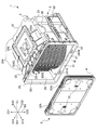
- FIG. 1 is an exploded perspective view showing a substrate storage container 1 according to the first embodiment of the present invention.
- FIG. 2 is an exploded perspective view showing a state in which the substrate W is stored in the substrate storage space 27 of the container body 2 of the substrate storage container 1 according to the present embodiment.
- FIG. 3 is a side perspective view showing the container body 2 of the substrate storage container 1 according to the first embodiment of the present invention.
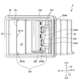
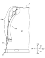
- FIG. 4A is a side sectional view showing the container body 2 of the substrate storage container 1 according to the first embodiment of the present invention.
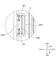
- FIG. 4B is a side enlarged sectional view showing the container body 2 of the substrate storage container 1 according to the first embodiment of the present invention.
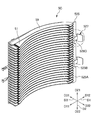
- FIG. 5A is a front perspective view showing the substrate support plate-like portion 5 of the substrate storage container 1 according to the first embodiment of the present invention.
- FIG. 5B is an enlarged front perspective view showing the substrate support plate-like portion 5 of the substrate storage container 1 according to the first embodiment of the present invention.
- FIG. 6A is a rear perspective view showing the substrate support plate-like portion 5 of the substrate storage container 1 according to the first embodiment of the present invention.
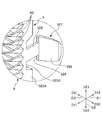
- FIG. 6B is an enlarged rear perspective view showing the substrate support plate-like portion 5 of the substrate storage container 1 according to the first embodiment of the present invention.
- FIG. 6C is a plan view showing the substrate support plate portion 5 of the substrate storage container 1 according to the first embodiment of the present invention.
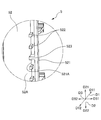
- FIG. 6D is an enlarged plan view showing the substrate support plate-like portion 5 of the substrate storage container 1 according to the first embodiment of the present invention.
- FIG. 7 is a side perspective view showing a state where the substrate support plate-like portion 5 is fixed to the first side wall 25 of the container body 2 of the substrate storage container 1 according to the first embodiment of the present invention.
- FIG. 8A is a plan cross-sectional view of the main part showing a state in which the substrate support plate-like portion 5 is fixed to the container body 2 of the substrate storage container 1 according to the first embodiment of the present invention.
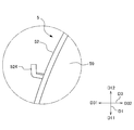
- FIG. 8B is an enlarged plan sectional view showing a state in which the substrate support plate-like portion 5 is fixed to the container body 2 of the substrate storage container 1 according to the first embodiment of the present invention.
- a direction (lower left direction in FIG. 1) from the container body 2 to the lid 3 described later is defined as a front direction D11, and the opposite direction is defined as a rear direction D12. It is defined as D1.
- a direction (upward direction in FIG. 1) from the lower wall 24 to the upper wall 23, which will be described later, is defined as an upward direction D21
- the opposite direction is defined as a downward direction D22, and these are defined as a vertical direction D2.
- a direction (upper left direction in FIG. 1) from the second side wall 26 to be described later to the first side wall 25 is defined as the left direction D31
- the opposite direction is defined as the right direction D32, and these are defined as the left and right direction D3.
- the substrate W (see FIG. 2) stored in the substrate storage container 1 is a disk-shaped silicon wafer, glass wafer, sapphire wafer, or the like, and is a thin one used in the industry.
- the substrate W in this embodiment is a silicon wafer having a diameter of 450 mm.
- the substrate storage container 1 has a container body 2, a lid 3, and a substrate support plate-like portion 5 as a side substrate support portion.
- the container body 2 has a cylindrical wall portion 20 in which a container body opening 21 is formed at one end and the other end is closed.
- a substrate storage space 27 is formed in the container body 2.
- the substrate storage space 27 is formed so as to be surrounded by the wall portion 20.
- the substrate support plate-shaped portion 5 is disposed in a portion of the wall portion 20 that forms the substrate storage space 27. As shown in FIG. 2, a plurality of substrates W can be stored in the substrate storage space 27.
- the substrate support plate-like portion 5 is provided on the wall portion 20 so as to form a pair in the left-right direction D3 in the substrate storage space 27.
- the substrate support plate-like portion 5 is arranged in such a manner that adjacent substrates W are separated from each other at a predetermined interval and arranged in parallel.
- the part can be supported.
- a back side substrate support portion 6 (see FIG. 7 and the like) is provided on the back side of the substrate support plate-like portion 5.
- the back-side substrate support 6 can support the rear portions of the edges of the plurality of substrates W when the container body opening 21 is closed by the lid 3.
- the lid 3 is detachable from the container main body opening 21 and can close the container main body opening 21.
- a portion of the lid 3 that faces the substrate storage space 27 when the container main body opening 21 is closed by the lid 3 (the surface on the back side of the lid 3 shown in FIG. 1) has a front retainer. (Not shown) is provided.
- the front retainer (not shown) is arranged to make a pair with the back side substrate support 6.
- the front retainer (not shown) can support the front portions of the edges of the plurality of substrates W when the container body opening 21 is closed by the lid 3.
- the front retainer (not shown) supports adjacent substrates by supporting the plurality of substrates W in cooperation with the back substrate support 6 when the container body opening 21 is closed by the lid 3.
- a plurality of substrates W are held in a state where the Ws are separated from each other at a predetermined interval and are arranged in parallel.
- a handling member 8 is disposed on a pair of side walls 25 and 26, which will be described later, constituting the wall portion 20 so as to face the outer surfaces of the side walls 25 and 26, respectively.
- the lower part of the rib 82 of the handling member 8 is supported by a fork of a forklift (not shown), whereby the substrate storage container 1 can be lifted by the forklift.
- a forklift not shown
- the wall portion 20 of the container body 2 includes a back wall 22, an upper wall 23, a lower wall 24, a first side wall 25, and a second side wall 26.
- the back wall 22, the upper wall 23, the lower wall 24, the first side wall 25, and the second side wall 26 are made of a plastic material or the like. In the first embodiment, they are integrally formed of polycarbonate.
- the first side wall 25 and the second side wall 26 face each other, and the upper wall 23 and the lower wall 24 face each other.
- the rear end of the upper wall 23, the rear end of the lower wall 24, the rear end of the first side wall 25, and the rear end of the second side wall 26 are all connected to the back wall 22.
- the front end of the upper wall 23, the front end of the lower wall 24, the front end of the first side wall 25, and the front end of the second side wall 26 have a positional relationship facing the back wall 22 and have a substantially rectangular shape. Opening peripheral edge portion 28 is formed.
- the opening peripheral edge 28 is provided at one end of the container main body 2, and the back wall 22 is located at the other end of the container main body 2.
- the outer shape of the container body 2 formed by the outer surface of the wall portion 20 is box-shaped.
- the inner surface of the wall portion 20, that is, the inner surface of the back wall 22, the inner surface of the upper wall 23, the inner surface of the lower wall 24, the inner surface of the first side wall 25, and the inner surface of the second side wall 26 are surrounded by these. 27 is formed.
- the container main body opening 21 formed in the opening peripheral edge portion 28 is surrounded by the wall portion 20 and communicates with the substrate storage space 27 formed in the container main body 2.
- a maximum of 25 substrates W can be stored in the substrate storage space 27 in such a positional relationship that the upper and lower surfaces of the substrate W are substantially horizontal.
- latch engaging recesses 231 ⁇ / b> A and 231 ⁇ / b> B that are recessed toward the outside of the substrate storage space 27 in the portions of the upper wall 23 and the lower wall 24 and in the vicinity of the opening peripheral edge portion 28.
- 241A, 241B are formed.
- a total of four latch engaging recesses 231A, 231B, 241A, 241B are formed near the left and right ends of the upper wall 23 and the lower wall 24, one each.
- a flange fixing portion (not shown) and ribs 235 ⁇ / b> A and 235 ⁇ / b> B are provided integrally with the upper wall 23 on the outer surface of the upper wall 23.
- a flange fixing portion (not shown) is disposed at the center of the upper wall 23.
- a top flange 236 is fixed to a flange fixing portion (not shown).
- the top flange 236 is disposed at the center of the upper wall 23.
- the top flange 236 is hung on an arm (not shown) of these machines as a lifting member when the substrate storage container 1 is suspended in an AMHS (automatic wafer transfer system), PGV (wafer substrate transfer carriage) or the like. Thereby, the substrate storage container 1 is suspended from the arm.
- AMHS automated wafer transfer system
- PGV wafer substrate transfer carriage
- a plurality of ribs 235A extend from the top flange 236 in the left front direction and the right front direction, respectively. Further, a plurality of ribs 235B extend from the top flange 236 in the front direction D11, and a plurality of ribs 235B extend from the top flange 236 in the rear direction D12.
- the first side wall 25 has a symmetrical shape with the second side wall 26, only the first side wall 25 will be described below, and description of the second side wall 26 will be omitted.
- the first side wall 25 has a back outer surface depression 254.
- the 1st side wall 25 has the groove
- the rear outer surface depression 254 gradually decreases the distance between the first side wall 25 and the side wall 26 in the left-right direction D3 from the opening peripheral edge 28 toward the rear direction D12. As shown in FIG. 1 and FIG. 8A, the rear outer surface depression 254 gradually decreases the distance between the first side wall 25 and the side wall 26 in the left-right direction D3 from the opening peripheral edge 28 toward the rear direction D12. As shown in FIG. 1 and FIG. 8A, the rear outer surface depression 254 gradually decreases the distance between the first side wall 25 and the side wall 26 in the left-right direction D3 from the opening peripheral edge 28 toward the rear direction D12. As shown in FIG.
- the portion of the back outer surface depression 254 on the back side (rear side) of the first side wall 25 is a disk-shaped substrate W (see FIG. 1) stored in the substrate storage space 27 (see FIG. 1). 2), the outer surfaces of the pair of side walls 25 and 26 are stepped, and the step in the left-right direction D3 is larger than the portion of the rear outer surface depression 254 on the front side of the first side wall 25. It is configured.
- the inner surface of the rear outer surface recess 254 also has a stepped shape, similar to the outer surface of the rear outer surface recess 254.
- the groove fitting rib portion 251 is a portion of the inner surface of the first side wall 25, and is about one third of the depth of the container body 2 in the front-rear direction, and is rearward from the opening peripheral portion 28. It exists in the part which went to D12. In this portion, there is a step portion 254G (FIG. 3 and the like) located in the foremost direction D11 of the step-like back outer surface depression 254.
- the groove fitting rib portion 251 is a portion of the inner surface of the first side wall 25 and protrudes forward from a portion entering the inside of the stepped portion 254G, and extends linearly in the vertical direction D2. I'm out.
- the groove fitting rib portion 251 can be fitted into a groove 521A described later.
- a positioning groove 251A as a positioning portion is formed at the center of the groove fitting rib portion 251 in the vertical direction D2.
- the positioning groove 251A is formed so as to be cut out from the front end which is the protruding end of the groove fitting rib portion 251 in the rear direction D12, and can be engaged with an alignment rib 523 which will be described later as a positioned portion. .
- the front convex portion 252 is a part of a step-like back outer surface depression 254 and is a first step portion 254B (a wall surface substantially parallel to the back wall 22 from the back wall 22). It exists in the inner surface of the part (refer FIG. 8B) which has.
- a total of three front convex portions 252 are provided in the vicinity of the upper end portion, in the vicinity of the lower end portion, and in the central portion in the vertical direction D2 of the rear outer surface depression 254.
- the front convex portion 252 has a U-shape that is long in the vertical direction D2 in a front view, and protrudes in the front direction D11.
- a square-shaped frame portion 525 ⁇ / b> C as an end engaging portion of the support wall 52 described later can be engaged with the front convex portion 252.
- the connecting portion between the first step portion 254B (see FIG. 8B) and the portion 254A from the back wall 22 toward the first step portion 254B is outward of the container body 2. It has the outward protrusion part 254H which protrudes.
- the inner surface of the outward projecting portion 254H forms a concave portion that is recessed outward of the container body 2.
- the outward projecting portions 254H are formed in pairs in the vertical direction D2.
- the outward projecting portion 254H has a position between the upper front convex portion 252 and the central front convex portion 252 of the three front convex portions 252, and the lower front convex portion 252 and the center in the vertical direction D2. It exists in the position between the front convex parts 252.
- a pair of narrow passage forming walls 253 exist in each outward projecting portion 254H.
- the narrow passage forming wall 253 extends from the inner surface of the outer protruding portion 254H to the substrate storage space 27 so as to block the upper third and the lower third of the front of the outer protruding portion 254H in the vertical direction. It protrudes inward (rightward direction D32).
- a portion between the pair of narrow passage forming walls 253 forms a narrow passage 253A.
- the space 253B formed by the inner surface of the outward projecting portion 254H communicates with a portion of the substrate storage space 27 and in front of the narrow passage forming wall 253 through the narrow passage 253A in the front direction D11. .
- the space 253B is not particularly obstructed in the inward direction (right direction D32) of the substrate storage space 27, and is a portion of the substrate storage space 27 that communicates with portions other than the space 253B. ing.
- the substrate support plate-like portions 5 are provided in the first side wall 25 and the second side wall 26, respectively, and are arranged in the substrate storage space 27 so as to form a pair in the left-right direction D3.
- the substrate support plate-like portion 5 includes a plate portion 51 and a support wall 52 as a plate portion support portion.
- the plate portion 51 and the support wall 52 are formed by integrally molding resin, whereby the plate portion 51 is supported by the support wall 52.
- the plate portion 51 has a plate-like substantially arc shape.
- a total of 50 plate portions 51 are provided on each of the first side wall 25 and the second side wall 26, 25 in the vertical direction D2.
- Adjacent plate portions 51 are arranged in parallel with each other in the vertical direction D2 so as to be spaced apart from each other at an interval of 10 mm to 12 mm.
- a plate-like member 59 is disposed above the uppermost plate portion 51 in parallel with the other plate portion 51, and this is located at the uppermost position in the substrate storage space 27. It is a member that serves as a guide for the insertion of the substrate W to be inserted into the substrate.
- the 25 plate portions 51 provided on the first side wall 25 and the 25 plate portions 51 provided on the second side wall 26 have a positional relationship facing each other in the left-right direction D3.
- the 50 plate portions 51 and the member 59 serving as a plate-shaped guide parallel to the plate portion 51 have a positional relationship parallel to the inner surface of the lower wall 24.
- a convex portion 511 is provided on the upper surface of the plate portion 51.
- substrate W supported by the board part 51 contacts only the protrusion end of the convex part 511, and does not contact the board part 51 by a surface.
- the support wall 52 is configured by a plate-like support wall 52 extending in the vertical direction D2 and the substantially front-back direction D1. As shown in FIGS. 6A to 6C, the support wall 52 is connected to the side edge of the plate portion 51 from one end portion to the other end portion in the longitudinal direction of the plate portion 51. The plate-like support wall 52 is curved toward the substrate storage space 27 along the outer edge of the plate portion 51.
- the 25 plate portions 51 provided on the first side wall 25 are connected to a support wall 52 provided on the first side wall 25 side.
- the 25 plate portions 51 provided on the second side wall 26 are connected to a support wall 52 provided on the second side wall 26 side.
- the support wall 52 is fixed to the first side wall 25 and the second side wall 26, respectively.
- the support wall 52 includes a groove forming portion 521, a protrusion 522, an alignment rib 523 as a positioned portion, a straight rib 524, an end surface 525A, and a locked portion as a back side locked portion. A part extending part 526 and a locked plate part 527.
- the groove forming portion 521 is present in the portion (opening side portion) of the support wall 52 on the container body opening 21 side. More specifically, the opening side portion means the vicinity of the front end portion of the support wall 52, and the groove forming portion 521 exists in the vicinity of the front end portion of the support wall 52.
- the groove forming portion 521 has a substantially L shape extending in the right direction, bent at a right angle, and extending rearward in plan view.
- a groove 521A that opens toward the rear direction D12 is formed by the groove forming portion 521 and the outer surface 52A of the support wall 52.
- the groove 521A extends linearly over the entire 25 plate portions 51 in the direction intersecting the plurality of plate portions 51, specifically, in the vertical direction D2.
- the groove 521A is divided into an upper side and a lower side in the vertical direction D2, two protrusions 522 are respectively provided on the upper side, the lower side, and the upper side, the middle part, and the lower side of the groove 521A. It exists at intervals.
- the protrusion 522 protrudes from the outer surface 52A of the support wall 52 forming the groove 521A to the outside of the substrate storage space 27 (left direction D31). Accordingly, the protrusion 522 has a predetermined width by narrowing the width of the groove 521A in the direction orthogonal to the extending direction of the groove 521A, that is, in the left-right direction D3.
- the alignment rib 523 is formed at the center of the groove 521A in the vertical direction D2, which is the direction in which the groove 521A extends.
- the alignment rib 523 extends from the groove forming portion 521 to the outer surface 52A of the support wall 52, and is formed so as to divide the groove 521A into an upper portion and a lower portion.
- the width of the alignment rib 523 in the vertical direction D2 is equal to or smaller than the width of the positioning groove 251A in the same direction. Therefore, the alignment rib 523 can be inserted into the positioning groove 251A, and the positioning groove 251A locks the alignment rib 523 by this insertion.
- the linear rib 524 is on the outer surface 52A of the support wall 52 and is located at a substantially central position in the front-rear direction D1. As shown in FIGS. 6C and 6D, the linear rib 524 has a substantially L-shape extending outward from the substrate storage space 27, bent at a right angle, and extending rearward in plan view. The straight ribs 524 have a positional relationship parallel to the grooves 521A (FIG. 6A) and extend in the up-down direction, and face each other over substantially the entire groove 521A.
- the end of the back side of the support wall 52 that is, the end in the rear direction D 12 of the support wall 52 has an end wall 525.
- the end wall 525 has a plate shape having a positional relationship parallel to the front-rear direction D1 and the up-down direction D2.
- the end wall 525 has an end surface 525 ⁇ / b> A that is a surface of the end wall 525 on the inner side of the substrate storage space 27.
- the end surface 525A is a flat surface parallel to the front-rear direction D1 that is the direction connecting the back wall 22 and the container body opening 21 and the vertical direction D2 that is the direction connecting the upper wall 23 and the lower wall 24. It is configured.
- the end wall 525 is formed with recesses 525B recessed in the front direction D11 at two upper and lower portions, and the locked portion extension portion 526 exists in the recess 525B. is doing.
- the locked portion extending portion 526 is integrally formed and connected to the portion of the end wall 525 that forms the concave portion 525B.
- the locked portion extending portion 526 has a positional relationship parallel to the end wall 525, and from the portion of the end wall 525 constituting the recess 525B, the rear direction D12 that is the direction in which the groove 521A opens. It extends to.
- the locked portion extending portion 526 can be elastically deformed so as to swing in the normal direction (left-right direction D3) of the end surface 525A.
- the width of the locked portion extending portion 526 in the vertical direction D2 is smaller than the width of the narrow passage 253A (see FIG. 4B) between the paired narrow passage forming walls 253. Therefore, the locked portion extending portion 526 can be inserted into the narrow passage 253A.
- the locked portion extension portion 526 does not protrude inward (rightward direction D32) of the substrate storage space 27 from the end surface 525A.
- the inner side surface of the substrate storage space 27 of the locked portion extension portion 526 (the right end surface of the locked portion extension portion 526 in FIG. 8B) is in a positional relationship (equal plane) with the end surface 525A. Position relationship).
- the locked plate portion 527 is integrally formed and connected to the extended end portion of the locked portion extending portion 526.
- the locked plate portion 527 slightly extends from the extended end portion of the locked portion extending portion 526 in the extending direction of the locked portion extending portion 526 (rear direction D12). It bends inwardly and extends, and further bends in the backward direction D12 and slightly extends.
- the locked plate portion 527 is formed wider than the locked portion extending portion 526 in the vertical direction D2, which is the direction in which the groove 521A extends.
- variety of the to-be-latched board part 527 in the up-down direction D2 is larger than the width
- the wide plate-like portion 528 of the locked plate portion 527 has a substantially trapezoidal substantially plate shape as a whole, and the width of the locked plate portion 527 in the vertical direction D2 is the width of the locked plate portion 527. It is small so that the locked plate portion 527 is slightly tapered in the direction in which the plate-like portion 528 extends.
- the upper and lower portions of the portion of the locked plate portion 527 connected to the extended end portion of the locked portion extending portion 526, that is, the front end of the locked plate portion 527 is in engagement contact. It has a surface 529.
- the engagement contact surface 529 has a positional relationship parallel to the vertical direction D2 and the horizontal direction D3.
- the engagement contact surface 529 is narrow when the support wall 52 is fixed to the first side wall 25 by the locked plate portion 527 being locked to the narrow passage forming wall 253.
- the surface abuts against the surface 253C on the rear direction D12 side of the passage forming wall 253.
- the engagement contact surface 529 does not protrude inward of the substrate storage space 27 from the end surface 525A and is positioned outward of the substrate storage space 27 from the end surface 525A. is doing.
- FIG. 6A at the rear end of the end wall 525, there are three square-shaped frame portions 525C each having a rectangular through hole.
- the three square-shaped frame portions 525C are positioned at equal intervals in the vertical direction D2, and the through-holes of the square-shaped frame portion 525C open in the front-rear direction D1.
- Front convex portions 252 (see FIG. 3 and the like) can be inserted into the through holes of the B-shaped frame portion 525C.
- the substrate support plate-like portion 5 having the above-described configuration is fixed to the first side wall 25 and the second side wall 26, and the substrate support plate-like portion 5 allows adjacent substrates W among the plurality of substrates W to be arranged in a predetermined manner.
- the edges of the plurality of substrates W can be supported in a state of being spaced apart from each other and being in a parallel positional relationship.
- the back substrate support 6 has a wall substrate support 60 as shown in FIG. 5B.
- the wall portion substrate support portion 60 is formed integrally with the plate portion 51 and the support wall 52 at the rear end portion of the plate portion 51 and the support wall 52 of the substrate support plate-like portion 5.
- the back substrate support 6 is separate from the substrate support plate-like portion 5, that is, the wall substrate support 60 is separate from the plate portion 51 and the support wall 52 of the substrate support plate-like portion 5. It may be configured.
- the wall portion substrate support portions 60 are provided in a number corresponding to each of the substrates W that can be stored in the substrate storage space 27, specifically, 25 pieces.
- substrate support part 60 provided in the 1st side wall 25 and the 2nd side wall 26 has the positional relationship which makes a pair with the front retainer (not shown) mentioned later in the front-back direction D1.
- the wall portion substrate support portion 60 holds the edge of the edge portion of the substrate W.
- the lid 3 has a substantially rectangular shape that substantially matches the shape of the opening peripheral edge 28 of the container body 2.
- the lid 3 can be attached to and detached from the opening peripheral edge 28 of the container main body 2, and the lid 3 can close the container main body opening 21 by attaching the lid 3 to the opening peripheral edge 28.
- It is the inner surface of the lid 3 (the surface on the back side of the lid 3 shown in FIG. 1), at the position in the rearward direction D12 of the opening peripheral edge 28 when the lid 3 closes the container main body opening 21.
- An annular seal member 4 is attached to the surface facing the formed stepped portion surface (seal surface 281).
- the sealing member 4 is made of elastically deformable POE (polyoxyethylene), PEE, various thermoplastic elastomers such as polyester and polyolefin, fluororubber, silicon rubber, and the like.
- the seal member 4 is arranged so as to go around the outer peripheral edge of the lid 3.
- the seal member 4 When the lid 3 is attached to the opening peripheral edge 28, the seal member 4 is sandwiched between the seal surface 281 and the inner surface of the lid 3 and elastically deformed, and the lid 3 seals the container main body opening 21. Shuts down in a closed state. By removing the lid 3 from the opening peripheral edge 28, the substrate W can be taken into and out of the substrate storage space 27 in the container body 2.
- the lid 3 is provided with a latch mechanism.
- the latch mechanism is provided in the vicinity of both left and right end portions of the lid 3, and as shown in FIG. 1, the two upper latch portions 32 ⁇ / b> A that can project in the upward direction D ⁇ b> 21 from the upper side of the lid 3, And two lower latch portions (not shown) that can project in the downward direction D22 from the lower side.
- the two upper latch portions 32 ⁇ / b> A are disposed in the vicinity of the left and right ends of the upper side of the lid 3, and the two lower latch portions are disposed in the vicinity of the left and right ends of the lower side of the lid 3.
- An operation unit 33 is provided on the outer surface of the lid 3.
- the upper latch portion 32A and the lower latch portion (not shown) can be protruded from the upper and lower sides of the lid 3, and from the upper and lower sides. It can be made the state which does not project.
- the upper latch portion 32A protrudes from the upper side of the lid body 3 in the upward direction D21 and engages with the latch engagement recesses 231A and 231B of the container body 2, and the lower latch portion extends from the lower side of the lid body 3 in the downward direction D22.
- the lid 3 is fixed to the opening peripheral edge 28 of the container body 2 by projecting to the latch engagement recesses 241A and 241B of the container body 2.
- a recess (not shown) that is recessed outward from the substrate storage space 27 is formed inside the lid 3.
- a front retainer (not shown) is fixedly provided on the concave portion (not shown) and the lid 3 outside the concave portion.
- the front retainer has a front retainer substrate receiving portion (not shown). Two front retainer substrate receiving portions are arranged so as to form a pair spaced apart at a predetermined interval in the left-right direction D3. The front retainer substrate receiving portions arranged in pairs so as to form a pair in this way are provided in a state where 25 pairs are juxtaposed in the vertical direction D2. When the substrate W is stored in the substrate storage space 27 and the lid 3 is closed, the front retainer substrate receiving portion sandwiches and supports the edge of the edge of the substrate W.
- the substrate support plate-like portion 5 is attached to and detached from the first side wall 25 as follows.
- the alignment rib 523 (see FIG. 6B) is inserted into the positioning groove 251A (see FIG. 3), and the groove 521A (see FIG. 6B).
- the front convex portion 252 (see FIG. 3) can be inserted into the through hole of the square frame 525C (see FIG. 6A).
- the front convex portion 252 is disposed close to the through hole of the letter-shaped frame portion 525C.
- the rear portion of the support wall 52 is first deformed while being elastically deformed so that the locked portion extending portion 526 (see FIG. 5B) is curved inwardly of the substrate storage space 27 (right direction D32 in FIG. 8B). It pushes to left direction D31 so that the side wall 25 may be approached.
- the edge of the engagement contact surface 529 gets over the edge of the narrow passage forming wall 253 in the extending direction. Then, when the locked plate portion 527 is locked to the narrow passage forming wall 253, that is, the back side portion which is the portion of the support wall 52 on the back wall side is locked to the back side locking portion. As a result, the support wall 52 is fixed to the first side wall 25. At this time, as shown in FIG. 8B, the engagement contact surface 529 is in surface contact with the surface 253C on the rear direction D12 side of the narrow passage forming wall 253. Further, the locked portion extending portion 526 is inserted into the narrow passage 253A. Further, the front convex portion 252 (see FIG. 3) is inserted into the through hole of the square frame portion 525C (see FIG. 6A).
- the locked portion extending portion 526 (see FIG. 8B) is bent inward of the substrate storage space 27 (right direction D32 in FIG. 8B). In this manner, the rear portion of the support wall 52 is drawn toward the inside of the substrate storage space 27 while being elastically deformed. Thereby, the end edge of the engagement contact surface 529 gets over the end edge in the extending direction of the narrow passage forming wall 253. As a result, the locked plate portion 527 is detached from the narrow passage forming wall 253, that is, the back wall side support wall 52 portion (back side portion) is separated from the narrow passage forming wall 253 as the back side locking portion. By releasing, the support wall 52 is released from being fixed to the first side wall 25.
- the front convex portion 252 is detached from the through hole of the square-shaped frame portion 525C.
- substrate support plate-shaped part 5 is removed from the 1st side wall 25 by removing the groove fitting rib part 251 from the groove
- the support wall 52 has the groove forming portion 521 in which the groove 521 ⁇ / b> A extending linearly throughout the plurality of plate portions 51 in the direction intersecting the plurality of plate portions 51 is formed.
- On the inner surface there is a groove fitting rib portion 251 that extends linearly and can be fitted into the groove 521A.
- deformation due to molding contraction of the substrate support plate-like portion 5 as the side substrate support portion, for example, warpage can be corrected by following the groove fitting rib portion 251 of the container body 2 with little deformation.
- the assembly accuracy of the member that supports the substrate W can be improved.
- the support wall 52 has an alignment rib 523 as a positioned portion formed at the center of the groove 521A in the extending direction of the groove 521A, and the groove fitting rib in the extending direction of the groove fitting rib 251.
- a positioning groove 251 ⁇ / b> A as a positioning portion capable of locking the positioned portion is present at the center of the portion 251.
- the alignment ribs 523 are locked by the positioning groove 251A, so that the plurality of plate portions 51 at both ends of the groove 521A are fixed.
- the dimensional error in the pitch direction can be halved.
- the substrate support plate-like portion 5 has a protrusion 522 that is formed in the groove 521A and protrudes so as to narrow the width of the groove 521A in the direction orthogonal to the extending direction of the groove 521A. For this reason, the position of the board
- the groove forming portion 521 exists in the opening side portion that is the portion of the support wall 52 on the container body opening portion side, and the back side portion that is the portion of the support wall 52 on the back wall side is the back side locking portion. It has a back side locked part which can be locked. And the back side locked part is formed in the extended part of the to-be-locked part extending part 526 and the to-be-locked part extending part 526 which can be elastically deformed and extends in the opening direction of the groove 521A. And a locked plate portion 527 formed wider than the locked portion extending portion 526 in the extending direction of 521A. Further, the back side locking portion of the first side wall 25 is a narrow passage forming wall 253 that forms a narrow passage 253A in which the locked portion extending portion 526 can be inserted but the locked plate portion 527 cannot be inserted. Have
- the locked plate portion 527 can be locked to the narrow passage forming wall 253. And by being locked in this way, the portion of the support wall 52 on the back wall side is locked to the back side locking portion. Therefore, the support wall 52 can be locked to the first side wall 25 at the back side and the opening side portion of the support wall 52.
- the locked portion extending portion 526 does not protrude inward of the substrate storage space 27 from the end surface 525A and has a positional relationship that coincides with the end surface 525A. Even when the substrate support plate-like portion 5 is pulled in the direction from the back side to the opening side (the forward direction D11), which is the direction in which the first plate 25 is removed from the first side wall 25, the locked plate portion 527 is narrowed. It is possible to make it difficult to move the locked plate portion 527 to the inside of the substrate storage space 27 in the direction in which the locking to the passage forming wall 253 is released. As a result, it is possible to make it difficult for the substrate support plate-like portion 5 as the side substrate support portion to be detached from the first side wall 25.
- the locked plate portion 527 has an engagement contact surface 529 that can contact the narrow passage forming wall 253 when locked to the narrow passage forming wall 253, the locked plate portion 527 is also provided. Can be stably locked to the narrow passage forming wall 253.
- the engagement contact surface 529 does not protrude inward of the substrate storage space 27 from the end surface 525A, but is positioned outward of the substrate storage space 27 from the end surface 525A. For this reason, even when the substrate support plate-like portion 5 is pulled in the direction (front direction D11) from the back side toward the opening side, which is the direction in which the substrate support plate-like portion 5 is removed from the first side wall 25. Thus, it is possible to make it difficult to move the locked plate portion 527 to the inside of the substrate storage space 27 in the direction in which the locking of the locked plate portion 527 to the narrow passage forming wall 253 is released. As a result, it is possible to make it difficult for the substrate support plate-like portion 5 as the side substrate support portion to be detached from the first side wall 25.
- linear ribs 524 having a positional relationship parallel to the groove 521A are present on the support wall 52 so as to face almost the entire groove 521A. For this reason, the intensity
- FIG. 9A is a front perspective view showing a substrate support plate-like portion 5B of the substrate storage container according to the second embodiment of the present invention.
- FIG. 9B is an enlarged front perspective view showing the substrate support plate-like portion 5B of the substrate storage container according to the second embodiment of the present invention.
- FIG. 9C is a plan sectional view showing a substrate support plate-like portion 5B of the substrate storage container according to the second embodiment of the present invention.
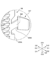
- FIG. 9D is an enlarged plan cross-sectional view showing the locked portion extending portion 526 and the locked plate portion 527 of the substrate supporting plate-like portion 5B of the substrate storage container according to the second embodiment of the present invention.
- FIG. 10A is a cross-sectional plan view of a principal part showing a state in which the substrate support plate-like portion 5B is fixed to the container body 2 of the substrate storage container according to the second embodiment of the present invention.
- FIG. 10B is a plan enlarged sectional view showing a state where the substrate support plate-like portion 5B is fixed to the container body 2 of the substrate storage container according to the second embodiment of the present invention.
- the substrate storage container according to the second embodiment differs from the substrate storage container 1 according to the first embodiment in that the direction of the engagement contact surface 529B of the substrate support plate-like portion 5B is different.
- the same components as those in the first embodiment are denoted by the same reference numerals and description thereof is omitted.
- the engagement contact surface 529B is a flat slope (to the container main body opening 21 as it goes inward (right direction D32) of the substrate storage space 27). A flat slope toward the front direction D11). Therefore, the engagement contact surface 529B contacts the surface 253C on the rear direction D12 side of the narrow passage forming wall 253 on the inner edge (the edge on the right direction D32 side) of the substrate storage space 27. Only.
- the engagement contact surface 529 ⁇ / b> B is configured by a slope toward the container body opening as it goes inward of the substrate storage space 27. For this reason, even when the substrate support plate-like portion 5 is pulled in the direction from the back side toward the opening side (front direction D11), which is the direction in which the substrate support plate-like portion 5 is removed from the first side wall 25.
- the locked plate portion 527 can be made extremely difficult to move inward of the substrate storage space 27 in the direction in which the locked plate portion 527 is unlocked from the narrow passage forming wall 253. As a result, the substrate support plate-like portion 5 as the side substrate support portion can be made extremely difficult to come off from the first side wall 25.
- FIG. 11A is a front perspective view showing a substrate support plate-like portion 5C of the substrate storage container 1 according to the third embodiment of the present invention.
- FIG. 11B is an enlarged front perspective view showing the substrate support plate-like portion 5C of the substrate storage container 1 according to the third embodiment of the present invention.
- FIG. 11C is a plan sectional view showing a substrate support plate-like portion 5C of the substrate storage container 1 according to the third embodiment of the present invention.
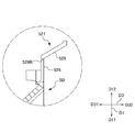
- FIG. 11D is an enlarged plan sectional view showing the locked portion extending portion 526C and the locked plate portion 527 of the substrate supporting plate-like portion 5C of the substrate storage container 1 according to the third embodiment of the present invention.
- the locked portion extending portion 526C of the substrate support plate-like portion 5C is located outward (left direction D31) of the substrate storage space 27 from the end surface 525A.
- it differs from the substrate storage container 1 according to the first embodiment.
- the same components as those in the first embodiment are denoted by the same reference numerals and description thereof is omitted.
- the locked portion extending portion 526C is a portion of the end wall 525 constituting the recess 525B, and is more outward of the substrate storage space 27 than the end surface 525A. It is integrally formed and connected to the part (left direction D31).
- the locked portion extending portion 526C extends from the portion of the end wall 525 constituting the concave portion 525B in the rear direction D12 that is the direction in which the groove 521A opens. Accordingly, as shown in FIG. 11D and the like, the locked portion extending portion 526C does not protrude inward of the substrate storage space 27 from the end surface 525A, and is closer to the substrate storage space 27 than the end surface 525A. It is located outward (left direction D31).
- the extended end portion of the locked portion extending portion 526C is integrally formed and connected to the wide portion 528 of the locked plate portion 527 and the frontmost portion of the wide portion 528. Has been.
- the locked portion extending portion 526C does not protrude inward of the substrate storage space 27 from the end surface 525A, and is positioned outward of the substrate storage space 27 from the end surface 525A. For this reason, even when the substrate support plate-like portion 5 is pulled in the direction (front direction D11) from the back side toward the opening side, which is the direction in which the substrate support plate-like portion 5 is removed from the first side wall 25.
- the locked plate portion 527 can be made extremely difficult to move inward of the substrate storage space 27 in the direction in which the locked plate portion 527 is unlocked from the narrow passage forming wall 253.
- the substrate support plate-like portion 5 ⁇ / b> C as the side substrate support portion can be made extremely difficult to come off from the first side wall 25.
- the shape and configuration of the substrate storage container 1 are not limited to the shape and configuration of the above-described embodiment.
- the engagement contact surface 529 is located outward of the substrate storage space 27 from the end surface 525A, but is not limited thereto.
- the engagement contact surface may have a positional relationship that coincides with the end surface 525A without projecting inward of the substrate storage space 27 from the end surface 525A.
- Substrate storage container 2
- Container body 3 Lid 5
- Substrate support plate-like part (side board support part) 20
- Wall portion 21 Container body opening portion 22
- Back wall 23 Upper wall 24
- Lower wall 25
- First side wall 26 Second side wall 27
- Substrate storage space 51
- Plate portion 52 Support wall (plate portion support portion) 251
- Positioning groove (positioning portion) 253
- 253A Narrow passage 521
- Groove forming portion 521A Groove 522
- Alignment rib (positioned portion) 524 Linear rib 525C
- B-shaped frame part (end engaging part) 526 Locked portion extending portion 527 Locked plate portion 529 Engagement contact surface
- W Substrate
Landscapes
- Container, Conveyance, Adherence, Positioning, Of Wafer (AREA)
- Packaging Frangible Articles (AREA)
Abstract
Description
2 容器本体
3 蓋体
5 基板支持板状部(側方基板支持部)
20 壁部
21 容器本体開口部
22 奥壁
23 上壁
24 下壁
25 第1側壁
26 第2側壁
27 基板収納空間
51 板部
52 支持壁(板部支持部)
251 溝嵌合リブ部
251A 位置決め溝(位置決め部)
253 狭通路形成壁(奥側係止部)
253A 狭い通路
521 溝形成部
521A 溝
522 突起
523 位置合せリブ(被位置決め部)
524 直線状のリブ
525C ロの字状枠部(端部係合部)
526 被係止部延出部
527 被係止板部
529 係合当接面
W 基板
Claims (8)
- 一端部に容器本体開口部が形成され他端部が閉塞された筒状の壁部であって、奥壁、上壁、下壁、及び一対の側壁を有し前記上壁の一端部、前記下壁の一端部、及び前記側壁の一端部によって前記容器本体開口部が形成された壁部を備え、前記上壁の内面、前記下壁の内面、前記側壁の内面、及び前記奥壁の内面によって、複数の基板を収納可能であり前記容器本体開口部に連通する基板収納空間が形成された容器本体と、
前記容器本体開口部に対して着脱可能であり、前記容器本体開口部を閉塞可能な蓋体と、
前記基板収納空間内において対をなすように前記一対の側壁にそれぞれ固定されて配置され、前記蓋体によって前記容器本体開口部が閉塞されていないときに、前記複数の基板のうちの隣接する基板同士を所定の間隔で離間させて並列させた状態で、前記複数の基板の縁部を支持可能な側方基板支持部と、を備え、
前記側方基板支持部は、平行な位置関係を有して前記複数の基板の縁部を支持する複数の板部と、前記板部を支持すると共に前記側壁に固定される板部支持部とを有し、前記板部支持部は、前記複数の板部に交差する方向へ前記複数の板部の全体にわたって直線状に延びる溝が形成された溝形成部と、前記溝内に形成され前記溝の延びる方向に直交する方向における前記溝の幅を狭めるように突出する突起と、前記溝の延びる方向における前記溝の中央部に形成された被位置決め部とを有し、
前記側壁の内面には、前記溝に嵌合可能な直線状に延出する溝嵌合リブ部が存在し、前記溝嵌合リブ部の延出方向における前記溝嵌合リブ部の中央部には、前記被位置決め部を係止可能な位置決め部が存在する基板収納容器。 - 前記側壁の奥壁側の部分は、奥側係止部を有し、
前記板部支持部は、前記板部の長手方向における一端部から他端部にわたって前記板部の側端縁に接続された板状の支持壁により構成され、
前記溝形成部は、前記容器本体開口部側の前記支持壁の部分である開口側部に存在し、
前記奥壁側の前記支持壁の部分である奥側部は、前記奥側係止部に係止可能な奥側被係止部を有する請求項1に記載の基板収納容器。 - 前記板部支持部の前記奥側被係止部は、弾性変形可能であり前記溝の開口する方向に延びる被係止部延出部と、前記被係止部延出部の延出端部に形成され、前記溝の延びる方向に前記被係止部延出部よりも幅広に形成された被係止板部とを有し、
前記側壁の奥側係止部は、前記被係止部延出部を挿入可能であるが前記被係止板部を挿入不能とする狭い通路を形成する狭通路形成壁を有し、前記被係止部延出部が前記狭い通路に挿入されているときに、前記被係止板部は前記狭通路形成壁に係止される請求項2に記載の基板収納容器。 - 前記板部支持部の奥側部の端部は、前記奥壁と前記容器本体開口部とを結ぶ方向及び前記上壁と前記下壁とを結ぶ方向に平行な平坦な端部面を有し、
前記被係止部延出部は、前記端部面よりも前記基板収納空間の内方へ突出せずに、前記端部面と一致する位置関係を有するか、又は、前記端部面よりも前記基板収納空間の外方へ位置している請求項3に記載の基板収納容器。 - 前記被係止板部は、前記狭通路形成壁に係止されているときに、前記狭通路形成壁に当接可能な係合当接面を有する請求項3に記載の基板収納容器。
- 前記板部支持部の奥側部の端部は、前記奥壁と前記容器本体開口部とを結ぶ方向及び前記上壁と前記下壁とを結ぶ方向に平行な平坦な端部面を有し、
前記係合当接面は、前記端部面よりも前記基板収納空間の内方へ突出せずに、前記端部面と一致する位置関係を有するか、又は、前記端部面よりも前記基板収納空間の外方へ位置している請求項5に記載の基板収納容器。 - 前記係合当接面は、前記基板収納空間の内方へ向かうにつれて、前記容器本体開口部へ向かう斜面により構成されている請求項5又は請求項6に記載の基板収納容器。
- 前記支持壁には、前記溝と平行の位置関係を有する直線状のリブが前記溝の略全体にわたって対向して存在する請求項2~請求項7のいずれかに記載の基板収納容器。
Priority Applications (5)
| Application Number | Priority Date | Filing Date | Title |
|---|---|---|---|
| JP2015522422A JP6162803B2 (ja) | 2013-06-19 | 2013-06-19 | 基板収納容器 |
| KR1020157036100A KR102098790B1 (ko) | 2013-06-19 | 2013-06-19 | 기판수납용기 |
| PCT/JP2013/066890 WO2014203359A1 (ja) | 2013-06-19 | 2013-06-19 | 基板収納容器 |
| US14/898,358 US9960064B2 (en) | 2013-06-19 | 2013-06-19 | Substrate storing container |
| TW103120645A TWI628126B (zh) | 2013-06-19 | 2014-06-16 | 基板收納容器 |
Applications Claiming Priority (1)
| Application Number | Priority Date | Filing Date | Title |
|---|---|---|---|
| PCT/JP2013/066890 WO2014203359A1 (ja) | 2013-06-19 | 2013-06-19 | 基板収納容器 |
Publications (1)
| Publication Number | Publication Date |
|---|---|
| WO2014203359A1 true WO2014203359A1 (ja) | 2014-12-24 |
Family
ID=52104121
Family Applications (1)
| Application Number | Title | Priority Date | Filing Date |
|---|---|---|---|
| PCT/JP2013/066890 Ceased WO2014203359A1 (ja) | 2013-06-19 | 2013-06-19 | 基板収納容器 |
Country Status (5)
| Country | Link |
|---|---|
| US (1) | US9960064B2 (ja) |
| JP (1) | JP6162803B2 (ja) |
| KR (1) | KR102098790B1 (ja) |
| TW (1) | TWI628126B (ja) |
| WO (1) | WO2014203359A1 (ja) |
Cited By (3)
| Publication number | Priority date | Publication date | Assignee | Title |
|---|---|---|---|---|
| WO2017040707A1 (en) * | 2015-08-31 | 2017-03-09 | Entegris, Inc. | Front opening substrate container with compression latches |
| CN117326187A (zh) * | 2022-06-30 | 2024-01-02 | 家登精密工业股份有限公司 | 基板容器 |
| WO2024247263A1 (ja) * | 2023-06-02 | 2024-12-05 | ミライアル株式会社 | 基板収納容器 |
Families Citing this family (3)
| Publication number | Priority date | Publication date | Assignee | Title |
|---|---|---|---|---|
| SG11202003883RA (en) * | 2017-11-15 | 2020-05-28 | Shin Etsu Polymer Co Ltd | Substrate storage container |
| US11335576B2 (en) * | 2018-10-29 | 2022-05-17 | Miraial Co., Ltd. | Method for molding substrate storing container, mold, and substrate storing container |
| WO2023026485A1 (ja) | 2021-08-27 | 2023-03-02 | ミライアル株式会社 | 基板収納容器、その製造方法、及び蓋体側基板支持部 |
Citations (4)
| Publication number | Priority date | Publication date | Assignee | Title |
|---|---|---|---|---|
| JP2003200974A (ja) * | 2001-12-28 | 2003-07-15 | Sekisui Plastics Co Ltd | 緩衝材およびこれを用いた包装体 |
| JP2003300583A (ja) * | 2002-04-09 | 2003-10-21 | Sekisui Plastics Co Ltd | 板状体の搬送用箱 |
| WO2011148450A1 (ja) * | 2010-05-24 | 2011-12-01 | ミライアル株式会社 | 基板収納容器 |
| JP2012212766A (ja) * | 2011-03-31 | 2012-11-01 | Miraial Kk | ウエハ収納容器 |
Family Cites Families (6)
| Publication number | Priority date | Publication date | Assignee | Title |
|---|---|---|---|---|
| EP1004524B1 (en) | 1998-02-06 | 2014-12-31 | Sumco Corporation | Sheet support container |
| JP4146718B2 (ja) * | 2002-12-27 | 2008-09-10 | ミライアル株式会社 | 薄板支持容器 |
| US8365919B2 (en) * | 2005-12-29 | 2013-02-05 | Shin-Etsu Polymer Co., Ltd. | Substrate storage container |
| US8528738B2 (en) * | 2006-06-13 | 2013-09-10 | Entegris, Inc. | Reusable resilient cushion for wafer container |
| JP5270668B2 (ja) * | 2008-04-25 | 2013-08-21 | 信越ポリマー株式会社 | リテーナ、及びリテーナを備えた基板収納容器 |
| CN106941087B (zh) * | 2011-08-12 | 2020-03-10 | 恩特格里斯公司 | 晶片载具 |
-
2013
- 2013-06-19 KR KR1020157036100A patent/KR102098790B1/ko active Active
- 2013-06-19 JP JP2015522422A patent/JP6162803B2/ja active Active
- 2013-06-19 US US14/898,358 patent/US9960064B2/en active Active
- 2013-06-19 WO PCT/JP2013/066890 patent/WO2014203359A1/ja not_active Ceased
-
2014
- 2014-06-16 TW TW103120645A patent/TWI628126B/zh active
Patent Citations (4)
| Publication number | Priority date | Publication date | Assignee | Title |
|---|---|---|---|---|
| JP2003200974A (ja) * | 2001-12-28 | 2003-07-15 | Sekisui Plastics Co Ltd | 緩衝材およびこれを用いた包装体 |
| JP2003300583A (ja) * | 2002-04-09 | 2003-10-21 | Sekisui Plastics Co Ltd | 板状体の搬送用箱 |
| WO2011148450A1 (ja) * | 2010-05-24 | 2011-12-01 | ミライアル株式会社 | 基板収納容器 |
| JP2012212766A (ja) * | 2011-03-31 | 2012-11-01 | Miraial Kk | ウエハ収納容器 |
Cited By (7)
| Publication number | Priority date | Publication date | Assignee | Title |
|---|---|---|---|---|
| WO2017040707A1 (en) * | 2015-08-31 | 2017-03-09 | Entegris, Inc. | Front opening substrate container with compression latches |
| CN117326187A (zh) * | 2022-06-30 | 2024-01-02 | 家登精密工业股份有限公司 | 基板容器 |
| JP2024007413A (ja) * | 2022-06-30 | 2024-01-18 | 家登精密工業股▲ふん▼有限公司 | 基板収納容器とそのドアの組み立て部材、支持具組み立て部材及び弾性バッファ |
| JP2024007499A (ja) * | 2022-06-30 | 2024-01-18 | 家登精密工業股▲ふん▼有限公司 | 安定化用の支持体及びスムーズなトレイ連結を備えた基板容器 |
| JP7654032B2 (ja) | 2022-06-30 | 2025-03-31 | 家登精密工業股▲ふん▼有限公司 | 基板収納容器とそのドアの組み立て部材、支持具組み立て部材及び弾性バッファ |
| JP7686701B2 (ja) | 2022-06-30 | 2025-06-02 | 家登精密工業股▲ふん▼有限公司 | 安定化用の支持体及びスムーズなトレイ連結を備えた基板容器 |
| WO2024247263A1 (ja) * | 2023-06-02 | 2024-12-05 | ミライアル株式会社 | 基板収納容器 |
Also Published As
| Publication number | Publication date |
|---|---|
| US9960064B2 (en) | 2018-05-01 |
| US20160148825A1 (en) | 2016-05-26 |
| JP6162803B2 (ja) | 2017-07-12 |
| TW201512060A (zh) | 2015-04-01 |
| TWI628126B (zh) | 2018-07-01 |
| KR102098790B1 (ko) | 2020-04-08 |
| JPWO2014203359A1 (ja) | 2017-02-23 |
| KR20160021136A (ko) | 2016-02-24 |
Similar Documents
| Publication | Publication Date | Title |
|---|---|---|
| JP6162803B2 (ja) | 基板収納容器 | |
| JP6177248B2 (ja) | 基板収納容器 | |
| US8118169B2 (en) | Retainer and substrate storage container provided with same retainer | |
| JP6166275B2 (ja) | 基板収納容器 | |
| JP6030758B2 (ja) | 基板収納容器 | |
| TW202000546A (zh) | 基板收納容器 | |
| JP6106271B2 (ja) | 基板収納容器 | |
| WO2021234808A1 (ja) | 基板収納容器 | |
| WO2018185894A1 (ja) | 基板収納容器 | |
| CN106796904B (zh) | 基板收纳容器 | |
| CN110770889B (zh) | 基板收纳容器 | |
| KR20190039533A (ko) | 기판 수납 용기 | |
| KR101408669B1 (ko) | 박판 수납용기 | |
| TW202310702A (zh) | 基板收納容器及其製造方法以及蓋體側基板支承部 | |
| WO2014057573A1 (ja) | 蓋体側基板支持部の汚染を抑制する基板収納容器 | |
| KR102942671B1 (ko) | 기판수납용기 및 그 뚜껑 | |
| WO2025074498A1 (ja) | 基板収納容器 | |
| WO2024247263A1 (ja) | 基板収納容器 | |
| JP7210835B2 (ja) | 薄板収納容器 | |
| JP7127245B2 (ja) | 基板収納容器 |
Legal Events
| Date | Code | Title | Description |
|---|---|---|---|
| 121 | Ep: the epo has been informed by wipo that ep was designated in this application |
Ref document number: 13887414 Country of ref document: EP Kind code of ref document: A1 |
|
| ENP | Entry into the national phase |
Ref document number: 2015522422 Country of ref document: JP Kind code of ref document: A |
|
| WWE | Wipo information: entry into national phase |
Ref document number: 14898358 Country of ref document: US |
|
| ENP | Entry into the national phase |
Ref document number: 20157036100 Country of ref document: KR Kind code of ref document: A |
|
| NENP | Non-entry into the national phase |
Ref country code: DE |
|
| 122 | Ep: pct application non-entry in european phase |
Ref document number: 13887414 Country of ref document: EP Kind code of ref document: A1 |