WO2014199858A1 - 炊飯器 - Google Patents
炊飯器 Download PDFInfo
- Publication number
- WO2014199858A1 WO2014199858A1 PCT/JP2014/064649 JP2014064649W WO2014199858A1 WO 2014199858 A1 WO2014199858 A1 WO 2014199858A1 JP 2014064649 W JP2014064649 W JP 2014064649W WO 2014199858 A1 WO2014199858 A1 WO 2014199858A1
- Authority
- WO
- WIPO (PCT)
- Prior art keywords
- elastic member
- ring
- inner case
- rice cooker
- opening
- Prior art date
- Legal status (The legal status is an assumption and is not a legal conclusion. Google has not performed a legal analysis and makes no representation as to the accuracy of the status listed.)
- Ceased
Links
Images



Classifications
-
- A—HUMAN NECESSITIES
- A47—FURNITURE; DOMESTIC ARTICLES OR APPLIANCES; COFFEE MILLS; SPICE MILLS; SUCTION CLEANERS IN GENERAL
- A47J—KITCHEN EQUIPMENT; COFFEE MILLS; SPICE MILLS; APPARATUS FOR MAKING BEVERAGES
- A47J27/00—Cooking-vessels
- A47J27/004—Cooking-vessels with integral electrical heating means
-
- A—HUMAN NECESSITIES
- A47—FURNITURE; DOMESTIC ARTICLES OR APPLIANCES; COFFEE MILLS; SPICE MILLS; SUCTION CLEANERS IN GENERAL
- A47J—KITCHEN EQUIPMENT; COFFEE MILLS; SPICE MILLS; APPARATUS FOR MAKING BEVERAGES
- A47J27/00—Cooking-vessels
- A47J27/002—Construction of cooking-vessels; Methods or processes of manufacturing specially adapted for cooking-vessels
Definitions
- the present invention relates to a rice cooker that can prevent heat from being released to the outside through a gap between an inner pot and an inner case of a main body that accommodates the inner pot.
- a conventional rice cooker energy is saved by suppressing the release of heat from the gap between the inner pot and the inner case of the main body that accommodates this to the outside during cooking and heat retention.
- grooves are formed by two rows of arc-shaped projections in the left and right portions of the peripheral edge of the opening of the inner case of the main body, and elastic members having heat insulation properties are arranged in the grooves in the grooves. is doing.
- the elastic member has its upper part protruding upward from the arcuate protrusion so that it can contact the lower surface of the flange of the inner hook. This suppresses heat radiation to the outside from the gap between the inner hook and the inner case.
- the elastic member is fixed by inserting anchor portions provided at a plurality of locations of the elastic member into attachment holes formed at a plurality of locations at the bottom of the groove (see, for example, Patent Document 1). ).
- an elastic member having thermal insulation is fixed to the inner case by inserting anchor portions provided at a plurality of locations of the elastic member into attachment holes formed at a plurality of locations at the bottom of the groove. It has become so. That is, the elastic member was not fixed over the entire length. For this reason, the elastic member has a difficulty in that it is easily detached and a portion other than the anchor portion is easily lifted.
- the groove and the elastic member are installed at two places on the left and right sides of the periphery of the opening of the inner case. That is, the groove and the elastic member were not installed over the entire circumference of the peripheral edge of the opening of the inner case. Therefore, it has not been possible to prevent heat from being released from the gap between the inner hook and the inner case through a portion where no elastic member is installed.
- the present invention has been made to solve the above-described problems, and is capable of preventing the elastic member from floating and preventing heat radiation from the gap between the inner hook and the inner case to the outside. With the goal.
- the rice cooker according to the present invention includes a main body having an inner case having an opening at the top, and a flange placed on the peripheral edge of the opening of the inner case, and is an inner pot that is detachably stored in the inner case.
- a ring-shaped elastic member having heat insulation disposed at the peripheral edge of the opening of the inner case so as to contact the lower surface of the flange of the inner hook, and a holding ring for holding the elastic member Is provided with a ring-shaped base that contacts the lower surface of the flange of the inner hook, and an overhanging portion that projects outward from the ring-shaped base over the entire circumference, and the overhanging portion includes a holding ring and an inner case. It is sandwiched and fixed over the entire circumference.
- the ring-shaped elastic member that comes into contact with the lower surface of the flange of the inner pot is provided at the peripheral edge of the opening of the inner case, the inner pot and the inner case at the time of rice cooking and warming Heat dissipation to the outside can be prevented from the gap between the two. For this reason, the energy which a rice cooker consumes at the time of rice cooking and heat retention can be reduced.
- the elastic member includes a ring-shaped base portion that contacts the lower surface of the flange of the inner hook, and an overhang portion that projects outward from the ring-shaped base portion over the entire circumference, and the overhang portion is a holding ring. Between the inner case and the inner case, the elastic member can be prevented from being lifted up.
- FIG. 1 is a cross-sectional view in side view showing the overall structure of a rice cooker according to an embodiment of the present invention.
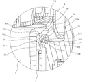
- FIG. 2 is an enlarged cross-sectional view of a portion A in FIG.
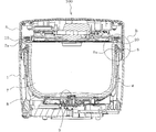
- FIG. 3 is a front sectional view showing the entire structure of the rice cooker according to the embodiment of the present invention.
- 4 is an enlarged cross-sectional view of a portion B in FIG.
- the rice cooker 100 according to the embodiment includes a main body 1 and a lid body 5 that is coupled to the main body 1 by a hinge 2 and is opened and closed by a latch 3 and a release button 4. Yes.
- the rice cooker 100 includes a resin inner case 6 having an opening 6a at the top and a coil base fixed to the bottom within the main body 1, and the inner case 6 includes an inner pot 7 Is housed freely.
- a heating coil 8 for electromagnetically heating the inner pot 7 is disposed on the outer periphery of the bottom of the coil base.
- a through hole is formed in the center of the bottom of the coil base, and a temperature sensor 9 for detecting the temperature of the inner hook 7 by contacting the lower surface of the inner hook 7 is installed in the through hole so as to be able to appear and retract.
- the heating coil 8 is supplied with high frequency power by a driving unit mounted on the power supply substrate 11 and electromagnetically heats the inner pot 7. That is, the drive unit converts the AC voltage from the commercial AC power source to DC once by a rectification unit (not shown), and then converts it to a high frequency by switching of the switching element, and supplies this high frequency current to the heating coil 8.
- the inner hook 7 has a flange 7 a formed at the upper end thereof, and this flange 7 a is placed and supported on the peripheral edge of the opening 6 a of the inner case 6 when stored in the inner case 6. Further, when the inner hook 7 is placed on the peripheral edge of the opening 6a of the inner case 6, a ring-shaped elastic member 20 made of silicon rubber having thermal insulation disposed on the peripheral edge of the opening 6a. Is in contact with the lower surface of the flange 7a, and the gap g between the inner peripheral surface of the inner case 6 and the outer peripheral surface of the inner hook 7 is closed. That is, the gap
- the elastic member 20 is arranged outside the inner peripheral wall 6b of the opening 6a of the inner case 6 as shown in FIGS.
- the elastic member 20 includes a ring-shaped base portion 20a that contacts the lower surface of the flange 7a of the inner hook 7, and an overhang portion 20b that projects outward from the ring-shaped base portion 20a over the entire circumference.
- a holding ring 21 that holds the elastic member 20 is disposed outside the elastic member 20.
- the elastic member 20 has an overhanging portion 20 b sandwiched between the holding ring 21 and the inner case 6 over the entire circumference. Fixed.
- annular protrusion 6c for positioning the elastic member is provided at a portion of the inner case 6 facing the protruding portion 20b of the elastic member 20.
- annular groove 20c into which the annular ridge 6c can be fitted is provided on the protruding portion 20b of the elastic member 20 facing the annular ridge 6c of the inner case 6. That is, the elastic member 20 is fixed by sandwiching the bottom of the annular groove 20c between the holding ring 21 and the annular protrusion 6c.
- the inner case 6 has an annular step 6d at a portion that is outside the elastic member 20 at the peripheral edge of the opening 6a.
- the holding ring 21 includes an inner ring portion 21a that holds the overhang portion 20b of the elastic member 20, and an outer ring portion that has a larger diameter than that of the inner ring portion 21a and a fitting portion 21d that can be press-fitted into the annular step portion 6d of the inner case 6 at the lower portion. 21b and connecting portions 21c and 21e that connect the inner ring portion 21a and the outer ring portion 21b.
- the retaining ring 21 has a thickness of the fitting portion 21d thinner than other portions of the retaining ring 21, and when viewed from the upper surface side of the inner case, the annular step portion 6d and the fitting portion 21d. A gap provided for easy assembly is covered with the holding ring 21 and is difficult to see.
- the holding ring 21 has a connecting portion 21 c (FIG. 4) other than the connecting portion 21 e (FIG. 2) located on the back side, formed on a slope inclined downward toward the outside. Since a space into which a finger can be inserted is formed below 7a, the inner hook 7 can be easily inserted and removed.
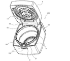
- FIG. 5 is a perspective view which shows the rice cooker which concerns on embodiment of this invention in the state which accommodated the inner pot and opened the cover body.
- FIG. 6 is a perspective view which shows the rice cooker which concerns on embodiment of this invention in the state which took out the inner pot and opened the cover body.
- a lid 5 that opens and closes the opening 6 a of the inner case 6 of the main body 1, and a latch 3 is provided on the main body 1 so as to be detachable from the lid 5.
- the holding ring 21 is fixed to the inner case 6 by screws 30 at two left and right positions on the front side and two right and left positions on the rear side.
- the color of the elastic member 20 made of silicon rubber and the color of the holding ring 21 made of resin are different from each other, thereby forgetting to attach the elastic member 20 during assembly. It is possible to prevent.
- the control unit starts controlling the drive unit.
- the drive unit converts the AC voltage from the commercial AC power source into DC once by the rectification unit, and then converts the AC voltage to high frequency by switching of the switching element, and this high frequency current is supplied to the heating coil 8.
- a high-frequency current flows through the heating coil 8
- an alternating magnetic field is generated from the heating coil 8 and a magnetic flux is applied to the inner pot 7.
- an eddy current is generated in the inner pot 7
- Joule heat is generated by the eddy current and the electric resistance of the inner pot 7, the inner pot 7 is heated, and rice cooking is performed.
- the gap g between the inner side of the inner hook 7 covered with the elastic member 20 and the outer side of the inner hook 7, that is, the inner peripheral surface of the inner case 6 and the outer peripheral surface of the inner hook 7 is also considerable. It becomes high temperature.
- the elastic member is divided and arranged at two right and left portions in the peripheral edge portion of the opening 6a of the inner case 6, heat is released from the gap g through a portion where the elastic member is not installed. I could't stop. For this reason, the heat in the gap g cannot be effectively utilized and is dissipated to the outside, and the rice cooking efficiency and the subsequent heat retention performance are not so high.
- the rice cooker 100 which concerns on embodiment of this invention has provided the ring-shaped elastic member 20 contact
- the elastic member 20 includes a ring-shaped base portion 20a that contacts the lower surface of the flange 7a of the inner hook 7, and an overhang portion 20b that projects outward from the ring-shaped base portion 20a over the entire circumference. Since the protruding portion 20b is sandwiched and fixed between the holding ring 21 and the inner case 6, the elastic member 20 can be prevented from being lifted.
- annular ridge 6c for positioning the elastic member is provided at a portion of the inner case 6 facing the protruding portion 20b of the elastic member 20, and the annular protrusion 6c of the inner case 6 in the elastic member 20 is opposed to the annular ridge 6c. Since the annular groove 20c into which the annular protrusion 6c can be fitted is provided in the projecting portion 20b, assembly work at the time of manufacture is facilitated.
- the elastic member 20 is fixed with the bottom of the annular groove 20c sandwiched between the retaining ring 21 and the annular protrusion 6c, the retaining ring 21 is elastic with a small pressing force (holding force). 20 can be held.
- an elastic member 20 made of silicon rubber having a higher frictional force than the inner peripheral wall 6b of the opening 6a of the resin inner case 6 is disposed on the outer side, and the inner hook peripheral surface is in contact with the inner hook 7 when the inner hook 7 is put in and out. Since the resin inner peripheral wall 6b is disposed, the inner hook 7 can be easily taken in and out.
- silicon rubber as the elastic member 20, it is easy to ensure durability and heat resistance, and the life can be extended.
Landscapes
- Engineering & Computer Science (AREA)
- Food Science & Technology (AREA)
- Manufacturing & Machinery (AREA)
- Cookers (AREA)
Abstract
Description
このようなものにおいて、弾性部材の固定は、この弾性部材の複数個所に設けたアンカー部を、溝の底部の複数個所に形成した取り付け孔に差し込むことで行っていた(例えば、特許文献1参照)。
また、弾性部材は、内釜のフランジの下面に当接するリング状の基部と、このリング状の基部から全周に亘って外向きに張り出す張出部とを備え、張出部が保持リングと内ケースとの間に全周に亘って挟まれて固定されるので、弾性部材の浮き上がりを防止できる。
なお、以下の説明において、理解を容易にするために位置を表す用語(例えば「上」、「下」、「前」、「後」など)を適宜用いるが、これは説明のためのものであって、これらの用語は本願発明を限定するものではない。
図1は本発明の実施形態に係る炊飯器の全体構成を示す側面視の断面図である。図2は図1のA部の拡大断面図である。図3は本発明の実施形態に係る炊飯器の全体構成を示す正面視の断面図である。図4は図3のB部の拡大断面図である。
実施形態に係る炊飯器100は、図1及び図3に示すように、本体1と、本体1にヒンジ2で結合されてラッチ3と解除ボタン4とによって開閉される蓋体5とを備えている。また、炊飯器100は、本体1内に、上部に開口部6aを有し、底部にコイル台が固定されている樹脂製の内ケース6を備えており、内ケース6には、内釜7が出し入れ自在に収容される。コイル台の底部外周には、内釜7を電磁誘導加熱する加熱コイル8が配置されている。また、コイル台には、その底部中央に、貫通穴が形成され、この貫通穴に、内釜7の下面に接触して内釜7の温度を検出する温度センサー9が出没自在に設置されている。加熱コイル8は、電源基板11に実装された駆動部によって高周波電力が供給され内釜7を電磁誘導加熱する。すなわち、駆動部は、商用交流電源からの交流電圧を、図示しない整流部で一旦直流に変換し、その後、スイッチング素子のスイッチングによって高周波に変換し、この高周波電流を加熱コイル8に供給する。
図5及び図6に示すように、本体1の内ケース6の開口部6aを開閉する蓋体5と、蓋体5と係脱自在に本体1にラッチ3が設けられており、保持リング21には、ラッチ3の係合部を覆うラッチカバー21fが一体に設けられている。ラッチカバー21fは、これまでは内ケース6側に設けられ、又は別体で構成されていた。そのため、金型構造が複雑となったり、部品点数が増える要因となっていた。ラッチカバー21fを保持リング21に一体に設けることで、部品点数を増やさず、かつ金型構造の簡素化を図ることができる。なお、保持リング21は、図5及び図6のように手前側の左右2個所と奥側の左右2個所で、それぞれねじ30によって内ケース6に固定されるようになっている。
Claims (7)
- 上部に開口部を有する内ケースを備えた本体と、
前記内ケースの前記開口部の周縁部に載置されるフランジを有し該内ケースに出し入れ自在に収納される内釜と、
前記内釜の前記フランジの下面に当接するように前記内ケースの前記開口部の前記周縁部に配置された熱絶縁性を有するリング状の弾性部材と、
前記弾性部材を保持する保持リングとを備え、
前記弾性部材は、前記内釜の前記フランジの下面に当接するリング状の基部と、該リング状の基部から全周に亘って外向きに張り出す張出部とを備え、該張出部が前記保持リングと前記内ケースとの間に全周に亘って挟まれて固定されている炊飯器。 - 前記内ケースにおける前記弾性部材の前記張出部と対向する部位に、弾性部材位置決め用の環状の突条が設けられているとともに、
前記弾性部材の前記張出部における前記内ケースの前記環状の突条と対向する部位に、該突条が嵌入できる環状の溝が設けられており、
前記弾性部材は、前記環状の溝の底部が前記保持リングと前記環状の突条との間に挟まれて固定されている請求項1記載の炊飯器。 - 前記内ケースの前記開口部の内周壁よりも前記弾性部材が外側に配置されている請求項1又は2記載の炊飯器。
- 前記内ケースは、前記開口部の前記周縁部における前記弾性部材よりも外側となる部位に環状の段部を有し、
前記保持リングは、前記弾性部材の前記張出部を押さえる内リング部と、それよりも大径で下部に前記内ケースの前記環状の段部内に嵌入できる嵌入部を有する外リング部と、これら内リング部と外リング部とを結ぶ連結部とを有し、前記嵌入部の肉厚が当該保持リングの他の部分よりも薄くなっている請求項1~3のいずれか一項に記載の炊飯器。 - 前記本体の前記内ケースの前記開口部を開閉する蓋体と、前記蓋体と係脱自在に前記本体に設けられたラッチと、前記ラッチを覆うラッチカバーとを更に備え、前記ラッチカバーと前記保持リングとが一体に構成されている請求項1~4のいずれか一項に記載の炊飯器。
- 前記弾性部材の色と前記保持リングの色とを異ならせた請求項1~5のいずれか一項に記載の炊飯器。
- 前記保持リングの連結部が外側に向かって下方に傾斜する斜面で形成されている請求項4~6のいずれか一項に記載の炊飯器。
Priority Applications (3)
| Application Number | Priority Date | Filing Date | Title |
|---|---|---|---|
| CN201480033347.4A CN105283101B (zh) | 2013-06-12 | 2014-06-02 | 电饭煲 |
| JP2015522717A JP5955462B2 (ja) | 2013-06-12 | 2014-06-02 | 炊飯器 |
| TW103119670A TWI519267B (zh) | 2013-06-12 | 2014-06-06 | Electric pot |
Applications Claiming Priority (2)
| Application Number | Priority Date | Filing Date | Title |
|---|---|---|---|
| JP2013123592 | 2013-06-12 | ||
| JP2013-123592 | 2013-06-12 |
Publications (1)
| Publication Number | Publication Date |
|---|---|
| WO2014199858A1 true WO2014199858A1 (ja) | 2014-12-18 |
Family
ID=52022156
Family Applications (1)
| Application Number | Title | Priority Date | Filing Date |
|---|---|---|---|
| PCT/JP2014/064649 Ceased WO2014199858A1 (ja) | 2013-06-12 | 2014-06-02 | 炊飯器 |
Country Status (4)
| Country | Link |
|---|---|
| JP (1) | JP5955462B2 (ja) |
| CN (1) | CN105283101B (ja) |
| TW (1) | TWI519267B (ja) |
| WO (1) | WO2014199858A1 (ja) |
Cited By (1)
| Publication number | Priority date | Publication date | Assignee | Title |
|---|---|---|---|---|
| JP2015002928A (ja) * | 2013-06-21 | 2015-01-08 | 三菱電機株式会社 | 炊飯器 |
Families Citing this family (4)
| Publication number | Priority date | Publication date | Assignee | Title |
|---|---|---|---|---|
| JP6141119B2 (ja) * | 2013-06-27 | 2017-06-07 | 三菱電機株式会社 | 炊飯器 |
| JP6057846B2 (ja) * | 2013-06-28 | 2017-01-11 | 三菱電機株式会社 | 炊飯器 |
| CN108697258B (zh) * | 2016-02-24 | 2020-07-28 | 三菱电机株式会社 | 电饭锅 |
| JP6678752B2 (ja) * | 2016-08-31 | 2020-04-08 | 三菱電機株式会社 | 炊飯器 |
Citations (8)
| Publication number | Priority date | Publication date | Assignee | Title |
|---|---|---|---|---|
| JPH021025U (ja) * | 1988-06-15 | 1990-01-08 | ||
| JPH10225375A (ja) * | 1997-02-13 | 1998-08-25 | Toshiba Home Technol Corp | 炊飯器 |
| JP2005090882A (ja) * | 2003-09-18 | 2005-04-07 | Mitsubishi Electric Corp | 加熱調理器 |
| JP2006334119A (ja) * | 2005-06-02 | 2006-12-14 | Toshiba Home Technology Corp | 炊飯器 |
| JP2007282977A (ja) * | 2006-04-19 | 2007-11-01 | Tiger Vacuum Bottle Co Ltd | 電気炊飯器 |
| JP2009172018A (ja) * | 2008-01-21 | 2009-08-06 | Nichiwa Denki Kk | 圧力調理器 |
| JP2010075521A (ja) * | 2008-09-26 | 2010-04-08 | Sanyo Electric Co Ltd | 電気炊飯器 |
| JP2010240328A (ja) * | 2009-04-10 | 2010-10-28 | Tiger Vacuum Bottle Co Ltd | 炊飯器 |
Family Cites Families (7)
| Publication number | Priority date | Publication date | Assignee | Title |
|---|---|---|---|---|
| JPH07298980A (ja) * | 1994-04-30 | 1995-11-14 | Mitsubishi Electric Corp | 炊飯器 |
| CN2774346Y (zh) * | 2005-02-25 | 2006-04-26 | 徐伟民 | 一种保鲜电饭煲 |
| JP4334510B2 (ja) * | 2005-08-01 | 2009-09-30 | 三菱電機株式会社 | 炊飯器 |
| JP4314222B2 (ja) * | 2005-08-10 | 2009-08-12 | 三菱電機株式会社 | 誘導加熱調理器 |
| JP5076369B2 (ja) * | 2006-06-08 | 2012-11-21 | タイガー魔法瓶株式会社 | 電気炊飯器 |
| WO2011161880A1 (ja) * | 2010-06-23 | 2011-12-29 | 三菱電機株式会社 | 炊飯器 |
| JP2012010925A (ja) * | 2010-06-30 | 2012-01-19 | Sanyo Electric Co Ltd | 炊飯器 |
-
2014
- 2014-06-02 JP JP2015522717A patent/JP5955462B2/ja active Active
- 2014-06-02 CN CN201480033347.4A patent/CN105283101B/zh not_active Expired - Fee Related
- 2014-06-02 WO PCT/JP2014/064649 patent/WO2014199858A1/ja not_active Ceased
- 2014-06-06 TW TW103119670A patent/TWI519267B/zh not_active IP Right Cessation
Patent Citations (8)
| Publication number | Priority date | Publication date | Assignee | Title |
|---|---|---|---|---|
| JPH021025U (ja) * | 1988-06-15 | 1990-01-08 | ||
| JPH10225375A (ja) * | 1997-02-13 | 1998-08-25 | Toshiba Home Technol Corp | 炊飯器 |
| JP2005090882A (ja) * | 2003-09-18 | 2005-04-07 | Mitsubishi Electric Corp | 加熱調理器 |
| JP2006334119A (ja) * | 2005-06-02 | 2006-12-14 | Toshiba Home Technology Corp | 炊飯器 |
| JP2007282977A (ja) * | 2006-04-19 | 2007-11-01 | Tiger Vacuum Bottle Co Ltd | 電気炊飯器 |
| JP2009172018A (ja) * | 2008-01-21 | 2009-08-06 | Nichiwa Denki Kk | 圧力調理器 |
| JP2010075521A (ja) * | 2008-09-26 | 2010-04-08 | Sanyo Electric Co Ltd | 電気炊飯器 |
| JP2010240328A (ja) * | 2009-04-10 | 2010-10-28 | Tiger Vacuum Bottle Co Ltd | 炊飯器 |
Cited By (1)
| Publication number | Priority date | Publication date | Assignee | Title |
|---|---|---|---|---|
| JP2015002928A (ja) * | 2013-06-21 | 2015-01-08 | 三菱電機株式会社 | 炊飯器 |
Also Published As
| Publication number | Publication date |
|---|---|
| CN105283101A (zh) | 2016-01-27 |
| JPWO2014199858A1 (ja) | 2017-02-23 |
| TW201519835A (zh) | 2015-06-01 |
| CN105283101B (zh) | 2017-03-08 |
| TWI519267B (zh) | 2016-02-01 |
| JP5955462B2 (ja) | 2016-07-20 |
Similar Documents
| Publication | Publication Date | Title |
|---|---|---|
| JP5955462B2 (ja) | 炊飯器 | |
| EP3297402B1 (en) | Induction cooking device | |
| JP5943775B2 (ja) | 電気炊飯器 | |
| JP6553151B2 (ja) | 電気炊飯器 | |
| JP4822915B2 (ja) | 炊飯器 | |
| KR102187884B1 (ko) | 워킹 코일 베이스 | |
| JP4799271B2 (ja) | 炊飯器 | |
| JP6057846B2 (ja) | 炊飯器 | |
| CN105286484A (zh) | 电饭煲 | |
| JP6141117B2 (ja) | 炊飯器 | |
| JP2014176406A (ja) | 炊飯器 | |
| JP6141119B2 (ja) | 炊飯器 | |
| JP5076369B2 (ja) | 電気炊飯器 | |
| CA3229506A1 (en) | Hookah device and improved consumable pod | |
| JP6045402B2 (ja) | 炊飯器 | |
| JP6856584B2 (ja) | 炊飯器 | |
| JP5943765B2 (ja) | 調理容器およびこれを用いた炊飯器 | |
| JP6273993B2 (ja) | 電気炊飯器 | |
| JP2011218070A (ja) | 炊飯器 | |
| JPH08190983A (ja) | 電磁誘導加熱調理器 | |
| JP2005174705A (ja) | 加熱調理器 | |
| CN219877977U (zh) | 煲体和烹饪器具 | |
| JP4591231B2 (ja) | 炊飯器 | |
| JP4992307B2 (ja) | 電気炊飯器 | |
| OA21567A (en) | Hookah device and improved consumable pod. |
Legal Events
| Date | Code | Title | Description |
|---|---|---|---|
| WWE | Wipo information: entry into national phase |
Ref document number: 201480033347.4 Country of ref document: CN |
|
| 121 | Ep: the epo has been informed by wipo that ep was designated in this application |
Ref document number: 14810862 Country of ref document: EP Kind code of ref document: A1 |
|
| ENP | Entry into the national phase |
Ref document number: 2015522717 Country of ref document: JP Kind code of ref document: A |
|
| NENP | Non-entry into the national phase |
Ref country code: DE |
|
| 122 | Ep: pct application non-entry in european phase |
Ref document number: 14810862 Country of ref document: EP Kind code of ref document: A1 |