WO2014199747A1 - 液体吐出装置、保湿キャップ及び保湿キャップ内の洗浄方法 - Google Patents
液体吐出装置、保湿キャップ及び保湿キャップ内の洗浄方法 Download PDFInfo
- Publication number
- WO2014199747A1 WO2014199747A1 PCT/JP2014/062293 JP2014062293W WO2014199747A1 WO 2014199747 A1 WO2014199747 A1 WO 2014199747A1 JP 2014062293 W JP2014062293 W JP 2014062293W WO 2014199747 A1 WO2014199747 A1 WO 2014199747A1
- Authority
- WO
- WIPO (PCT)
- Prior art keywords
- liquid
- moisturizing
- discharge
- moisturizer
- level
- Prior art date
- Legal status (The legal status is an assumption and is not a legal conclusion. Google has not performed a legal analysis and makes no representation as to the accuracy of the status listed.)
- Ceased
Links
Images




Classifications
-
- B—PERFORMING OPERATIONS; TRANSPORTING
- B41—PRINTING; LINING MACHINES; TYPEWRITERS; STAMPS
- B41J—TYPEWRITERS; SELECTIVE PRINTING MECHANISMS, i.e. MECHANISMS PRINTING OTHERWISE THAN FROM A FORME; CORRECTION OF TYPOGRAPHICAL ERRORS
- B41J2/00—Typewriters or selective printing mechanisms characterised by the printing or marking process for which they are designed
- B41J2/005—Typewriters or selective printing mechanisms characterised by the printing or marking process for which they are designed characterised by bringing liquid or particles selectively into contact with a printing material
- B41J2/01—Ink jet
- B41J2/135—Nozzles
- B41J2/165—Prevention or detection of nozzle clogging, e.g. cleaning, capping or moistening for nozzles
-
- B—PERFORMING OPERATIONS; TRANSPORTING
- B41—PRINTING; LINING MACHINES; TYPEWRITERS; STAMPS
- B41J—TYPEWRITERS; SELECTIVE PRINTING MECHANISMS, i.e. MECHANISMS PRINTING OTHERWISE THAN FROM A FORME; CORRECTION OF TYPOGRAPHICAL ERRORS
- B41J2/00—Typewriters or selective printing mechanisms characterised by the printing or marking process for which they are designed
- B41J2/005—Typewriters or selective printing mechanisms characterised by the printing or marking process for which they are designed characterised by bringing liquid or particles selectively into contact with a printing material
- B41J2/01—Ink jet
- B41J2/135—Nozzles
- B41J2/165—Prevention or detection of nozzle clogging, e.g. cleaning, capping or moistening for nozzles
- B41J2/16505—Caps, spittoons or covers for cleaning or preventing drying out
- B41J2/16508—Caps, spittoons or covers for cleaning or preventing drying out connected with the printer frame
-
- B—PERFORMING OPERATIONS; TRANSPORTING
- B41—PRINTING; LINING MACHINES; TYPEWRITERS; STAMPS
- B41J—TYPEWRITERS; SELECTIVE PRINTING MECHANISMS, i.e. MECHANISMS PRINTING OTHERWISE THAN FROM A FORME; CORRECTION OF TYPOGRAPHICAL ERRORS
- B41J2/00—Typewriters or selective printing mechanisms characterised by the printing or marking process for which they are designed
- B41J2/005—Typewriters or selective printing mechanisms characterised by the printing or marking process for which they are designed characterised by bringing liquid or particles selectively into contact with a printing material
- B41J2/01—Ink jet
- B41J2/135—Nozzles
- B41J2/165—Prevention or detection of nozzle clogging, e.g. cleaning, capping or moistening for nozzles
- B41J2/16517—Cleaning of print head nozzles
- B41J2/1652—Cleaning of print head nozzles by driving a fluid through the nozzles to the outside thereof, e.g. by applying pressure to the inside or vacuum at the outside of the print head
- B41J2/16523—Waste ink transport from caps or spittoons, e.g. by suction
-
- B—PERFORMING OPERATIONS; TRANSPORTING
- B41—PRINTING; LINING MACHINES; TYPEWRITERS; STAMPS
- B41J—TYPEWRITERS; SELECTIVE PRINTING MECHANISMS, i.e. MECHANISMS PRINTING OTHERWISE THAN FROM A FORME; CORRECTION OF TYPOGRAPHICAL ERRORS
- B41J2/00—Typewriters or selective printing mechanisms characterised by the printing or marking process for which they are designed
- B41J2/005—Typewriters or selective printing mechanisms characterised by the printing or marking process for which they are designed characterised by bringing liquid or particles selectively into contact with a printing material
- B41J2/01—Ink jet
- B41J2/135—Nozzles
- B41J2/165—Prevention or detection of nozzle clogging, e.g. cleaning, capping or moistening for nozzles
- B41J2/16585—Prevention or detection of nozzle clogging, e.g. cleaning, capping or moistening for nozzles for paper-width or non-reciprocating print heads
Definitions
- the present invention relates to a liquid discharge device, a moisturizing cap, and a cleaning method in a moisturizing cap, and more particularly to a maintenance technique of a moisturizing cap provided at a standby position of a liquid discharge head.
- the ink jet recording apparatus it is necessary to prevent the ink in the nozzles from being dried. For this reason, at the time of standby, the nozzle face of the discharge head is covered with a moisturizing cap in which the moisturizing liquid is stored inside, and the transpiration action of the moisturizing liquid is performed to maintain the humidity in the vicinity of the nozzle within a desired range.
- the inside of the moisturizing cap is periodically washed and cleaned regularly.
- Patent Document 1 describes that the discharge port is provided at a position lower than the position at which the solvent supply port is provided in order to suppress the solid component from remaining in the inside of the capping unit in contact with the discharge head. There is.
- Patent Document 2 describes a moisturizing cap having a bottom surface of the cap inclined and having a wipe blade for wiping the thickened ink remaining on the surface.
- the ink jet printer provided with the moisture retention cap described in Patent Document 1 has a problem that the cleaning time is long and the amount of the solvent used for the cleaning is also large.
- the present invention has been made in view of such circumstances, and the frequency of periodic cleaning can be reduced or unnecessary, and a liquid discharge device capable of cleaning in a short time, a moisturizing cap, and cleaning in the moisturizing cap Intended to provide a method.
- the present invention provides a liquid discharge head having a nozzle surface on which a plurality of nozzles for discharging a liquid are disposed, a liquid reservoir having a bottom inclined with respect to a horizontal surface, and holding a moisturizer.
- a moisturizing cap having a supply port for supplying a moisturizing liquid to the liquid reservoir and a discharge port provided on the bottom so as to be disposed lower than the supply port and discharging the moisturizing liquid and moisturizing the nozzle surface;
- a moving means for moving the liquid discharge head to an image forming position where the liquid discharge head discharges the liquid to form an image on the medium, and a standby position to moisturize the nozzle surface, and a moisturizer stored in the liquid reservoir.
- a moisturizing liquid control means for controlling the liquid level height, wherein the moisturizing liquid control means discharges from the discharge port the moisturizing liquid accumulated to the first liquid level in the liquid reservoir, and the moisturizing liquid When the liquid level is at the second level, drain the moisturizer from the outlet.
- a liquid discharge device for supplying a moisturizing liquid from the supply port and stopping the discharge of the moisturizing liquid from the discharge port while supplying the moisturizing liquid from the supply port when the moisturizer reaches a third liquid level provide.
- the present invention has a liquid reservoir portion having a bottom inclined with respect to a horizontal surface, which holds the moisturizing liquid, a supply port for supplying the moisturizing liquid to the liquid reservoir portion, and a lower position than the supply port. And a plurality of nozzles for discharging liquid, each having a discharge port for the moisturizing liquid and a moisturizing liquid control means for controlling the level of the moisturizing liquid accumulated in the liquid reservoir.
- a moisturizing cap for moisturizing the nozzle surface of the disposed liquid discharge head wherein the moisturizing liquid control means discharges from the discharge port the moisturizing liquid accumulated to the first liquid level in the liquid reservoir, and the moisturizing liquid When the second liquid level is reached, the moisturizing liquid is supplied from the supply port while discharging the moisturizing liquid from the discharge port, and when the moisturizing liquid reaches the third liquid level, the supply port.
- the moisturizing cap that stops the discharge of the moisturizing solution from the discharge port while supplying the moisturizing solution.
- the present invention has a bottom portion which is inclined with respect to a horizontal surface, a liquid reservoir for holding the moisturizer, a supply port for supplying the moisturizer to the liquid reservoir and a supply port lower than the supply port.
- the first step of discharging the moisturizing liquid stored in the liquid reservoir to the first liquid level to the second liquid level from the discharge port, and the discharging of the moisturizing liquid after the first step In the second step of continuously supplying the moisturizing liquid from the supply port, and when the moisturizing liquid reaches the third level, the moisturizing liquid is continuously supplied to stop discharging the moisturizing liquid from the discharge port. And a third step of providing a cleaning method in the moisturizing cap.
- the liquid storage portion of the moisturizing cap for retaining the moisturizing liquid has a bottom inclined with respect to the horizontal plane, and the discharge port is provided at a position lower than the supply port of the moisturizing liquid. Moistened fluid flows along the bottom to the outlet.
- the moisturizing liquid accumulated to the first liquid level in the liquid reservoir is discharged from the discharge port, and when the moisturizing liquid is discharged to the second liquid level, until the third liquid level is reached,
- the moisturizer is supplied from the supply port while discharging the moisturizer.
- the moisturizing liquid is supplied from the supply port while discharging the moisturizing liquid to the third liquid level, so the moisturizing liquid in the liquid reservoir portion is disturbed. A flow occurs, and the moisturizer in the reservoir is agitated and discharged from the outlet.
- the liquid reservoir can be cleaned, and the moisturizer in the liquid reservoir can be made clean to some extent with little ink contamination.
- cleaning of a liquid storage part can be decreased.
- the frequency of regular cleaning can be reduced or unnecessary, and a liquid discharge device capable of cleaning in a short time, a moisturizing cap, and a cleaning method in the moisturizing cap can be provided.
- the third liquid level may be lower or higher than the second liquid level.
- the third liquid level and the second liquid level are different if the ability to discharge the moisturizing liquid and the ability to supply the moisturizing liquid are constant, respectively. Is preferred.
- the moisturizing liquid control means when the moisturizing liquid reaches a third level, supplies the moisturizing liquid from the supply port until the moisturizing liquid reaches the first height. preferable. Thereby, before and after washing
- the moisturizer control means preferably controls the liquid level of the moisturizer based on the time calculated from the ability to supply the moisturizer and the ability to discharge the moisturizer.
- the liquid storage unit further includes a level sensor provided in the liquid storage unit to detect the liquid level of the moisturizing liquid stored in the liquid storage unit, and the moisturizing liquid control unit performs moisturization based on the detection value of the level sensor. It is preferred to control the discharge and supply of the liquid.
- the liquid discharge head further includes a humidity sensor provided on the nozzle surface of the liquid discharge head to detect humidity, and the moisturizer control means determines the humidity value in advance when the liquid discharge head is in the standby position.
- the moisturizing liquid control means execute control of the liquid level of the moisturizing liquid every predetermined time calculated based on the evaporation time of the moisturizing liquid.
- the moisturizing liquid control means By performing discharge and supply of the moisturizing liquid by the moisturizing liquid control means at any of these timings, not only the moisturizing liquid with few ink stains but also the nozzle surface and the moisturizing liquid surface resulting from the evaporation of the moisturizing liquid Since it is possible to eliminate the reduction of the distance between the two, it is possible to preferably maintain the moisturizing effect.
- the moisturizing cap comprises a moisturizing fluid tank for retaining the moisturizing fluid, moisturizing fluid supply means for supplying the moisturizing fluid in the moisturizing fluid tank to the liquid reservoir, and recovering the moisturizing fluid discharged from the liquid reservoir. And a moisturizing liquid recovery tank. Thereby, the inside of the moisturizing cap can be cleaned.
- a filter for removing the contamination of the moisturizing fluid in the moisturizing fluid recovery tank and a moisturizing fluid circulation means for supplying the moisturizing fluid that has passed through the filter to the moisturizing fluid tank may be further provided.
- the moisturizer can be effectively used without wasting it.
- a liquid discharge device a moisturizing cap, and a cleaning method in the moisturizing cap, which can reduce or eliminate the frequency of periodic cleaning, and can be cleaned in a short time.
- FIGS. 3A to 3C are plan perspective views showing an example of the structure of the ink jet head.
- Sectional view showing a three-dimensional configuration of the ink chamber unit Flow path diagram showing the flow path structure inside the head module
- Block diagram showing system configuration of inkjet recording apparatus Front view showing the inkjet head and the moisturizing cap Front view showing the composition of the moisturizing cap
- Flow chart showing cleaning operation of moisturizing cap
- Side view showing the configuration of the main part of the inkjet recording apparatus
- Top view showing the configuration of the main part of the inkjet recording apparatus
- Perspective view showing a moisturizing cap (moisturizing unit)
- Sectional view showing a moisturizing unit and an inkjet head
- FIG. 1 is a side view showing the ink jet recording apparatus according to the present embodiment.
- the inkjet recording apparatus 100 includes an inkjet head 120 (a liquid ejection head) on a recording surface of a sheet 1 (an example of a medium (recording medium)) conveyed in the horizontal direction (Y direction) by a conveyance unit 110 (an example of a moving unit).
- a conveyance unit 110 an example of a moving unit.
- Example is a printer that ejects ink from the nozzle surface 122 to form an image.
- FIG. 2 is a plan view of the inkjet recording apparatus 100.
- the inkjet recording apparatus 100 includes a moisture retention cap 140 in a direction (X direction) orthogonal to the conveyance direction (Y direction) of the sheet 1 by the conveyance unit 110.
- the inkjet head 120 is held by the head holder 130, and is configured to be movable in the X direction by a head moving mechanism (not shown).
- a head moving mechanism not shown.
- the inkjet head 120 is moved from the position where an image can be formed on the sheet 1 (image forming position) to the position on the moisturizing cap 140 side (moisturizing position).
- the nozzle face 122 is covered with the moisturizing cap 140. This prevents non-ejection due to drying.
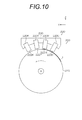
- FIG. 3 is a view showing a structural example of the ink jet head 120.
- FIG. 3 (a) is a plan perspective view seen from the nozzle surface 122 side
- FIG. 3 (b) is an enlarged view of a part thereof
- FIG. 3 (c) is configured from the head module 120a.
- FIG. 6 is a plan perspective view of the entire inkjet head 120.
- 4 is a cross-sectional view showing a three-dimensional configuration of the ink chamber unit (a cross-sectional view taken along the line IV-IV in FIGS. 3A and 3B), and
- FIG. 5 shows the inside of the head module 120a.
- It is a flow-path block diagram (the plane perspective view seen from the A direction in FIG. 4) which shows a flow-path structure.
- the nozzle surface 122 (an example of a liquid discharge surface) of the inkjet head 120 is formed to be flat. Further, on the nozzle surface 122, a plurality of nozzles 51 which are ejection holes of ink droplets are arranged. In order to densify the dot pitch formed on the paper 1, it is necessary to densify the nozzle pitch.
- the ink jet head 120 according to the present embodiment has a plurality of ink chamber units 53 including pressure chambers 52 and the like corresponding to the respective nozzles 51 arranged in a fixed array pattern. It has a (two-dimensionally) arranged structure. Thereby, the densification of the substantial nozzle spacing (projected nozzle pitch) projected to be aligned along the head longitudinal direction (Y direction) is achieved.
- a long ink jet head 120 having a nozzle row having a length corresponding to the entire width of the recording medium is obtained. It may be configured. Although not shown, short head modules may be arranged in a line to form a long ink jet head.
- the embodiment in which one or more nozzle rows are formed over a length corresponding to the entire width of the recording medium in a direction substantially orthogonal to the paper conveyance direction is not limited to this embodiment.
- the pressure chambers 52 provided corresponding to the nozzles 51 have a substantially square planar shape, and the nozzles 51 and the ink inlet 54 are provided at diagonally opposite corners.
- Each pressure chamber 52 is in communication with an individual flow passage 59 (an example of a supply flow passage) via an ink inlet 54, and each individual flow passage 59 is in communication with a common flow passage 55.
- the nozzle flow passage 60 communicating with each pressure chamber 52 is in communication with the circulation common flow passage 64 via the individual circulation flow passage 62.
- the ink jet head 120 is provided with a supply port 66 (an example of a liquid supply port) and a discharge port 68 (an example of a liquid discharge port), the supply port 66 is in communication with the common flow channel 55, and the discharge port 68 is a circulation common. It is in communication with the flow path 64.
- the supply port 66 and the discharge port 68 of the inkjet head 120 are the common flow channel 55, the individual flow channel 59, the ink inlet 54, the pressure chamber 52, the nozzle flow channel 60, the individual circulation flow channel 62, and the circulation common flow channel. It is configured to be in communication via an ink flow path (internal flow path) including the F.64.
- the individual circulation channel 62 be connected in the vicinity of the nozzle 51 of the nozzle channel 60. According to such a configuration, since the ink circulates in the vicinity of the nozzle 51, thickening of the ink inside the nozzle 51 is prevented, and stable discharge becomes possible.
- a piezoelectric element 58 (an example of a pressure generating means) provided with an individual electrode 57 is joined to a diaphragm 56 which constitutes a top surface of the pressure chamber 52 and also serves as a common electrode.
- the piezoelectric element 58 is deformed and ink is ejected from the nozzle 51.
- new ink is supplied to the pressure chamber 52 from the common flow channel 55 through the individual flow channels 59 and the ink inlet 54.
- the piezoelectric element 58 is applied as a discharge force generation means of the ink discharged from the nozzle 51 provided in the ink jet head 120, but a heater is provided in the pressure chamber 52 and the pressure of film boiling due to heating of the heater is used. It is also possible to apply a thermal method in which ink is ejected.
- the ink chamber units 53 having such a structure are arranged in a row along the main scanning direction and a fixed array along the oblique column direction having a constant angle ⁇ not orthogonal to the main scanning direction.
- the high density nozzle head of this example is realized by arranging a large number of patterns in a lattice.
- the nozzle pitch Px projected to be aligned in the main scanning direction P ⁇ cos ⁇ Therefore, in the main scanning direction, it can be treated equivalently to one in which the nozzles 51 are linearly arranged at a constant pitch Px. With such a configuration, it is possible to realize a high-density nozzle configuration in which the number of nozzle rows projected so as to be aligned in the main scanning direction reaches 2400 nozzles per inch (2400 nozzles / inch).
- the nozzle arrangement structure is not limited to the illustrated example, and various nozzle arrangement structures such as an arrangement structure having one nozzle row in the sub-scanning direction can be applied.
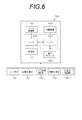
- FIG. 6 is a block diagram showing the system configuration of the inkjet recording apparatus 100.
- the inkjet recording apparatus 100 includes an ink circulation unit 150, a moving mechanism (moving unit) 160, a user interface 172, and a recording control unit 174, in addition to the above-described transport unit 110, inkjet head 120, and moisturizing cap 140.
- the ink circulation unit 150 (an example of a circulation unit) includes a pipe, a valve, an ink tank, a pump, and the like (not shown), and is connected to the inkjet head 120 via the valve.
- the ink circulation unit 150 supplies the ink from the supply port 66 of the inkjet head 120. Further, the ink not ejected from the nozzles is collected from the discharge port 68, and the ink is circulated between the inkjet head 120 and the ink tank.
- the ink circulation unit 150 circulates the ink so that the back pressure of the nozzle 51 (the internal pressure of the inkjet head 120) becomes a negative pressure.
- the negative pressure refers to a pressure smaller than the atmospheric pressure.
- the moving mechanism 160 moves the ink jet head 120 to an image forming position or a moisturizing position. Further, as described later, the moving mechanism 160 is configured to be able to change the distance between the ink jet head 120 and the moisturizing cap 140.
- the user interface 172 is a power switch for turning on / off / off the power of the ink jet printing apparatus 100, an input unit (not shown) for the user to operate the ink jet printing apparatus 100, a warning display, etc. And an output unit (not shown).
- a recording control unit 174 controls conveyance of the sheet 1 by the conveyance unit 110, discharge of ink by the inkjet head 120, and the like, and an image is printed on the recording surface of the sheet 1 based on input image data.
- the ink circulation control unit 176 controls the ink circulation unit 150 to control the presence or absence of ink circulation to the inkjet head 120 and the amount of circulation ink.
- the movement control unit 178 controls the movement mechanism 160 to control the position of the inkjet head 120.
- the moisturizing liquid control unit 180 controls the height of the liquid level of the moisturizing liquid 146 accumulated in the liquid reservoir 142 described later. Specifically, the supply or discharge of the moisturizing liquid 146 into the moisturizing cap 140 is controlled.
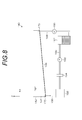
- FIG. 7 is a view schematically showing the moisture retention cap 140 and the inkjet head 120 moved to the moisture retention position (standby position).
- a liquid reservoir 142 is provided inside the moisture retention cap 140.
- a moisturizing liquid 146 for moisturizing the nozzle surface 122 of the ink jet head 120 is accumulated in the liquid reservoir 142.
- the moisturizing liquid 146 is a liquid containing the same solvent as the solvent of the ink ejected from the nozzle 51 of the ink jet head 120, and is, for example, a liquid whose main component is water.
- the bottom surface 144 of the liquid reservoir 142 is inclined with respect to the horizontal plane and the longitudinal direction of the inkjet head 120 (the X direction in the drawing).
- the liquid reservoir 142 is provided with a supply port 173 for supplying the moisturizing liquid 146 into the liquid reservoir 142 and a discharge port 175 for discharging the moisturizing liquid 146 in the liquid reservoir 142.
- the discharge port 175 is at a lower position (lower position with respect to the vertical direction) than the supply port 173, and is provided on the bottom surface 144.
- the position of the supply port 173 is preferably as far as possible from the discharge port 175.
- FIG. 8 is a front view showing an example of the configuration of the moisture retention cap 140. As shown in FIG.
- a moisturizer tank 182 As shown in the figure, it comprises a moisturizer tank 182, a moisturizer supply passage 184, a moisturizer discharge passage 186, a waste liquid tank 188, a moisturizer circulation passage 190, a filter 194, pumps 192 and 196, and the like.
- a member for receiving the moisturizing fluid overflowed, a discharge path for collecting the moisturizing fluid received by this member, and the like are provided outside the liquid reservoir 142.
- a moisturizer is stored in the moisturizer tank 182.
- This moisturizer may be a washing solution, and may contain a preservative to prevent the generation of mold.
- the moisturizer tank 182 supplies the moisturizer with a constant flow rate to the liquid reservoir 142 by the pump 196 through the moisturizer supply path 184.
- the moisturizing liquid accumulated in the liquid reservoir 142 flows by the pump 192 and is stored in the waste liquid tank 188 via the moisturizing liquid discharge path 186. As a result, the moisturizing liquid in the liquid reservoir 142 is discharged at a constant flow rate.
- the moisturizer stored in the waste liquid tank 188 is introduced by the pump 192 into the moisturizer tank 182 via the moisturizer circulation path 190.
- the moisturizer circulation path 190 is provided with a filter 194 for removing foreign substances and dirt of the moisturizer stored in the waste liquid tank 188.
- the liquid reservoir 142 of the moisture retention cap 140 can be filled with the moisture retention liquid. Therefore, the nozzle surface 122 of the inkjet head 120 can be moisturized for a long time. Also, there is no need to waste moisturizer.
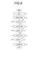
- Step S1 Perform initialization.
- the inkjet head 120 is moved to the moisturizing position (standby position) where the moisturizing cap 140 is located.
- Step S2 The liquid reservoir 142 is full (in this embodiment, the liquid level when the moisturizing liquid 146 is full is filled with h1 (first liquid level)).
- the moisturizer 146 starts to be discharged from the discharge port 175.
- the first liquid level height h1 is not limited to the height of the liquid level when the moisturizing liquid 146 is full in the liquid reservoir 142, and can be set as appropriate.
- Step S3 By discharging the moisturizing liquid 146, it is determined whether the liquid level of the moisturizing liquid 146 in the liquid reservoir 142 has become h2 (second liquid level height). That is, it is determined whether the moisturizing liquid 146 has been discharged until the liquid level becomes h2.
- the liquid level height h2 (second liquid level height) is lower than the liquid level height h1 (first liquid level height).
- Step S4 When the liquid level of the moisturizing liquid 146 in the liquid reservoir 142 becomes h2 (second liquid level), the supply of the moisturizing liquid 146 into the liquid reservoir 142 from the supply port 173 is started. At this time, discharge of the moisturizing liquid 146 is continued.
- Step S5 It is determined whether the liquid level of the moisturizing liquid 146 in the liquid reservoir 142 has become h3 (third liquid level) by the discharge and supply of the moisturizing liquid 146.
- Step S6 When the liquid level of the moisturizing liquid 146 in the liquid reservoir 142 becomes h3 (third liquid level), the discharge of the moisturizing liquid 146 from the discharge port 175 is stopped. At this time, the supply of the moisturizing liquid 146 is continued.
- Step S7 It is determined whether or not the liquid level of the moisturizing liquid 146 in the liquid reservoir 142 has become h1 (the first liquid level) by the supply of the moisturizing liquid 146.
- Step S8 When the liquid level of the moisturizing liquid 146 in the liquid reservoir 142 becomes h1 (first liquid level), the supply of the moisturizing liquid 146 from the supply port 173 is stopped.
- the liquid reservoir portion 142 of the moisturizing cap 140 for retaining the moisturizing liquid 146 has a bottom surface 144 which is inclined with respect to the horizontal plane and the longitudinal direction of the liquid discharge head 120. Since the discharge port 175 is provided at the position of the bottom surface 144 lower than 173, the moistened liquid 146 contaminated with the ink flows to the discharge port 175.
- the moisturizing liquid 146 stored in the liquid reservoir 142 to the first liquid level h1 is discharged from the discharge port 175 (first step) and the moisturizing liquid 146 is discharged to the second liquid level h2
- the moisturizing liquid 146 is supplied from the supply port 173 while continuing the discharge of the moisturizing liquid 146 until the third liquid level h3 is reached (second step).
- turbulent flow occurs in the moisturizing liquid 146 of the liquid reservoir 142, and the moisturizing liquid 146 of the liquid reservoir 142 is agitated and discharged from the discharge port 175.
- the liquid reservoir 142 is cleaned, and the moisturizing liquid in the liquid reservoir 142 can be made into a moist cleanser 146 with a certain degree of ink contamination.
- the washing time can be shortened and the amount of the moisturizing liquid 146 used for washing the liquid reservoir 142 can be reduced.
- the frequency of regular cleaning in the moisture retention cap 140 by a person can be reduced or unnecessary, and washing in the moisture retention cap 140 can be performed in a short time.
- the third liquid level height h3 may be lower or higher than the second liquid level height h2.
- the third liquid level height h3 And the second liquid level height h2 are preferably different.
- the second liquid level height h2 and the third liquid level height h3 are preferably in the range of 20 to 80% of the first liquid level h1.
- the second liquid level height h2 can be 60% of the first liquid level height h1
- the third liquid level h3 can be 50% of the first liquid level h1.
- the preferable second liquid level height h2 and third liquid level height h3 are the physical properties of the moisturizing liquid 146 used, the discharge capacity of the discharge port 175 of the liquid reservoir 142, the supply capacity of the supply port 173, It can be set appropriately according to the inclination angle of the bottom surface 144 or the like. Therefore, it is desirable to determine the preferable second liquid level height h2 and the third liquid level height h3 through preliminary experiments.
- the liquid level heights h1 to h3 of the moisturizing liquid 146 of the liquid reservoir 142 can be calculated based on the time calculated from the ability to supply the moisturizing liquid 146 and the ability to discharge the moisturizing liquid 146.
- a level sensor (not shown) for detecting the liquid level of the moisturizing liquid 146 is provided in the liquid reservoir 142, and the liquid level of the moisturizing liquid 146 is controlled based on the detection value of this level sensor. May be
- a humidity sensor is provided on the nozzle surface 122 of the liquid ejection head 120, and the humidity value is predetermined when the liquid ejection head is in the standby position. It is preferable to execute the discharge and supply of the moisturizing fluid 146 by the moisturizing fluid control means 180 when it is detected lower than the value. Alternatively, discharging and supplying of the moisturizing liquid 146 by the moisturizing liquid control unit 180 may be performed at predetermined time intervals calculated based on the evaporation time of the moisturizing liquid 146 (the liquid level of the moisturizing liquid 146 may be adjusted). preferable.
- the moisturizing liquid control means 180 By discharging and supplying the moisturizing liquid 146 by the moisturizing liquid control means 180 at any of these timings, not only the moisturizing liquid with few ink stains but also the nozzle surface 122 resulting from the evaporation of the moisturizing liquid 146 Eliminate the decrease in the distance between the moisturizing liquid surface, and detect the humidity decrease due to the film such as latex contained in the ink to execute the discharge and supply of the moisturizing liquid 146 (the liquid surface of the moisturizing liquid 146 Since the height can be adjusted, the moisturizing effect can be suitably maintained.
- FIG. 10 is a side view showing the configuration of the main part of the ink jet recording apparatus according to the present embodiment
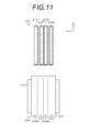
- FIG. 11 is a top view.
- the ink jet recording apparatus 200 is a single pass type line printer.
- the inkjet recording apparatus 200 mainly transports the sheet 1 serving as a recording medium, and the cyan (C), magenta (M), yellow (Y), and black (A) toward the sheet 1 conveyed by the conveyance drum 210.
- a head unit 220 that ejects each color ink droplet of K) and a moisturizing unit 240 that moisturizes each inkjet head mounted on the head unit 220 are configured.
- the conveyance drum 210 is driven to rotate by a motor (not shown).
- Grippers (not shown) are provided on the outer peripheral surface of the transport drum 210, and the sheet 1 is transported while its leading edge is gripped by the grippers.
- a large number of suction holes (not shown) are formed on the outer peripheral surface of the transport drum 210, and air is sucked from the suction holes toward the inside. The sheet 1 is conveyed while being held by suction in the suction holes.
- the head unit 220 includes inkjet heads 220C, 220M, 220Y, and 220K that respectively eject cyan, magenta, yellow, and black ink droplets, a head holding unit 230 to which the inkjet heads 220C, 220M, 220Y, and 220K are attached, and the head And a moving mechanism (not shown) for moving the holding unit 230.
- the inkjet heads 220C, 220M, 220Y, and 220K are line heads corresponding to the maximum sheet width (the width in the X direction) of the sheet 1 as an image formation target.
- Each of the ink jet heads 220C, 220M, 220Y and 220K is formed in a rectangular block shape, and nozzle surfaces 222C, 222M, 222Y and 222K are formed at the bottoms thereof. Further, the number of nozzles formed on the nozzle surfaces 222C, 222M, 222Y and 222K and the arrangement form thereof are not particularly limited.
- the inkjet heads 220C, 220M, 220Y, and 220K eject ink from the nozzles by a piezo method or a thermal method.
- the head holding portion 230 includes a head attachment portion (not shown) for attaching the ink jet heads 220C, 220M, 220Y and 220K.
- the inkjet heads 220C, 220M, 220Y, and 220K are detachably attached to the head attachment portion.
- the inkjet heads 220C, 220M, 220Y, and 220K attached to the head holding unit 230 are disposed orthogonal to the conveyance direction (Y direction) of the sheet 1. In addition, they are arranged at predetermined intervals in a predetermined order along the transport direction of the sheet 1. In the present embodiment, cyan, magenta, yellow and black are arranged in this order.
- the inkjet heads 220C, 220M, 220Y, and 220K are attached to the head holding portion 230 such that the nozzle surfaces 222C, 222M, 222Y, and 222K are parallel to the tangent of the circumferential surface of the conveying drum 210 facing each other. . That is, the nozzle faces 222C, 222M, 222Y and 222K are not parallel to the horizontal plane, but form an angle.
- the moving mechanism slides the head holder 230 horizontally in the X direction.
- the moving mechanism includes a ceiling frame horizontally installed across the transfer drum 210 and the moisture retention unit 240, a guide rail laid on the ceiling frame, a traveling body slidingly moving on the guide rail, and the traveling body And a drive means (e.g., a feed screw mechanism etc.) for moving along the guide rail.
- the head holder 230 is attached to the traveling body and slides horizontally.
- the head holding unit 230 is driven by the moving mechanism to move between the “image forming position” and the “humidifying position”.
- the head holder 230 When the head holder 230 is at the image forming position, the head holder 230 is disposed above the transport drum 210. As a result, it is possible to discharge an ink of each color and record an image on the recording surface of the sheet 1 conveyed by the conveyance drum 210.
- the head holding unit 230 when the head holding unit 230 is in the moisturizing position, the head holding unit 230 is disposed at the installation position of the moisturizing unit 240.
- FIG. 12 is a perspective view of the moisture retention unit 240
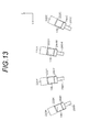
- FIG. 13 is a cross section perpendicular to the width direction (X direction), and shows the head unit 220 moved to the moisture retention position viewed from the near side ( ⁇ X direction). It is the schematic which showed the moisture retention unit 240 typically.
- the moisturizing unit 240 includes moisturizing caps 240C, 240M, 240Y and 240K for moisturizing the nozzle surfaces 222C, 222M, 222Y and 222K of the respective inkjet heads 220C, 220M, 220Y and 220K.
- a moisturizing liquid 146 for moisturizing the nozzle surfaces 222C, 222M, 222Y and 222K of the inkjet heads 220C, 220M, 220Y and 220K is filled in the inside (liquid reservoir) of the moisturizing caps 240C, 240M, 240Y and 240K. There is.
- the bottoms 244C, 244M, 244Y, and 244K of the liquid reservoirs are inclined with respect to the horizontal plane and the longitudinal direction of the inkjet head 120 (the X direction in the drawing).
- the moisturizing caps 240C, 240M, 240Y and 240K respectively supply moisturizing fluid 146 to the inside (liquid reservoir) of the moisturizing caps 240C, 240M, 240Y and 240K, and moisturizing caps 284C, 284M, 284Y and 284K
- moisturizing fluid discharge paths 286C, 286M, 286Y and 286K for draining the moisturizing fluid 146 in the interior (liquid reservoir) of 240C, 240M, 240Y and 240K.
- the discharge ports of the moisturizing fluid discharge channels 286C, 286M, 286Y, and 286K are located at a lower height (lower position with respect to the vertical direction) than the moisturizing fluid supply channels 284C, 284M, 284Y, and 284K. It is provided in 244C, 244M, 244Y, 244K.
- the moisturizing caps 240C, 240M, 240Y and 240K are configured such that the opening faces are in parallel with the nozzle faces 222C, 222M, 222Y and 222K of the inkjet heads 220C, 220M, 220Y and 220K.
- each moisturizing cap 240C, 240M, 240Y, 240K is filled with the moisturizing liquid 146, respectively.
- the liquid level of the moisturizing liquid 146 is horizontal, the liquid level of the moisturizing liquid 146 and the nozzle surfaces 222C, 222M, 222Y, and 222K are not parallel.
- the opening faces of the moisture retention caps 240C, 240M, 240Y and 240K are configured to be parallel to the nozzle faces 222C, 222M, 222Y and 222K of the inkjet heads 220C, 220M, 220Y and 220K, the nozzle face 222C , 222M, 222Y, 222K can be maintained high and substantially uniform.
- the cleaning operation in the moisture retention cap is the same as that in the first embodiment. That is, the liquid storage portion of the moisturizing cap for retaining the moisturizing liquid 146 has a horizontal surface and a bottom inclined with respect to the longitudinal direction of the liquid discharge head, and the bottom of this bottom is lower than the supply port of the moisturizing liquid 146. Since the discharge port is provided, the moistened liquid contaminated with the ink flows to the discharge port.
- the liquid reservoir can be cleaned, and the moisturizing liquid 146 in the liquid reservoir can be made into a somewhat clean moisturizing liquid 146 with few ink stains. As well as shortening the cleaning time, it is possible to use less moisturizer.
- the moisturizing liquid 146 stored in the liquid reservoir to the first liquid level h1 is discharged from the discharge port to the second liquid level h2 (first step), and then the third liquid level is increased.
- the moisturizer is continuously supplied from the supply port while discharging the moisturizer until it reaches h3 (second step).
- turbulent flow occurs in the moisturizing liquid 146 in the liquid reservoir, and the moisturizing liquid 146 in the liquid reservoir is agitated and discharged from the discharge port.
- the liquid reservoir can be cleaned, and the moisturizer in the liquid reservoir can be made clean to some extent with little ink contamination.
- the cleaning time can be shortened and the amount of the moisturizing liquid 146 used for cleaning the liquid reservoir can be reduced.
- an inkjet recording apparatus that discharges a colored ink suitable for graphic printing applications has been described as an example, but a resist ink (heat-resistant coating material) for printed wiring and conductive particles are dispersed in a dispersion medium.
- the present invention can be applied to an image forming apparatus that ejects a dispersion liquid, an ink used for producing a color filter, and the like.
- moisturizer control unit (moisturizer control means), 184, 284 C, 284 M, 284 Y, 284 K ... moisturizing fluid supply path, 186, 286C, 286M, 286Y, 286K ... moisturizing fluid discharge channel
Landscapes
- Engineering & Computer Science (AREA)
- Environmental & Geological Engineering (AREA)
- Ink Jet (AREA)
Abstract
液体吐出装置は、水平面に対して傾斜する底面を有し保湿液を溜める液溜部と、液溜部に保湿液を供給する供給口と、供給口よりも低く配置されるように底面に設けられ、保湿液を排出する排出口と、を有し、ノズル面を保湿する保湿キャップと、液溜部に溜められた保湿液の液面高さを制御する保湿液制御手段と、を備え、この保湿液制御手段は、液溜部に第一の液面高さまで溜められている保湿液を排出口から排出し、保湿液が第二の液面高さになった場合に、排出口から保湿液を排出しつつ前記供給口から保湿液を供給し、保湿液が第三の液面高さになった場合に、前記供給口から保湿液を供給しつつ排出口からの排出を停止する。
Description
本発明は、液体吐出装置、保湿キャップ及び保湿キャップ内の洗浄方法に関し、特に、液体吐出ヘッドの待機位置に設けられた保湿キャップのメンテナンス技術に関する。
近年、印刷業界では、小部数印刷の需要が高まっている。オフセット印刷では、版を作成する必要があるため、小部数印刷を行う際には、時間およびコストの面で問題となっていた。そのため、シングルパス方式のインクジェット記録が好適に用いられている。
また、インクジェット記録装置では、ノズル内のインクの乾燥を防止しなければならない。このため、待機時には内部に保湿液が貯留された保湿キャップで吐出ヘッドのノズル面を覆い、この保湿液の蒸散作用により、ノズル近傍の湿度を所望の範囲に維持することが行われている。
しかしながら、保湿キャップに貯留された保湿液は、ノズル面に付着したインクやインクの予備吐出により、インク汚れが発現する。
そこで、保湿キャップの内部を定期的に洗い流したり、定期清掃したりすることが行われている。
特許文献1では、吐出ヘッドに当接するキャッピング部の内部に固形成分が残留するのを抑制するために、溶剤の供給口が設けられた位置よりも低い位置に排出口に設けることが記載されている。
また、特許文献2では、キャップの底面が傾斜しており、その表面に残った増粘インクを払拭するワイプブレードを有する保湿キャップが記載されている。
しかしながら、特許文献1に記載されている保湿キャップを備えたインクジェットプリンタでは、洗浄時間が長く、洗浄に使う溶媒の量も多くなってしまうという問題があった。
また、特許文献2に記載されている保湿キャップを備えたインクジェットプリンタでは、ワイパーブレードを摺動させる機構が必要であり、装置が複雑化し、高コスト化するという問題があった。
本発明はこのような事情に鑑みてなされたものであり、定期清掃の頻度を少なくまたは不要とすることができ、短時間での洗浄が可能な液体吐出装置、保湿キャップ及び保湿キャップ内の洗浄方法を提供することを目的とする。
本発明は上記目的を達成するために、液体を吐出する複数のノズルが配置されたノズル面を有する液体吐出ヘッドと、水平面に対して傾斜する底面を有し保湿液を溜める液溜部と、液溜部に保湿液を供給する供給口と、供給口よりも低く配置されるように底面に設けられ、保湿液を排出する排出口と、を有し、ノズル面を保湿する保湿キャップと、液体吐出ヘッドが液体を吐出して媒体に画像形成を行う画像形成位置と、ノズル面を保湿する待機位置とに、液体吐出ヘッドを移動させる移動手段と、液溜部に溜められた保湿液の液面高さを制御する保湿液制御手段と、を備え、保湿液制御手段は、液溜部に第一の液面高さまで溜められている保湿液を排出口から排出し、保湿液が第二の液面高さになった場合に、排出口から保湿液を排出しつつ供給口から保湿液を供給し、保湿液が第三の液面高さになった場合に、供給口から保湿液を供給しつつ排出口からの保湿液の排出を停止する液体吐出装置を提供する。
本発明は上記目的を達成するために、水平面対して傾斜する底面を有し保湿液を溜める液溜部と、液溜部に保湿液を供給する供給口と、前記供給口よりも低く配置されるように底面に設けられ、保湿液を排出口と、液溜部に溜められた保湿液の液面高さを制御する保湿液制御手段と、を有し、液体を吐出する複数のノズルが配置された液体吐出ヘッドのノズル面を保湿する保湿キャップであって、保湿液制御手段は、液溜部に第一の液面高さまで溜められている保湿液を排出口から排出し、保湿液が第二の液面高さになった場合に、排出口から保湿液を排出しつつ供給口から保湿液を供給し、保湿液が第三の液面高さになった場合に、供給口から保湿液を供給しつつ排出口からの保湿液の排出を停止する保湿キャップを提供する。
また、本発明は上記目的を達成するために、水平面に対して傾斜する底面を有し保湿液を溜める液溜部と、液溜部に保湿液を供給する供給口と、供給口よりも低く配置されるように底面に設けられ、保湿液を排出する排出口と、を有し、液体を吐出する複数のノズルが配置された液体吐出ヘッドのノズル面を保湿する保湿キャップ内の洗浄方法であって、液溜部に第一の液面高さまで溜められている保湿液を排出口から第二の液面高さまで排出する第一の工程と、第一の工程後、保湿液の排出は継続して供給口から保湿液を供給する第二の工程と、保湿液が第三の液面高さになったら、保湿液の供給は継続して保湿液の排出口からの排出を停止する第三の工程と、を備える保湿キャップ内の洗浄方法を提供する。
本態様によれば、保湿液を溜める保湿キャップの液溜部は、水平面に対して傾斜する底面を有し、保湿液の供給口よりも低い底面の位置に排出口を設けているので、インクで汚れた保湿液は底面に沿って排出口へと流れる。
そして、液溜部に第一の液面高さまで溜められている保湿液を排出口から排出し、第二の液面高さまで保湿液を排出したら、第三の液面高さになるまで、保湿液の排出しつつ供給口から保湿液を供給する。第二の液面高さまで保湿液を排出した場合に、第三の液面高さになるまで保湿液を排出しつつ供給口から保湿液を供給するので、液溜部の保湿液には乱流が生じ、液溜部の保湿液は攪拌されて排出口から排出される。これにより、液溜部は洗浄され、液溜部の保湿液をインク汚れの少ないある程度きれいな保湿液にすることができる。また、これにより、洗浄時間を短縮するとともに、液溜部の洗浄に使用する保湿液を少なくすることができる。
したがって、本態様によれば、定期清掃の頻度を少なくまたは不要とすることができ、短時間での洗浄が可能な液体吐出装置、保湿キャップ、保湿キャップ内の洗浄方法を提供することができる。
なお、第三の液面高さは、第二の液面高さよりも低くても高くても良い。液溜部の保湿液に乱流が生じるためには、保湿液の排出能力と保湿液の供給能力とがそれぞれ一定である場合、第三の液面高さと第二の液面高さは異なることが好ましい。
本実施態様において、保湿液制御手段は、保湿液が第三の液面高さになった場合に、保湿液が前記第一の高さになるまで前記供給口から保湿液を供給することが好ましい。これにより、洗浄前後において、保湿キャップに含まれる保湿液の量を同様とすることができる。
本実施態様において、保湿液制御手段は、保湿液を供給する能力および保湿液を排出する能力から計算される時間に基づいて、保湿液の液面高さを制御することが好ましい。または、液溜部に設けられ、該液溜部に溜められた保湿液の液面高さを検出するレベルセンサ、をさらに備え、保湿液制御手段は、レベルセンサの検出値に基づいて、保湿液の排出および供給を制御することが好ましい。
本実施態様において、保湿液制御手段は、保湿液を供給する能力および保湿液を排出する能力から計算される時間に基づいて、保湿液の液面高さを制御することが好ましい。または、液溜部に設けられ、該液溜部に溜められた保湿液の液面高さを検出するレベルセンサ、をさらに備え、保湿液制御手段は、レベルセンサの検出値に基づいて、保湿液の排出および供給を制御することが好ましい。
本実施態様において、液体吐出ヘッドのノズル面に設けられ、湿度を検出する湿度センサをさらに有し、保湿液制御手段は、液体吐出ヘッドが待機位置にある場合に、湿度の値が予め定められた値よりも低く検出されたとき、保湿液の液面高さの制御を実行することが好ましい。または、保湿液制御手段は、保湿液の蒸発時間を基に計算された所定時間毎に、保湿液の液面高さの制御を実行することが好ましい。これらの何れかのタイミングで保湿液制御手段による保湿液の排出および供給を実行することで、インク汚れの少ない保湿液にするだけでなく、保湿液の蒸発に起因するノズル面と保湿液面との間の距離の低下を解消することもできるので、好適に保湿効果を維持することができる。
本実施態様において、保湿キャップは、保湿液を貯留する保湿液タンクと、保湿液タンク内の保湿液を液溜部に供給する保湿液供給手段と、液溜部から排出される保湿液を回収する保湿液回収タンクと、をさらに有してもよい。これにより、保湿キャップ内を洗浄することができる。
本実施態様において、保湿液回収タンク内の保湿液の汚染を除去するフィルタと、フィルタを通過した保湿液を保湿液タンクに供給する保湿液循環手段とをさらに備えてもよい。これにより、保湿液を無駄にすることなく、有効に使用することができる。
本発明によれば、定期清掃の頻度を少なくまたは不要とすることができ、短時間での洗浄が可能な液体吐出装置、保湿キャップ及び保湿キャップ内の洗浄方法を提供することができる。
以下、添付図面に従って本発明の好ましい実施形態について詳説する。
<第1の実施形態>
〔インクジェット記録装置の概要〕
図1は、本実施形態に係るインクジェット記録装置を示す側面図である。インクジェット記録装置100は、搬送部110(移動手段の一例)により水平方向(Y方向)に搬送される用紙1(媒体(記録媒体)の一例)の記録面に、インクジェットヘッド120(液体吐出ヘッドの一例)のノズル面122からインクを吐出して画像を形成するプリンタである。
〔インクジェット記録装置の概要〕
図1は、本実施形態に係るインクジェット記録装置を示す側面図である。インクジェット記録装置100は、搬送部110(移動手段の一例)により水平方向(Y方向)に搬送される用紙1(媒体(記録媒体)の一例)の記録面に、インクジェットヘッド120(液体吐出ヘッドの一例)のノズル面122からインクを吐出して画像を形成するプリンタである。
図2は、インクジェット記録装置100の平面図である。インクジェット記録装置100は、搬送部110による用紙1の搬送方向(Y方向)に直交する方向(X方向)に、保湿キャップ140を備えている。
インクジェットヘッド120は、ヘッド保持部130により保持され、ヘッド移動機構(不図示)によりX方向に移動可能に構成されている。装置を長時間停止する場合などは、インクジェットヘッド120は、用紙1に画像を形成可能な位置(画像形成位置)から、ノズル面122を保湿する保湿キャップ140側の位置(保湿位置)に移動され、このノズル面122が保湿キャップ140で覆われる。これにより、乾燥による不吐出が防止される。
〔インクジェットヘッドの構成〕
図3は、インクジェットヘッド120の構造例を示す図である。ここで、図3(a)はノズル面122側から見た平面透視図であり、図3(b)は、その一部の拡大図であり、図3(c)は、ヘッドモジュール120aから構成されるインクジェットヘッド120全体の平面透視図である。また、図4は、インク室ユニットの立体的構成を示す断面図(図3(a)、(b)中、IV-IV線に沿う断面図)であり、図5は、ヘッドモジュール120a内部の流路構造を示す流路構成図(図4中、A方向から見た平面透視図)である。
図3は、インクジェットヘッド120の構造例を示す図である。ここで、図3(a)はノズル面122側から見た平面透視図であり、図3(b)は、その一部の拡大図であり、図3(c)は、ヘッドモジュール120aから構成されるインクジェットヘッド120全体の平面透視図である。また、図4は、インク室ユニットの立体的構成を示す断面図(図3(a)、(b)中、IV-IV線に沿う断面図)であり、図5は、ヘッドモジュール120a内部の流路構造を示す流路構成図(図4中、A方向から見た平面透視図)である。
インクジェットヘッド120のノズル面122(液体吐出面の一例)は、平面に形成されている。また、このノズル面122には、インク滴の吐出孔であるノズル51が複数配置されている。用紙1上に形成されるドットピッチを高密度化するためには、ノズルピッチを高密度化する必要がある。本実施形態のインクジェットヘッド120は、図3(a)、(b)に示すように、各ノズル51に対応する圧力室52等からなる複数のインク室ユニット53を一定の配列パターンでマトリクス状に(2次元的に)配置させた構造を有している。これにより、ヘッド長手方向(Y方向)に沿って並ぶように投影される実質的なノズル間隔(投影ノズルピッチ)の高密度化を達成している。
また、図3(c)に示すように、短尺のヘッドモジュール120aを千鳥状に配列して繋ぎ合わせることで、記録媒体の全幅に対応する長さのノズル列を有する長尺のインクジェットヘッド120を構成してもよい。図示は省略するが、短尺のヘッドモジュールを一列に並べて長尺のインクジェットヘッドを構成してもよい。
なお、紙搬送方向と略直交する方向に記録媒体の全幅に対応する長さにわたり1列以上のノズル列を構成する形態は本例に限定されない。
各ノズル51に対応して設けられている圧力室52は、その平面形状が概略正方形となっており、対角線上の両隅部にノズル51とインク流入口54が設けられている。各圧力室52はインク流入口54を介して個別流路59(供給流路の一例)と連通されており、各個別流路59は共通流路55と連通されている。また、各圧力室52に連通するノズル流路60は、個別循環流路62を介して循環共通流路64と連通されている。インクジェットヘッド120には供給口66(液体供給口の一例)及び排出口68(液体排出口の一例)が設けられており、供給口66は共通流路55と連通され、排出口68は循環共通流路64と連通されている。
即ち、インクジェットヘッド120の供給口66及び排出口68は、共通流路55、個別流路59、インク流入口54、圧力室52、ノズル流路60、個別循環流路62、及び循環共通流路64を含むインク流路(内部流路)を介して連通された構成となっている。このため、インクジェットヘッド120の外部から供給口66に供給されたインクの一部は各ノズル51から吐出されるとともに、残りのインクは共通流路55、個別流路59、ノズル流路60、個別循環流路62、及び循環共通流路64を順に経由して、排出口68からインクジェットヘッド120の外部に排出される。
図4に示すように、ノズル流路60のノズル51近傍に個別循環流路62が接続される構成が好ましい。このような構成によれば、ノズル51近傍をインクが循環するようになるので、ノズル51内部のインク増粘が防止され、安定吐出が可能となる。
圧力室52の天面を構成し共通電極と兼用される振動板56には、個別電極57を備えた圧電素子58(圧力発生手段の一例)が接合されている。個別電極57に駆動電圧を印加することによって、圧電素子58が変形してノズル51からインクが吐出される。インクが吐出されると、共通流路55から個別流路59、インク流入口54を通って新しいインクが圧力室52に供給される。
本例では、インクジェットヘッド120に設けられたノズル51から吐出させるインクの吐出力発生手段として圧電素子58を適用したが、圧力室52内にヒータを備え、ヒータの加熱による膜沸騰の圧力を利用してインクを吐出させるサーマル方式を適用することも可能である。
かかる構造を有するインク室ユニット53を図3(b)に示す如く、主走査方向に沿う行方向及び主走査方向に対して直交しない一定の角度θを有する斜めの列方向に沿って一定の配列パターンで格子状に多数配列させることにより、本例の高密度ノズルヘッドが実現されている。
即ち、主走査方向に対してある角度θの方向に沿ってインク室ユニット53を一定のピッチPで複数配列する構造により、主走査方向に並ぶように投影されたノズルのピッチPxは「Px=P×cosθ」となる。このため、主走査方向については、各ノズル51が一定のピッチPxで直線状に配列されたものと等価的に取り扱うことができる。このような構成により、主走査方向に並ぶように投影されるノズル列が1インチ当たり2400個(2400ノズル/インチ)におよぶ高密度のノズル構成を実現することが可能になる。
なお、本実施形態に際してノズルの配置構造は図示の例に限定されず、副走査方向に1列のノズル列を有する配置構造など、様々なノズル配置構造を適用できる。
〔インクジェット記録装置のシステム構成〕
図6は、インクジェット記録装置100のシステム構成を示すブロック図である。同図に示すように、インクジェット記録装置100は、上述の搬送部110、インクジェットヘッド120、保湿キャップ140の他、インク循環部150、移動機構(移動手段)160、ユーザインターフェース172、記録制御部174、インク循環制御部176、移動制御部178、保湿液制御部180等を備えて構成される。
図6は、インクジェット記録装置100のシステム構成を示すブロック図である。同図に示すように、インクジェット記録装置100は、上述の搬送部110、インクジェットヘッド120、保湿キャップ140の他、インク循環部150、移動機構(移動手段)160、ユーザインターフェース172、記録制御部174、インク循環制御部176、移動制御部178、保湿液制御部180等を備えて構成される。
インク循環部150(循環手段の一例)は、図示しない配管、バルブ、インクタンクやポンプ等を含み、バルブを介してインクジェットヘッド120に接続されている。インク循環部150は、インクジェットヘッド120の供給口66からインクを供給する。また、ノズルから吐出されなかったインクを排出口68から回収し、インクジェットヘッド120とインクタンクとの間でインクを循環させる。
インク循環部150は、ノズル51の背圧(インクジェットヘッド120の内部圧力)が負圧になるようにインクを循環させる。ここで、負圧とは大気圧より小さい圧力を指す。
移動機構160は、インクジェットヘッド120を画像形成位置又は保湿位置へと移動させる。また、後述するように、移動機構160は、インクジェットヘッド120と保湿キャップ140との距離を変更可能に構成されている。
ユーザインターフェース172は、インクジェット記録装置100の電源をオン(導通)/オフ(遮断)するための電源スイッチの他、ユーザがインクジェット記録装置100を操作するための入力部(不図示)や警告表示等を表示する出力部(不図示)を有している。
記録制御部174(画像形成手段の一例)は、搬送部110による用紙1の搬送、インクジェットヘッド120によるインクの吐出等を制御し、入力された画像データに基づいて用紙1の記録面に画像を形成する。
インク循環制御部176は、インク循環部150を制御し、インクジェットヘッド120へのインクの循環の有無や循環インク量を制御する。
移動制御部178は、移動機構160を制御し、インクジェットヘッド120の位置を制御する。
保湿液制御部180(保湿液制御手段の一例)は、後述する液溜部142に溜められた保湿液146の液面の高さを制御する。具体的には、保湿キャップ140内への保湿液146の供給や排出等を制御する。
〔保湿キャップの構成〕
図7は、保湿キャップ140と、保湿位置(待機位置)に移動したインクジェットヘッド120を模式的に示した図である。
図7は、保湿キャップ140と、保湿位置(待機位置)に移動したインクジェットヘッド120を模式的に示した図である。
保湿キャップ140の内部には、液溜部142が設けられている。液溜部142には、インクジェットヘッド120のノズル面122を保湿するための保湿液146が溜められている。この保湿液146は、インクジェットヘッド120のノズル51から吐出するインクの溶媒と同じ溶媒を含む液体であり、例えば水を主成分とした液体である。
そして、液溜部142の底面144は、水平面およびインクジェットヘッド120の長手方向(図のX方向)に対して傾斜している。
また、液溜部142には、液溜部142内に保湿液146を供給する供給口173と、液溜部142内の保湿液146を排出する排出口175と、が設けられている。排出口175は、供給口173よりも高さの低い位置(鉛直方向に対して低い位置)にあり、底面144に設けられている。また、供給口173の位置は、排出口175からできるだけ離れた位置であることが好ましい。
図8は、保湿キャップ140の構成の一例を示す正面図である。同図に示すように、保湿液タンク182、保湿液供給路184、保湿液排出路186、廃液タンク188、保湿液循環路190、フィルタ194及びポンプ192,196等から構成される。
図8は、保湿キャップ140の構成の一例を示す正面図である。同図に示すように、保湿液タンク182、保湿液供給路184、保湿液排出路186、廃液タンク188、保湿液循環路190、フィルタ194及びポンプ192,196等から構成される。
なお、図示しないが、液溜部142の外側には、オーバーフローした保湿液を受ける部材や、この部材で受けた保湿液を回収する排出路等が設けられている。
保湿液タンク182には、保湿液が貯留されている。この保湿液は、洗浄液であってもよいし、カビの発生を防止するために防腐剤を含んでいてもよい。
保湿液タンク182は、保湿液供給路184を介してポンプ196によって液溜部142に一定流量で保湿液を供給する。
液溜部142に溜められた保湿液は、ポンプ192によって流れ、保湿液排出路186を介して廃液タンク188に貯留される。これにより、液溜部142の保湿液は一定流量で排出される。
廃液タンク188に貯留された保湿液は、ポンプ192によって保湿液循環路190を介して保湿液タンク182に導入される。保湿液循環路190には、廃液タンク188に貯留された保湿液の異物や汚れを除去するためのフィルタ194が設けられている。
保湿キャップ140をこのように構成することで、保湿キャップ140の液溜部142を保湿液で満たすことができる。このため、インクジェットヘッド120のノズル面122を長期にわたり保湿することができる。また、保湿液を無駄にすることがない。
〔保湿キャップ内の洗浄動作〕
次に、保湿液制御部180による保湿キャップの動作の一例について、図9のフローチャートを用いて説明する。
次に、保湿液制御部180による保湿キャップの動作の一例について、図9のフローチャートを用いて説明する。
(ステップS1)
初期化を行う。インクジェットヘッド120を保湿キャップ140がある保湿位置(待機位置)に移動する。
初期化を行う。インクジェットヘッド120を保湿キャップ140がある保湿位置(待機位置)に移動する。
(ステップS2)
液溜部142内に満タン(本実施形態においては、保湿液146が満タンに満たされている場合の液面高さをh1(第一の液面高さ)とする。)に満たされている保湿液146を、排出口175より排出を開始する。なお、第一の液面高さh1は、保湿液146が液溜部142に満タンに満たされている場合の液面の高さに限らず、適宜設定することができる。
液溜部142内に満タン(本実施形態においては、保湿液146が満タンに満たされている場合の液面高さをh1(第一の液面高さ)とする。)に満たされている保湿液146を、排出口175より排出を開始する。なお、第一の液面高さh1は、保湿液146が液溜部142に満タンに満たされている場合の液面の高さに限らず、適宜設定することができる。
(ステップS3)
保湿液146の排出により、液溜部142内の保湿液146の液面高さがh2(第二の液面高さ)になったかどうかを判断する。つまり、液面高さがh2となるまで、保湿液146が排出されたか否かを判断する。液面高さh2(第二の液面高さ)は、液面高さh1(第一の液面高さ)よりも低い。
保湿液146の排出により、液溜部142内の保湿液146の液面高さがh2(第二の液面高さ)になったかどうかを判断する。つまり、液面高さがh2となるまで、保湿液146が排出されたか否かを判断する。液面高さh2(第二の液面高さ)は、液面高さh1(第一の液面高さ)よりも低い。
(ステップS4)
液溜部142内の保湿液146の液面高さがh2(第二の液面高さ)になったら、液溜部142内に供給口173から保湿液146の供給を開始する。この際、保湿液146の排出は継続されている。
液溜部142内の保湿液146の液面高さがh2(第二の液面高さ)になったら、液溜部142内に供給口173から保湿液146の供給を開始する。この際、保湿液146の排出は継続されている。
(ステップS5)
保湿液146の排出及び供給により、液溜部142内の保湿液146の液面高さがh3(第三の液面高さ)になったかどうかを判断する。
保湿液146の排出及び供給により、液溜部142内の保湿液146の液面高さがh3(第三の液面高さ)になったかどうかを判断する。
(ステップS6)
液溜部142内の保湿液146の液面高さがh3(第三の液面高さ)になったら、排出口175からの保湿液146の排出を停止する。この際、保湿液146の供給は継続されている。
液溜部142内の保湿液146の液面高さがh3(第三の液面高さ)になったら、排出口175からの保湿液146の排出を停止する。この際、保湿液146の供給は継続されている。
(ステップS7)
保湿液146の供給により、液溜部142内の保湿液146の液面高さがh1(第一の液面高さ)になったかどうかを判断する。
保湿液146の供給により、液溜部142内の保湿液146の液面高さがh1(第一の液面高さ)になったかどうかを判断する。
(ステップS8)
液溜部142内の保湿液146の液面高さがh1(第一の液面高さ)になったら、供給口173からの保湿液146の供給を停止する。
液溜部142内の保湿液146の液面高さがh1(第一の液面高さ)になったら、供給口173からの保湿液146の供給を停止する。
本態様によれば、保湿液146を溜める保湿キャップ140の液溜部142は、水平面および液体吐出ヘッド120の長手方向に対して傾斜である底面144を有しており、保湿液146の供給口173よりも低い底面144の位置に排出口175を設けているので、インクで汚れた保湿液146は排出口175へと流れる。
液溜部142に第一の液面高さh1まで溜められている保湿液146を排出口175から排出し(第一の工程)、第二の液面高さh2まで保湿液146を排出したら、第三の液面高さh3になるまで、保湿液146の排出は継続しつつ供給口173から保湿液146を供給する(第二の工程)。この第二の工程により、液溜部142の保湿液146には乱流が生じ、液溜部142の保湿液146は攪拌されて排出口175から排出される。これにより、液溜部142は洗浄され、液溜部142の保湿液をインク汚れの少ないある程度きれいな保湿液146にすることができる。
そして、液溜部142に、インク汚れの少ないある程度きれいな保湿液146が第三の液面高さh3まで溜められた状態において、排出口175からの排出を停止して、第一の液面高さh1になるまで保湿液146を供給する(第三の工程)。
以上により、洗浄時間を短縮するとともに、液溜部142の洗浄に使用する保湿液146を少なくすることができる。
本態様によれば、人による保湿キャップ140内の定期清掃の頻度を少なくまたは不要とすることができ、また、短時間での保湿キャップ140内の洗浄が可能となる。
なお、第三の液面高さh3は、第二の液面高さh2よりも低くても高くても良い。液溜部142の保湿液146に乱流を生じさせるためには、保湿液146を排出する能力と保湿液146を供給する能力とがそれぞれ一定である場合は、第三の液面高さh3と第二の液面高さh2は異なることが好ましい。
第二の液面高さh2及び第三の液面高さh3は、第一の液面高さh1の20~80%の範囲であることが好ましい。
一例として、第二の液面高さh2を第一の液面高さh1の60%、第三の液面高さh3を第一の液面高さh1の50%とすることができる。
なお、好ましい第二の液面高さh2及び第三の液面高さh3は、使用する保湿液146の物性や、液溜部142の排出口175の排出能力、供給口173の供給能力、底面144の傾斜角度等に応じて適宜設定することができる。したがって、好ましい第二の液面高さh2及び第三の液面高さh3は、予備実験をして決めておくことが望ましい。
上記の液溜部142の保湿液146の液面高さh1~h3は、保湿液146を供給する能力および保湿液146を排出する能力から計算される時間に基づいて計算することができる。また、保湿液146の液面高さを検出するレベルセンサ(不図示)を液溜部142に設け、このレベルセンサの検出値に基づいて、保湿液146の液面高さを制御するようにしてもよい。
また、上記の保湿液制御部180による保湿キャップ140の動作は、液体吐出ヘッド120のノズル面122に湿度センサを設け、液体吐出ヘッドが待機位置にある場合に、湿度の値が予め定められた値より低く検出されたとき、保湿液制御手段180による保湿液146の排出および供給を実行することが好ましい。または、保湿液146の蒸発時間を基に計算された所定時間毎に、保湿液制御手段180による保湿液146の排出および供給を実行する(保湿液146の液面高さを調整する)ことが好ましい。
これらの何れかのタイミングで保湿液制御手段180による保湿液146の排出および供給を実行することで、インク汚れの少ない保湿液にするだけでなく、保湿液146の蒸発に起因するノズル面122と保湿液面との間の距離の低下を解消したり、インクに含有されるラテックスなどの被膜による湿度低下を検知して保湿液146の排出および供給を実行したりする(保湿液146の液面高さを調整する)ことができるので、好適に保湿効果を維持することができる。
<第2の実施形態>
〔インクジェット記録装置の構成〕
次に、第2の実施形態に係るインクジェット記録装置について説明する。
〔インクジェット記録装置の構成〕
次に、第2の実施形態に係るインクジェット記録装置について説明する。
図10は本実施形態に係るインクジェット記録装置の要部の構成を示す側面図であり、図11は上面図である。図10及び図11に示すように、インクジェット記録装置200は、シングルパス方式のラインプリンタである。インクジェット記録装置200は、主として、記録媒体である用紙1を搬送する搬送ドラム210、搬送ドラム210によって搬送される用紙1に向けてシアン(C)、マゼンタ(M)、イエロ(Y)、クロ(K)の各色インク滴を吐出するヘッドユニット220、及びヘッドユニット220に装着された各インクジェットヘッドの保湿を行う保湿ユニット240を備えて構成される。
搬送ドラム210は、モータ(不図示)に駆動されて回転する。搬送ドラム210の外周面にはグリッパ(不図示)が備えられており、用紙1はこのグリッパによって先端を把持されながら搬送される。搬送ドラム210の外周面には、多数の吸引穴(不図示)が形成されており、この吸引穴から内部に向けてエアが吸引されている。用紙1は、この吸引穴に吸着保持されながら搬送される。
ヘッドユニット220は、シアン、マゼンタ、イエロ及びクロのインク滴をそれぞれ吐出するインクジェットヘッド220C,220M,220Y,220Kと、各インクジェットヘッド220C,220M,220Y,220Kが取り付けられるヘッド保持部230と、ヘッド保持部230を移動させる移動機構(不図示)とを有する。
インクジェットヘッド220C,220M,220Y,220Kは、画像形成対象とする用紙1の最大用紙幅(X方向の幅)に対応したラインヘッドで構成される。
各インクジェットヘッド220C,220M,220Y,220Kは、矩形のブロック状に形成され、その底部にノズル面222C,222M,222Y,222Kが形成されている。また、ノズル面222C,222M,222Y,222Kに形成されるノズルの個数及びその配列形態については、特に限定されない。インクジェットヘッド220C,220M,220Y,220Kは、ピエゾ方式やサーマル方式によってノズルからインクを吐出させる。
ヘッド保持部230は、各インクジェットヘッド220C,220M,220Y,220Kを取り付けるためのヘッド取付部(不図示)を備えている。各インクジェットヘッド220C,220M,220Y,220Kは、このヘッド取付部に着脱自在に取り付けられる。
ヘッド保持部230に取り付けられた各インクジェットヘッド220C,220M,220Y,220Kは、用紙1の搬送方向(Y方向)に対して直交して配置される。また、用紙1の搬送方向に沿って所定の順で一定の間隔をもって配置される。本実施形態では、シアン、マゼンタ、イエロ、クロの順で配置されている。
各インクジェットヘッド220C,220M,220Y,220Kは、対向する搬送ドラム210の周面の接線にそれぞれのノズル面222C,222M,222Y,222Kが平行になるように、ヘッド保持部230に取り付けられている。即ち、各ノズル面222C,222M,222Y,222Kは、水平面とは平行ではなく、ある角度をなす。
移動機構は、ヘッド保持部230をX方向に水平にスライド移動させる。この移動機構は、搬送ドラム210及び保湿ユニット240を跨いで水平に設置される天井フレームと、その天井フレームに敷設されるガイドレールと、ガイドレール上をスライド移動する走行体と、その走行体をガイドレールに沿って移動させる駆動手段(例えば、送りねじ機構など)とで構成される。ヘッド保持部230は、走行体に取り付けられて、水平にスライド移動する。
ヘッド保持部230は、この移動機構に駆動されて、「画像形成位置」と「保湿位置」との間を移動可能となっている。
ヘッド保持部230が画像形成位置にある場合、搬送ドラム210の上方に配置される。これにより、搬送ドラム210によって搬送される用紙1の記録面に、各色のインクを吐出して画像を記録することが可能となる。
一方、ヘッド保持部230が保湿位置にある場合、保湿ユニット240の設置位置に配置される。
〔保湿キャップの構成〕
図12は、保湿ユニット240の斜視図であり、図13は、幅方向(X方向)に対して垂直な断面として手前(-X方向)側から見た、保湿位置に移動したヘッドユニット220と保湿ユニット240とを模式的に示した概略図である。
図12は、保湿ユニット240の斜視図であり、図13は、幅方向(X方向)に対して垂直な断面として手前(-X方向)側から見た、保湿位置に移動したヘッドユニット220と保湿ユニット240とを模式的に示した概略図である。
保湿ユニット240は、各インクジェットヘッド220C,220M,220Y,220Kのノズル面222C,222M,222Y,222Kをそれぞれ保湿するための保湿キャップ240C,240M,240Y,240Kを備える。
保湿キャップ240C,240M,240Y,240Kの内部(液溜部)には、インクジェットヘッド220C,220M,220Y,220Kのノズル面222C,222M,222Y,222Kを保湿するための保湿液146が満たされている。
そして、液溜部の底面244C,244M,244Y,244Kは、水平面およびインクジェットヘッド120の長手方向(図のX方向)に対して傾斜している。
保湿キャップ240C,240M,240Y,240Kはそれぞれ、保湿キャップ240C,240M,240Y,240Kの内部(液溜部)に保湿液146を供給する保湿液供給路284C,284M,284Y,284Kと、保湿キャップ240C,240M,240Y,240Kの内部(液溜部)の保湿液146を排出する保湿液排出路286C,286M,286Y,286Kとを有する。
保湿液排出路286C,286M,286Y,286Kの排出口は、保湿液供給路284C,284M,284Y,284Kの供給口よりも高さの低い位置(鉛直方向に対して低い位置)にあり、底面244C,244M,244Y,244Kに設けられている。
各保湿キャップ240C,240M,240Y,240Kは、開口面がインクジェットヘッド220C,220M,220Y,220Kのノズル面222C,222M,222Y,222Kと平行になるように構成されている。
また、各保湿キャップ240C,240M,240Y,240Kの内部には、それぞれ保湿液146が満たされている。なお、保湿液146の液面は水平となるため、保湿液146の液面とノズル面222C,222M,222Y,222Kとは、平行ではない。しかしながら、各保湿キャップ240C,240M,240Y,240Kの開口面がインクジェットヘッド220C,220M,220Y,220Kのノズル面222C,222M,222Y,222Kと平行になるように構成されているので、ノズル面222C,222M,222Y,222Kの湿度を高く、且つ、略均一に維持することができる。
〔保湿キャップ内の洗浄動作〕
上記のような第2の実施形態に係るインクジェット記録装置においても、保湿キャップ内の洗浄動作は第1の実施形態と同様である。即ち、保湿液146を溜める保湿キャップの液溜部は、水平面および液体吐出ヘッドの長手方向に対して傾斜する底面を有しており、この底面のうち保湿液146の供給口よりも低い位置に排出口を設けているので、インクで汚れた保湿液は排出口へと流れる。
上記のような第2の実施形態に係るインクジェット記録装置においても、保湿キャップ内の洗浄動作は第1の実施形態と同様である。即ち、保湿液146を溜める保湿キャップの液溜部は、水平面および液体吐出ヘッドの長手方向に対して傾斜する底面を有しており、この底面のうち保湿液146の供給口よりも低い位置に排出口を設けているので、インクで汚れた保湿液は排出口へと流れる。
また、第1の実施形態と同様の保湿キャップ内の洗浄動作を行うことで、液溜部は洗浄され、液溜部の保湿液146をインク汚れの少ないある程度きれいな保湿液146にすることができ、洗浄時間が短縮するとともに、使用する保湿液を少なくすることができる。
液溜部に第一の液面高さh1まで溜められている保湿液146を排出口から第二の液面高さh2まで排出し(第一の工程)、次いで、第三の液面高さh3になるまで、保湿液の排出は継続しつつ供給口から保湿液を供給する(第二の工程)。この第二の工程により、液溜部の保湿液146には乱流が生じ、液溜部の保湿液146は攪拌されて排出口から排出される。これにより、液溜部は洗浄され、液溜部の保湿液をインク汚れの少ないある程度きれいな保湿液にすることができる。
そして、液溜部の保湿液146をインク汚れの少ないある程度きれいな保湿液146が第三の液面高さh3まで溜められた状態において、排出口175からの排出を停止して、第一の液面高さh1になるまで保湿液146を供給する(第三の工程)。
以上により、洗浄時間を短縮するとともに、液溜部の洗浄に使用する保湿液146を少なくすることができる。
本明細書では、グラフィック印刷の用途に適した着色インクを吐出するインクジェット記録装置を例に説明したが、プリント配線用のレジストインク(耐熱性被覆材料)、導電性微粒子を分散媒に分散させた分散液、カラーフィルターの製造に用いるインク等を吐出する画像形成装置に適用することができる。
本発明の技術的範囲は、上記の実施形態に記載の範囲には限定されない。各実施形態における構成等は、本発明の趣旨を逸脱しない範囲で、各実施形態間で適宜組み合わせることができる。
1…用紙、
51…ノズル、
66…供給口、
68…排出口、
100,200…インクジェット記録装置、
120,220C,220M,220Y,220K…インクジェットヘッド、
122,222C,222M,222Y,222K…ノズル面、
140,240C,240M,240Y,240K…保湿キャップ、
142…液溜部、
144,244C,244M,244Y,244K…底面、
146…保湿液、
160…移動機構(移動手段)、
173…供給口、
175…排出口、
178…移動制御部、
180…保湿液制御部(保湿液制御手段)、
184,284C,284M,284Y,284K…保湿液供給路、
186,286C,286M,286Y,286K…保湿液排出路
51…ノズル、
66…供給口、
68…排出口、
100,200…インクジェット記録装置、
120,220C,220M,220Y,220K…インクジェットヘッド、
122,222C,222M,222Y,222K…ノズル面、
140,240C,240M,240Y,240K…保湿キャップ、
142…液溜部、
144,244C,244M,244Y,244K…底面、
146…保湿液、
160…移動機構(移動手段)、
173…供給口、
175…排出口、
178…移動制御部、
180…保湿液制御部(保湿液制御手段)、
184,284C,284M,284Y,284K…保湿液供給路、
186,286C,286M,286Y,286K…保湿液排出路
Claims (14)
- 液体を吐出する複数のノズルが配置されたノズル面を有する液体吐出ヘッドと、
水平面に対して傾斜する底面を有し保湿液を溜める液溜部と、前記液溜部に保湿液を供給する供給口と、前記供給口よりも低く配置されるように前記底面に設けられ、保湿液を排出する排出口と、を有し、前記ノズル面を保湿する保湿キャップと、
前記液体吐出ヘッドが液体を吐出して媒体に画像形成を行う画像形成位置と、前記ノズル面を保湿する待機位置とに、前記液体吐出ヘッドを移動させる移動手段と、
前記液溜部に溜められた保湿液の液面高さを制御する保湿液制御手段と、
を備え、
前記保湿液制御手段は、
前記液溜部に第一の液面高さまで溜められている保湿液を前記排出口から排出し、
保湿液が第二の液面高さになった場合に、前記排出口から保湿液を排出しつつ前記供給口から保湿液を供給し、
保湿液が第三の液面高さになった場合に、前記供給口から保湿液を供給しつつ前記排出口からの保湿液の排出を停止する 液体吐出装置。
- 前記保湿液制御手段は、
保湿液が第三の液面高さになった場合に、保湿液が前記第一の高さになるまで前記供給口から保湿液を供給する請求項1に記載の液体吐出装置。
- 前記保湿液制御手段は、保湿液を供給する能力および保湿液を排出する能力から計算される時間に基づいて、保湿液の液面高さを制御する請求項1または2に記載の液体吐出装置。
- 前記液溜部に設けられ、該液溜部に溜められた保湿液の液面高さを検出するレベルセンサ、
をさらに備え、
前記保湿液制御手段は、前記レベルセンサの検出値に基づいて、保湿液の液面高さを制御する請求項1または2に記載の液体吐出装置。
- 前記液体吐出ヘッドのノズル面に設けられ、湿度を検出する湿度センサ、
をさらに有し、
前記保湿液制御手段は、前記液体吐出ヘッドが前記待機位置にある場合に、湿度の値が予め定められた値よりも低く検出されたとき、保湿液の液面高さの制御を実行する請求項1から4のいずれか1項に記載の液体吐出装置。
- 前記保湿液制御手段は、前記保湿液の蒸発時間を基に計算された所定時間毎に、保湿液の液面高さの制御を実行する請求項1から4のいずれか1項に記載の液体吐出装置。
- 前記保湿キャップは、
保湿液を貯留する保湿液タンクと、
前記保湿液タンク内の保湿液を前記液溜部に供給する保湿液供給手段と、
前記液溜部から排出される保湿液を回収する保湿液回収タンクと、
をさらに有する請求項1から6のいずれか1項に記載の液体吐出装置。
- 前記保湿液回収タンク内の保湿液の汚染を除去するフィルタと、
前記フィルタを通過した保湿液を前記保湿液タンクに供給する保湿液循環手段と、
をさらに有する請求項7に記載の液体吐出装置。
- 水平面に対して傾斜する底面を有し保湿液を溜める液溜部と、
前記液溜部に保湿液を供給する供給口と、
前記供給口よりも低く配置されるように前記底面に設けられ、保湿液を排出する排出口と、
前記液溜部に溜められた保湿液の液面高さを制御する保湿液制御手段と、
を有し、液体を吐出する複数のノズルが配置された液体吐出ヘッドのノズル面を保湿する保湿キャップであって、
前記保湿液制御手段は、
前記液溜部に第一の液面高さまで溜められている保湿液を前記排出口から排出し、
保湿液が第二の液面高さになった場合に、前記排出口から保湿液を排出しつつ前記供給口から保湿液を供給し、
保湿液が第三の液面高さになった場合に、前記供給口から保湿液を供給しつつ前記排出口からの保湿液の排出を停止する保湿キャップ。
- 前記保湿液制御手段は、
保湿液が第三の液面高さになった場合に、保湿液が前記第一の高さになるまで前記供給口から保湿液を供給する請求項9に記載の液体吐出装置。
- 前記保湿液制御手段は、保湿液を供給する能力および保湿液を排出する能力から計算される時間に基づいて、保湿液の液面高さを制御する請求項9または10に記載の保湿キャップ。
- 前記液溜部に設けられ、該液溜部に溜められた保湿液の液面高さを検出するレベルセンサ、
をさらに有し、
前記保湿液制御手段は、前記レベルセンサの検出値に基づいて、保湿液の液面高さを制御する請求項9から11のいずれか1項に記載の保湿キャップ。
- 水平面に対して傾斜する底面を有し保湿液を溜める液溜部と、前記液溜部に保湿液を供給する供給口と、前記供給口よりも低く配置されるように前記底面に設けられ、前記保湿液を排出する排出口と、を有し、液体を吐出する複数のノズルが配置された液体吐出ヘッドのノズル面を保湿する保湿キャップ内の洗浄方法であって、
前記液溜部に第一の液面高さまで溜められている保湿液を前記排出口から第二の液面高さまで排出する第一の工程と、
前記第一の工程後、保湿液の排出は継続して前記供給口から保湿液を供給する第二の工程と、
保湿液が第三の液面高さになったら、保湿液の供給は継続して前記排出口からの保湿液の排出を停止する第三の工程と、
を備える保湿キャップ内の洗浄方法。
- 前記第三の工程は、保湿液が第三の液面高さになったら、前記第一の液面高さまで保湿液を溜める請求項13に記載の保湿キャップ内の洗浄方法。
Priority Applications (1)
| Application Number | Priority Date | Filing Date | Title |
|---|---|---|---|
| US14/954,088 US20160075138A1 (en) | 2013-06-14 | 2015-11-30 | Liquid discharge device, moisture retention cap, and method for cleaning inside of moisture retention cap |
Applications Claiming Priority (2)
| Application Number | Priority Date | Filing Date | Title |
|---|---|---|---|
| JP2013125875A JP5948281B2 (ja) | 2013-06-14 | 2013-06-14 | 液体吐出装置、保湿キャップ、保湿キャップ内の洗浄方法 |
| JP2013-125875 | 2013-06-14 |
Related Child Applications (1)
| Application Number | Title | Priority Date | Filing Date |
|---|---|---|---|
| US14/954,088 Continuation US20160075138A1 (en) | 2013-06-14 | 2015-11-30 | Liquid discharge device, moisture retention cap, and method for cleaning inside of moisture retention cap |
Publications (1)
| Publication Number | Publication Date |
|---|---|
| WO2014199747A1 true WO2014199747A1 (ja) | 2014-12-18 |
Family
ID=52022049
Family Applications (1)
| Application Number | Title | Priority Date | Filing Date |
|---|---|---|---|
| PCT/JP2014/062293 Ceased WO2014199747A1 (ja) | 2013-06-14 | 2014-05-08 | 液体吐出装置、保湿キャップ及び保湿キャップ内の洗浄方法 |
Country Status (3)
| Country | Link |
|---|---|
| US (1) | US20160075138A1 (ja) |
| JP (1) | JP5948281B2 (ja) |
| WO (1) | WO2014199747A1 (ja) |
Families Citing this family (5)
| Publication number | Priority date | Publication date | Assignee | Title |
|---|---|---|---|---|
| WO2018135378A1 (ja) | 2017-01-19 | 2018-07-26 | 富士フイルム株式会社 | 液体吐出ヘッド及び液体吐出装置 |
| JP6760157B2 (ja) * | 2017-03-21 | 2020-09-23 | 京セラドキュメントソリューションズ株式会社 | インクジェット記録装置 |
| JP7120328B2 (ja) * | 2018-12-17 | 2022-08-17 | 京セラドキュメントソリューションズ株式会社 | 廃液回収装置及びこれを備えたインクジェット記録装置 |
| JP7528726B2 (ja) * | 2020-10-30 | 2024-08-06 | セイコーエプソン株式会社 | 液体受容装置および液体吐出装置 |
| CN114849990B (zh) * | 2022-07-05 | 2022-09-23 | 宁波润华全芯微电子设备有限公司 | 一种光刻胶胶嘴装置 |
Citations (4)
| Publication number | Priority date | Publication date | Assignee | Title |
|---|---|---|---|---|
| JP2006123240A (ja) * | 2004-10-27 | 2006-05-18 | Sharp Corp | 液体塗布装置のノズルクリーニング装置およびノズルクリーニング方法 |
| JP2008100405A (ja) * | 2006-10-18 | 2008-05-01 | Ricoh Co Ltd | 液体吐出装置 |
| JP2009248311A (ja) * | 2008-04-01 | 2009-10-29 | Seiko Epson Corp | 液滴吐出装置及びその制御方法 |
| JP2012206354A (ja) * | 2011-03-29 | 2012-10-25 | Seiko Epson Corp | 液体吐出装置および保湿液供給制御方法 |
Family Cites Families (4)
| Publication number | Priority date | Publication date | Assignee | Title |
|---|---|---|---|---|
| US4672689A (en) * | 1980-05-07 | 1987-06-16 | Control Fluidics, Inc. | Water saving toilet system |
| JP2007245136A (ja) * | 2006-02-17 | 2007-09-27 | Seiko Epson Corp | 液滴吐出装置、液滴吐出ヘッドの回復方法、薄膜の形成方法、配向膜の形成方法、配向膜形成用液滴吐出ヘッドの回復方法、配向膜形成装置及び液晶表示装置 |
| JP2009190229A (ja) * | 2008-02-13 | 2009-08-27 | Seiko Epson Corp | 液体吐出装置およびその制御方法 |
| US8814321B2 (en) * | 2012-04-20 | 2014-08-26 | Brother Kogyo Kabushiki Kaisha | Liquid ejection apparatus |
-
2013
- 2013-06-14 JP JP2013125875A patent/JP5948281B2/ja not_active Expired - Fee Related
-
2014
- 2014-05-08 WO PCT/JP2014/062293 patent/WO2014199747A1/ja not_active Ceased
-
2015
- 2015-11-30 US US14/954,088 patent/US20160075138A1/en not_active Abandoned
Patent Citations (4)
| Publication number | Priority date | Publication date | Assignee | Title |
|---|---|---|---|---|
| JP2006123240A (ja) * | 2004-10-27 | 2006-05-18 | Sharp Corp | 液体塗布装置のノズルクリーニング装置およびノズルクリーニング方法 |
| JP2008100405A (ja) * | 2006-10-18 | 2008-05-01 | Ricoh Co Ltd | 液体吐出装置 |
| JP2009248311A (ja) * | 2008-04-01 | 2009-10-29 | Seiko Epson Corp | 液滴吐出装置及びその制御方法 |
| JP2012206354A (ja) * | 2011-03-29 | 2012-10-25 | Seiko Epson Corp | 液体吐出装置および保湿液供給制御方法 |
Also Published As
| Publication number | Publication date |
|---|---|
| JP5948281B2 (ja) | 2016-07-06 |
| JP2015000517A (ja) | 2015-01-05 |
| US20160075138A1 (en) | 2016-03-17 |
Similar Documents
| Publication | Publication Date | Title |
|---|---|---|
| US7467845B2 (en) | Image forming apparatus | |
| JP2013173343A (ja) | 画像形成装置 | |
| US7810898B2 (en) | Liquid ejection apparatus and maintenance method for liquid ejection head | |
| WO2014199747A1 (ja) | 液体吐出装置、保湿キャップ及び保湿キャップ内の洗浄方法 | |
| JP5952669B2 (ja) | 液体吐出装置、及び液体吐出ヘッドの保湿装置 | |
| US8777344B2 (en) | Liquid ejection apparatus | |
| JP5927978B2 (ja) | 液体吐出装置 | |
| JP7150048B2 (ja) | 記録ヘッド洗浄装置、記録ヘッド洗浄方法、及び記録装置 | |
| JP5922051B2 (ja) | 液体吐出装置及び液体吐出ヘッドの保湿方法 | |
| JP5798092B2 (ja) | 液体吐出装置、及び液体吐出ヘッドの保湿装置 | |
| JP6035746B2 (ja) | 液体吐出装置 | |
| US10611159B2 (en) | Head cleaning mechanism and ink-jet recording apparatus provided with the same | |
| US8926057B2 (en) | Liquid ejection apparatus | |
| JP6569577B2 (ja) | インクジェット記録装置及びインクジェット記録装置のリフレッシュ方法 | |
| JP5780043B2 (ja) | 液体吐出装置 | |
| US20200215821A1 (en) | Liquid jetting device, liquid jetting head cleaning device, and liquid jetting head cleaning method | |
| JP7326473B2 (ja) | 印刷装置および背圧制御方法 | |
| JP2020093446A (ja) | インクジェット記録装置 | |
| JP2015112758A (ja) | 液体噴射装置、及び液体充填方法 | |
| US10343408B2 (en) | Head cleaning mechanism and ink-jet recording apparatus provided with the same | |
| US12594765B2 (en) | Printer | |
| JP2017100349A (ja) | 液体を吐出する装置 | |
| JP2006175883A (ja) | 画像形成装置 | |
| JP6020098B2 (ja) | 液体吐出装置 |
Legal Events
| Date | Code | Title | Description |
|---|---|---|---|
| 121 | Ep: the epo has been informed by wipo that ep was designated in this application |
Ref document number: 14810730 Country of ref document: EP Kind code of ref document: A1 |
|
| NENP | Non-entry into the national phase |
Ref country code: DE |
|
| 122 | Ep: pct application non-entry in european phase |
Ref document number: 14810730 Country of ref document: EP Kind code of ref document: A1 |