WO2014199705A1 - 一成分極低温微細固体粒子連続生成装置、および、その一成分極低温微細固体粒子連続生成方法 - Google Patents
一成分極低温微細固体粒子連続生成装置、および、その一成分極低温微細固体粒子連続生成方法 Download PDFInfo
- Publication number
- WO2014199705A1 WO2014199705A1 PCT/JP2014/059940 JP2014059940W WO2014199705A1 WO 2014199705 A1 WO2014199705 A1 WO 2014199705A1 JP 2014059940 W JP2014059940 W JP 2014059940W WO 2014199705 A1 WO2014199705 A1 WO 2014199705A1
- Authority
- WO
- WIPO (PCT)
- Prior art keywords
- component
- cryogenic
- fine solid
- solid particles
- cryogenic fine
- Prior art date
- Legal status (The legal status is an assumption and is not a legal conclusion. Google has not performed a legal analysis and makes no representation as to the accuracy of the status listed.)
- Ceased
Links
Images




Classifications
-
- H—ELECTRICITY
- H10—SEMICONDUCTOR DEVICES; ELECTRIC SOLID-STATE DEVICES NOT OTHERWISE PROVIDED FOR
- H10P—GENERIC PROCESSES OR APPARATUS FOR THE MANUFACTURE OR TREATMENT OF DEVICES COVERED BY CLASS H10
- H10P70/00—Cleaning of wafers, substrates or parts of devices
-
- B—PERFORMING OPERATIONS; TRANSPORTING
- B24—GRINDING; POLISHING
- B24C—ABRASIVE OR RELATED BLASTING WITH PARTICULATE MATERIAL
- B24C1/00—Methods for use of abrasive blasting for producing particular effects; Use of auxiliary equipment in connection with such methods
- B24C1/003—Methods for use of abrasive blasting for producing particular effects; Use of auxiliary equipment in connection with such methods using material which dissolves or changes phase after the treatment, e.g. ice, CO2
Definitions
- the present invention relates to a one-component cryogenic fine solid particle continuous production apparatus and a one-component cryogenic fine solid particle continuous production method.
- Patent Document 1 A semiconductor wafer cleaning method that does not use ammonia hydrogen peroxide or the like, which is different from such a cleaning method, is known (for example, Patent Document 1). Specifically, the cleaning method described in Patent Document 1 mixes two components of supercooled liquid nitrogen and cryogenic helium gas as a cryogen in a nozzle, thereby producing a cryogenic micro / nanosolid spray fluid. Then, the micro / nano solid spray fluid is made to collide with the resist on the surface of the semiconductor wafer, and the resist is peeled and removed.
- cryogenic helium gas is used as a cryogen.
- Cryogenic helium gas is relatively expensive. After using cryogenic helium gas to clean a semiconductor wafer, helium and nitrogen are removed. There are problems such as requiring separation. For this reason, there is a demand for an apparatus that continuously generates ultra-low temperature fine solid particles without using cryogenic helium gas as a cryogen.
- the present invention has been made in view of the above-mentioned problems, and continuously generates one-component, extremely low-temperature fine solid particles at a low cost without using cryogenic helium gas as a cryogen.
- An object of the present invention is to provide a one-component cryogenic fine solid particle continuous production apparatus that can be used, a one-component cryogenic fine solid particle continuous production method, and the like.
- the one-component cryogenic fine solid particle continuous production apparatus of the present invention continuously comprises one-component cryogenic fine solid particles using a cryogenic supercooled liquid and a cryogenic gas composed of the same element as the supercooled liquid.
- a one-component cryogenic fine solid particle continuous production apparatus that produces the one-component mixed phase flow by mixing the supercooled liquid and the high-speed flow of the cryogenic gas;
- a Laval nozzle unit that is provided downstream and generates a spray flow including cryogenic fine solid particles from the one-component mixed phase flow generated in the mixing unit, and the Laval nozzle unit is generated in the mixing unit
- An introduction part for introducing the one-component mixed phase flow a reduced diameter part provided on the downstream side of the introduction part and having an opening cross-sectional area smaller than the opening cross-sectional area of the introduction part, and provided on the downstream side of the reduced diameter part.
- An opening cross-sectional area larger than the opening cross-sectional area than the reduced diameter portion An injection part having a shape that is expanded toward the downstream side, and in the injection part, the one-component multiphase flow is adiabatically expanded in a state of exceeding the speed of sound, and a one-component cryogenic temperature is obtained. It is characterized by continuously generating a spray stream containing fine solid particles.
- the one-component cryogenic fine solid particle continuous production method of the present invention is a one-component cryogenic fine solid particle continuous production method of the above-described one-component cryogenic fine solid particle continuous production apparatus of the present invention, which comprises a mixing unit, A step of generating a one-component mixed phase flow by mixing a supercooled liquid and a high-speed flow of a cryogenic gas, and introducing a one-component mixed phase flow into the Laval nozzle unit, so that the one-component mixed phase flow is adjusted to a speed of sound And a step of adiabatic expansion in an excess state to continuously generate a spray stream containing one-component cryogenic fine solid particles.
- a one-component cryogenic fine particle capable of continuously producing one-component, cryogenic fine solid particles can be continuously produced at low cost without using cryogenic helium gas as a cryogen.
- generation apparatus can be provided.
- the front view which shows an example of the one-component cryogenic fine solid particle continuous production
- generation apparatus shown in FIG. The enlarged view of the principal part of the one-component cryogenic fine apparatus shown in FIG.
- generation apparatus which concerns on embodiment of this invention.
- generation apparatus which provided the spiral nozzle at the front-end
- generation apparatus which concerns on embodiment of this invention, (a) is applying an ultrasonic wave to a Laval nozzle part
- generation apparatus which concerns on embodiment of this invention, (a) is an ultrasonic wave by an ultrasonic transducer
- FIG. 1 It illustrates an example of a semiconductor cleaning apparatus one component cryogenic fine solid particles continuously generating device employed according to the embodiment of the present invention
- (a) is a semiconductor with SN 2 particles to remove the photoresist on the surface of the semiconductor substrate diagram showing a case where almost collide perpendicularly to the surface of the substrate
- (b) is a diagram showing a case of colliding a SN 2 particles obliquely to the surface of the semiconductor substrate.
- a one-component cryogenic fine solid particle continuous generation apparatus 100 (micro / nano solid generation apparatus) according to an embodiment of the present invention will be described with reference to the drawings.
- the one-component cryogenic fine solid particle continuous production apparatus 100 is also referred to as a fine particle production apparatus.
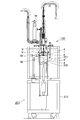
- FIG. 1 is a front view showing an example of a one-component cryogenic fine solid particle continuous production apparatus 100 (fine particle production apparatus) according to an embodiment of the present invention.
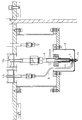
- FIG. 2 is a diagram illustrating an example of a main part of the fine particle generation apparatus 100.
- FIG. 3 is an enlarged view of a main part of the fine particle generating apparatus 100 shown in FIG.
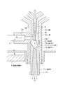
- FIG. 4 is an enlarged cross-sectional view of the vicinity of the nozzle of the fine particle generating apparatus 100.
- the fine particle generating apparatus 100 continuously includes one-component cryogenic fine solid particles using a cryogenic supercooled liquid and a cryogenic gas composed of the same element as the supercooled liquid. To generate. Specifically, the fine particle generating apparatus 100 is provided downstream of the mixing unit 10, the mixing unit 10 that generates a one-component mixed phase flow by mixing a supercooled liquid and a high-speed flow of a cryogenic gas, and the mixing thereof. A Laval nozzle unit 11 that is a nozzle 1 that generates a spray flow including cryogenic fine solid particles from the one-component mixed phase flow generated in the unit 10.
- cryogenic gas nitrogen is employed as the cryogenic gas composed of the same elements as the supercooled liquid nitrogen.
- a two-phase flow (LN 2 -GN 2 ) of supercooled nitrogen liquid (LN 2 ) and cryogenic nitrogen gas (GN 2 ) is discharged from the reduced diameter portion 11b (throat portion) to the injection portion 11c (expanded portion). passes through the opening portion), by solid phase formation based on adiabatic expansion is performed, is generated fine solid nitrogen particles (SN 2), the spray flow is injected containing fine solid nitrogen particles (SN 2) .
- the frame body 210 is provided with a fine particle generating apparatus 100 in the vicinity of the upper portion thereof, and is provided with a movable stage 220 on which a cleaning object 201 is placed at a substantially central portion.
- the movable stage 220 is configured to be movable in the vertical direction with respect to the frame 210 by a control device or a drive device (not shown).
- the movable stage 220 is configured to be movable between an upper limit position a shown in FIG. 1 and a position a ′ below the upper limit position a, and to be fixed at a predetermined position.
- the movable stage 220 is provided with a ceramic heater 2 for heating the cleaning object 201 such as a semiconductor substrate.
- a ceramic heater 2 for heating the cleaning object 201 such as a semiconductor substrate.
- a semiconductor substrate (wafer) with a resist, which is the cleaning target 201 is placed on the movable stage 220.
- the nozzle 1 for ejecting a spray flow containing one-component cryogenic fine solid particles is disposed in the lower part of the fine particle generating apparatus 100.
- the nozzle 1 is configured to inject a spray flow toward the cleaning target 201 on the movable stage 220.
- the nozzle 1 is provided with a liquid nitrogen conduit 3, a nitrogen gas conduit 4, and the like.
- the liquid nitrogen conduit 3 supplies liquid nozzle (LN 2 ) supercooled to a cryogenic temperature to the nozzle 1 from, for example, a liquid nitrogen tank (not shown).
- the liquid nitrogen conduit 3 includes a valve 3a, and the supply amount and pressure of the liquid nitrogen can be controlled by the valve 3a.
- the nitrogen gas conduit 4 supplies cryogenic nitrogen gas (GN 2 ) to the nozzle 1 from a nitrogen gas tank (not shown), for example.
- the nitrogen gas conduit 4 includes a valve 4a, and the supply amount of nitrogen gas (GN 2 ) can be controlled by the valve 4a.
- the nozzle 1 is configured such that all or part of the nozzle 1 is accommodated in the heat insulating portion 5, and the tip portion of the nozzle 1 protrudes outside the heat insulating portion 5.
- the heat insulation part 5 has a vacuum heat insulation structure so as to insulate the nozzle 1 from the outside air.
- the vicinity of the tip of the nozzle 1, the liquid nitrogen conduit 3, and the nitrogen gas conduit 4 is accommodated in the vacuum heat insulating portion 5 to reduce the temperature rise of the nozzle 1, the liquid nitrogen conduit 3, and the nitrogen gas conduit 4. It has a structure to do.
- the movable dish portion 7 is provided below the nozzle 1.
- the movable dish portion 7 is disposed between the nozzle 1 and the cleaning target object 201, spraying from the nozzle 1 to the cleaning target object 201 and cooling air are prevented, and the movable dish portion 7 is disposed at other positions.
- the movable dish portion 7 is configured so that the spray flow from the nozzle 1 collides with the object to be cleaned 201.
- the one-component cryogenic fine solid particle continuous production apparatus 100 of the present embodiment employs a concentric mixing type high-speed two-fluid nozzle.
- the nozzle 1 includes a mixing unit 10, a laval nozzle unit 11, and the like.
- the mixing unit 10 of the nozzle 1 has an inner tube 14 and an outer tube 15 that are concentrically combined.
- the outer diameter of the inner tube 14 is configured to be smaller than the inner diameter of the outer tube 15.
- a gap 45 is formed between the inner tube 14 and the outer tube 15.
- the inner tube 14 communicates with the nitrogen gas conduit 4, and the distal end portion 14 a of the inner tube 14 is formed in a tapered shape.
- a communication portion 15 a communicating with the liquid nitrogen conduit 3 is formed on the side wall of the outer tube 15, and the communication portion 15 a is connected to an opening portion 15 b formed on the inner wall of the outer tube 15.
- the opening 15b is configured to be located near the side surface in the vicinity of the distal end portion 14a of the inner tube 14.
- cryogenic nitrogen gas (GN 2 ) is jetted at high speed from the distal end portion 14 a of the inner tube 14.
- the supercooled liquid (LN 2 ) is supplied to the gap 45 between the inner tube 14 and the outer tube 15 through the liquid nitrogen conduit 3, the communication portion 15a, and the opening portion 15b.
- the supercooled liquid nitrogen (LN 2 ) and the high-speed flow of the cryogenic gas (GN 2 ) are mixed in the mixing section 10 near the downstream side of the distal end portion 14 a of the inner tube 14, and a one-component mixed phase is obtained.
- a stream (LN 2 -GN 2 ) is generated.
- This one-component mixed phase flow (LN 2 -GN 2 ) is introduced into a Laval nozzle unit 11 provided downstream of the mixing unit 10.
- the Laval nozzle portion 11 is provided on the downstream side of the mixing portion 10 and in the vicinity of the distal end portion of the outer tube 15.
- the Laval nozzle part 11 has the introduction part 11a, the diameter reducing part 11b (throat part), and the injection part 11c (expansion part).
- the introduction part 11 a is formed so that the inner diameter on the upstream side is substantially the same as the inner diameter of the outer tube 15 of the mixing part 10.
- a high-speed one-component mixed phase flow (LN 2 -GN 2 ) generated in the mixing unit 10 is introduced into the introduction unit 11a.
- the reduced diameter portion 11b is provided on the downstream side of the introduction portion 11a, and is formed to have an opening cross-sectional area smaller than the opening cross-sectional area of the introduction portion 11a. Specifically, the reduced diameter portion 11b is formed in a shape in which the inner diameter decreases as it approaches the minimum inner diameter portion of the reduced diameter portion 11b from the introduction portion 11a.
- the injection part 11c (expanded part) is provided on the downstream side of the reduced diameter part 11b, and is formed to have an opening sectional area larger than the opening sectional area of the reduced diameter part 11b. Specifically, the injection portion 11c is formed in an expanded shape in which the opening cross-sectional area increases from the reduced diameter portion 11b toward the downstream side.
- the high-pressure / high-speed one-component mixed phase flow has a velocity equal to or lower than the sound velocity, and the velocity increases as the inner diameter decreases from upstream to downstream.
- the one-component mixed phase flow is substantially sonic.
- the opening cross-sectional area increases from the reduced diameter part 11b to the downstream end part of the injection part 11c, the adiabatic expansion of the one-component multiphase flow causes the flow to exceed the speed of sound, and the ice nucleus grows.
- One-component cryogenic fine solid particles are generated, and a spray flow containing the one-component cryogenic fine solid particles is continuously ejected from the ejection unit 11c. Further, the high-pressure / high-speed one-component mixed phase flow is extremely low temperature, and the one-component mixed phase flow adiabatically expands from the reduced diameter portion 11b of the Laval nozzle portion 11 to the downstream end portion of the injection portion 11c. Becomes a speed exceeding the speed of sound, and the temperature is significantly lowered as compared with the introduction part 11a, and the generation of one-component cryogenic fine solid particles is promoted.
- the inner diameter of the outer tube 15 of the mixing unit 10 described above is about 2.5 mm
- the outer diameter of the inner tube 14 is about 1.4 mm
- the inner diameter of the inner tube 14 is about 0.5 mm
- the introduction portion 11a of the Laval nozzle unit 11 The inner diameter of the upstream end portion is about 2.5 mm
- the inner diameter of the reduced diameter portion 11b is about 1.0 mm
- the inner diameter of the tip portion of the injection port of the injection portion 11c is about 2.2 mm.
- Each size of the mixing part 10 and the Laval nozzle part 11 is not restricted to the said form, It is preferable to set suitably.
- the one-component cryogenic fine solid particle continuous generation apparatus 100 includes the ultrasonic transducer 6.
- the ultrasonic transducer 6 applies ultrasonic waves to the Laval nozzle unit 11 as shown in FIGS.
- the ultrasonic transducer 6 applies ultrasonic waves to the Laval nozzle unit 11 as shown in FIGS.
- cavitation is generated in the one-component mixed phase flow in the Laval nozzle part 11, and ice of one-component cryogenic fine solid particles (SN 2 particles) is generated.
- Nucleation can be promoted, and refinement of a substantially spherical one-component cryogenic fine solid particle (SN 2 particle) having a fine uniform particle diameter can be promoted.
- Cavitation is a physical phenomenon in which bubbles are generated and disappeared in a short time due to a pressure difference in a fluid.
- a short-lived high-temperature, high-pressure local field hot spot
- the refined SN 2 particles are formed in a fine substantially spherical shape.
- the ultrasonic transducer 6 includes an ultrasonic vibration generation unit 6a and an ultrasonic transmission unit 6b.
- the ultrasonic vibration generation unit 6a generates ultrasonic waves having a specified frequency and a specified amplitude under the control of a control device (not shown).
- the ultrasonic transmission unit 6 b is configured by a substantially rod-shaped metal member, and transmits the ultrasonic wave generated by the ultrasonic vibration generation unit 6 a to the Laval nozzle unit 11.
- the ultrasonic wave applied from the ultrasonic transducer 6 to the Laval nozzle unit 11 has, for example, a frequency of about 30 kHz to 2 MHz and an amplitude of about 10 ⁇ m to 50 ⁇ m, preferably a frequency of about 40 kHz to 950 kHz and an amplitude. It is about 20 ⁇ m to 40 ⁇ m, and optimally, 45 kHz and an amplitude of about 30 ⁇ m.
- the frequency and amplitude of the ultrasonic wave applied to the Laval nozzle unit 11 are appropriately set according to the particle size, number, etc. of the one-component cryogenic fine solid particles generated by the Laval nozzle unit 11.
- ultrasonic waves applied from the ultrasonic transducer 6 to the Laval nozzle unit 11 are ultrasonic waves having a high frequency (megasonic) of about 1 MHz to several tens of MHz, or several tens of MHz to several hundreds of MHz, for example, ice nuclei Production and atomization promoting properties are further improved.
- the position where the ultrasonic wave generated by the ultrasonic transducer 6 is applied is preferably near the position where ice nucleation of one-component cryogenic fine solid particles of the Laval nozzle unit 11 is performed. A position slightly downstream from the diameter portion 11b is preferable. Further, the position where the ultrasonic wave generated by the ultrasonic transducer 6 is applied may be an arbitrary position of the injection portion 11c on the downstream side from the reduced diameter portion 11b of the Laval nozzle portion 11, or in the entire Laval nozzle portion 11. It may also be set as appropriate according to the particle diameter, the number, etc. of the one-component cryogenic fine solid particles produced by the Laval nozzle unit 11.
- the ultrasonic transducer 6 may apply ultrasonic waves directly or indirectly to the Laval nozzle unit 11 or may apply the ultrasonic wave to the Laval nozzle unit 11 from within the heat insulating unit 5 as a vacuum heat insulating unit.
- Cryogenic supercooled liquid nitrogen (LN 2 ) is introduced from a liquid nitrogen tank (not shown) into the mixing unit 10 in the outer tube 15 through the liquid nitrogen conduit 3, the communicating portion 15a of the outer tube 15, and the opening 15b.
- the High-pressure and high-speed cryogenic nitrogen gas (LN 2 ) is introduced from a nitrogen gas tank (not shown) into the mixing unit 10 through the nitrogen gas conduit 4 and the inner tube 14.
- the pressure of the cryogenic nitrogen gas (LN 2 ) is, for example, about 0.1 MPa to 1.0 MPa, and in this embodiment is about 0.4 MPa.
- the pressure of the cryogenic nitrogen gas (LN 2 ) may be about 0.5 MPa to 1000 MPa or about 1.0 to 10 MPa.
- high-pressure and high-speed cryogenic nitrogen gas (GN 2 ) is jetted at a high speed from the distal end portion 14 a of the inner tube 14, and supercooled liquid (LN 2 ) is discharged from the inner tube 14. It is introduced into the mixing unit 10 through the gap 45 between the outer tubes 15, and in the mixing unit 10, the supercooled liquid nitrogen (LN 2 ) and the high-speed flow of cryogenic gas (GN 2 ) are mixed to form one component. A multiphase flow (LN 2 -GN 2 ) is generated (first step).
- the high-pressure, high-speed, low-temperature, one-component mixed phase flow (LN 2 -GN 2 ) generated in the mixing unit 10 is introduced into the introduction unit 11a of the Laval nozzle unit 11, and at the minimum inner diameter part of the reduced diameter unit 11b.
- the one-component multiphase flow becomes substantially sonic velocity, and the flow crosses the sonic velocity due to adiabatic expansion of the one-component multiphase flow as the opening cross-sectional area increases from the reduced diameter portion 11b to the downstream end portion of the injection portion 11c.
- the one-component multiphase flow adiabatically expands in a state exceeding the speed of sound, and a spray flow containing one-component cryogenic fine solid particles (SN 2 particles) is continuously generated (second). Step).
- ultrasonic waves about 45 kHz, amplitude of about 30 ⁇ m
- cavitation is generated in the one-component mixed phase flow in the Laval nozzle unit 11
- one-component cryogenic temperature is generated.
- Formation of ice nuclei of fine solid particles (SN 2 particles) can be promoted, and miniaturization of one-component cryogenic fine solid particles (SN 2 particles) having a substantially uniform spherical particle shape can be promoted.
- FIG. 5 shows a fine solid produced by a cryogenic nitrogen gas (GN 2 ) and supercooled liquid nitrogen (LN 2 ) by the one-component cryogenic fine solid particle continuous production apparatus 100 according to an embodiment of the present invention.
- the cooling heat flux value q p and the cooling heat flux value q l of liquid nitrogen (LN 2 ) are shown.
- the vertical axis represents the cooling heat flux value [W / m 2 ]
- the horizontal axis represents the dimensionless time t * .
- the cooling heat flux value q p and the cooling heat flux value q n2 rise more rapidly than the cooling heat flux value q l and reach the maximum cooling heat flux value in a short time. It was found that the maximum cooling heat flux value q n2 was the largest among the maximum values of the respective cooling heat flux values. Further, it was found that the cooling heat flux value decay rate was the largest for the cooling heat flux value q l and the smallest for the cooling heat flux value q n2 .
- Attenuation rate of the cooling heat flow flux value q n2 is smaller than the attenuation rate of the cooling heat flow flux value q p, and the cooling heat flow flux value maximum cooling heat flow maximum cooling heat flux value is other q n2 flux value q p, q
- the reason why it is larger than l is that in the spray flow containing fine solid nitrogen particles (SN 2 particles) generated by the above-mentioned cryogenic nitrogen gas (GN 2 ) and supercooled liquid nitrogen (LN 2 ).
- FIG. 6 is a diagram showing an example of a spray collision pressure value of a one-component cryogenic fine solid nitrogen particle (SN 2 ) and a spray collision pressure value by simulation.
- the horizontal axis (x axis) represents the dimensionless time t *
- the vertical axis (y axis) represents the pressure p * obtained by making the collision pressure dimensionless.
- one-component cryogenic fine solid nitrogen particles (SN 2 particles) are caused to collide with a piezoelectric piezoelectric pressure sensor, and the spray collision pressure value of the SN 2 particles is indicated by a dotted line.
- the pressure of the nitrogen gas (GN 2 ) tank was set to 0.4 MPa, and the pressure of the liquid nitrogen (LN 2 ) tank was set to 0.2 MPa.
- the collision pressure value obtained by single particle collision numerical calculation (CFD) is shown by a solid line.
- the collision pressure p * increased rapidly and then decreased.
- the numerical calculation result shows that the collision pressure p * tends to rise and decrease immediately after the collision.
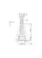
- FIG. 7 is a diagram illustrating an example of the nozzle 1 of the one-component cryogenic fine solid particle continuous generation apparatus 100 including the spiral nozzle 18 at the tip of the Laval nozzle portion.
- a spiral nozzle 18 as shown in Japanese Patent Application Laid-Open No. 2011-171691 is provided at the tip of the Laval nozzle portion 11 of the nozzle 1.
- SN 2 particles one-component cryogenic fine solid nitrogen particles
- PIA Particle Image Analyzer optical measurement system that measures particle size distribution and number density distribution by Direct-Imaging Techniques.
- PIA for example, as shown in FIG. 7, in a defined region CR (Control region), SN 2 particles flying are magnified using a microscope lens and the particle size is analyzed by image analysis. And measure the speed.
- a two-color laser for example, a dual pulse YAG laser, a dye laser for depth of field check, a high-resolution color camera for PIA, PIA image analysis software, or the like
- a high-load distributed computing (Grid Computing) method based on massively parallel computation using a cluster-type high-speed workstation, and the atomization characteristics of the nozzle, for example, the particle size distribution
- the number density distribution, flow velocity / temperature distribution, etc. can be appropriately and quantitatively evaluated.
- a PTV (Particle Tracking Velocimetry) algorithm can be used for quantifying the particle velocity.
- the PTV algorithm to be used considers a distribution pattern of a particle image group composed of a target particle image and a particle image in the vicinity thereof, and performs particle tracking using the similarity.
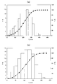
- FIG. 8 is a diagram illustrating an example of a particle size distribution of the one-component cryogenic fine solid particles generated by the one-component cryogenic fine solid particle continuous production apparatus 100 according to the embodiment of the present invention.
- FIG. 8A is a diagram illustrating an example in which ultrasonic waves are not applied to the Laval nozzle unit 11
- FIG. 8B is an example in which ultrasonic waves from an ultrasonic transducer are applied to the Laval nozzle unit 11.
- FIG. 7 the analysis by the PIA-PTV was performed in a specified region (horizontal 0.92 mm, vertical 0.7 mm) as a visual field from a position below 4.5 mm from just below the nozzle hole.
- the horizontal axis (x axis) represents the particle diameter d p [ ⁇ m]
- the left vertical axis (y 1 axis) represents the frequency f f [%]
- the right the vertical axis (y 2 axis) shows the cumulative f a [%].
- the average particle size was reduced by about 2.5% in the case where the ultrasonic transducer was installed in the nozzle 1 (ULA) compared to the case where no ultrasonic wave was applied (non-ULA). Specifically, when the ultrasonic wave by the ultrasonic vibrator is not applied to the Laval nozzle part 11 (non-ULA), the average particle diameter is 4.1 ⁇ m, and the ultrasonic wave by the ultrasonic vibrator is applied to the Laval nozzle part 11 (ULA), the average particle size was 3.9 ⁇ m.
- FIG. 9 is a diagram showing an example of the particle velocity distribution of the one-component cryogenic fine solid particles generated by the one-component cryogenic fine solid particle continuous production apparatus 100 according to the embodiment of the present invention.
- FIG. 9A shows an example in the case where ultrasonic waves from an ultrasonic vibrator are applied to the Laval nozzle unit 11
- FIG. 9B shows an example in which no ultrasonic wave is applied to the Laval nozzle unit 11.
- FIG. 9 (a) and 9 (b) the horizontal axis (x axis) indicates the particle velocity V p [m / s], and the left vertical axis (y 1 axis) indicates the frequency f f [%].
- FIG. 7 shows the cumulative f a [%] to the right vertical axis (y 2 axes).
- the analysis by the PIA-PTV was performed in a specified region (0.92 mm in width, 0.7 mm in length) as a visual field from a position below 4.5 mm from right below the nozzle hole.
- the particle velocity in the case of ULA is small compared to the case of non-ULA.
- the SN 2 particles produced by the one-component method (LN 2 -GN 2 ) are relatively dilute, have a small particle size, and can easily follow the surrounding fluid. Moreover, since the acceleration by inertia force is difficult to work due to the minute particle diameter, it is considered that the particle velocity is further reduced.
- FIG. 10 is a diagram showing an example of a semiconductor cleaning apparatus 200 employing the one-component cryogenic fine solid particle continuous generation apparatus 100 according to the embodiment of the present invention.
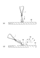
- FIG. 10A shows a case where SN 2 particles collide with the surface of the semiconductor substrate substantially perpendicularly in order to remove the photoresist on the surface of the semiconductor substrate
- FIG. it is a diagram illustrating a case of colliding a SN 2 particles obliquely to the surface.
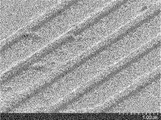
- FIG. 11 is a diagram illustrating an example of the surface of a semiconductor substrate cleaned by a semiconductor cleaning apparatus 200 employing the one-component cryogenic fine solid particle continuous generation apparatus 100 according to an embodiment of the present invention.
- FIG. 11 is an image obtained by photographing the surface of the semiconductor substrate with an electron microscope (SEM: Scanning Electron Microscope).
- the semiconductor cleaning apparatus 200 is a substrate having a wiring 51 and a resist 52 on the surface of the semiconductor substrate 50 as a cleaning object 201.
- a resist: 500 nm / Poly-Si: 150 nm / SiO 2 : 6 nm / Si (before peeling) ) Is heated to about 100 ° C. or higher by the heater 2, in this embodiment to about 277 ° C., and then cryogenic fine solid nitrogen particles (SN 2) ejected from the nozzle 1 of the one-component cryogenic fine solid particle continuous production apparatus 100.
- the resist 52 was peeled off by causing a spray flow containing particles) to collide with the resist 52 on the surface of the semiconductor substrate 50.
- an ultrasonic wave having a frequency of 45 kHz and an amplitude of 330 ⁇ m is added to the nozzle 1 to finely atomize cryogenic nitrogen particles (SN 2 particles) in the spray flow.
- the one-component cryogenic fine solid particle continuous production apparatus 100 produces a one-component cryogenic temperature generated by cryogenic supercooled liquid nitrogen (LN 2 ) and cryogenic nitrogen gas (GN 2 ). It was found that by causing the spray flow containing fine solid particles (SN 2 ) to collide with the resist 52 of the semiconductor substrate 50, the resist 52 can be peeled off and a high cleaning effect can be obtained.
- LN 2 cryogenic supercooled liquid nitrogen
- GN 2 cryogenic nitrogen gas
- cryogenic helium gas GHe
- LN 2 cryogenic supercooled liquid nitrogen
- GN 2 cryogenic nitrogen gas
- This very high cleaning effect is achieved by: (1) a very low temperature, high-speed spray flow containing one-component cryogenic fine solid particles (SN 2 particles) with a high energy, high number density, substantially spherical shape and high hardness. (2) After the semiconductor substrate 50 is heated by the heater 2, the cryogenic fine solid nitrogen particles (SN 2 particles) are caused to collide with the resist of the super high heat flux cooling. Considering factors such as an increase in peeling force due to the thermal contraction effect, and (3) the effect of promoting the formation of ice nuclei and the effect of promoting the formation of fine particles by applying ultrasonic waves to the Laval nozzle portion 11 by the ultrasonic vibrator 6. It is done.
- cryogenic micro solid particles SN 2 particles
- the solid (5) cryogenic micro solid particles (SN 2 particles) - gas from the liquid phase change Resist stripping due to body expansion / diffusion effect based on vapor phase change to phase
- the particle number density of the cryogenic fine solid nitrogen particles (SN 2 particles) is increased, the particle speed is increased, etc.
- the cleaning effect resist removal effect
- SN 2 particles may collide with the surface of the semiconductor substrate 50 substantially perpendicularly.
- the SN 2 particles may be caused to collide obliquely with the surface of the semiconductor substrate 50.
- the collision angle may be appropriately set according to each condition so that the cleaning effect on the cleaning target is optimized.
- a completely chemical-free / pure-free type dry ashing-less cleaning apparatus is provided. Can do.
- on the surface of an object to be cleaned such as a semiconductor substrate (wafer), for example, about 30 to 50 nm. It is possible to satisfactorily perform cleaning with a minute size.
- a high cleaning effect can be obtained for a semiconductor substrate on which a fine wiring pattern such as a next generation type three-dimensional gate structure is formed.
- nitrogen (N 2 ) is an inert gas, the cleaning apparatus 200 can clean the object to be cleaned with almost no charging damage. For this reason, there is little damage to the new Low-k material.
- the one-component cryogenic fine solid particle continuous production apparatus 100 includes supercooled liquid nitrogen (LN 2 ) as a cryogenic supercooled liquid, One-component cryogenic fine solid particles are continuously generated by cryogenic nitrogen gas (GN 2 ) as a cryogenic gas composed of the same elements as the supercooled liquid.
- the one-component cryogenic fine solid particle continuous generation apparatus 100 mixes a supercooled liquid and a high-speed flow of a cryogenic gas to generate a one-component mixed phase flow, and the downstream of the mixing unit 10.
- a Laval nozzle unit 11 that generates a spray flow including cryogenic fine solid particles from the one-component mixed phase flow generated in the mixing unit 10.
- the Laval nozzle unit 11 includes an introduction part 11a that introduces a one-component mixed phase flow generated by the mixing part 10, and a reduced diameter of an opening cross-sectional area that is provided downstream of the introduction part 11a and is smaller than the opening cross-sectional area of the introduction part 11a.
- generation apparatus 100 carries out the adiabatic expansion of the one component multiphase flow in the state exceeding the speed of sound in the injection part 11c, and continues the spray flow containing a one component cryogenic fine solid particle. And generate. In this manner, since the spray flow including the one-component cryogenic fine solid particles can be continuously generated in the injection unit 11c, without using cryogenic helium as a cryogen, with a simple configuration and inexpensively, It is possible to provide a one-component cryogenic fine solid particle continuous production apparatus 100 capable of continuously producing one-component cryogenic fine solid particles.
- the one-component cryogenic fine solid particle continuous generation apparatus 100 includes an ultrasonic transducer 6 that applies ultrasonic waves to the Laval nozzle unit 11.
- an ultrasonic transducer 6 that applies ultrasonic waves to the Laval nozzle unit 11.
- cavitation is generated in the one-component mixed phase flow in the Laval nozzle unit 11, and ice of one-component cryogenic fine solid particles (SN 2 particles) is generated.
- Nucleation can be promoted, and refinement of a substantially spherical one-component cryogenic fine solid particle (SN 2 particle) having a fine uniform particle diameter can be promoted.
- generation apparatus 100 which concerns on embodiment of this invention has the heat insulation part 5 which carries out the vacuum insulation of all or one part of the Laval nozzle part 11 with respect to external air. Specifically, the vicinity of the tip of the nozzle 1, the liquid nitrogen conduit 3, and the nitrogen gas conduit 4 is accommodated in the vacuum heat insulating portion 5, and the temperature rise of the nozzle 1, the liquid nitrogen conduit 3, and the nitrogen gas conduit 4 is reduced. It has a structure. For this reason, one-component cryogenic fine solid particles are continuously generated with a simple structure and capable of jetting a high-speed spray flow containing the one-component cryogenic fine solid particles stably from the Laval nozzle portion 11 of the nozzle 1 for a relatively long time. An apparatus 100 can be provided.
- the one-component cryogenic fine solid particle continuous production apparatus 100 may include a spiral nozzle 18 at the tip of the Laval nozzle unit 11.
- the spiral nozzle 18 By providing the spiral nozzle 18 at the tip of the Laval nozzle unit 11, the one-component cryogenic fine solid particles (SN 2 ) can be further refined.
- the cleaning apparatus (semiconductor cleaning apparatus 200) employing the one-component cryogenic fine solid particle continuous generation apparatus 100 according to the embodiment of the present invention is, for example, a cleaning target (semiconductor substrate) placed on the movable stage 220 or the like.
- the surface of the object to be cleaned (semiconductor substrate, etc.) is cleaned by colliding the surface with a high-speed spray flow containing the one-component cryogenic fine solid particles generated by the one-component cryogenic fine solid particle continuous generation apparatus 100.
- Cleaning means (Laval nozzle portion 11 or the like).
- cryogenic fine solid produced by cryogenic supercooled liquid nitrogen (LN 2 ) and cryogenic nitrogen gas (GN 2 ) without using cryogenic helium gas (GHe) as a cryogen.
- the semiconductor cleaning apparatus 200 that can obtain a high cleaning effect can be provided by spraying the spray flow containing the particles (SN 2 ) onto the object to be cleaned.
- the cleaning apparatus 200 according to the present invention can perform cleaning easily and inexpensively without using cryogenic helium gas. Further, after using cryogenic helium gas for cleaning a semiconductor wafer, helium and nitrogen are used. There is no need to separate.
- the cleaning apparatus (semiconductor cleaning apparatus 200) employing the one-component cryogenic fine solid particle continuous generation apparatus 100 is a one-component cryogenic fine solid which is a micro-nano solid particle having a flow rate on the order of 100 m / s. Because it uses the high-speed thermodynamic collision characteristics of particles (SN 2 particles) and the highly functional heat flow characteristics of cryogenic particle single-particle flow, complete chemical free, pure free type, dry type resist stripping and cleaning are performed. be able to.
- the one-component cryogenic fine solid particle continuous production method 100 uses a supercooled liquid nitrogen (LN 2) as a supercooled liquid by the mixing unit 10. ) And a high-speed flow of cryogenic nitrogen gas (GN 2 ) as a cryogenic gas to generate a one-component mixed phase flow (LN 2 -GN 2 ), and a one-component mixed phase flow ( LN 2 -GN 2 ) is introduced, and the one-component multiphase flow (LN 2 -GN 2 ) is adiabatically expanded in the injection portion 11c of the Laval nozzle portion 11 in a state exceeding the speed of sound, thereby producing a one-component cryogenic fine solid.
- LN 2 supercooled liquid nitrogen
- GN 2 high-speed flow of cryogenic nitrogen gas
- LN 2 -GN 2 a high-speed flow of cryogenic nitrogen gas
- LN 2 -GN 2 one-component mixed phase flow
- LN 2 -GN 2 one-component multiphase flow
- the nitrogen (N 2) one component cryogenic fine solid particles continuously generating apparatus 100 using the may not in this form.
- hydrogen (H 2 ), oxygen (O 2 ), argon (Ar), or the like may be employed.
- a one-component mixed phase flow of cryogenic supercooled liquid hydrogen (GH 2 ) and cryogenic hydrogen gas (LH 2 ) is introduced into the Laval nozzle at a high speed, and the Laval nozzle is injected.
- the one-component multiphase flow is adiabatically expanded in a state exceeding the speed of sound (the speed of sound of the multiphase flow) to continuously generate a spray flow containing one-component cryogenic fine solid particles.
- a one-component mixed phase flow of supercooled liquid oxygen (GO 2 ) and cryogenic oxygen gas (LO 2 ) at a low temperature is introduced into the Laval nozzle at a high speed, and injected into the injection part of the Laval nozzle.
- the one-component multiphase flow is adiabatically expanded in a state exceeding the speed of sound (sound speed of the multiphase flow) to continuously generate a spray flow containing one-component cryogenic fine solid particles.
- argon (Ar) When argon (Ar) is used, a one-component mixed phase flow of supercooled liquid argon and cryogenic argon gas at a low temperature is introduced into the Laval nozzle portion at high speed, and the one-component mixed phase flow is sonic ( Adiabatic expansion is performed in a state exceeding the sound velocity of the multiphase flow, and a spray flow containing one-component cryogenic fine solid particles is continuously generated.
- the cryogenic temperature is a temperature lower than a general low temperature (0 ° C.) and a temperature equal to or lower than the boiling point at a standard pressure such as nitrogen, hydrogen, helium, or argon.
- a standard pressure such as nitrogen, hydrogen, helium, or argon.
- nitrogen (N 2 ) the temperature is about 77.36 K ( ⁇ 195.79 ° C.), which is the boiling point of nitrogen at standard pressure
- hydrogen (H 2 ) is used.
- the temperature is about 20.28 K ( ⁇ 252.87 ° C.) or less, which is the boiling point of hydrogen at the standard pressure
- oxygen (O 2 ) oxygen
- the boiling point of oxygen at the standard pressure is 90.2 K.
- the temperature is about ( ⁇ 182.96 ° C.) or less, and when argon (Ar) is used, the temperature is about 83.80 K ( ⁇ 189.35 ° C.) or less.
- a cryogenic supercooled liquid is used.
- the present invention is not limited to this mode.
- a cryogenic liquid that is not in a supercooled state may be used.
- a cryogenic supercooled liquid it is possible to easily produce one-component cryogenic fine solid particles in a short time.
- Appendix 1 A one-component cryogenic fine solid particle continuous generator that continuously produces one-component cryogenic fine solid particles from a cryogenic supercooled liquid and a cryogenic gas composed of the same element as the supercooled liquid.
- a mixing unit that mixes the supercooled liquid and a high-speed flow of the cryogenic gas to generate a one-component mixed-phase flow
- a Laval nozzle unit that is provided downstream of the mixing unit and generates a spray flow containing cryogenic fine solid particles from the one-component mixed phase flow generated in the mixing unit,
- the Laval nozzle part introduces the one-component mixed phase flow generated in the mixing part, and
- a reduced diameter portion having an opening cross-sectional area smaller than the opening cross-sectional area of the introduction portion provided on the downstream side of the introduction portion;
- An injection portion provided on the downstream side of the reduced diameter portion, formed in an opening cross-sectional area larger than the opening cross-sectional area than the reduced diameter portion, and having a shape expanded toward the downstream side,
- the one-component mixed phase flow is adiabatically expanded in a state exceeding the speed of sound, and a spray flow containing one-component cryogenic fine solid particles is continuously generated.
- Solid particle continuous generator [Appendix 2] The one-component cryogenic fine solid particle continuous generation apparatus according to appendix 1, further comprising an ultrasonic transducer that applies ultrasonic waves to the Laval nozzle portion. [Appendix 3] The one-component cryogenic fine solid particle continuous production apparatus according to appendix 1 or appendix 2, wherein the laval nozzle unit includes a heat insulation part that thermally insulates all or part of the Laval nozzle part from outside air. [Appendix 4] 4. The one-component cryogenic fine solid particle continuous production apparatus according to any one of appendix 1 to appendix 3, wherein a spiral nozzle is provided at a tip of the laval nozzle portion.
- Appendix 5 A high-speed spray flow containing the one-component cryogenic fine solid particles generated by the one-component cryogenic fine solid particle continuous production apparatus according to any one of appendix 1 to appendix 4 is caused to collide with the surface of a semiconductor substrate, thereby the semiconductor A semiconductor cleaning apparatus comprising a cleaning means for cleaning the surface of a substrate.
- Appendix 6 A one-component cryogenic fine solid particle continuous production apparatus for continuously producing one-component cryogenic fine solid particles by using a cryogenic supercooled liquid and a cryogenic gas composed of the same element as the supercooled liquid.
- the one-component cryogenic fine solid particle continuous production apparatus comprises a mixing unit that produces a one-component mixed phase flow by mixing the supercooled liquid and a high-speed flow of the cryogenic gas; A Laval nozzle unit that is provided downstream of the mixing unit and generates a spray flow containing cryogenic fine solid particles from the one-component mixed phase flow generated in the mixing unit, The Laval nozzle part introduces the one-component mixed phase flow generated in the mixing part, and A reduced diameter portion having an opening cross-sectional area smaller than the opening cross-sectional area of the introduction portion provided on the downstream side of the introduction portion; An injection portion provided on the downstream side of the reduced diameter portion, formed in an opening cross-sectional area larger than the opening cross-sectional area than the reduced diameter portion, and having a shape expanded toward the downstream side, A step of mixing the supercooled liquid with the high-speed flow of the cryogenic gas to generate a one-component mixed-phase flow by the mixing unit; The one-component mixed
Landscapes
- Engineering & Computer Science (AREA)
- Mechanical Engineering (AREA)
- Cleaning Or Drying Semiconductors (AREA)
- Exposure Of Semiconductors, Excluding Electron Or Ion Beam Exposure (AREA)
Abstract
寒剤として極低温ヘリウムを用いることなく、簡単な構成で、安価に、一成分で極低温の微細固体粒子を連続生成可能な一成分極低温微細固体粒子連続生成装置を提供する。 一成分極低温微細固体粒子連続生成装置は、極低温の過冷却液体と、その過冷却液体と同一の元素で構成される極低温気体の高速流とを混合して一成分混相流を生成する混合部10と、混合部10の下流に設けられ、その混合部10で生成された一成分混相流から極低温微細固体粒子を含む噴霧流を生成するラバルノズル部11とを有する。ラバルノズル部11は導入部11aと、導入部11aの開口断面積よりも小さい開口断面積の縮径部11bと、縮径部11bよりも大きい開口断面積で且つ下流側に拡開形状の噴射部11cとを有する。噴射部11cにて一成分混相流を音速を超えた状態で断熱膨張させて、一成分極低温微細固体粒子を含む噴霧流を連続して生成する。
Description
本発明は、一成分極低温微細固体粒子連続生成装置、および、その一成分極低温微細固体粒子連続生成方法に関する。
半導体洗浄に関して、一般的に、アンモニア過酸化水素水を用いたウェット・洗浄プロセスが知られている。近年の高集積デバイスに対しては、このようなエッチングによるリフトオフを用いた洗浄法は適用限界に近づきつつある。
このような洗浄法とは異なる、アンモニア過酸化水素水などを用いない半導体ウエハ洗浄方法が知られている(例えば、特許文献1)。詳細には、この特許文献1に記載の洗浄方法は、過冷却液体窒素と、寒剤としての極低温のヘリウムガスの2成分をノズル内で混合することで、極低温マイクロ・ナノソリッド噴霧流体を生成し、そのマイクロ・ナノソリッド噴霧流体を半導体ウエハ表面上のレジストに衝突させて、レジストの剥離・除去を行う。
このような洗浄法とは異なる、アンモニア過酸化水素水などを用いない半導体ウエハ洗浄方法が知られている(例えば、特許文献1)。詳細には、この特許文献1に記載の洗浄方法は、過冷却液体窒素と、寒剤としての極低温のヘリウムガスの2成分をノズル内で混合することで、極低温マイクロ・ナノソリッド噴霧流体を生成し、そのマイクロ・ナノソリッド噴霧流体を半導体ウエハ表面上のレジストに衝突させて、レジストの剥離・除去を行う。
特許文献1に記載された半導体ウエハ洗浄法では、寒剤として極低温のヘリウムガスを使用している。しかしながら、この極低温のヘリウムガスを入手するのが困難な場合がある、極低温のヘリウムガスは比較的高価である、半導体ウエハの洗浄に極低温のヘリウムガスを使用した後、ヘリウムと窒素を分離することを要する、などの問題がある。
このため、寒剤として極低温のヘリウムガスを用いることなく、極低温の微細固体粒子を連続して生成する装置が望まれている。
このため、寒剤として極低温のヘリウムガスを用いることなく、極低温の微細固体粒子を連続して生成する装置が望まれている。
本発明は、上述した問題に鑑みてなされたもので、寒剤として極低温のヘリウムガスを使用することなく、簡単な構成で、安価に、一成分で極低温の微細固体粒子を連続して生成することができる一成分極低温微細固体粒子連続生成装置、および、その一成分極低温微細固体粒子連続生成装置の一成分極低温微細固体粒子連続生成方法、などを提供することを目的とする。
本発明の一成分極低温微細固体粒子連続生成装置は、極低温の過冷却液体と、該過冷却液体と同一の元素で構成される極低温気体とにより、一成分極低温微細固体粒子を連続して生成する一成分極低温微細固体粒子連続生成装置であって、前記過冷却液体と、前記極低温気体の高速流とを混合して一成分混相流を生成する混合部と、混合部の下流に設けられ、該混合部で生成された前記一成分混相流から極低温微細固体粒子を含む噴霧流を生成するラバルノズル部と、を有し、前記ラバルノズル部は、前記混合部で生成された前記一成分混相流を導入する導入部と、前記導入部の下流側に設けられ該導入部の開口断面積よりも小さい開口断面積の縮径部と、前記縮径部の下流側に設けられ該縮径部より開口断面積よりも大きい開口断面積に形成され、且つ、下流側に向かって拡開した形状の噴射部と、を有し、前記噴射部にて、前記一成分混相流を音速を超えた状態で断熱膨張させて、一成分極低温微細固体粒子を含む噴霧流を連続して生成することを特徴とする。
また、本発明の一成分極低温微細固体粒子連続生成方法は、上記本発明の一成分極低温微細固体粒子連続生成装置の一成分極低温微細固体粒子連続生成方法であって、混合部により、過冷却液体と、極低温気体の高速流とを混合して一成分混相流を生成するステップと、ラバルノズル部に一成分混相流を導入して、噴射部にて、一成分混相流を音速を超えた状態で断熱膨張させて、一成分極低温微細固体粒子を含む噴霧流を連続して生成するステップと、を有することを特徴とする。
本発明によれば、寒剤として極低温のヘリウムガスを使用することなく、簡単な構成で、安価に、一成分で極低温の微細固体粒子を連続して生成することができる一成分極低温微細固体粒子連続生成装置、および、その一成分極低温微細固体粒子連続生成装置の一成分極低温微細固体粒子の生成方法を提供することができる。
本発明の実施形態に係る一成分極低温微細固体粒子連続生成装置100(マイクロ・ナノソリッド生成装置)を、図面を参照しながら説明する。以下、一成分極低温微細固体粒子連続生成装置100を微細粒子生成装置ともいう。
図1は、本発明の実施形態に係る一成分極低温微細固体粒子連続生成装置100(微細粒子生成装置)の一例を示す正面図である。図2は微細粒子生成装置100の要部の一例を示す図である。図3は図2に示した微細粒子生成装置100の要部の拡大図である。図4は微細粒子生成装置100のノズル付近の拡大断面図である。
本発明の実施形態に係る微細粒子生成装置100は、極低温の過冷却液体と、その過冷却液体と同一の元素で構成される極低温気体とにより、一成分極低温微細固体粒子を連続して生成する。詳細には、微細粒子生成装置100は、過冷却液体と、極低温気体の高速流とを混合して一成分混相流を生成する混合部10と、混合部10の下流に設けられ、その混合部10で生成された一成分混相流から極低温微細固体粒子を含む噴霧流を生成するノズル1であるラバルノズル部11と、を有する。
本実施形態では、過冷却液体として過冷却液体窒素(LN2)を採用し、過冷却液体窒素と同一の元素で構成される極低温気体として極低温気体窒素(GN2)を採用する。
上記ラバルノズル部11では、過冷却窒素液体(LN2)と極低温窒素ガス(GN2)とによる二相流(LN2-GN2)が縮径部11b(スロート部)から噴射部11c(拡開部)を通過して、断熱膨張に基づく固相形成が行われることにより、微細固体窒素粒子(SN2)が生成されて、微細固体窒素粒子(SN2)を含む噴霧流が噴射される。
次に、図1~図4を参照しながら、本発明の実施形態に係る一成分極低温微細固体粒子連続生成装置100(微細粒子生成装置)を採用した半導体洗浄装置200を詳細に説明する。
図1に示したように、枠体210には、その上部付近に微細粒子生成装置100が設けられ、略中央部に洗浄対象物201を載置する可動ステージ220が設けられている。この可動ステージ220は、制御装置や駆動装置(不図示)により、枠体210に対して上下方向に移動自在に構成されている。可動ステージ220は、詳細には、図1に示した上限位置aと、上限位置aよりも下方の位置a’との間を移動自在、且つ、所定位置に固定可能に構成されている。
可動ステージ220には、半導体基板などの洗浄対象物201を加熱するためのセラミックヒータ2が設けられている。可動ステージ220には、例えば、洗浄対象物201であるレジスト付きの半導体基板(ウエハ)などが載置される。
微細粒子生成装置100は、その下部に一成分極低温微細固体粒子を含む噴霧流を噴出するノズル1が配置されている。ノズル1は、可動ステージ220上の洗浄対象物201に向けて噴霧流を噴射するように構成されている。
ノズル1には、液体窒素導管3、窒素ガス導管4などが配設されている。
液体窒素導管3は、例えば、液体窒素タンク(不図示)などから、極低温に過冷却された液体窒素(LN2)をノズル1に供給する。液体窒素導管3は、バルブ3aを備え、そのバルブ3aにより液体窒素の供給量や圧力などを制御可能に構成されている。
液体窒素導管3は、例えば、液体窒素タンク(不図示)などから、極低温に過冷却された液体窒素(LN2)をノズル1に供給する。液体窒素導管3は、バルブ3aを備え、そのバルブ3aにより液体窒素の供給量や圧力などを制御可能に構成されている。
窒素ガス導管4は、例えば、窒素ガスタンク(不図示)などから、極低温の窒素ガス(GN2)をノズル1に供給する。窒素ガス導管4は、バルブ4aを備え、そのバルブ4aにより窒素ガス(GN2)の供給量を制御可能に構成されている。
<断熱部5>
ノズル1は、全部または一部分が断熱部5内に収容され、ノズル1の先端部が断熱部5の外部に突出するように構成されている。本実施形態では、断熱部5は、ノズル1と外気とを断熱するように真空断熱構造となっている。本実施形態では、ノズル1、液体窒素導管3、窒素ガス導管4の先端部付近が真空断熱部5内に収容されており、ノズル1や液体窒素導管3、窒素ガス導管4の温度上昇を低減する構造となっている。
ノズル1は、全部または一部分が断熱部5内に収容され、ノズル1の先端部が断熱部5の外部に突出するように構成されている。本実施形態では、断熱部5は、ノズル1と外気とを断熱するように真空断熱構造となっている。本実施形態では、ノズル1、液体窒素導管3、窒素ガス導管4の先端部付近が真空断熱部5内に収容されており、ノズル1や液体窒素導管3、窒素ガス導管4の温度上昇を低減する構造となっている。
<可動皿部7>
本実施形態では、図2に示したように、ノズル1の下方に、可動皿部7が設けられている。可動皿部7がノズル1と洗浄対象物201の間に配置された場合、ノズル1から洗浄対象物201への噴霧流や冷気の放射を防止し、可動皿部7がそれ以外の位置に配置された場合、ノズル1からの噴霧流が洗浄対象物201に衝突するように、可動皿部7が構成されている。
本実施形態では、図2に示したように、ノズル1の下方に、可動皿部7が設けられている。可動皿部7がノズル1と洗浄対象物201の間に配置された場合、ノズル1から洗浄対象物201への噴霧流や冷気の放射を防止し、可動皿部7がそれ以外の位置に配置された場合、ノズル1からの噴霧流が洗浄対象物201に衝突するように、可動皿部7が構成されている。
図4に示したように、本実施形態の一成分極低温微細固体粒子連続生成装置100は、同心混合型高速二流体ノズルを採用している。ノズル1は、混合部10と、ラバルノズル部11と、などを有する。
<混合部10>
図4に示したように、ノズル1の混合部10は、同心状に組み合わされた内管14と外管15とを有する。内管14の外径は、外管15の内径よりも小さく構成されている。内管14と外管15の間には、隙間45が形成されている。
図4に示したように、ノズル1の混合部10は、同心状に組み合わされた内管14と外管15とを有する。内管14の外径は、外管15の内径よりも小さく構成されている。内管14と外管15の間には、隙間45が形成されている。
内管14は、窒素ガス導管4に連通しており、内管14の先端部14aは、先細り形状に形成されている。
外管15の側壁には、液体窒素導管3に連通する連通部15aが形成され、外管15の内壁に形成された開口部15bに連通部15aが接続されている。この開口部15bは、内管14の先端部14a近傍の側面付近に位置するように構成されている。
外管15の側壁には、液体窒素導管3に連通する連通部15aが形成され、外管15の内壁に形成された開口部15bに連通部15aが接続されている。この開口部15bは、内管14の先端部14a近傍の側面付近に位置するように構成されている。
図4に示したように、高圧、極低温の窒素ガス(GN2)は、内管14の先端部14aから高速に噴射される。過冷却液体(LN2)は、液体窒素導管3、連通部15a、開口部15bを介して、内管14と外管15の間の隙間45に供給される。このため、内管14の先端部14aの下流側付近の混合部10にて、過冷却液体窒素(LN2)と、極低温気体(GN2)の高速流とが混合して、一成分混相流(LN2-GN2)が生成される。
この一成分混相流(LN2-GN2)は、混合部10の下流に設けられたラバルノズル部11に導入される。
この一成分混相流(LN2-GN2)は、混合部10の下流に設けられたラバルノズル部11に導入される。
<ラバルノズル部11>
ラバルノズル部11は、本実施形態では、混合部10の下流側、且つ、外管15の先端部付近に設けられている。詳細には、ラバルノズル部11は、導入部11aと、縮径部11b(スロート部)と、噴射部11c(拡開部)と、を有する。
ラバルノズル部11は、本実施形態では、混合部10の下流側、且つ、外管15の先端部付近に設けられている。詳細には、ラバルノズル部11は、導入部11aと、縮径部11b(スロート部)と、噴射部11c(拡開部)と、を有する。
導入部11aは、上流側の内径が、混合部10の外管15の内径と略同じとなるように形成されている。この導入部11aには、混合部10で生成された高速の一成分混相流(LN2-GN2)が導入される。
縮径部11bは、導入部11aの下流側に設けられ、その導入部11aの開口断面積よりも小さい開口断面積となるように形成されている。詳細には、縮径部11bは、導入部11aから縮径部11bの最小の内径部分に近づくほど、内径が小さくなる形状に形成されている。
噴射部11c(拡開部)は、縮径部11bの下流側に設けられ、その縮径部11bの開口断面積よりも大きい開口断面積に形成されている。詳細には、噴射部11cは、縮径部11bから下流側に向かって開口断面積が大きくなる拡開した形状に形成されている。
導入部11aおよび縮径部11bの最小内径部分より上流の範囲では、高圧・高速の一成分混相流は、音速以下の速度であり、上流から下流へ内径が小さくなるほど速度が増加する。そして、縮径部11bの最小の内径部分では、一成分混相流が略音速となる。
そして、縮径部11bから噴射部11cの下流側先端部にかけて、開口断面積が大きくなるほど、一成分混相流の断熱膨張により、その流れが音速を超えた状態となり、氷核が成長して、一成分極低温微細固体粒子が生成され、一成分極低温微細固体粒子を含む噴霧流が連続して噴射部11cから噴射される。
また、高圧・高速の一成分混相流は極低温となっており、ラバルノズル部11の縮径部11bから噴射部11cの下流側先端部では、一成分混相流が断熱膨張することで、その流れが音速を超えた速度となり、且つ、導入部11aと比較して温度が著しく低下した状態となり、一成分極低温微細固体粒子の生成が促進される。
そして、縮径部11bから噴射部11cの下流側先端部にかけて、開口断面積が大きくなるほど、一成分混相流の断熱膨張により、その流れが音速を超えた状態となり、氷核が成長して、一成分極低温微細固体粒子が生成され、一成分極低温微細固体粒子を含む噴霧流が連続して噴射部11cから噴射される。
また、高圧・高速の一成分混相流は極低温となっており、ラバルノズル部11の縮径部11bから噴射部11cの下流側先端部では、一成分混相流が断熱膨張することで、その流れが音速を超えた速度となり、且つ、導入部11aと比較して温度が著しく低下した状態となり、一成分極低温微細固体粒子の生成が促進される。
例えば、上述した混合部10の外管15の内径は2.5mm程度、内管14の外径は1.4mm程度、内管14の内径は0.5mm程度、ラバルノズル部11の導入部11aの上流側端部の内径は2.5mm程度、縮径部11bの内径は1.0mm程度、噴射部11cの射出口の先端部分の内径は、2.2mm程度である。
混合部10、ラバルノズル部11の各サイズは、上記形態に限られるものではなく、適宜、設定することが好ましい。
混合部10、ラバルノズル部11の各サイズは、上記形態に限られるものではなく、適宜、設定することが好ましい。
<超音波振動子6>
本実施形態では、一成分極低温微細固体粒子連続生成装置100は、超音波振動子6を有する。
超音波振動子6は、図4、図1に示したように、ラバルノズル部11に超音波を印加する。超音波振動子6により生成された超音波をラバルノズル部11に印加することで、ラバルノズル部11内の一成分混相流にキャビテーションを発生させ、一成分極低温微細固体粒子(SN2粒子)の氷核生成を促進し、且つ、微小均一粒子径の略球形状の一成分極低温微細固体粒子(SN2粒子)の微細化を促進することができる。キャビテーションとは、流体の中で、圧力差により短時間に泡の発生と消滅が起きる物理現象である。キャビテーションによる気泡の崩壊時に、短寿命の高温・高圧の局所場(ホットスポット)が形成される。これを利用することにより、SN2粒子の氷核生成の促進、SN2粒子の微細化の促進などを行うことができる。微細化されたSN2粒子は、微細な略球形状に形成されている。
超音波振動子6は、詳細には、超音波振動生成部6aと超音波伝達部6bとを有する。
超音波振動生成部6aは、制御装置(不図示)の制御により、規定の振動数、規定の振幅の超音波を生成する。
超音波伝達部6bは、略棒形状の金属部材で構成され、超音波振動生成部6aで生成された超音波をラバルノズル部11に伝達する。
超音波振動生成部6aは、制御装置(不図示)の制御により、規定の振動数、規定の振幅の超音波を生成する。
超音波伝達部6bは、略棒形状の金属部材で構成され、超音波振動生成部6aで生成された超音波をラバルノズル部11に伝達する。
超音波振動子6からラバルノズル部11に印加される超音波は、具体的には、例えば、振動数30kHz~2MHz程度、振幅10μm~50μm程度であり、好ましくは、振動数40kHz~950kHz程度、振幅20μm~40μm程度であり、最適には、45kHz、振幅30μm程度である。このラバルノズル部11に印加される超音波の振動数や振幅については、ラバルノズル部11で生成される一成分極低温微細固体粒子の粒径、個数などに応じて適宜、設定する。
尚、超音波振動子6からラバルノズル部11に印加される超音波として、例えば1MHz~数10MHz、または、数10MHz~数100MHz程度の高周波数(メガソニック)の超音波を採用した場合、氷核生成や微粒化促進特性がさらに向上する。
尚、超音波振動子6からラバルノズル部11に印加される超音波として、例えば1MHz~数10MHz、または、数10MHz~数100MHz程度の高周波数(メガソニック)の超音波を採用した場合、氷核生成や微粒化促進特性がさらに向上する。
超音波振動子6で生成した超音波を印加する位置は、例えば、ラバルノズル部11の一成分極低温微細固体粒子の氷核形成が行われる位置付近が好ましく、詳細には、ラバルノズル部11の縮径部11bから僅かに下流側の位置が好ましい。また、超音波振動子6で生成した超音波を印加する位置は、ラバルノズル部11の縮径部11bから下流側の噴射部11cの任意の位置であってもよく、また、ラバルノズル部11全体であってもよく、ラバルノズル部11で生成する一成分極低温微細固体粒子の粒径、個数などに応じて適宜、設定してもよい。
また、超音波振動子6は超音波を直接または間接的にラバルノズル部11に印加してもよいし、真空断熱部としての断熱部5内からラバルノズル部11に印加してもよい。
また、超音波振動子6は超音波を直接または間接的にラバルノズル部11に印加してもよいし、真空断熱部としての断熱部5内からラバルノズル部11に印加してもよい。
<一成分極低温微細固体粒子連続生成装置100の動作>
次に、一成分極低温微細固体粒子連続生成装置100の動作を説明する。
次に、一成分極低温微細固体粒子連続生成装置100の動作を説明する。
液体窒素タンク(不図示)から極低温の過冷却液体窒素(LN2)が液体窒素導管3、外管15の連通部15a、開口部15bを介して外管15内の混合部10に導入される。
窒素ガスタンク(不図示)から高圧・高速の極低温の窒素ガス(LN2)が窒素ガス導管4、内管14を介して混合部10に導入される。極低温の窒素ガス(LN2)の圧力は、例えば、0.1MPa~1.0MPa程度であり、本実施形態では0.4MPa程度である。極低温の窒素ガス(LN2)の圧力が高いほど、混合部10での流速が高速となり、好ましい。尚、この極低温の窒素ガス(LN2)の圧力は、0.5MPa~1000MPa程度であってもよいし、1.0~10MPa程度であってもよい。
窒素ガスタンク(不図示)から高圧・高速の極低温の窒素ガス(LN2)が窒素ガス導管4、内管14を介して混合部10に導入される。極低温の窒素ガス(LN2)の圧力は、例えば、0.1MPa~1.0MPa程度であり、本実施形態では0.4MPa程度である。極低温の窒素ガス(LN2)の圧力が高いほど、混合部10での流速が高速となり、好ましい。尚、この極低温の窒素ガス(LN2)の圧力は、0.5MPa~1000MPa程度であってもよいし、1.0~10MPa程度であってもよい。
そして、図4に示したように、高圧・高速の極低温の窒素ガス(GN2)が、内管14の先端部14aから高速に噴射され、過冷却液体(LN2)が内管14と外管15の間の隙間45から混合部10に導入されて、混合部10にて、過冷却液体窒素(LN2)と極低温気体(GN2)の高速流とが混合して、一成分混相流(LN2-GN2)が生成される(第1のステップ)。
そして、混合部10で生成された高圧・高速の極低温の一成分混相流(LN2-GN2)が、ラバルノズル部11の導入部11aに導入され、縮径部11bの最小の内径部分では、一成分混相流が略音速となり、縮径部11bから噴射部11cの下流側先端部にかけて、開口断面積が大きくなるほど、一成分混相流の断熱膨張により、その流れが音速を超えた状態となり、噴射部11cにて、一成分混相流が音速を超えた状態で断熱膨張して、一成分極低温微細固体粒子(SN2粒子)を含む噴霧流が連続して生成される(第2のステップ)。
また、超音波振動子6により生成された超音波(45kHz程度、振幅30μm程度)をラバルノズル部11に印加することで、ラバルノズル部11内の一成分混相流にキャビテーションを発生させ、一成分極低温微細固体粒子(SN2粒子)の氷核生成を促進し、且つ、微小均一粒子径の略球形状の一成分極低温微細固体粒子(SN2粒子)の微細化を促進することができる。
<冷却熱流束値>
図5は、本発明の一実施形態に係る一成分極低温微細固体粒子連続生成装置100により、極低温の窒素ガス(GN2)と過冷却した液体窒素(LN2)とで生成した微細固体窒素粒子(SN2)の冷却熱流束値qn2と、比較例として、極低温のヘリウムガス(GHe)と過冷却した液体窒素(LN2)とにより生成した微細固体窒素粒子(SN2)の冷却熱流束値qpと、液体窒素(LN2)の冷却熱流束値qlとを示す。
図5においては、縦軸に冷却熱流束値〔W/m2〕を示し、横軸に無次元時間t*を示す。
図5は、本発明の一実施形態に係る一成分極低温微細固体粒子連続生成装置100により、極低温の窒素ガス(GN2)と過冷却した液体窒素(LN2)とで生成した微細固体窒素粒子(SN2)の冷却熱流束値qn2と、比較例として、極低温のヘリウムガス(GHe)と過冷却した液体窒素(LN2)とにより生成した微細固体窒素粒子(SN2)の冷却熱流束値qpと、液体窒素(LN2)の冷却熱流束値qlとを示す。
図5においては、縦軸に冷却熱流束値〔W/m2〕を示し、横軸に無次元時間t*を示す。
図5に示したように、冷却熱流束値qpと冷却熱流束値qn2は、冷却熱流束値qlよりも立ち上がりが急峻で、短時間で最大冷却熱流束値に達した。各冷却熱流束値の最大値のうち、最大冷却熱流束値qn2が最も大きいことが分かった。
また、冷却熱流束値の減衰率は、冷却熱流束値qlが最も大きく、冷却熱流束値qn2が最も小さいことが分かった。
また、冷却熱流束値の減衰率は、冷却熱流束値qlが最も大きく、冷却熱流束値qn2が最も小さいことが分かった。
冷却熱流束値qn2の減衰率が、冷却熱流束値qpの減衰率よりも小さく、且つ、冷却熱流束値qn2の最大冷却熱流束値が他の最大冷却熱流束値qp,qlと比較して大きい理由としては、上述した極低温の窒素ガス(GN2)と過冷却状態の液体窒素(LN2)とにより生成した微細固体窒素粒子(SN2粒子)を含む噴霧流中のSN2粒子の数密度が、極低温のヘリウムガス(GHe)と過冷却状態の液体窒素(LN2)とにより生成した微細固体窒素粒子(SN2粒子)を含む噴霧流中のSN2粒子の数密度と比較して増大したためである。
<SN2粒子の衝突圧力>
図6は一成分極低温微細固体窒素粒子(SN2)の噴霧衝突圧力値およびシミュレーションによる噴霧衝突圧力値の一例を示す図である。図6において、横軸(x軸)に無次元時間t*を示し、縦軸(y軸)に衝突圧力を無次元化した圧力p*を示す。
詳細には、一成分極低温微細固体窒素粒子(SN2粒子)をピエゾ圧電型圧力センサに衝突させて、そのSN2粒子の噴霧衝突圧力値を点線で示す。実験において窒素ガス(GN2)タンクの圧力を0.4MPa、液体窒素(LN2)タンクの圧力を0.2MPaに設定した。
シミュレーションとして単一粒子衝突数値計算(CFD)によって得られた衝突圧力値を実線で示す。
図6に示したように、SN2粒子が圧力センサに衝突した直後、衝突圧力p*が急激に増加した後、減少した。また、数値計算結果でも同様に、衝突圧力p*が衝突直後に立ち上がり、減少する傾向を有していることが分かる。
図7は、ラバルノズル部の先端部にスパイラルノズル18を備えた一成分極低温微細固体粒子連続生成装置100のノズル1の一例を示す図である。
図7に示したように、例えば、特開2011-171691号に示したようなスパイラルノズル18を、ノズル1のラバルノズル部11の先端部に設ける。スパイラルノズル18に一成分極低温微細固体窒素粒子(SN2粒子)の高速ジェット流が通過することにより、適度な乱流を生じさせ、SN2粒子をより細粒子化させることができ、且つ、SN2粒子がノズルに付着するのを防止して、連続的にSN2粒子を含む噴霧流を生成することができる。
図7に示したように、例えば、特開2011-171691号に示したようなスパイラルノズル18を、ノズル1のラバルノズル部11の先端部に設ける。スパイラルノズル18に一成分極低温微細固体窒素粒子(SN2粒子)の高速ジェット流が通過することにより、適度な乱流を生じさせ、SN2粒子をより細粒子化させることができ、且つ、SN2粒子がノズルに付着するのを防止して、連続的にSN2粒子を含む噴霧流を生成することができる。
<一成分極低温微細固体粒子(SN2)の粒子径分布および粒子速度分布>
一成分極低温微細固体粒子連続生成装置100により生成された一成分極低温微細固体粒子(SN2)の粒子径分布、粒子速度分布に関しては、粒子の撮影画像の解析、例えば、直接撮影法(Direct-Imaging Techniques)による粒子径分布・数密度分布計測を行う二色レーザーPIA(Particle Image Analyzer)光学計測システムを使用した二次元化可視化画像計測などにより解析できる。PIAでは、例えば、図7に示したように規定領域CR(Control region)にて、飛翔しているSN2粒子を顕微鏡レンズ等を用いて拡大撮影し、粒子像を画像解析することで粒子径と速度を測定する。例えば、二色レーザーPIA光学計測システムでは、二色レーザー、例えば、デュアルパルスYAGレーザー、被写界深度チェック用色素レーザーなど、PIA用高解像度カラーカメラ、PIA画像解析ソフトウェアなどを使用できる。また、数値解析などの解析に、クラスタ型高速ワークステーションを使用した超並列計算による高負荷分散型コンピューティング(Grid Computing)手法を使用することが好ましく、ノズルの微粒化特性、例えば、粒径分布、数密度分布、流速・温度分布等を適切に定量的に評価することができる。
また、粒子速度の定量化には、PTV(Particle Tracking Velocimetry)アルゴリズムを使用することができる。使用するPTVアルゴリズムは、着目粒子像とその近傍の粒子像とから構成される粒子像群の分布パターンを考え、その類似性を利用して粒子追跡(Particle Tracking)を行うものである。
<粒子径分布>
図8は、本発明の実施形態に係る一成分極低温微細固体粒子連続生成装置100により生成される一成分極低温微細固体粒子の粒子径の分布の一例を示す図である。詳細には、図8(a)は超音波をラバルノズル部11に印加しない場合の一例を示す図、図8(b)は超音波振動子による超音波をラバルノズル部11に印加した場合の一例を示す図である。
ここでは、図7に示したように、噴孔直下から4.5mmだけ下方位置から視野としての規定領域(横0.92mm、縦0.7mm)で上記PIA-PTVによる解析を行った。
図8(a)、図8(b)においては、横軸(x軸)に粒子直径dp〔μm〕を示し、左縦軸(y1軸)に頻度ff〔%〕を示し、右縦軸(y2軸)に累積fa〔%〕を示している。
超音波を印加しない場合と比較して、超音波振動子による超音波をラバルノズル部11に加えて微粒化促進させた場合、最小粒子径の占める分布割合が大きいことが分かった。
超音波を印加しない場合(non-ULA)と比較して、超音波振動子をノズル1に設置した場合(ULA)では、平均粒子径が約2.5%程度減少していることが分かった。
詳細には、超音波振動子による超音波をラバルノズル部11に印加させない場合(non-ULA)、平均粒子径は4.1μmであり、超音波振動子による超音波をラバルノズル部11に印加した場合(ULA)、平均粒子径が3.9μmであった。
詳細には、超音波振動子による超音波をラバルノズル部11に印加させない場合(non-ULA)、平均粒子径は4.1μmであり、超音波振動子による超音波をラバルノズル部11に印加した場合(ULA)、平均粒子径が3.9μmであった。
<粒子速度分布>
図9は、本発明の実施形態に係る一成分極低温微細固体粒子連続生成装置100により生成される一成分極低温微細固体粒子の粒子速度分布の一例を示す図である。詳細には図9(a)は超音波振動子による超音波をラバルノズル部11に印加した場合の一例を示す図、図9(b)はラバルノズル部11に超音波を印加しない場合の一例を示す図である。
図9(a)、図9(b)においては、横軸(x軸)に粒子速度Vp〔m/s〕を示し、左縦軸(y1軸)に頻度ff〔%〕を示し、右縦軸(y2軸)に累積fa〔%〕を示している。
同様に、図7に示したように、噴孔直下から4.5mmだけ下方位置から視野としての規定領域(横0.92mm、縦0.7mm)で上記PIA-PTVによる解析を行った。
non-ULAの場合と比較して、ULAの場合の粒子速度は小さいことが分かる。一成分方式(LN2-GN2)によって生成されたSN2粒子は比較的希薄であり、粒子径が小さく、周囲の流体に追従しやすくなるため、粒子速度が減少したと考えられる。また、微小な粒子径により、慣性力による加速が効きにくいので、さらに粒子速度が減少したと考えられる。
<洗浄装置200の動作>
図10は本発明の実施形態に係る一成分極低温微細固体粒子連続生成装置100を採用した半導体洗浄装置200の一例を示す図である。詳細には、図10(a)は半導体基板の表面のフォトレジストを除去するためにSN2粒子を半導体基板の表面に略垂直に衝突させる場合を示す図、図10(b)は半導体基板の表面へSN2粒子を斜めに衝突させる場合を示す図である。図11は、本発明の実施形態に係る一成分極低温微細固体粒子連続生成装置100を採用した半導体洗浄装置200で洗浄された半導体基板の表面の一例を示す図である。詳細には、図11は、電子顕微鏡(SEM:Scanning Electron Microscope)にて半導体基板の表面を撮影した画像である。
図10は本発明の実施形態に係る一成分極低温微細固体粒子連続生成装置100を採用した半導体洗浄装置200の一例を示す図である。詳細には、図10(a)は半導体基板の表面のフォトレジストを除去するためにSN2粒子を半導体基板の表面に略垂直に衝突させる場合を示す図、図10(b)は半導体基板の表面へSN2粒子を斜めに衝突させる場合を示す図である。図11は、本発明の実施形態に係る一成分極低温微細固体粒子連続生成装置100を採用した半導体洗浄装置200で洗浄された半導体基板の表面の一例を示す図である。詳細には、図11は、電子顕微鏡(SEM:Scanning Electron Microscope)にて半導体基板の表面を撮影した画像である。
半導体洗浄装置200は、洗浄対象物201として、半導体基板50の表面に配線51およびレジスト52を有する基体、詳細には、レジスト:500nm/Poly-Si:150nm/SiO2:6nm/Si(剥離前の状態)をヒータ2により約100℃以上、本実施形態では約277℃まで加熱後、一成分極低温微細固体粒子連続生成装置100のノズル1から噴射した極低温の微細固体窒素粒子(SN2粒子)を含む噴霧流を半導体基板50の表面のレジスト52に衝突させることで、レジスト52の剥離を行った。ノズル1には、例えば周波数45kHz、振幅330μmの超音波を付加して、噴霧流中の極低温の窒素粒子(SN2粒子)を細粒化している。
図11に示したように、一成分極低温微細固体粒子連続生成装置100が、極低温の過冷却液体窒素(LN2)と、極低温窒素ガス(GN2)とにより生成した一成分極低温微細固体粒子(SN2)を含む噴霧流を半導体基板50のレジスト52に衝突させることで、レジスト52を剥離することができ高い洗浄効果が得られることが分かった。
つまり、寒剤として極低温のヘリウムガス(GHe)を用いることなく、極低温の過冷却液体窒素(LN2)と、極低温窒素ガス(GN2)とにより生成した一成分極低温微細固体粒子(SN2)を含む噴霧流を、洗浄対象物に噴射することで、非常に高い洗浄効果が得られる。
この非常に高い洗浄効果は、(1)高い数密度、略球形状、高い硬度の一成分極低温微細固体粒子(SN2粒子)を含む極低温の高速の噴霧流を、非常に高いエネルギーで半導体基板50のレジストに衝突させたこと、(2)半導体基板50をヒータ2にて加熱後、極低温微細固体窒素粒子(SN2粒子)を衝突させることにより超高熱流束冷却に基づくレジストの熱収縮効果により剥離力が増大したこと、(3)超音波振動子6による超音波のラバルノズル部11への印加による、氷核形成の促進効果、および、微粒子化促進効果、なども要因として考えられる。また、(4)極低温マイクロソリッド粒子(SN2粒子)の液相変化による液ジェット流によるレジストミキシングによる剥離、(5)極低温マイクロソリッド粒子(SN2粒子)の固-液相変化から気相への蒸気相変化に基づく体膨張・拡散効果によるレジストはく離、(6)半導体基板(ウエハ)近傍に存在する極低温マイクロソリッド粒子が誘起する微小熱対流による剥離レジストの再付着防止機構なども要因として考えられる。
さらに、極低温窒素ガス(GN2)の圧力を上げるなどの処理を行うことにより、極低温微細固体窒素粒子(SN2粒子)の粒子数密度を大きくする、より高い粒子速度とする、などにより、洗浄効果(レジスト除去効果)をさらに向上させることができる。
尚、半導体基板50の表面のフォトレジスト52を除去するために、例えば、図10(a)に示したように、SN2粒子を半導体基板50の表面に略垂直に衝突させてもよいし、図10(b)に示したように、半導体基板50の表面へSN2粒子を斜めに衝突させてもよい。この衝突角度は、各条件に応じて適宜設定することで、洗浄対象物への洗浄効果が最適となるようにしてもよい。
また、本発明の実施形態に係る一成分極低温微細固体粒子連続生成装置100を採用した半導体洗浄装置200によれば、完全ケミカルフリー・純粋フリータイプのドライ型アッシングレスの洗浄装置を提供することができる。
また、本発明の実施形態に係る一成分極低温微細固体粒子連続生成装置100を採用した半導体洗浄装置200によれば、半導体基板(ウエハ)など洗浄対象物の表面において、例えば、30~50nm程度の微小なサイズで良好に洗浄を行うことができる。
また、この洗浄装置200によれば、例えば、次世代型3次元ゲート構造などの微細な配線パターンが形成された半導体基板に対して高い洗浄効果を得ることができる。
また、窒素(N2)は不活性ガスであるので、洗浄装置200によれば、チャージングダメージをほとんど生ずることなく、洗浄対象物に対して洗浄を行うことができる。このため、新Low-k材料へのダメージが少ない。
また、本発明の実施形態に係る一成分極低温微細固体粒子連続生成装置100を採用した半導体洗浄装置200によれば、半導体基板(ウエハ)など洗浄対象物の表面において、例えば、30~50nm程度の微小なサイズで良好に洗浄を行うことができる。
また、この洗浄装置200によれば、例えば、次世代型3次元ゲート構造などの微細な配線パターンが形成された半導体基板に対して高い洗浄効果を得ることができる。
また、窒素(N2)は不活性ガスであるので、洗浄装置200によれば、チャージングダメージをほとんど生ずることなく、洗浄対象物に対して洗浄を行うことができる。このため、新Low-k材料へのダメージが少ない。
以上、説明したように、本発明の実施形態に係る一成分極低温微細固体粒子連続生成装置100(微粒子生成装置)は、極低温の過冷却液体としての過冷却液体窒素(LN2)と、その過冷却液体と同一の元素で構成される極低温気体としての極低温窒素ガス(GN2)とにより、一成分極低温微細固体粒子を連続して生成する。
詳細には、一成分極低温微細固体粒子連続生成装置100は、過冷却液体と、極低温気体の高速流とを混合して一成分混相流を生成する混合部10と、混合部10の下流に設けられ、その混合部10で生成された一成分混相流から極低温微細固体粒子を含む噴霧流を生成するラバルノズル部11と、を有する。このラバルノズル部11は、混合部10で生成された一成分混相流を導入する導入部11aと、導入部11aの下流側に設けられ導入部11aの開口断面積よりも小さい開口断面積の縮径部11b(スロート部)と、縮径部11bの下流側に設けられその縮径部11bより開口断面積よりも大きい開口断面積に形成され、且つ、下流側に向かって拡開した形状の噴射部11cと、を有する。
そして、一成分極低温微細固体粒子連続生成装置100は、噴射部11cにて、一成分混相流を音速を超えた状態で断熱膨張させて、一成分極低温微細固体粒子を含む噴霧流を連続して生成する。
このように、噴射部11cにて、一成分極低温微細固体粒子を含む噴霧流を連続して生成することができるので、寒剤として極低温ヘリウムを用いることなく、簡単な構成で、安価に、一成分で極低温の微細固体粒子を連続生成可能な一成分極低温微細固体粒子連続生成装置100を提供することができる。
また、本発明の実施形態に係る一成分極低温微細固体粒子連続生成装置100は、ラバルノズル部11に超音波を印加する超音波振動子6を有する。この超音波振動子6で生成した超音波をラバルノズル部11に印加することで、ラバルノズル部11内の一成分混相流にキャビテーションを発生させ、一成分極低温微細固体粒子(SN2粒子)の氷核生成を促進し、且つ、微小均一粒子径の略球形状の一成分極低温微細固体粒子(SN2粒子)の微細化を促進することができる。
また、本発明の実施形態に係る一成分極低温微細固体粒子連続生成装置100は、ラバルノズル部11の全部または一部を外気に対して真空断熱する断熱部5を有する。詳細には、ノズル1、液体窒素導管3、窒素ガス導管4の先端部付近が真空断熱部5内に収容されており、ノズル1や液体窒素導管3、窒素ガス導管4の温度上昇を低減した構造となっている。このため簡単な構造で、比較的長時間、安定して一成分極低温微細固体粒子を含む高速噴霧流をノズル1のラバルノズル部11から噴射させることが可能な一成分極低温微細固体粒子連続生成装置100を提供することができる。
また、本発明の実施形態に係る一成分極低温微細固体粒子連続生成装置100は、ラバルノズル部11の全部または一部を外気に対して真空断熱する断熱部5を有する。詳細には、ノズル1、液体窒素導管3、窒素ガス導管4の先端部付近が真空断熱部5内に収容されており、ノズル1や液体窒素導管3、窒素ガス導管4の温度上昇を低減した構造となっている。このため簡単な構造で、比較的長時間、安定して一成分極低温微細固体粒子を含む高速噴霧流をノズル1のラバルノズル部11から噴射させることが可能な一成分極低温微細固体粒子連続生成装置100を提供することができる。
また、本発明の実施形態に係る一成分極低温微細固体粒子連続生成装置100は、ラバルノズル部11の先端部にスパイラルノズル18を備えていてもよい。ラバルノズル部11の先端部にスパイラルノズル18を設けることにより、さらに、一成分極低温微細固体粒子(SN2)を微細化させることができる。
また、本発明の実施形態に係る一成分極低温微細固体粒子連続生成装置100を採用した洗浄装置(半導体洗浄装置200)は、例えば、可動ステージ220などに載置された洗浄対象物(半導体基板など)の表面に、一成分極低温微細固体粒子連続生成装置100で生成した一成分極低温微細固体粒子を含む高速噴霧流を衝突させることで、洗浄対象物(半導体基板など)の表面を洗浄する洗浄手段(ラバルノズル部11など)を有する。
このように、寒剤として極低温のヘリウムガス(GHe)を用いることなく、極低温の過冷却液体窒素(LN2)と、極低温窒素ガス(GN2)とにより生成した一成分極低温微細固体粒子(SN2)を含む噴霧流を、洗浄対象物に噴射することで、高い洗浄効果を得ることができる半導体洗浄装置200を提供することができる。本発明に係る洗浄装置200は、極低温のヘリウムガスを用いずに安価に、簡単に洗浄を行うことができ、さらに、半導体ウエハの洗浄に極低温のヘリウムガスを使用した後、ヘリウムと窒素を分離する必要がない。
また、一成分極低温微細固体粒子連続生成装置100を採用した洗浄装置(半導体洗浄装置200)は、上述したように、流速100m/sオーダのマイクロ・ナノソリッド粒子である一成分極低温微細固体粒子(SN2粒子)による運動力学的高速衝突と、極低温粒1子流の有する高機能熱流動特性を利用しているので、完全ケミカルフリー、純粋フリータイプ、ドライ型レジストはく離・洗浄を行うことができる。
また、一成分極低温微細固体粒子連続生成装置100を採用した洗浄装置(半導体洗浄装置200)は、上述したように、流速100m/sオーダのマイクロ・ナノソリッド粒子である一成分極低温微細固体粒子(SN2粒子)による運動力学的高速衝突と、極低温粒1子流の有する高機能熱流動特性を利用しているので、完全ケミカルフリー、純粋フリータイプ、ドライ型レジストはく離・洗浄を行うことができる。
また、本発明の実施形態に係る一成分極低温微細固体粒子連続生成装置100の一成分極低温微細固体粒子連続生成方法は、混合部10により、過冷却液体としての過冷却液体窒素(LN2)と、極低温気体としての極低温窒素ガス(GN2)の高速流とを混合して一成分混相流(LN2-GN2)を生成するステップと、ラバルノズル部11に一成分混相流(LN2-GN2)を導入して、ラバルノズル部11の噴射部11cにて、一成分混相流(LN2-GN2)を音速を超えた状態で断熱膨張させて、一成分極低温微細固体粒子(SN2)を含む噴霧流を連続して生成するステップと、を有する。
すなわち、寒剤として極低温ヘリウムを用いることなく、簡単に、一成分で極低温の微細固体粒子(SN2)を連続生成可能な一成分極低温微細固体粒子連続生成方法を提供することができる。
すなわち、寒剤として極低温ヘリウムを用いることなく、簡単に、一成分で極低温の微細固体粒子(SN2)を連続生成可能な一成分極低温微細固体粒子連続生成方法を提供することができる。
尚、上記実施形態では、窒素(N2)を用いた一成分極低温微細固体粒子連続生成装置100を示したが、この形態でなくともよい。例えば、水素(H2)、酸素(O2)、アルゴン(Ar)などを採用してもよい。
例えば、水素(H2)を採用した場合、極低温の過冷却液体水素(GH2)と極低温水素ガス(LH2)の一成分混相流を高速にラバルノズル部内に導入し、ラバルノズル部の噴射部にて、一成分混相流を音速(混相流の音速)を超えた状態で断熱膨張させて、一成分極低温微細固体粒子を含む噴霧流を連続して生成する。
酸素(O2)を採用した場合、極低温の過冷却液体酸素(GO2)と極低温酸素ガス(LO2)の一成分混相流を高速にラバルノズル部内に導入し、ラバルノズル部の噴射部にて、一成分混相流を音速(混相流の音速)を超えた状態で断熱膨張させて、一成分極低温微細固体粒子を含む噴霧流を連続して生成する。
アルゴン(Ar)を採用した場合、極低温の過冷却液体アルゴンと極低温アルゴンガスの一成分混相流を高速にラバルノズル部内に導入し、ラバルノズル部の噴射部にて、一成分混相流を音速(混相流の音速)を超えた状態で断熱膨張させて、一成分極低温微細固体粒子を含む噴霧流を連続して生成する。
尚、極低温とは、一般的な低温(0℃)よりも低い温度であり、且つ、窒素、水素、ヘリウム、アルゴンなどの標準気圧での沸点程度以下の温度である。詳細には、例えば、窒素(N2)を用いた場合、標準気圧での窒素の沸点である77.36K(-195.79℃)程度以下の温度であり、水素(H2)を用いた場合、標準気圧での水素の沸点である20.28K(-252.87℃)程度以下の温度であり、酸素(O2)を用いた場合、標準気圧での酸素の沸点である90.2K(-182.96℃)程度以下の温度であり、アルゴン(Ar)を用いた場合、83.80K(-189.35℃)程度以下の温度である。
また、本実施形態では、極低温の過冷却液体を用いたが、この形態に限られるものではなく、例えば、過冷却状態でない、極低温の液体を用いてもよい。尚、極低温の過冷却液体を用いることにより、短時間に、容易に、一成分極低温微細固体粒子を生成することが可能である。
以上、本発明の実施形態について図面を参照して詳述してきたが、具体的な構成はこれらの実施形態に限られるものではなく、本発明の要旨を逸脱しない範囲の設計の変更等があっても本発明に含まれる。
また、上述の各図で示した実施形態は、その目的及び構成等に特に矛盾や問題がない限り、互いの記載内容を組み合わせることが可能である。
また、各図の記載内容はそれぞれ独立した実施形態になり得るものであり、本発明の実施形態は各図を組み合わせた一つの実施形態に限定されるものではない。
また、上述の各図で示した実施形態は、その目的及び構成等に特に矛盾や問題がない限り、互いの記載内容を組み合わせることが可能である。
また、各図の記載内容はそれぞれ独立した実施形態になり得るものであり、本発明の実施形態は各図を組み合わせた一つの実施形態に限定されるものではない。
以上、本発明の実施形態について説明したが、本発明の実施形態の一部または全部は、以下の付記のように記載される。
[付記1]
極低温の過冷却液体と、該過冷却液体と同一の元素で構成される極低温気体とにより、一成分極低温微細固体粒子を連続して生成する一成分極低温微細固体粒子連続生成装置であって、
前記過冷却液体と、前記極低温気体の高速流とを混合して一成分混相流を生成する混合部と、
前記混合部の下流に設けられ、該混合部で生成された前記一成分混相流から極低温微細固体粒子を含む噴霧流を生成するラバルノズル部と、を有し、
前記ラバルノズル部は、前記混合部で生成された前記一成分混相流を導入する導入部と、
前記導入部の下流側に設けられ該導入部の開口断面積よりも小さい開口断面積の縮径部と、
前記縮径部の下流側に設けられ該縮径部より開口断面積よりも大きい開口断面積に形成され、且つ、下流側に向かって拡開した形状の噴射部と、を有し、
前記噴射部にて、前記一成分混相流を音速を超えた状態で断熱膨張させて、一成分極低温微細固体粒子を含む噴霧流を連続して生成することを特徴とする
一成分極低温微細固体粒子連続生成装置。
[付記2]
前記ラバルノズル部に超音波を印加する超音波振動子を有することを特徴とする付記1に記載の一成分極低温微細固体粒子連続生成装置。
[付記3]
前記ラバルノズル部の全部または一部を外気に対して真空断熱する断熱部を有することを特徴とする付記1または付記2に記載の一成分極低温微細固体粒子連続生成装置。
[付記4]
前記ラバルノズル部の先端部にスパイラルノズルが設けられていることを特徴とする付記1から付記3のいずれかに記載の一成分極低温微細固体粒子連続生成装置。
[付記5]
付記1から付記4のいずれかに記載の一成分極低温微細固体粒子連続生成装置により生成した前記一成分極低温微細固体粒子を含む高速噴霧流を、半導体基板の表面に衝突させて、該半導体基板の表面を洗浄する洗浄手段を有することを特徴とする
半導体洗浄装置。
[付記6]
極低温の過冷却液体と、該過冷却液体と同一の元素で構成される極低温気体とにより、一成分極低温微細固体粒子を連続して生成する一成分極低温微細固体粒子連続生成装置の一成分極低温微細固体粒子連続生成方法であって、
前記一成分極低温微細固体粒子連続生成装置は、前記過冷却液体と、前記極低温気体の高速流とを混合して一成分混相流を生成する混合部と、
前記混合部の下流に設けられ、該混合部で生成された前記一成分混相流から極低温微細固体粒子を含む噴霧流を生成するラバルノズル部と、を有し、
前記ラバルノズル部は、前記混合部で生成された前記一成分混相流を導入する導入部と、
前記導入部の下流側に設けられ該導入部の開口断面積よりも小さい開口断面積の縮径部と、
前記縮径部の下流側に設けられ該縮径部より開口断面積よりも大きい開口断面積に形成され、且つ、下流側に向かって拡開した形状の噴射部と、を有し、
前記混合部により、前記過冷却液体と、前記極低温気体の高速流とを混合して一成分混相流を生成するステップと、
前記ラバルノズル部に前記一成分混相流を導入して、前記噴射部にて、前記一成分混相流を音速を超えた状態で断熱膨張させて、一成分極低温微細固体粒子を含む噴霧流を連続して生成するステップと、を有することを特徴とする
一成分極低温微細固体粒子連続生成方法。
1 ノズル
3 液体窒素導管
3a バルブ
4 窒素ガス導管
4a バルブ
5 断熱部(真空断熱部)
6 超音波振動子
6a 超音波振動生成部
6b 超音波伝達部
7 可動皿部
10 混合部
11 ラバルノズル部(ラバール・ノズル)
11a 導入部
11b 縮径部(スロート部)
11c 噴射部(拡開部)
18 スパイラルノズル
45 隙間
50 半導体基板(洗浄対象物)
100 一成分極低温微細固体粒子連続生成装置(微細粒子生成装置)
200 半導体洗浄装置(洗浄装置)
201 洗浄対象物
210 枠体
220 可動ステージ
3 液体窒素導管
3a バルブ
4 窒素ガス導管
4a バルブ
5 断熱部(真空断熱部)
6 超音波振動子
6a 超音波振動生成部
6b 超音波伝達部
7 可動皿部
10 混合部
11 ラバルノズル部(ラバール・ノズル)
11a 導入部
11b 縮径部(スロート部)
11c 噴射部(拡開部)
18 スパイラルノズル
45 隙間
50 半導体基板(洗浄対象物)
100 一成分極低温微細固体粒子連続生成装置(微細粒子生成装置)
200 半導体洗浄装置(洗浄装置)
201 洗浄対象物
210 枠体
220 可動ステージ
Claims (4)
- 極低温の過冷却液体と、該過冷却液体と同一の元素で構成される極低温気体とにより、一成分極低温微細固体粒子を連続して生成する一成分極低温微細固体粒子連続生成装置であって、
前記過冷却液体と、前記極低温気体の高速流とを混合して一成分混相流を生成する混合部と、
前記混合部の下流に設けられ、該混合部で生成された前記一成分混相流から極低温微細固体粒子を含む噴霧流を生成するラバルノズル部と、を有し、
前記ラバルノズル部は、前記混合部で生成された前記一成分混相流を導入する導入部と、
前記導入部の下流側に設けられ該導入部の開口断面積よりも小さい開口断面積の縮径部と、
前記縮径部の下流側に設けられ該縮径部の開口断面積よりも大きい開口断面積に形成され、且つ、下流側に向かって拡開した形状の噴射部と、を有し、
前記噴射部にて、前記一成分混相流を音速を超えた状態で断熱膨張させて、一成分極低温微細固体粒子を含む噴霧流を連続して生成することを特徴とする
一成分極低温微細固体粒子連続生成装置。 - 前記ラバルノズル部に超音波を印加する超音波振動子を有することを特徴とする請求項1に記載の一成分極低温微細固体粒子連続生成装置。
- 請求項1または請求項2に記載の一成分極低温微細固体粒子連続生成装置により生成した前記一成分極低温微細固体粒子を含む高速噴霧流を、半導体基板の表面に衝突させて、該半導体基板の表面を洗浄する洗浄手段を有することを特徴とする
半導体洗浄装置。 - 極低温の過冷却液体と、該過冷却液体と同一の元素で構成される極低温気体とにより、一成分極低温微細固体粒子を連続して生成する一成分極低温微細固体粒子連続生成装置の一成分極低温微細固体粒子連続生成方法であって、
前記一成分極低温微細固体粒子連続生成装置は、前記過冷却液体と、前記極低温気体の高速流とを混合して一成分混相流を生成する混合部と、
前記混合部の下流に設けられ、該混合部で生成された前記一成分混相流から極低温微細固体粒子を含む噴霧流を生成するラバルノズル部と、を有し、
前記ラバルノズル部は、前記混合部で生成された前記一成分混相流を導入する導入部と、
前記導入部の下流側に設けられ該導入部の開口断面積よりも小さい開口断面積の縮径部と、
前記縮径部の下流側に設けられ該縮径部の開口断面積よりも大きい開口断面積に形成され、且つ、下流側に向かって拡開した形状の噴射部と、を有し、
前記混合部により、前記過冷却液体と、前記極低温気体の高速流とを混合して一成分混相流を生成するステップと、
前記ラバルノズル部に前記一成分混相流を導入して、前記噴射部にて、前記一成分混相流を音速を超えた状態で断熱膨張させて、一成分極低温微細固体粒子を含む噴霧流を連続して生成するステップと、を有することを特徴とする
一成分極低温微細固体粒子連続生成方法。
Applications Claiming Priority (2)
| Application Number | Priority Date | Filing Date | Title |
|---|---|---|---|
| JP2013125074A JP6153110B2 (ja) | 2013-06-13 | 2013-06-13 | 一成分極低温微細固体粒子連続生成装置、および、その一成分極低温微細固体粒子連続生成方法 |
| JP2013-125074 | 2013-06-13 |
Publications (1)
| Publication Number | Publication Date |
|---|---|
| WO2014199705A1 true WO2014199705A1 (ja) | 2014-12-18 |
Family
ID=52022011
Family Applications (1)
| Application Number | Title | Priority Date | Filing Date |
|---|---|---|---|
| PCT/JP2014/059940 Ceased WO2014199705A1 (ja) | 2013-06-13 | 2014-04-04 | 一成分極低温微細固体粒子連続生成装置、および、その一成分極低温微細固体粒子連続生成方法 |
Country Status (2)
| Country | Link |
|---|---|
| JP (1) | JP6153110B2 (ja) |
| WO (1) | WO2014199705A1 (ja) |
Cited By (9)
| Publication number | Priority date | Publication date | Assignee | Title |
|---|---|---|---|---|
| WO2016158479A1 (ja) * | 2015-03-27 | 2016-10-06 | 国立大学法人東北大学 | 凍結装置、凍結方法 |
| CN108590512A (zh) * | 2018-03-28 | 2018-09-28 | 中国矿业大学(北京) | 一种可燃冰冷钻进方法和装置 |
| WO2019035920A1 (en) * | 2017-08-18 | 2019-02-21 | Tel Fsi, Inc. | Apparatus for spraying cryogenic fluids |
| US10625280B2 (en) | 2014-10-06 | 2020-04-21 | Tel Fsi, Inc. | Apparatus for spraying cryogenic fluids |
| US10748789B2 (en) | 2014-10-06 | 2020-08-18 | Tel Fsi, Inc. | Systems and methods for treating substrates with cryogenic fluid mixtures |
| CN111751077A (zh) * | 2020-07-10 | 2020-10-09 | 中国空气动力研究与发展中心超高速空气动力研究所 | 一种提高高超声速流场固体粒子跟随性的方法 |
| US10991610B2 (en) | 2014-10-06 | 2021-04-27 | Tel Manufacturing And Engineering Of America, Inc. | Systems and methods for treating substrates with cryogenic fluid mixtures |
| CN115586713A (zh) * | 2022-10-11 | 2023-01-10 | 江苏筑磊电子科技有限公司 | 一种不使用气态氦的单组分低温微固态氮粒子喷雾物理光刻胶去除清洁方法 |
| CN119869254A (zh) * | 2025-03-25 | 2025-04-25 | 中国空气动力研究与发展中心高速空气动力研究所 | 一种用于低温环境的piv洁净粒子产生与传输系统 |
Families Citing this family (1)
| Publication number | Priority date | Publication date | Assignee | Title |
|---|---|---|---|---|
| FR3080791B1 (fr) * | 2018-05-04 | 2021-06-04 | Critt Techniques Jet Fluide Et Usinage | Dispositif et procede pour le traitement superficiel d'un materiau |
Citations (2)
| Publication number | Priority date | Publication date | Assignee | Title |
|---|---|---|---|---|
| WO2004080892A1 (ja) * | 2003-03-11 | 2004-09-23 | Mayekawa Mfg. Co., Ltd. | スラッシュ窒素の製造方法及びその装置 |
| JP2011171691A (ja) * | 2010-01-21 | 2011-09-01 | Tohoku Univ | マイクロ・ナノソリッド利用型半導体洗浄システム |
Family Cites Families (1)
| Publication number | Priority date | Publication date | Assignee | Title |
|---|---|---|---|---|
| JP4610308B2 (ja) * | 2004-11-16 | 2011-01-12 | 東京エレクトロン株式会社 | 基板洗浄方法、基板洗浄装置、基板処理システム、基板洗浄プログラム及び記憶媒体 |
-
2013
- 2013-06-13 JP JP2013125074A patent/JP6153110B2/ja active Active
-
2014
- 2014-04-04 WO PCT/JP2014/059940 patent/WO2014199705A1/ja not_active Ceased
Patent Citations (2)
| Publication number | Priority date | Publication date | Assignee | Title |
|---|---|---|---|---|
| WO2004080892A1 (ja) * | 2003-03-11 | 2004-09-23 | Mayekawa Mfg. Co., Ltd. | スラッシュ窒素の製造方法及びその装置 |
| JP2011171691A (ja) * | 2010-01-21 | 2011-09-01 | Tohoku Univ | マイクロ・ナノソリッド利用型半導体洗浄システム |
Cited By (13)
| Publication number | Priority date | Publication date | Assignee | Title |
|---|---|---|---|---|
| US11355376B2 (en) | 2014-10-06 | 2022-06-07 | Tel Manufacturing And Engineering Of America, Inc. | Systems and methods for treating substrates with cryogenic fluid mixtures |
| US10625280B2 (en) | 2014-10-06 | 2020-04-21 | Tel Fsi, Inc. | Apparatus for spraying cryogenic fluids |
| US10748789B2 (en) | 2014-10-06 | 2020-08-18 | Tel Fsi, Inc. | Systems and methods for treating substrates with cryogenic fluid mixtures |
| US10991610B2 (en) | 2014-10-06 | 2021-04-27 | Tel Manufacturing And Engineering Of America, Inc. | Systems and methods for treating substrates with cryogenic fluid mixtures |
| JP2016182103A (ja) * | 2015-03-27 | 2016-10-20 | 国立大学法人東北大学 | 凍結装置、凍結方法 |
| WO2016158479A1 (ja) * | 2015-03-27 | 2016-10-06 | 国立大学法人東北大学 | 凍結装置、凍結方法 |
| WO2019035920A1 (en) * | 2017-08-18 | 2019-02-21 | Tel Fsi, Inc. | Apparatus for spraying cryogenic fluids |
| CN111344853A (zh) * | 2017-08-18 | 2020-06-26 | 东京毅力科创美国制造与工程公司 | 用于喷射低温流体的装置 |
| CN108590512A (zh) * | 2018-03-28 | 2018-09-28 | 中国矿业大学(北京) | 一种可燃冰冷钻进方法和装置 |
| CN108590512B (zh) * | 2018-03-28 | 2023-10-10 | 中国矿业大学(北京) | 一种可燃冰冷钻进方法和装置 |
| CN111751077A (zh) * | 2020-07-10 | 2020-10-09 | 中国空气动力研究与发展中心超高速空气动力研究所 | 一种提高高超声速流场固体粒子跟随性的方法 |
| CN115586713A (zh) * | 2022-10-11 | 2023-01-10 | 江苏筑磊电子科技有限公司 | 一种不使用气态氦的单组分低温微固态氮粒子喷雾物理光刻胶去除清洁方法 |
| CN119869254A (zh) * | 2025-03-25 | 2025-04-25 | 中国空气动力研究与发展中心高速空气动力研究所 | 一种用于低温环境的piv洁净粒子产生与传输系统 |
Also Published As
| Publication number | Publication date |
|---|---|
| JP2015002221A (ja) | 2015-01-05 |
| JP6153110B2 (ja) | 2017-06-28 |
Similar Documents
| Publication | Publication Date | Title |
|---|---|---|
| JP6153110B2 (ja) | 一成分極低温微細固体粒子連続生成装置、および、その一成分極低温微細固体粒子連続生成方法 | |
| CN102246281B (zh) | 对象物清洗方法及对象物清洗系统 | |
| JP4120991B2 (ja) | 洗浄ノズル及びそれを用いた洗浄方法 | |
| JP3504023B2 (ja) | 洗浄装置および洗浄方法 | |
| US20040200513A1 (en) | Substrate processing apparatus | |
| CN105414084A (zh) | 具有超声或兆声振荡的二相流雾化清洗装置及清洗方法 | |
| TW201133582A (en) | Substrate processing apparatus and substrate processing method | |
| KR102205819B1 (ko) | 기판 세정 방법, 기판 세정 레시피 작성 방법, 및 기판 세정 레시피 작성 장치 | |
| KR20180010232A (ko) | 반도체 웨이퍼를 세정하는 방법 및 장치 | |
| JP2016511135A (ja) | 超高速均一ナノ粒子生成ノズル、生成装置および生成方法 | |
| CN205200030U (zh) | 具有超声或兆声振荡的二相流雾化清洗装置 | |
| JP2007027270A (ja) | 洗浄装置及び洗浄方法 | |
| JP2019084523A (ja) | 噴射ノズルおよび噴射方法 | |
| CN106684019A (zh) | 一种二相流雾化清洗装置 | |
| TWI469832B (zh) | 對象物清洗方法及對象物清洗系統 | |
| CN105702606B (zh) | 一种气液喷雾刻蚀设备及方法 | |
| JP2011171691A (ja) | マイクロ・ナノソリッド利用型半導体洗浄システム | |
| JP5757003B1 (ja) | 液滴噴射流生成装置及び液滴噴射流生成方法 | |
| KR20090050707A (ko) | 초음속 노즐을 이용한 나노입자 세정장치 및 그 세정방법 | |
| CN109791899B (zh) | 衬底清洗方法及清洗装置 | |
| JP2004031924A (ja) | エアロゾル洗浄方法及び装置 | |
| TW202103800A (zh) | 噴嘴以及液體噴射裝置 | |
| JP2006128332A (ja) | 基板処理装置および基板処理方法 | |
| WO2010097896A1 (ja) | 洗浄用ノズル及び洗浄方法 | |
| JP2008119560A (ja) | 蒸気集束ノズル及び洗浄方法 |
Legal Events
| Date | Code | Title | Description |
|---|---|---|---|
| 121 | Ep: the epo has been informed by wipo that ep was designated in this application |
Ref document number: 14810552 Country of ref document: EP Kind code of ref document: A1 |
|
| NENP | Non-entry into the national phase |
Ref country code: DE |
|
| 122 | Ep: pct application non-entry in european phase |
Ref document number: 14810552 Country of ref document: EP Kind code of ref document: A1 |