WO2014196629A1 - バスバーモジュール及び電源装置 - Google Patents
バスバーモジュール及び電源装置 Download PDFInfo
- Publication number
- WO2014196629A1 WO2014196629A1 PCT/JP2014/065093 JP2014065093W WO2014196629A1 WO 2014196629 A1 WO2014196629 A1 WO 2014196629A1 JP 2014065093 W JP2014065093 W JP 2014065093W WO 2014196629 A1 WO2014196629 A1 WO 2014196629A1
- Authority
- WO
- WIPO (PCT)
- Prior art keywords
- bus bar
- cover
- locking
- bar module
- exposed surface
- Prior art date
Links
Images

Classifications
-
- H—ELECTRICITY
- H01—ELECTRIC ELEMENTS
- H01M—PROCESSES OR MEANS, e.g. BATTERIES, FOR THE DIRECT CONVERSION OF CHEMICAL ENERGY INTO ELECTRICAL ENERGY
- H01M50/00—Constructional details or processes of manufacture of the non-active parts of electrochemical cells other than fuel cells, e.g. hybrid cells
- H01M50/20—Mountings; Secondary casings or frames; Racks, modules or packs; Suspension devices; Shock absorbers; Transport or carrying devices; Holders
- H01M50/204—Racks, modules or packs for multiple batteries or multiple cells
-
- H—ELECTRICITY
- H01—ELECTRIC ELEMENTS
- H01M—PROCESSES OR MEANS, e.g. BATTERIES, FOR THE DIRECT CONVERSION OF CHEMICAL ENERGY INTO ELECTRICAL ENERGY
- H01M50/00—Constructional details or processes of manufacture of the non-active parts of electrochemical cells other than fuel cells, e.g. hybrid cells
- H01M50/50—Current conducting connections for cells or batteries
- H01M50/502—Interconnectors for connecting terminals of adjacent batteries; Interconnectors for connecting cells outside a battery casing
- H01M50/507—Interconnectors for connecting terminals of adjacent batteries; Interconnectors for connecting cells outside a battery casing comprising an arrangement of two or more busbars within a container structure, e.g. busbar modules
-
- H—ELECTRICITY
- H01—ELECTRIC ELEMENTS
- H01M—PROCESSES OR MEANS, e.g. BATTERIES, FOR THE DIRECT CONVERSION OF CHEMICAL ENERGY INTO ELECTRICAL ENERGY
- H01M50/00—Constructional details or processes of manufacture of the non-active parts of electrochemical cells other than fuel cells, e.g. hybrid cells
- H01M50/20—Mountings; Secondary casings or frames; Racks, modules or packs; Suspension devices; Shock absorbers; Transport or carrying devices; Holders
- H01M50/218—Mountings; Secondary casings or frames; Racks, modules or packs; Suspension devices; Shock absorbers; Transport or carrying devices; Holders characterised by the material
- H01M50/22—Mountings; Secondary casings or frames; Racks, modules or packs; Suspension devices; Shock absorbers; Transport or carrying devices; Holders characterised by the material of the casings or racks
- H01M50/227—Organic material
-
- H—ELECTRICITY
- H01—ELECTRIC ELEMENTS
- H01M—PROCESSES OR MEANS, e.g. BATTERIES, FOR THE DIRECT CONVERSION OF CHEMICAL ENERGY INTO ELECTRICAL ENERGY
- H01M50/00—Constructional details or processes of manufacture of the non-active parts of electrochemical cells other than fuel cells, e.g. hybrid cells
- H01M50/20—Mountings; Secondary casings or frames; Racks, modules or packs; Suspension devices; Shock absorbers; Transport or carrying devices; Holders
- H01M50/271—Lids or covers for the racks or secondary casings
- H01M50/273—Lids or covers for the racks or secondary casings characterised by the material
- H01M50/278—Organic material
-
- H—ELECTRICITY
- H01—ELECTRIC ELEMENTS
- H01M—PROCESSES OR MEANS, e.g. BATTERIES, FOR THE DIRECT CONVERSION OF CHEMICAL ENERGY INTO ELECTRICAL ENERGY
- H01M50/00—Constructional details or processes of manufacture of the non-active parts of electrochemical cells other than fuel cells, e.g. hybrid cells
- H01M50/50—Current conducting connections for cells or batteries
- H01M50/502—Interconnectors for connecting terminals of adjacent batteries; Interconnectors for connecting cells outside a battery casing
- H01M50/503—Interconnectors for connecting terminals of adjacent batteries; Interconnectors for connecting cells outside a battery casing characterised by the shape of the interconnectors
-
- H—ELECTRICITY
- H01—ELECTRIC ELEMENTS
- H01M—PROCESSES OR MEANS, e.g. BATTERIES, FOR THE DIRECT CONVERSION OF CHEMICAL ENERGY INTO ELECTRICAL ENERGY
- H01M50/00—Constructional details or processes of manufacture of the non-active parts of electrochemical cells other than fuel cells, e.g. hybrid cells
- H01M50/50—Current conducting connections for cells or batteries
- H01M50/502—Interconnectors for connecting terminals of adjacent batteries; Interconnectors for connecting cells outside a battery casing
- H01M50/521—Interconnectors for connecting terminals of adjacent batteries; Interconnectors for connecting cells outside a battery casing characterised by the material
- H01M50/522—Inorganic material
-
- Y—GENERAL TAGGING OF NEW TECHNOLOGICAL DEVELOPMENTS; GENERAL TAGGING OF CROSS-SECTIONAL TECHNOLOGIES SPANNING OVER SEVERAL SECTIONS OF THE IPC; TECHNICAL SUBJECTS COVERED BY FORMER USPC CROSS-REFERENCE ART COLLECTIONS [XRACs] AND DIGESTS
- Y02—TECHNOLOGIES OR APPLICATIONS FOR MITIGATION OR ADAPTATION AGAINST CLIMATE CHANGE
- Y02E—REDUCTION OF GREENHOUSE GAS [GHG] EMISSIONS, RELATED TO ENERGY GENERATION, TRANSMISSION OR DISTRIBUTION
- Y02E60/00—Enabling technologies; Technologies with a potential or indirect contribution to GHG emissions mitigation
- Y02E60/10—Energy storage using batteries
Definitions
- the present invention relates to a bus bar module for connecting electrodes of a battery assembly including a plurality of batteries to each other, and a power supply device including the battery assembly and the bus bar module.
- a power supply device such as an electric vehicle or a hybrid vehicle includes a battery assembly having a plurality of batteries in which electrodes of different polarities are arranged adjacent to each other, and a bus bar module that connects the electrodes of each battery.
- various bus bar modules have been proposed (see, for example, Patent Document 1).
- the bus bar module described in Patent Literature 1 includes a housing portion that houses the bus bar, and a cover that covers the housing portion.
- the housing portion has a locking claw on the peripheral wall, and the cover includes an opening portion. And a standing wall portion extending from the opening portion toward the housing portion, and a locking hole formed in the standing wall portion.
- the cover is locked to the storage portion by the locking claw and the locking hole being locked on the storage portion side of the cover.
- the opening provided in the cover is used when visually confirming the locking state between the housing portion and the cover. It is necessary to check by looking into the accommodating part side from the part.
- the opening is made small to prevent the wire jig or foreign matter from entering the housing part from the opening of the bus bar module and touching the bus bar etc., check the locking state between the cover and the housing part There was a problem that the visibility at the time of doing worsened.
- a wire jig or a foreign object easily enters the accommodating portion from the opening.
- the present invention pays attention to the above-mentioned problems, and has good visibility when visually confirming the locking state between the case and the cover, and the wire bar and the foreign object are less likely to enter the housing portion.
- the purpose is to provide modules.
- a bus bar module includes a plurality of batteries and connects the electrodes of a battery assembly in which the batteries are arranged so that electrodes of different polarities are adjacent to each other.
- the storage part has a bottom wall and a peripheral wall standing from the bottom wall, and the locking part is separated from the bottom wall.
- the locking claw provided in the case protrudes toward the exposed surface portion of the cover and locks to the edge of the locking hole, so that the locking state between the case and the cover is changed. It can be confirmed on the exposed surface side, and the visibility when confirming the locked state can be improved.
- the locking claw since the locking claw is bent and formed on the bus bar side in the housing portion, the locking claw overlaps with the edge of the locking hole (locked portion) and locks to the bus bar side in the locking hole. When the gap is closed by the locking claw and the extending portion, it is possible to prevent the wire jig or foreign matter from entering the housing portion from the locking hole.
- the engaging hole for engaging the engaging claw of the accommodating portion is provided on the bottom of the recessed portion formed concavely from the exposed surface portion toward the bottom wall of the accommodating portion.
- the locking claw bends from the tip of the extended portion to the bus bar side accommodated in the accommodating portion and to the opposite side to the bus bar side. It is preferable to be formed.
- the locking claw is formed by bending in both directions of the bus bar side accommodated in the accommodating portion and the opposite side of the bus bar side, the gap in both directions in the locking hole is related. By being blocked by the pawl and the extending portion, it is possible to more reliably prevent the wire jig and foreign matter from entering the housing portion from the locking hole.
- a power supply apparatus includes a battery assembly in which a plurality of batteries are provided and the batteries are arranged so that electrodes of different polarities are adjacent to each other, and the bus bar module according to any one of claims 1 to 3. It is characterized by comprising.
- the locking claw provided on the case protrudes toward the exposed surface portion of the cover and locks to the edge of the locking hole, so that the locking state between the case and the cover is changed. It can be confirmed on the exposed surface side, and the visibility when confirming the locked state can be improved.
- the locking claw since the locking claw is bent and formed on the bus bar side in the housing portion, the locking claw overlaps with the locked portion of the exposed surface portion, and the gap on the bus bar side extends from the locking claw. By being blocked by the installation portion, it is possible to prevent a wire jig or foreign matter from entering the housing portion from the locking hole.
- the locking claw is locked to the edge of the locking hole on the exposed surface portion side of the cover, the locked state between the case and the cover is determined as the cover exposed. It can be confirmed on the surface side, and the visibility when visually confirming the locking state between the case and the cover can be improved.
- the latching claw is bent toward the bus bar side in the accommodating portion, the gap from the latching hole to the bus bar side is blocked by the latching claw and the extending portion and accommodated from the latching hole. It is possible to prevent the wire jig and foreign matter from entering the inside of the unit.
- FIG. 3 is a partially enlarged view of a bus bar module in the power supply device, in which (a) is a plan view and (b) is a cross-sectional view taken along line BB in FIG. It is sectional drawing which shows the bus-bar module which concerns on the modification of this invention. It is sectional drawing which shows the bus-bar module which concerns on the other modification of this invention.
- a bus bar module and a power supply device will be described with reference to FIGS.
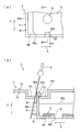
- a power supply device 1 according to the present embodiment is used as a power supply device for an electric vehicle, a hybrid vehicle, or the like, and as shown in FIG. 1, a battery assembly 2, a bus bar module 3 attached to the battery assembly 2, and a battery assembly. 2 and a pair of electric wires 4 connected to 2.
- the longitudinal direction is the longitudinal direction of the bus bar module 3 and is indicated by an arrow X in the drawing.
- the width direction is the width direction of the bus bar module 3 orthogonal to the longitudinal direction X, and is indicated by an arrow Y in the figure.
- the vertical direction is a direction orthogonal to the longitudinal direction X and the width direction Y, and is indicated by an arrow Z in the figure, and the vertical direction is based on FIG.
- the battery assembly 2 includes a plurality of batteries (not shown) and electrodes (not shown) provided on the batteries, and the batteries have electrodes of different polarities adjacent to each other in the longitudinal direction X. Are listed.
- the bus bar module 3 includes a bus bar 5 that connects adjacent electrodes of the battery assembly 2, a case 6 that houses the bus bar 5, and a cover 7 that covers the case 6. It is configured.
- the bus bar 5 is formed by drilling a metal plate material or the like, and two electrode insertion holes 51 through which an electrode (not shown) of the battery assembly 2 is inserted are provided side by side in the longitudinal direction X.
- the case 6 is formed using an insulating material such as synthetic resin, and includes a housing portion 61 that houses the bus bar 5, a plurality of wire holding portions 62 that hold the wires 4, and a locking portion 63 that locks the cover 7. And is configured.
- the accommodating portion 61 is formed to have a bottom wall 64, a peripheral wall 65 a extending in the longitudinal direction X, and a peripheral wall 65 b extending in the width direction Y while standing from the bottom wall 64.
- An electrode insertion hole 641 is formed in the bottom wall 64 in accordance with the position of the electrode insertion hole 51 of the bus bar 5 accommodated in the accommodating portion 61.
- a locking portion 63 for locking the cover 7 is formed on the peripheral wall 65a extending in the longitudinal direction X.
- the locking portion 63 includes an extending portion 631 extending upward (in the direction indicated by an arrow Z in the drawing) from the upper end of the peripheral wall 65a extending in the longitudinal direction X, and the bus bar 5 in the width direction Y from the extending portion 631.
- the latching claw 632 is bent in the accommodating direction (inward of the accommodating portion 61).
- the electric wire holding part 62 is provided in plural along the longitudinal direction X with a space between each other, and the pair of electric wires 4 are respectively attached to the electric wire holding part 62 so as to be attached along the longitudinal direction X. It is pulled out from one end of the bus bar module 3.
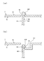
- the cover 7 is formed using an insulating material such as synthetic resin, and when covering the case 6, an inner surface portion 71 located on the housing portion 61 side, an exposed surface portion 72 located on the opposite side of the inner surface portion 71, And an engaging hole 73 that communicates from the exposed surface portion 72 to the inner surface portion 71.
- the exposed surface portion 72 is formed having a concave portion 721 formed in a concave shape on the inner surface portion 71 side, and the locking hole 73 is formed at the bottom of the concave portion 721.
- the locking portion 63 of the case 6 is inserted into the locking hole 73 from the inner surface 71 side of the cover 7 to the exposed surface portion 72 side, and is continuous with the exposed surface portion 72. Lock to the edge of the.
- the latching claw 632 and the edge of the latching hole 73 which is the latched portion overlap each other, and the gap on the bus bar 5 side in the housing portion 61 from the latching hole 73 is extended with the extended portion 631. It is blocked by the locking claw 632.
- the locking claw 632 is locked to the locked portion that is continuous with the exposed surface portion 72 of the cover 7, whereby the locked state between the case 6 and the cover 7 is confirmed from the exposed surface portion 72 side. It is possible to improve the visibility when confirming the locked state.
- the latching claw 632 is formed to be bent toward the bus bar 5 in the accommodating portion 61, the gap on the bus bar 5 side in the latching hole 73 is formed between the extended portion 631 of the latching portion 63 and the latching claw 632. Therefore, the range in which the wire jig G can enter from the locking hole 73 is the range indicated by the arrow P in FIG. 2B, and the wire jig in the direction in which the bus bar 5 is accommodated. Intrusion of the tool G and foreign matter can be prevented.
- the locking hole 73 is provided at the bottom of the concave portion 721 formed concavely from the exposed surface portion 72 side to the inner surface portion 71 side, when the locking claw 632 is locked to the locked portion, The protrusion of the locking claw 632 toward the exposed surface portion 72 can be reduced or prevented from protruding, and the locked state between the case 6 and the cover 7 can be easily released during assembly. Can be suppressed.
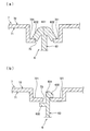
- the locking hole 73 is formed at the bottom of the recess 721 provided in the exposed surface portion 72, but as shown in FIG. 3A, the locking hole 73 is flat without being provided with the recess 721.
- a locking hole 73 may be formed in the exposed surface portion 72.
- the recess 721 may not be formed on the side where the locking claw 632 is not provided, that is, the locking hole 73 is formed at the end of the recess 721. It may be.
- the locking portion 63 is formed in the upward direction Z from the upper end of the peripheral wall 65a extending in the longitudinal direction X of the accommodating portion 61
- the engaging portion 63 extends in the width direction Y of the accommodating portion 61 and connects the adjacent accommodating portions 61 to each other.
- the locking claws 632 may be formed in one direction as in the above embodiment.
- the locking claws 632 face both the adjacent bus bars 5. By being bent and formed, it is possible to prevent the wire jig G and foreign matter from entering and touching the adjacent bus bars 5.
- one of the locking claws 632 bent in both directions is located at a position overlapping the exposed surface portion 72 side of the cover 7 when the locking claw 632 is locked. Instead, it may be formed at a position overlapping the inner surface 71 side.
- the locking part 63 does not have to extend from the upper ends of the peripheral walls 65a and 65b of the housing part 61. If the locking hole 73 can be locked on the exposed surface part 72 side of the cover 7, any of the cases 6 can be provided. It can be provided in the position.
Abstract
ケースとカバーとの係止状態を目視確認する際の視認性が良好であり、収容部内に針金治具や異物が侵入し難いバスバーモジュールを提供する。 バスバーモジュール(3)は、バスバー(5)と、バスバー(5)を収容する収容部(61)を有するケース(6)と、ケース(6)を覆うカバー(7)と、を備えて構成され、収容部(61)は、底壁(64)と、底壁(64)から立設して長手方向Xに延びる周壁(65a)と、幅方向に延びる周壁(65b)と、を有して構成され、周壁(65a)は、周壁(65a)から上方向に延びる延設部(631)と、延設部(631)の先端に設けられるとともに、バスバー(5)が収容される方向に折れ曲がった係止爪(632)と、を有して構成され、係止爪(632)は、カバー(7)に設けられた係止孔(73)とカバー(7)の露出面部(72)側において係止する。
Description
本発明は、複数の電池を備える電池集合体の電極同士を互いに接続するバスバーモジュール及び電池集合体とバスバーモジュールとを備える電源装置に関する。
電気自動車やハイブリッド自動車などの電源装置は、異なる極性の電極が隣り合うように並べられた複数の電池を有する電池集合体と、各々の電池の電極同士を接続するバスバーモジュールと、を備えて構成され、従来、バスバーモジュールについて種々提案されている(例えば、特許文献1参照)。特許文献1に記載のバスバーモジュールは、バスバーを収容する収容部と、収容部を覆うカバーと、を備えて構成され、収容部は、周壁上に係止爪を有し、カバーは、開口部と、開口部から収容部側に延びた立壁部と、立壁部に形成された係止孔と、を有して形成されている。このカバーの収容部側において係止爪と係止孔とが係止することにより、カバーが収容部に係止されるようになっている。
しかしながら、従来のバスバーモジュールでは、カバーの収容部側において係止爪と係止孔とが係止するため、収容部とカバーとの係止状態を目視確認する際に、カバーに設けられた開口部から収容部側を覗いて確認する必要がある。さらに、バスバーモジュールの開口部から収容部に針金治具や異物が侵入してバスバー等に触れることを抑制するために開口部を小さく形成した場合に、カバーと収容部との係止状態を確認する際の視認性が悪くなるという問題があった。また、開口部から収容部内に針金治具や異物が侵入しやすいという問題があった。
従って、本発明は、上記のような問題点に着目し、ケースとカバーとの係止状態を目視確認する際の視認性が良好であり、収容部内に針金治具や異物が侵入し難いバスバーモジュールを提供することを目的とする。
上記課題を解決するために、本発明のバスバーモジュールは、複数の電池を備えるとともに、異なる極性の電極が隣り合うように該電池が並べられた電池集合体の前記電極同士を接続するバスバーモジュールであって、前記電極同士を接続する複数のバスバーと、該バスバーを収容するケースと、該ケースを覆うカバーと、を備えて構成され、前記ケースは、前記バスバーを収容する収容部と、前記カバーを係止する係止部と、を有して構成され、前記収容部は、底壁と、該底壁から立設する周壁と、を有し、前記係止部は、前記底壁から離れる方向に延びる延設部と、該延設部の先端から少なくとも前記収容部に収容された前記バスバー側に折れ曲がった係止爪と、を有して形成され、前記カバーは、前記ケースと対向する面と反対側に位置する露出面部と、該露出面部から前記収容部側に連通した係止孔と、を有して構成され、前記係止爪は、前記カバーの前記露出面部側に突出して、前記係止孔の縁に係止することを特徴とする。
本発明のバスバーモジュールによれば、ケースに設けられた係止爪がカバーの露出面部側に突出して、係止孔の縁に係止することにより、ケースとカバーとの係止状態をカバーの露出面部側において確認することができ、係止状態を確認する際の視認性を良好にすることができる。また、係止爪が収容部内のバスバー側に折れ曲がって形成されていることから、係止爪が係止孔の縁(被係止部)と重なって係止して、係止孔におけるバスバー側の隙間が係止爪と延設部とによって塞がれることにより、係止孔から収容部内への針金治具や異物の侵入を防止することができる。
また、請求項1に記載のバスバーモジュールにおいて、前記露出面部は、前記底壁に向かって凹に形成された凹部を有して形成され、前記係止孔は、前記凹部の底に形成されていることが好ましい。
このような構成によれば、収容部の係止爪が係止する係止孔が露出面部から収容部の底壁に向かって凹に形成された凹部の底に設けられていることにより、係止爪が係止孔に係止した際に、カバーの露出面部側への係止爪の突出が少なくなる、又は、係止爪を突出させないようにでき、組付け時などにケースとカバーとの係止状態が容易に解除されることを抑制することができる。
また、請求項1又は2に記載のバスバーモジュールにおいて、前記係止爪は、前記延設部の先端から、前記収容部に収容された前記バスバー側と、前記バスバー側の反対側と、に折れ曲がって形成されていることが好ましい。
このような構成によれば、係止爪が収容部に収容されたバスバー側と、バスバー側の反対側との両方向に折れ曲がって形成されていることから、係止孔における両方向への隙間が係止爪と延設部により塞がれることにより、係止孔から収容部内への針金治具や異物の侵入をより確実に防止することができる。
本発明の電源装置は、複数の電池を備えるとともに、異なる極性の電極が隣り合うように該電池が並べられた電池集合体と、請求項1~3のいずれか1項に記載されたバスバーモジュールと、を備えて構成されることを特徴とする。
本発明の電源装置によれば、ケースに設けられた係止爪がカバーの露出面部側に突出して、係止孔の縁に係止することにより、ケースとカバーとの係止状態をカバーの露出面部側において確認することができ、係止状態を確認する際の視認性を良好にすることができる。また、係止爪が収容部内のバスバー側に折れ曲がって形成されていることから、係止爪が露出面部の被係止部と重なって係止して、バスバー側の隙間が係止爪と延設部とに塞がれることにより、係止孔から収容部内への針金治具や異物の侵入を防止することができる。
以上のような本発明のバスバーモジュール及び電源装置によれば、係止爪がカバーの露出面部側において係止孔の縁に係止することから、ケースとカバーとの係止状態をカバーの露出面部側において確認することができ、ケースとカバーとの係止状態を目視確認する際の視認性を良好にすることができる。また、係止爪が収容部内のバスバー側に折れ曲がって形成されていることから、係止孔からバスバー側への隙間が係止爪と延設部とにより塞がれて、係止孔から収容部内への針金治具や異物の侵入を防止することができる。
本発明の一実施形態に係るバスバーモジュール及び電源装置について、図1,2を参照して説明する。本実施形態の電源装置1は、電気自動車やハイブリッド自動車などの電源装置として用いられ、図1に示すように、電池集合体2と、電池集合体2に取り付けられるバスバーモジュール3と、電池集合体2に接続される一対の電線4と、を備えて構成されている。なお、本明細書において、長手方向とは、バスバーモジュール3の長手方向であり、図中の矢印Xで示す。また、幅方向とは、長手方向Xに直交するバスバーモジュール3の幅方向であり、図中の矢印Yで示す。上下方向とは、長手方向X及び幅方向Yに直交する方向であり、図中の矢印Zで示し、上下は図1を基準とする。
電池集合体2は、不図示の複数のバッテリと、バッテリにそれぞれ設けられた不図示の電極と、を有して構成されるとともに、バッテリは、異なる極性の電極が長手方向Xに隣り合うように並べられている。
バスバーモジュール3は、図1,2に示すように、電池集合体2の隣り合う電極同士を接続するバスバー5と、バスバー5を収容するケース6と、ケース6を覆うカバー7と、を備えて構成されている。
バスバー5は、金属板材に穴開け加工等を施して形成され、電池集合体2の不図示の電極が挿通される電極挿通孔51が長手方向Xに2つ並んで設けられている。
ケース6は、合成樹脂等の絶縁性素材を用いて形成され、バスバー5を収容する収容部61と、電線4を保持する複数の電線保持部62と、カバー7を係止する係止部63と、を有して構成されている。
収容部61は、底壁64と、底壁64から立設するとともに、長手方向Xに延びる周壁65aと、幅方向Yに延びる周壁65bと、を有して形成されている。底壁64には、収容部61に収容されるバスバー5の電極挿通孔51の位置に合わせて、電極挿通孔641が形成されている。
また、長手方向Xに延びる周壁65aには、カバー7を係止する係止部63が形成されている。係止部63は、長手方向Xに延びる周壁65aの上端から上方向(図中の矢印Zで示す方向)に延びる延設部631と、延設部631から、幅方向Yのうちバスバー5が収容される方向(収容部61の内方)に折れ曲がった係止爪632と、を有して構成されている。
電線保持部62は、互いに間隔をあけて長手方向Xに沿って複数設けられており、一対の電線4は、電線保持部62にそれぞれ保持されることにより、長手方向Xに沿って取り付けられ、バスバーモジュール3の一方側の端部から引き出されている。
カバー7は、合成樹脂等の絶縁性素材を用いて形成され、ケース6を覆う際に収容部61側に位置する内面部71と、内面部71とは反対側に位置する露出面部72と、露出面部72から内面部71に連通した係止孔73と、を有して構成されている。露出面部72は、内面部71側に凹に形成された凹部721を有して形成され、係止孔73は、凹部721の底に形成されている。
次に、ケース6とカバー7との係止方法について、図2を参照して説明する。図2(b)に示すように、ケース6の係止部63は、カバー7の内面部71側から露出面部72側へ係止孔73に挿通され、露出面部72に連続する係止孔73の縁に係止する。このとき、係止爪632と被係止部である係止孔73の縁とは重なっており、また、係止孔73から収容部61内のバスバー5側の隙間は、延設部631と係止爪632とにより塞がれている。
本実施形態によれば、係止爪632がカバー7の露出面部72に連続する被係止部に係止することにより、ケース6とカバー7との係止状態を露出面部72側から確認することができ、係止状態を確認する際の視認性を良好にすることができる。
また、係止爪632が収容部61内のバスバー5側に折れ曲がって形成されていることにより、係止孔73におけるバスバー5側の隙間が係止部63の延設部631と係止爪632とにより塞がれることから、係止孔73から針金治具Gが侵入することができる範囲は図2(b)の矢印Pで示す範囲となり、バスバー5が収容されている方向への針金治具Gや異物の侵入を防止することができる。
また、係止孔73が露出面部72側から内面部71側に凹に形成された凹部721の底に設けられていることから、係止爪632が被係止部に係止した際に、係止爪632の露出面部72側への突出が少なくなる、又は、突出させないようにすることができ、組付け時などにケース6とカバー7との係止状態が容易に解除されることを抑制することができる。
なお、本発明は、前記実施形態に限定されるものではなく、本発明の目的が達成できる他の構成等を含み、以下に示すような変形等も本発明に含まれる。
例えば、前記実施形態においては、係止孔73は露出面部72に設けられた凹部721の底に形成されていたが、図3(a)に示すように、凹部721が設けられずにフラットな露出面部72に係止孔73が形成されていてもよい。また、図3(b)に示すように、係止爪632が設けられていない側には、凹部721が形成されていなくてもよく、即ち、凹部721の端に係止孔73が形成されていてもよい。
また、係止部63は、収容部61の長手方向Xに延びた周壁65aの上端から上方向Zに形成されていたが、収容部61の幅方向Yに延びて、隣り合う収容部61を仕切る周壁65bの上端から上方向Zに形成されていてもよい。この場合、前記実施形態のように係止爪632が一方向に形成されていてもよいが、例えば、図4(a)に示すように、係止爪632が隣り合うバスバー5の両方に向かって折れ曲がって形成されることにより、針金治具Gや異物が侵入して隣り合うバスバー5に触れることを防止することができる。
また、図4(b)に示すように、両方向に折れ曲がって形成される係止爪632のうち一方は、係止爪632が係止した状態において、カバー7の露出面部72側に重なる位置ではなく、内面部71側に重なる位置に形成されていてもよい。
また、係止部63は、収容部61の周壁65a,65bの上端から延びていなくてもよく、カバー7の露出面部72側において係止孔73を係止することができれば、ケース6の任意の位置に設けることができる。
その他、本発明を実施するための最良の構成、方法などは、以上の記載で開示されているが、本発明は、これに限定されるものではない。すなわち、本発明は、主に特定の実施形態に関して特に図示され、且つ、説明されているが、本発明の技術的思想および目的の範囲から逸脱することなく、以上述べた実施形態に対し、形状、材質、数量、その他の詳細な構成において、当業者が様々な変形を加えることができるものである。
従って、上記に開示した形状、材質などを限定した記載は、本発明の理解を容易にするために例示的に記載したものであり、本発明を限定するものではないから、それらの形状、材質などの限定の一部、もしくは全部の限定を外した部材の名称での記載は、本発明に含まれるものである。
1 電源装置
2 電池集合体
3 バスバーモジュール
5 バスバー
6 ケース
7 カバー
61 収容部
63 係止部
64 底壁
65a,65b 周壁
72 露出面部
73 係止孔
631 延設部
632 係止爪
721 凹部
2 電池集合体
3 バスバーモジュール
5 バスバー
6 ケース
7 カバー
61 収容部
63 係止部
64 底壁
65a,65b 周壁
72 露出面部
73 係止孔
631 延設部
632 係止爪
721 凹部
Claims (4)
- 複数の電池を備えるとともに、異なる極性の電極が隣り合うように該電池が並べられた電池集合体の前記電極同士を接続するバスバーモジュールであって、
前記電極同士を接続する複数のバスバーと、該バスバーを収容するケースと、該ケースを覆うカバーと、を備えて構成され、
前記ケースは、前記バスバーを収容する収容部と、前記カバーを係止する係止部と、を有して構成され、
前記収容部は、底壁と、該底壁から立設する周壁と、を有し、前記係止部は、前記底壁から離れる方向に延びる延設部と、該延設部の先端から少なくとも前記収容部に収容された前記バスバー側に折れ曲がった係止爪と、を有して形成され、
前記カバーは、前記ケースと対向する面と反対側に位置する露出面部と、該露出面部から前記収容部側に連通した係止孔と、を有して構成され、
前記係止爪は、前記カバーの前記露出面部側に突出して、前記係止孔の縁に係止することを特徴とするバスバーモジュール。 - 前記露出面部は、前記底壁に向かって凹に形成された凹部を有して形成され、
前記係止孔は、前記凹部の底に形成されていることを特徴とする請求項1に記載のバスバーモジュール。 - 前記係止爪は、前記延設部の先端から、前記収容部に収容された前記バスバー側と、前記バスバー側の反対側と、の両側に折れ曲がって形成されていることを特徴とする請求項1又は2に記載のバスバーモジュール。
- 複数の電池を備えるとともに、異なる極性の電極が隣り合うように該電池が並べられた電池集合体と、請求項1~3のいずれか1項に記載されたバスバーモジュールと、を備えて構成されることを特徴とする電源装置。
Applications Claiming Priority (2)
| Application Number | Priority Date | Filing Date | Title |
|---|---|---|---|
| JP2013121225A JP6192370B2 (ja) | 2013-06-07 | 2013-06-07 | バスバモジュール及び電源装置 |
| JP2013-121225 | 2013-06-07 |
Publications (1)
| Publication Number | Publication Date |
|---|---|
| WO2014196629A1 true WO2014196629A1 (ja) | 2014-12-11 |
Family
ID=52008258
Family Applications (1)
| Application Number | Title | Priority Date | Filing Date |
|---|---|---|---|
| PCT/JP2014/065093 WO2014196629A1 (ja) | 2013-06-07 | 2014-06-06 | バスバーモジュール及び電源装置 |
Country Status (2)
| Country | Link |
|---|---|
| JP (1) | JP6192370B2 (ja) |
| WO (1) | WO2014196629A1 (ja) |
Cited By (1)
| Publication number | Priority date | Publication date | Assignee | Title |
|---|---|---|---|---|
| JP2021068561A (ja) * | 2019-10-23 | 2021-04-30 | 株式会社Gsユアサ | 蓄電装置 |
Families Citing this family (2)
| Publication number | Priority date | Publication date | Assignee | Title |
|---|---|---|---|---|
| JP6477366B2 (ja) * | 2015-09-01 | 2019-03-06 | トヨタ自動車株式会社 | 電池パック |
| WO2023178518A1 (zh) * | 2022-03-22 | 2023-09-28 | 东莞新能安科技有限公司 | 电池系统及用电设备 |
Citations (14)
| Publication number | Priority date | Publication date | Assignee | Title |
|---|---|---|---|---|
| JPH0439814A (ja) * | 1990-06-05 | 1992-02-10 | Tokai Carbon Co Ltd | 導電性シートの製造方法 |
| JPH1186832A (ja) * | 1997-09-04 | 1999-03-30 | Harness Sogo Gijutsu Kenkyusho:Kk | バッテリーの接続構造 |
| JP2002184371A (ja) * | 2000-12-12 | 2002-06-28 | Honda Motor Co Ltd | バスバーの位置決め治具 |
| JP2006147546A (ja) * | 2004-10-22 | 2006-06-08 | Nissan Motor Co Ltd | 電池モジュールおよび組電池 |
| JP2006324349A (ja) * | 2005-05-17 | 2006-11-30 | Honda Motor Co Ltd | 蓄電装置 |
| JP2009289429A (ja) * | 2008-05-27 | 2009-12-10 | Keihin Corp | 組電池の電源制御装置 |
| JP2011018478A (ja) * | 2009-07-07 | 2011-01-27 | Autonetworks Technologies Ltd | 電池接続アセンブリ |
| JP2011060675A (ja) * | 2009-09-14 | 2011-03-24 | Yazaki Corp | 電源装置のカバー構造 |
| JP2012059663A (ja) * | 2010-09-13 | 2012-03-22 | Auto Network Gijutsu Kenkyusho:Kk | 組電池配線モジュール |
| JP2012164598A (ja) * | 2011-02-09 | 2012-08-30 | Yazaki Corp | バスバモジュール及び電源装置 |
| JP2012243608A (ja) * | 2011-05-20 | 2012-12-10 | Yazaki Corp | バスバモジュールおよび該バスバモジュールを備えた電源装置 |
| JP2013020798A (ja) * | 2011-07-11 | 2013-01-31 | Auto Network Gijutsu Kenkyusho:Kk | 電池配線モジュールのカバー、電池配線モジュール及び電池モジュール |
| JP2013037986A (ja) * | 2011-08-10 | 2013-02-21 | Auto Network Gijutsu Kenkyusho:Kk | カバー付き電池配線モジュール |
| JP2013157128A (ja) * | 2012-01-27 | 2013-08-15 | Yazaki Corp | 電源装置 |
Family Cites Families (1)
| Publication number | Priority date | Publication date | Assignee | Title |
|---|---|---|---|---|
| JPH04133348U (ja) * | 1991-05-30 | 1992-12-11 | 株式会社東芝 | 電子機器用電池収納装置 |
-
2013
- 2013-06-07 JP JP2013121225A patent/JP6192370B2/ja active Active
-
2014
- 2014-06-06 WO PCT/JP2014/065093 patent/WO2014196629A1/ja active Application Filing
Patent Citations (14)
| Publication number | Priority date | Publication date | Assignee | Title |
|---|---|---|---|---|
| JPH0439814A (ja) * | 1990-06-05 | 1992-02-10 | Tokai Carbon Co Ltd | 導電性シートの製造方法 |
| JPH1186832A (ja) * | 1997-09-04 | 1999-03-30 | Harness Sogo Gijutsu Kenkyusho:Kk | バッテリーの接続構造 |
| JP2002184371A (ja) * | 2000-12-12 | 2002-06-28 | Honda Motor Co Ltd | バスバーの位置決め治具 |
| JP2006147546A (ja) * | 2004-10-22 | 2006-06-08 | Nissan Motor Co Ltd | 電池モジュールおよび組電池 |
| JP2006324349A (ja) * | 2005-05-17 | 2006-11-30 | Honda Motor Co Ltd | 蓄電装置 |
| JP2009289429A (ja) * | 2008-05-27 | 2009-12-10 | Keihin Corp | 組電池の電源制御装置 |
| JP2011018478A (ja) * | 2009-07-07 | 2011-01-27 | Autonetworks Technologies Ltd | 電池接続アセンブリ |
| JP2011060675A (ja) * | 2009-09-14 | 2011-03-24 | Yazaki Corp | 電源装置のカバー構造 |
| JP2012059663A (ja) * | 2010-09-13 | 2012-03-22 | Auto Network Gijutsu Kenkyusho:Kk | 組電池配線モジュール |
| JP2012164598A (ja) * | 2011-02-09 | 2012-08-30 | Yazaki Corp | バスバモジュール及び電源装置 |
| JP2012243608A (ja) * | 2011-05-20 | 2012-12-10 | Yazaki Corp | バスバモジュールおよび該バスバモジュールを備えた電源装置 |
| JP2013020798A (ja) * | 2011-07-11 | 2013-01-31 | Auto Network Gijutsu Kenkyusho:Kk | 電池配線モジュールのカバー、電池配線モジュール及び電池モジュール |
| JP2013037986A (ja) * | 2011-08-10 | 2013-02-21 | Auto Network Gijutsu Kenkyusho:Kk | カバー付き電池配線モジュール |
| JP2013157128A (ja) * | 2012-01-27 | 2013-08-15 | Yazaki Corp | 電源装置 |
Cited By (1)
| Publication number | Priority date | Publication date | Assignee | Title |
|---|---|---|---|---|
| JP2021068561A (ja) * | 2019-10-23 | 2021-04-30 | 株式会社Gsユアサ | 蓄電装置 |
Also Published As
| Publication number | Publication date |
|---|---|
| JP2014238987A (ja) | 2014-12-18 |
| JP6192370B2 (ja) | 2017-09-06 |
Similar Documents
| Publication | Publication Date | Title |
|---|---|---|
| JP6095948B2 (ja) | バスバモジュール及び電源装置 | |
| JP6163369B2 (ja) | バスバモジュール及び電源装置 | |
| JP6130733B2 (ja) | バスバーモジュール | |
| JP2013016381A (ja) | 電池配線モジュール | |
| JP6186922B2 (ja) | 配線モジュール | |
| JP6512147B2 (ja) | 外部接続バスバー保持構造 | |
| JP2014060044A (ja) | 電池用配線モジュール | |
| JP5667287B2 (ja) | 電気接続箱 | |
| JP6062213B2 (ja) | バスバモジュール及び電源装置 | |
| EP3098878B1 (en) | Wiring module | |
| WO2015015667A1 (ja) | 配線モジュール | |
| WO2014196629A1 (ja) | バスバーモジュール及び電源装置 | |
| JP6836889B2 (ja) | 電気接続箱、及び、ワイヤハーネス | |
| JP6125311B2 (ja) | バスバモジュール及び電源装置 | |
| JP2010074955A (ja) | 電気接続箱 | |
| CN109148803B (zh) | 导体模块装接结构 | |
| JP6162470B2 (ja) | バスバモジュール | |
| JP6215580B2 (ja) | 電気接続箱 | |
| JP2014017167A (ja) | ヒューズホルダとヒューズカバーとの固定構造 | |
| JP6140519B2 (ja) | バスバモジュール及び電源装置 | |
| JP2008108660A (ja) | ワイヤハーネス用コネクタ | |
| JP5994142B2 (ja) | 電気接続箱 | |
| JP5758170B2 (ja) | 電気接続箱 | |
| JP6710109B2 (ja) | 回路遮断器 | |
| JP5758171B2 (ja) | 電気接続箱 |
Legal Events
| Date | Code | Title | Description |
|---|---|---|---|
| 121 | Ep: the epo has been informed by wipo that ep was designated in this application |
Ref document number: 14807849 Country of ref document: EP Kind code of ref document: A1 |
|
| NENP | Non-entry into the national phase |
Ref country code: DE |
|
| 122 | Ep: pct application non-entry in european phase |
Ref document number: 14807849 Country of ref document: EP Kind code of ref document: A1 |